EP2469471A1 - Tomographic reconstruction of an object in motion - Google Patents
Tomographic reconstruction of an object in motion Download PDFInfo
- Publication number
- EP2469471A1 EP2469471A1 EP11193790A EP11193790A EP2469471A1 EP 2469471 A1 EP2469471 A1 EP 2469471A1 EP 11193790 A EP11193790 A EP 11193790A EP 11193790 A EP11193790 A EP 11193790A EP 2469471 A1 EP2469471 A1 EP 2469471A1
- Authority
- EP
- European Patent Office
- Prior art keywords
- images
- sequence
- xyz
- image
- projection images
- Prior art date
- Legal status (The legal status is an assumption and is not a legal conclusion. Google has not performed a legal analysis and makes no representation as to the accuracy of the status listed.)
- Granted
Links
Images



Classifications
-
- G—PHYSICS
- G06—COMPUTING OR CALCULATING; COUNTING
- G06T—IMAGE DATA PROCESSING OR GENERATION, IN GENERAL
- G06T12/00—Tomographic reconstruction from projections
- G06T12/20—Inverse problem, i.e. transformations from projection space into object space
-
- G—PHYSICS
- G06—COMPUTING OR CALCULATING; COUNTING
- G06T—IMAGE DATA PROCESSING OR GENERATION, IN GENERAL
- G06T2211/00—Image generation
- G06T2211/40—Computed tomography
- G06T2211/404—Angiography
-
- G—PHYSICS
- G06—COMPUTING OR CALCULATING; COUNTING
- G06T—IMAGE DATA PROCESSING OR GENERATION, IN GENERAL
- G06T2211/00—Image generation
- G06T2211/40—Computed tomography
- G06T2211/424—Iterative
Definitions
- the invention relates to the field of tomographic reconstruction and more particularly to the reconstruction of a sequence of 3D image(s) describing an object to be imaged by means of a contrast product.
- Tomography allows making images of slices of a region of interest of an object by acquiring projections.
- Figure 1 schematically illustrates the acquisition of 2D images of an organ and the tomographic reconstruction of a 3D image of this organ.
- Reconstruction of a 3D image by tomography consists of emitting X-rays 10 coming from a source to the organ 12, the X-rays being emitted according to different angulations l ⁇ ⁇ 1,..., L ⁇ which define the trajectory Tr of the source (commonly rotation, also known as spin).
- the X-rays 10 are detected by a detector 13 to form a set of 2D projections.
- a detector 13 There are as many 2D projections acquired as relevant angulations (or L projections for the trajectory). Acquisition is carried out by a detector (not shown) located opposite the source of X-rays 11, for example a digital camera.
- One application of the tomography is the detection and characterisation of a lesion in an organ, for example stenosis in a vessel of a patient.
- the acquired 2D projections are used to reconstruct a 3D image of the object.
- This 3D image is more precisely a 3D map of the coefficients of attenuation to X-rays of the traversed medium.
- An iterative 3D reconstruction process is known. This process is based on a discrete and matricial expression of the problem of tomographic reconstruction.
- Such a process is carried out in a processing unit of a medical imaging system.
- R ⁇ f p
- p is the set of L projections acquired
- R is a projection operator which models the tomographic imaging system and its trajectory of acquisition of L projections p
- f is the 3D image of the object to be reconstructed.
- the problem of tomographic reconstruction is determining f by knowing p and R .
- the image of the vessels alone is obtained by subtracted angiography where two acquisitions are made: one without contrast product, known as “mask” and noted p M , and a second one, known as “opacified” and noted p o , identical in terms of geometry, but after injection of the contrast product. The order in which these acquisitions are done does not matter.
- the image of the vessels in the images is obtained by opacified subtraction minus mask.
- Subtracted tomographic acquisition occurs therefore as the succession of two tomographic acquisitions, masked and opacified, such that an image of the acquisition mask (same geometry) allowing subtraction corresponds to each image of the opacified acquisition.
- the contrast product dilutes rapidly in the blood flow.
- the maximal rotation speed of the tomographic system is generally used to limit the volume of contrast product necessary for opacified acquisition.
- the angular sampling conditions of the tomography also involve obtaining a few hundreds of images by acquisition (commonly 600). Angiography systems are however limited in speed of rotation (commonly 40°/s) and in image rate (commonly 50 Hz) such that the total number of images acquired (for example 250) is sufficient for the display of strong contrasts (bones and opacified vessels) but insufficient for weak contrasts (soft tissue and perfused tissue). It is said that contrast resolution is limited by sampling.
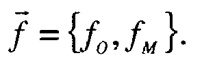
- the present invention consists of simultaneously using the two mask and opacified acquisitions to reconstruct the associated opacified and subtracted 3D mask images in order to reduce the number of projections necessary for detection of weak contrasts in the reconstructed 3D images. For this, it is based on temporal interpretation of acquisition with injection of contrast product in considering two temporal points: t o for the injection and t M for the mask. It hypothesises that the time changes caused by injection of contrast product are compressible.
- This hypothesis proposes a method of reconstruction for compensating sub-sampling of variations linked to injection, and therefore more particularly improving reconstruction of the subtracted 3D image.
- R ( t M ) samples a circular trajectory with an angular pitch ⁇
- R ( t o ) samples a circular trajectory with the angular same pitch ⁇
- the invention is based on the following hypotheses:
- a first aspect of the invention is a method for processing a sequence of a plurality of 2D projection images of an object of interest, acquired by means of a medical imaging system comprising a source of X-rays, the source being adapted to shift around the object, the method comprising the following steps:
- a second aspect of the invention is a medical imaging system comprising: an acquisition system comprising a source of radiation, a sensor, for the acquisition of a plurality of 2D projection images of an object; storage means of the 2D projection images acquired; a system for the treatment of the 2D projection images acquired designed to utilise a method according to the first aspect of the invention.
- a third aspect of the invention is a computer program product comprising programming code instructions for executing steps of the method according to the first aspect of the invention.
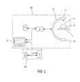
- Figure 2 schematically illustrates a medical imaging system 100 for the acquisition of 2D projection images for the reconstruction of a 3D image of an organ. Such a system is used especially for the detection and characterisation of stenoses in vessels.
- the medical imaging system 100 comprises a support 1 for receiving a patient 12 to be examined, a source 11 designed to emit a beam 10 of X-rays, a detector 13 arranged opposite the source 11 and configured to detect the X-rays emitted by the source 11, a control unit 6, a storage unit 7 and a display unit 8.
- the source 11 of X-rays and the detector 13 are connected for example by means of an arch 15.
- the detector 13 can be a semi-conductor image sensor comprising for example caesium phosphorous iodide (scintillater) on a matrix of transistor/photodiode of amorphous silicon.
- Other adequate detectors are: a CCD sensor, a direct digital detector which directly converts X-rays into digital signals.
- the detector 13 illustrated in Figure 2 is planar and defines a flat image surface, while other geometries can naturally be suitable.
- the control unit 6 controls the acquisition by fixing several parameters such as the dose of radiation to be emitted by the X-ray source and the positioning of the source 11 and of the detector 13. It is connected to the arch 15 by wire or wireless connection.
- the control unit 6 can comprise a reading device (not shown), for example a disc reader, a CD-ROM, DVD-ROM reader, or connection ports for reading the instructions of the process for treating an instruction medium (not shown), such as a diskette, a CD-ROM, DVD-ROM, or USB flash drive or more generally by any removable memory medium or even via a network connection.
- a reading device for example a disc reader, a CD-ROM, DVD-ROM reader, or connection ports for reading the instructions of the process for treating an instruction medium (not shown), such as a diskette, a CD-ROM, DVD-ROM, or USB flash drive or more generally by any removable memory medium or even via a network connection.
- the storage unit 7 is connected to the control unit 6 for recording parameters and acquired images. It is possible to ensure that the storage unit 7 is located inside the control unit 6 or outside it.
- the storage unit 7 can be formed by a hard drive or SSD, or any other removable and rewritable storage means (USB flash drives, memory cards etc.).
- the storage unit 7 can be ROM/RAM memory of the control unit 6, a USB flash drive, a memory card, central server memory.
- the display unit 8 is connected to the control unit 6 for displaying the acquired images and/or information on the acquisition control parameters.
- the display unit 8 can be for example a computer screen, a monitor, a flat screen, plasma screen or any type of display device of known type.
- Such a display unit 8 allows a practitioner to control reconstruction and/or display of the 2D images acquired.
- the medical imaging system 100 is coupled to a processing system 200.
- the processing system 200 comprises a calculation unit 9 and storage unit 10.
- the processing system 200 receives the images acquired and stored in the unit memory 4 of the medical imaging system 100 from which it makes a certain number of treatments (see hereinafter), for example reconstruction of a 3D image from 2D images.
- Transmission of data from the storage unit 4 of the medical imaging system 100 to the calculation unit 9 of the processing system 200 can be done over an internal or external information network or by means of any adequate physical memory medium such as diskettes, CD-ROM, DVD-ROM, external hard drive, USB flash drive, SD card, etc.
- the calculation unit 9 is for example a computer or computers, a processor or processors, a microcontroller or microcontrollers, a microcomputer or microcomputers, a programmable automaton or automatons, a specific application integrated circuit or circuits, other programmable circuits, or other devices including a computer such as a workstation.
- the calculator 9 can comprise a reading device (not shown), for example a disc reader, a CD-ROM, DVD-ROM reader, or connection ports for reading the instructions of the process for treating an instruction medium (not shown), such as a diskette, a CD-ROM, DVD-ROM, or USB flash drive or more generally by any removable memory medium or even via a network connection.
- a reading device for example a disc reader, a CD-ROM, DVD-ROM reader, or connection ports for reading the instructions of the process for treating an instruction medium (not shown), such as a diskette, a CD-ROM, DVD-ROM, or USB flash drive or more generally by any removable memory medium or even via a network connection.
- the processing system comprises a storage unit 14 for storing data generated by the calculation unit 9.
- the calculation unit 9 can be connected to the display unit 8 (as in Figure 2 ) or else to another display unit (not shown).
- the image processing method is for example implemented in the treatment unit 200 of the medical imaging system illustrated in Figure 2 .
- the greyed object corresponds to the object in which a contrast product was injected by means of an injection device 14 of contrast product.
- the sets of 2D projection images p ⁇ are for example previously acquired and recovered from the storage unit 14 of the processing unit 200 of the medical imaging system 100 and treatment of 2D projection images is carried out in the calculator 9 of the processing unit 200 of the medical imaging system.
- R diag ⁇ R(t n ) ⁇ for t n ⁇ ⁇ t o , t M ⁇ is the projection operator, diagonal by block, which models sampling conducted by the medical imaging system during acquisition with and without contrast product. It verifies
- R ( t o ) R ( t M ) is privileged, for lack of adequate reconstruction.
- the reconstructed 3D images are affected by sub-sampling striae.
- the aim of the invention is to propose a reconstruction method where sub-sampling can be compensated by a priori mathematics which makes it an advantage to have R ( t o ) ⁇ R ( t M ) and thus increases the contrast resolution of all reconstructions.
- the image g *( t M ) is also degraded if the number of 2D projections of p ( t M ) is the same as for p ( t o ), as is the case in common practice which minimises the total dose of examination.
- S g ⁇ ⁇ ⁇ xyz ⁇ H t ⁇ g ⁇ ⁇ 1
- the type of spatial compression transform (transform in wavelets, gradient, identity,%) is defined independently for each constituent according to the hypotheses of compressibility which can be done on each of the constituents. In particular, if one of the constituents is not compressible, the transform which is associated with it is zero ( ⁇ ⁇ or ⁇ ⁇ is zero).
- the corollary of the compressibility hypothesis linked to injection is a redundancy hypothesis of the information not affected by injection.
- the aim of decomposition H t is to combine the mask and opacified 3D images so that the redundant parts, in other words the parts not affected by the contrast product and therefore common to the two images, are determined from the information available at the same time in p ( t M ) and p ( t o ).
- the estimation g ⁇ * ⁇ is such that the set of restrictions is verified: variations due to injection are determined by the data obtained at the time t o only, the redundant parts are determined from times t o and t M , and the missing parts from the compressibility hypothesis.
- An iterative convex optimisation algorithm for minimising J g ⁇ ⁇ ⁇ is known, for example one of those described or referenced in [ Afonso MV, Bioucas-Dias JM, Figueiredo MA., "Fast image recovery using variable splitting and constrained optimization. " IEEE Trans Image Process. (9): 2345-56 ] and [ Beck A, Teboulle M. "Fast gradient-based algorithms for constrained total variation image denoising and deblurring problems. " IEEE Trans. Image Process. 18(11):2419-34 ].
- g ⁇ ⁇ ⁇ A ⁇ ⁇ ⁇ ⁇ g ⁇ ⁇ ⁇ ⁇ - 1 ⁇ ⁇ ⁇ ⁇ 2,..., ⁇ is determined iteratively E 3 , E 3 ', E 3 " which corresponds to the sequence g ⁇ ⁇ ⁇ minimising the functional J g ⁇ ⁇ ⁇ ⁇ relative to g for ⁇ ⁇ fixed starting out from g ⁇ ⁇ ⁇ ⁇ - 1 , resulting in E 4 , g ⁇ * ⁇ ⁇ g ⁇ 0 the approximate solution to the problem of tomographic reconstruction.
- the numbers of the steps do not correspond to the diagram which is itself erroneous: the arrow must return to step E3.
- the number of approximations ⁇ and the number of iterations by approximation ⁇ are fixed such that they form the best compromise between the quality of g ⁇ * ⁇ ⁇ g ⁇ 0 and the calculation time necessary for generation of g ⁇ * ⁇ ⁇ g ⁇ 0 which are both proportional to ⁇ and ⁇ .
- the number of iterations ⁇ is advantageously selected depending on the degree of compressibility ⁇ ⁇ and inversely proportional to the latter.
- the sequence of 3D images g ⁇ * ⁇ ⁇ g ⁇ 0 therefore represents reconstruction of the object at times t M and t o , that is, with and without injection of contrast.
- proxS ⁇ g ⁇ H t - 1 h ⁇ , T ⁇ ⁇ h ⁇
- T ⁇ is a operator of soft thresholding of threshold ⁇ which inserts in between the Haar transform H t and its inverse H t - 1 .
- This restriction known as total variation, is applied to each of the constituents of h ⁇ .
- proxS ⁇ g ⁇ H t - 1 F ⁇ ⁇ h ⁇ , F ⁇ ⁇ h ⁇
- F ⁇ and F ⁇ are the filters of total parameter variation rand ⁇ respectively with ⁇ real positive or zero which modulates the force of total variation following the constituent of h ⁇ .
- the restriction therefore returns to filter each constituent of the Haar transform with a filter of total variation of different force. Since the degree of parsimony of h ⁇ , an image containing the mask, is supposed to be smaller than the degree of parsimony of h ⁇ , an image of vessels, this results in 0 ⁇ ⁇ ⁇ 1.
- R ( t n ) samples a circular trajectory with an angular pitch ⁇
- R(t o ) samples a circular trajectory with the same angular pitch ⁇
- it is advantageous with this invention to take R ( t M ) ⁇ R ( t o ) and offsets of ⁇ /2 so that the operator R diag ⁇ R ( t o ), R ( t M ) ⁇ corresponds to a sampling of a circular trajectory with an angular pitch of ⁇ /2.
- the treatment process of radiological images can be advantageously implemented as a computer program comprising machine instructions for executing the process.
Landscapes
- Physics & Mathematics (AREA)
- General Physics & Mathematics (AREA)
- Engineering & Computer Science (AREA)
- Theoretical Computer Science (AREA)
- Apparatus For Radiation Diagnosis (AREA)
- Algebra (AREA)
- Mathematical Analysis (AREA)
- Mathematical Optimization (AREA)
- Mathematical Physics (AREA)
- Pure & Applied Mathematics (AREA)
Abstract
Description
- The invention relates to the field of tomographic reconstruction and more particularly to the reconstruction of a sequence of 3D image(s) describing an object to be imaged by means of a contrast product.
- Tomography allows making images of slices of a region of interest of an object by acquiring projections.
-
Figure 1 schematically illustrates the acquisition of 2D images of an organ and the tomographic reconstruction of a 3D image of this organ. - Reconstruction of a 3D image by tomography consists of emitting
X-rays 10 coming from a source to theorgan 12, the X-rays being emitted according to different angulations l ∈ {1,...,L} which define the trajectory Tr of the source (commonly rotation, also known as spin). - After having passed through the
organ 12, theX-rays 10 are detected by adetector 13 to form a set of 2D projections. There are as many 2D projections acquired as relevant angulations (or L projections for the trajectory). Acquisition is carried out by a detector (not shown) located opposite the source ofX-rays 11, for example a digital camera. - One application of the tomography is the detection and characterisation of a lesion in an organ, for example stenosis in a vessel of a patient.
- The acquired 2D projections are used to reconstruct a 3D image of the object. This 3D image is more precisely a 3D map of the coefficients of attenuation to X-rays of the traversed medium.
- Using this map, the radiological practitioner interprets this image as a function of the differences in contrast observed.
- An iterative 3D reconstruction process is known. This process is based on a discrete and matricial expression of the problem of tomographic reconstruction.
- Such a process is carried out in a processing unit of a medical imaging system.
- More precisely, the problem is modelled by the following equation:

where p is the set of L projections acquired, R is a projection operator which models the tomographic imaging system and its trajectory of acquisition of L projections p, and f is the 3D image of the object to be reconstructed. - The problem of tomographic reconstruction is determining f by knowing p and R.
- A known solution to the equation mentioned hereinabove is the resolution of the following criterion:

where ∥ ∥2 symbolises the Euclidian standard said L2. - Minimisation of the criterion Q(g) relative to g gives good results (g* ≈ f) when the set of projections p is such that L is large (typically a few hundreds) and when the set of L angulations covers at least 180° degrees. These conditions are commonly verified when the organ is static during the time necessary to effect a rotation of the imaging system.
- A problem arises in getting an image of the blood vessels which do not show a marked difference in contrast relative to the surrounding tissue. It is therefore necessary to inject a so-called "contrast" product (for example an iodised product) into the vessels so as to make them more opaque to X-rays and allow them to be displayed as much in 2D projections as in associated 3D reconstructions. The image of the vessels alone is obtained by subtracted angiography where two acquisitions are made: one without contrast product, known as "mask" and noted pM, and a second one, known as "opacified" and noted po, identical in terms of geometry, but after injection of the contrast product. The order in which these acquisitions are done does not matter. The image of the vessels in the images is obtained by opacified subtraction minus mask. Subtracted tomographic acquisition occurs therefore as the succession of two tomographic acquisitions, masked and opacified, such that an image of the acquisition mask (same geometry) allowing subtraction corresponds to each image of the opacified acquisition.
- The 3D mask images, noted fM , opacified, noted fo , and subtracted, noted fs , are respectively defined as the solutions to the problems RfM = pM, Rfo = po and Rfs = po - pM. They are linked by the relationship fs = fo - fM and by the symbol R common to all three problems, which translates the geometric identity of the spins and consequently the possibility of subtraction of data po - pM .
- The contrast product dilutes rapidly in the blood flow. The maximal rotation speed of the tomographic system is generally used to limit the volume of contrast product necessary for opacified acquisition. The angular sampling conditions of the tomography also involve obtaining a few hundreds of images by acquisition (commonly 600). Angiography systems are however limited in speed of rotation (commonly 40°/s) and in image rate (commonly 50 Hz) such that the total number of images acquired (for example 250) is sufficient for the display of strong contrasts (bones and opacified vessels) but insufficient for weak contrasts (soft tissue and perfused tissue). It is said that contrast resolution is limited by sampling. The 3D image subtracted from the contrast product alone (opacified vessels and perfused tissue) suffers under the same limitations of sampling, although it is the result of two acquisitions, simply because these two acquisitions reproduce the same limited sampling enabling subtraction of 2D projections instead of being complementary to enable an increase in contrast resolution.
- Reference is now made to the general case where the acquisition mask is modelled by the operator RM and acquisition opacified by the operator Ro . The 3D images fM and fo are respectively defined by RMfM = pM and Rofo = po and are linked by the relationship fs = fo - fM . As the hypothesis RM = Ro, is no longer necessarily done, the subtraction of data can no longer be written; generation of the subtracted 3D image no longer occurs except by subtraction of the opacified 3D image, reconstruction of opacified spin at rapid rotation (defined by Ro ), and of the 3D image mask, reconstruction of a spin mask at rapid rotation, or even of any other spin enabling reconstruction of the object of interest without injection of contrast product (defined by RM ). In particular, spin at slower rotation will accumulate the number of projections necessary for detection of weak contrasts of soft tissue in the 3D image mask. This case corresponds however to an increase in the total number of projections acquired and therefore of the dose of X-rays associated with examination, without consequence for contrast resolution of the opacified 3D image which is not improved for perfused tissue.
- The present invention consists of simultaneously using the two mask and opacified acquisitions to reconstruct the associated opacified and subtracted 3D mask images in order to reduce the number of projections necessary for detection of weak contrasts in the reconstructed 3D images. For this, it is based on temporal interpretation of acquisition with injection of contrast product in considering two temporal points: to for the injection and tM for the mask. It hypothesises that the time changes caused by injection of contrast product are compressible. The time series to be reconstructed is therefore constituted by the vector


- This hypothesis proposes a method of reconstruction for compensating sub-sampling of variations linked to injection, and therefore more particularly improving reconstruction of the subtracted 3D image.
- A corollary to the hypothesis of compressibility is that the parts not affected by the contrast product are redundant in the acquisitions, and must therefore be determined by the set of available data


- In particular, if R(tM ) samples a circular trajectory with an angular pitch δθ, and if R(to ) samples a circular trajectory with the angular same pitch δθ, with this invention they will be offset by δθ/2 so that the operator R = diag{R(to ), R(tM )} corresponds to a sampling of a circular trajectory with an angular pitch of δθ/2. It is evident that angular sampling for the same number of projections is doubled (and therefore the same dose of X-rays) relative to the common case where R(tM ) = R(to ).
- An aim of the invention is to produce a 3D reconstruction sequence of a sequence of a plurality of 2D projection images


- The prior art notes that:
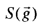
- there are reconstruction algorithms for generating compressedapproximations of a 3D image of an object. These reconstructions are made by minimising a criterion of the form


- there are time transforms Ht for the decomposition of a series of two 3D images g according to


- To achieve this aim, the invention is based on the following hypotheses:
- The variations introduced by injection of the contrast product into the vascular network are compressible, either because they are limited spatially (for example to vascular tree), or because of simple structure (for example constant by pieces for diffused contrast in the tissue).
- A corollary hypothesis is that the parts not affected by injection of the contrast product are redundant and must be reconstructed from the set of available data.
- The time formulation of acquisition with and without contrast product defines a time transform Ht from which to apply a spatial compression restriction (Φ xyz of the constituents of the time transform. The type of spatial compression (transform in wavelets, gradient, identity,...) is defined independently for each constituent (for example gradient for one and identity for the other). In particular, one of the constituents cannot be compressible, and the transform which it is associated with is then zero.
- Therefore, a first aspect of the invention is a method for processing a sequence of a plurality of 2D projection images of an object of interest, acquired by means of a medical imaging system comprising a source of X-rays, the source being adapted to shift around the object, the method comprising the following steps:
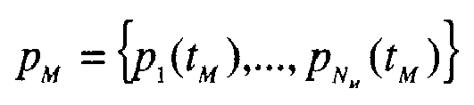
- obtaining NM 2D projection images

- iterative treatment of the projection images po and pM by minimising relatively to a sequence of 3D image(s) g = {g(to ), g(tM )} of the functional:

where -

-


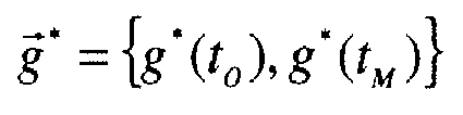
- λ is a compressibility parameter; the solution of minimising being a set of 3D image(s)
- Other aspects of the method according to the first aspect of the invention are the following:
- - The minimising consists of defining a decreasing series of degrees of compressibility


where A λ is the iteration of an algorithm permitting the minimising of


- - time decomposition Ht is the Haar transform defined by h α = g(to )+g(tM ) and hδ = g (to ) - g (tM ) ;
- - Φ xyz is such that


- - Φ xyz is such that


- - the initial sequence

- - the pluralities of acquisitions {α M,1,...,α M,Nµ } and {α 0,1,...,α0,No } contain two sub-assemblies of N angles each

angle 0<ϕ<Δθ, or: ∀i∈{1,...,N} β M,i =iΔθ |β M,i - β o,i |=ϕ; - - angular offset ϕ is equal to the semi-pitch sampling, or ϕ = Δθ/2.
- A second aspect of the invention is a medical imaging system comprising: an acquisition system comprising a source of radiation, a sensor, for the acquisition of a plurality of 2D projection images of an object; storage means of the 2D projection images acquired; a system for the treatment of the 2D projection images acquired designed to utilise a method according to the first aspect of the invention.
- A third aspect of the invention is a computer program product comprising programming code instructions for executing steps of the method according to the first aspect of the invention.
- Other characteristics and advantages of the invention will emerge from the following description which is purely illustrative and non-limiting and must be considered in conjunction with the attached diagrams, in which, apart from
Figure 1 already discussed: -
Figure 2 schematically illustrates a medical imaging system according to the invention; -
Figure 3 is a block diagram of the process of the invention; -
Figure 4 schematically illustrates steps of the process of the invention. -
Figure 2 schematically illustrates amedical imaging system 100 for the acquisition of 2D projection images for the reconstruction of a 3D image of an organ. Such a system is used especially for the detection and characterisation of stenoses in vessels. - The
medical imaging system 100 comprises asupport 1 for receiving a patient 12 to be examined, asource 11 designed to emit abeam 10 of X-rays, adetector 13 arranged opposite thesource 11 and configured to detect the X-rays emitted by thesource 11, acontrol unit 6, a storage unit 7 and adisplay unit 8. - The
source 11 of X-rays and thedetector 13 are connected for example by means of an arch 15. - The
detector 13 can be a semi-conductor image sensor comprising for example caesium phosphorous iodide (scintillater) on a matrix of transistor/photodiode of amorphous silicon. Other adequate detectors are: a CCD sensor, a direct digital detector which directly converts X-rays into digital signals. Thedetector 13 illustrated inFigure 2 is planar and defines a flat image surface, while other geometries can naturally be suitable. - The
control unit 6 controls the acquisition by fixing several parameters such as the dose of radiation to be emitted by the X-ray source and the positioning of thesource 11 and of thedetector 13. It is connected to the arch 15 by wire or wireless connection. - The
control unit 6 can comprise a reading device (not shown), for example a disc reader, a CD-ROM, DVD-ROM reader, or connection ports for reading the instructions of the process for treating an instruction medium (not shown), such as a diskette, a CD-ROM, DVD-ROM, or USB flash drive or more generally by any removable memory medium or even via a network connection. - The storage unit 7 is connected to the
control unit 6 for recording parameters and acquired images. It is possible to ensure that the storage unit 7 is located inside thecontrol unit 6 or outside it. - The storage unit 7 can be formed by a hard drive or SSD, or any other removable and rewritable storage means (USB flash drives, memory cards etc.). The storage unit 7 can be ROM/RAM memory of the
control unit 6, a USB flash drive, a memory card, central server memory. - The
display unit 8 is connected to thecontrol unit 6 for displaying the acquired images and/or information on the acquisition control parameters. - The
display unit 8 can be for example a computer screen, a monitor, a flat screen, plasma screen or any type of display device of known type. - Such a
display unit 8 allows a practitioner to control reconstruction and/or display of the 2D images acquired. - The
medical imaging system 100 is coupled to aprocessing system 200. Theprocessing system 200 comprises acalculation unit 9 andstorage unit 10. - The
processing system 200 receives the images acquired and stored in the unit memory 4 of themedical imaging system 100 from which it makes a certain number of treatments (see hereinafter), for example reconstruction of a 3D image from 2D images. - Transmission of data from the storage unit 4 of the
medical imaging system 100 to thecalculation unit 9 of theprocessing system 200 can be done over an internal or external information network or by means of any adequate physical memory medium such as diskettes, CD-ROM, DVD-ROM, external hard drive, USB flash drive, SD card, etc. - The
calculation unit 9 is for example a computer or computers, a processor or processors, a microcontroller or microcontrollers, a microcomputer or microcomputers, a programmable automaton or automatons, a specific application integrated circuit or circuits, other programmable circuits, or other devices including a computer such as a workstation. - By way of variant, the
calculator 9 can comprise a reading device (not shown), for example a disc reader, a CD-ROM, DVD-ROM reader, or connection ports for reading the instructions of the process for treating an instruction medium (not shown), such as a diskette, a CD-ROM, DVD-ROM, or USB flash drive or more generally by any removable memory medium or even via a network connection. - Also, the processing system comprises a
storage unit 14 for storing data generated by thecalculation unit 9. - The
calculation unit 9 can be connected to the display unit 8 (as inFigure 2 ) or else to another display unit (not shown). - The image processing method is for example implemented in the
treatment unit 200 of the medical imaging system illustrated inFigure 2 . - The image processing method reconstructs a sequence of two 3D images
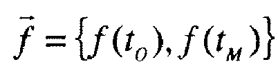
- For each time, there is a set of images of 2D projections p(tn ) with tn element of {to ,tM }, obtained by means of the medical imaging system moving according to a trajectory about the object in motion (commonly rotation, also known as spin). This trajectory can be different according to the time in question.
-
Figure 3 shows the acquisition of sets of 2D projection images
object 12 with and without contrast product. InFigure 3 , the greyed object corresponds to the object in which a contrast product was injected by means of aninjection device 14 of contrast product. - The sets of 2D projection images

storage unit 14 of theprocessing unit 200 of themedical imaging system 100 and treatment of 2D projection images is carried out in thecalculator 9 of theprocessing unit 200 of the medical imaging system. - Each plurality of sequences of 2D projection images p(tn ) is such that R(tn )f(t n ) = p(tn ). R = diag{R(tn )} for tn ∈ {to ,tM } is the projection operator, diagonal by block, which models sampling conducted by the medical imaging system during acquisition with and without contrast product. It verifies

- In current practice, the choice R(to ) = R(tM ) is privileged, for lack of adequate reconstruction. The reconstructed 3D images are affected by sub-sampling striae. The aim of the invention is to propose a reconstruction method where sub-sampling can be compensated by a priori mathematics which makes it an advantage to have R(to ) ≠ R(tM ) and thus increases the contrast resolution of all reconstructions.
- For each time tn ∈ {to , tM } of the object, the functional of the least squares following are defined:

where ∥ ∥2 symbolises the Euclidian standard known as L2 and g a 3D image. The composite functional associated with for g = {g(to ), g(tM )} is defined:
- The minimising relative to


g *(to ) is however considerably degraded by the reduced number of projection images contained in the sequence of images p(to ). The image g*(tM ) is also degraded if the number of 2D projections of p(tM ) is the same as for p(to ), as is the case in common practice which minimises the total dose of examination. - The document [Riddell C, Savi A, Gilardi MC, Fazio F, "Frequency weighted least squares reconstruction of truncated transmission SPECT data. " IEEE Trans. Nucl. Sci. 43(4):2292-8 ] and [Thibault JB, Sauer KD, Bouman CA, Hsieh J., "A three-dimensional statistical approach to improved image quality for multi-slice helical CT. " Med Phys. 34(11):4526-44 ] contains for example functionals of least weighted squares alternative to the definition of Q(g,tn ) hereinabove.
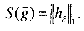
- A restriction of parsimony is also defined

where ∥ ∥1, symbolises the standard known as L1 and Ht is a decomposition time such that


- The corollary of the compressibility hypothesis linked to injection is a redundancy hypothesis of the information not affected by injection. The aim of decomposition Ht is to combine the mask and opacified 3D images so that the redundant parts, in other words the parts not affected by the contrast product and therefore common to the two images, are determined from the information available at the same time in p(tM ) and p(to ).
- Integration of measurements and of the compressibility hypothesis is done by defining the functional:

- A step of the treatment process consists of determining a sequence of images


- An iterative convex optimisation algorithm for minimising
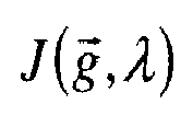
- We note A λ the iteration for minimising of


and in particular such that
- Current practice is fixing a priori an optimal value λ* of λ. This additional knowledge can be circumvented by a process of degressive restriction, that is, by definition of a decreasing sequence of degrees of compressibility Λ = {λ1,...,λΞ} such that λ1 >...> λΞ ≥ 0 for which


- To explain the unfolding of the process for obtaining


- Next,
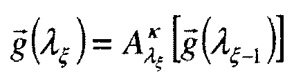
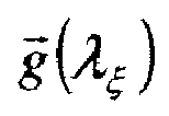


- The number of approximations Ξ and the number of iterations by approximation κ are fixed such that they form the best compromise between the quality of


- As a variant, the number of iterations κ is advantageously selected depending on the degree of compressibility λξ and inversely proportional to the latter.
- The sequence of 3D images

- Transforms and algorithms illustrating the invention as described are explained. The minimising iteration A λ of


where:



- In addition, if Ht is defined by the Haar transform itself defined by h α = g(to ) + g(tM ) and hδ = g(to ) - g(tM ), it is clear that h δ is the subtracted 3D image. If the hypothesis is made that h δ contains only contrast vessels, h δ is naturally parsimonious and Φ xyz can be defined such that


- Alternatively,


- These two choices are valid irrespectively of the definitions of R(tn ). However, if R(tM ) samples a circular trajectory with an angular pitch δθ, and if R(to) samples a circular trajectory with the same angular pitch δθ, it is advantageous with this invention to take R(tM)≠R(to ) and offsets of δθ/2 so that the operator R = diag{R(to ),R(tM )} corresponds to a sampling of a circular trajectory with an angular pitch of δθ/2. This choice doubles the angular sampling for the same total number of projections (and therefore the same dose of X-rays) relative to the current common case where R = R(tM ) = R(to ). More generally, if

angle 0 < ϕ < Δθ, or: ∀i ∈ {1,..., N} β M,i = iΔθ |β M,i - β0,i | = ϕ. - The treatment process of radiological images can be advantageously implemented as a computer program comprising machine instructions for executing the process.
Claims (10)
- A method for processing a sequence of a plurality of 2D projection images of an object of interest, acquired by means of a medical imaging system comprising a source of X-rays, the source being adapted to move around the object, the method comprising the following steps:- obtaining (S1) NM 2D projection images


 - iterative treatment (S2) of the projection images po and pM by minimising relative to a sequence of 3D images g = {g(to ), g(tM )} of the functional:
where- -
-


 - λ is a parameter of compressibility;the minimising solution being a set of 3D images

- The method as claimed in claim 1, in which minimising consists of defining a decreasing sequence of degrees of compressibility Λ = {λ1,...,λΞ} such as λ1 >...> λΞ ≥ 0 for which the estimation


where A λ is the iteration of an algorithm for the minimising of


- The method as claimed in any one of the preceding claims, in which Ht is the Haar transform defined by


- The method as claimed in any one of the preceding claims, in which Φ xyz is such that

- The method as claimed in any one of the preceding claims, in which Φ xyz is such that


- The method as claimed in any one of the preceding claims, in which the initial sequence

- The method as claimed in any one of the preceding claims, in which the pluralities of acquisitions {α M,1 ,...,α M,NM } and {α 0,1,...,α 0,No} contain two sub-assemblies of N angles each {β M,1,...,β M,N } ⊂ {α M,1,...,α M,NM } and

- The method as claimed in any one of the preceding claims, in which the angular offset ϕ is equal to the semi-pas of sampling, or ϕ = Δθ/2.
- A medical imaging system comprising:- an acquisition unit comprising a source of radiation, a sensor for the acquisition of a plurality of 2D projection images of an object;- a processing unit of acquired 2D projection images for executing a method as claimed in any one of the preceding claims.
- A computer program product comprising program code instructions for executing the steps of the method as claimed in any one of claims 1 to 7.
Applications Claiming Priority (1)
| Application Number | Priority Date | Filing Date | Title |
|---|---|---|---|
| FR1061185A FR2969793B1 (en) | 2010-12-23 | 2010-12-23 | TOMOGRAPHIC RECONSTRUCTION OF AN OBJECT IN MOTION |
Publications (2)
| Publication Number | Publication Date |
|---|---|
| EP2469471A1 true EP2469471A1 (en) | 2012-06-27 |
| EP2469471B1 EP2469471B1 (en) | 2013-08-21 |
Family
ID=43827379
Family Applications (1)
| Application Number | Title | Priority Date | Filing Date |
|---|---|---|---|
| EP11193790.0A Not-in-force EP2469471B1 (en) | 2010-12-23 | 2011-12-15 | Tomographic reconstruction of an object in motion |
Country Status (4)
| Country | Link |
|---|---|
| US (1) | US9058688B2 (en) |
| EP (1) | EP2469471B1 (en) |
| CN (1) | CN102599927B (en) |
| FR (1) | FR2969793B1 (en) |
Families Citing this family (1)
| Publication number | Priority date | Publication date | Assignee | Title |
|---|---|---|---|---|
| US10147171B2 (en) * | 2016-09-21 | 2018-12-04 | General Electric Company | Systems and methods for generating subtracted images |
Citations (1)
| Publication number | Priority date | Publication date | Assignee | Title |
|---|---|---|---|---|
| US20090161932A1 (en) * | 2007-12-20 | 2009-06-25 | Guang-Hong Chen | Method For Prior Image Constrained Image Reconstruction |
Family Cites Families (6)
| Publication number | Priority date | Publication date | Assignee | Title |
|---|---|---|---|---|
| JP5190825B2 (en) | 2006-11-13 | 2013-04-24 | 国立大学法人京都工芸繊維大学 | Image reconstruction apparatus, image reconstruction method, image reconstruction program, and CT apparatus |
| AR057580A1 (en) | 2006-11-14 | 2007-12-05 | Tomografia De Hormigon Armado | METHOD AND PROVISION TO IMPROVE TOMOGRAPHIC DETERMINATIONS THROUGH RADIATIONS, ESPECIALLY APPROPRIATE FOR STEEL BARS IN THE REINFORCED CONCRETE |
| DE102007044406A1 (en) * | 2007-09-18 | 2009-03-19 | Siemens Ag | Registration method with circulation-dependent three-dimensional representation of a vascular tree |
| DE102008007830A1 (en) | 2008-02-07 | 2009-08-13 | Siemens Aktiengesellschaft | Three dimension-data set image reconstruction method for object i.e. patient heart, involves reconstructing object specified information consisting of three dimension image dataset recorded by imaging method or modality |
| US8184890B2 (en) | 2008-12-26 | 2012-05-22 | Three Palm Software | Computer-aided diagnosis and visualization of tomosynthesis mammography data |
| JP5224057B2 (en) | 2009-03-31 | 2013-07-03 | 株式会社島津製作所 | X-ray tomography equipment |
-
2010
- 2010-12-23 FR FR1061185A patent/FR2969793B1/en not_active Expired - Fee Related
-
2011
- 2011-12-15 EP EP11193790.0A patent/EP2469471B1/en not_active Not-in-force
- 2011-12-16 US US13/328,427 patent/US9058688B2/en not_active Expired - Fee Related
- 2011-12-23 CN CN201110463248.8A patent/CN102599927B/en not_active Expired - Fee Related
Patent Citations (1)
| Publication number | Priority date | Publication date | Assignee | Title |
|---|---|---|---|---|
| US20090161932A1 (en) * | 2007-12-20 | 2009-06-25 | Guang-Hong Chen | Method For Prior Image Constrained Image Reconstruction |
Non-Patent Citations (6)
| Title |
|---|
| AFONSO MV; BIOUCAS-DIAS JM; FIGUEIREDO MA.: "Fast image recovery using variable splitting and constrained optimization", IEEE TRANS IMAGE PROCESS., pages 2345 - 56 |
| BECK A; TEBOULLE M.: "Fast gradient-based algorithms for constrained total variation image denoising and deblurring problems", IEEE TRANS. IMAGE PROCESS., vol. 18, no. 11, pages 2419 - 34, XP011270810, DOI: doi:10.1109/TIP.2009.2028250 |
| CHEN GUANG-HONG ET AL: "Prior image constrained compressed sensing (PICCS): A method to accurately reconstruct dynamic CT images from highly undersampled projection data sets", MEDICAL PHYSICS, AIP, MELVILLE, NY, US, vol. 35, no. 2, 28 January 2008 (2008-01-28), pages 660 - 663, XP012115917, ISSN: 0094-2405, DOI: 10.1118/1.2836423 * |
| MARK SUPANICH ET AL: "Radiation dose reduction in time-resolved CT angiography using highly constrained back projection reconstruction; Radiation dose reduction in time-resolved CTA using HYPR reconstruction", PHYSICS IN MEDICINE AND BIOLOGY, TAYLOR AND FRANCIS LTD. LONDON, GB, vol. 54, no. 14, 21 July 2009 (2009-07-21), pages 4575 - 4593, XP020158912, ISSN: 0031-9155 * |
| RIDDELL C; SAVI A; GILARDI MC; FAZIO F: "Frequency weighted least squares reconstruction of truncated transmission SPECT data", IEEE TRANS. NUCL. SCI., vol. 43, no. 4, pages 2292 - 8, XP011040593, DOI: doi:10.1109/23.531894 |
| THIBAULT JB; SAUER KD; BOUMAN CA; HSIEH J.: "A three-dimensional statistical approach to improved image quality for multi-slice helical CT.", MED PHYS., vol. 34, no. 11, pages 4526 - 44 |
Also Published As
| Publication number | Publication date |
|---|---|
| EP2469471B1 (en) | 2013-08-21 |
| FR2969793B1 (en) | 2013-01-11 |
| US20120163532A1 (en) | 2012-06-28 |
| FR2969793A1 (en) | 2012-06-29 |
| CN102599927B (en) | 2016-06-29 |
| CN102599927A (en) | 2012-07-25 |
| US9058688B2 (en) | 2015-06-16 |
Similar Documents
| Publication | Publication Date | Title |
|---|---|---|
| Gong et al. | Iterative PET image reconstruction using convolutional neural network representation | |
| JP6855223B2 (en) | Medical image processing device, X-ray computer tomographic imaging device and medical image processing method | |
| US8682415B2 (en) | Method and system for generating a modified 4D volume visualization | |
| US9589336B2 (en) | Reconstruction of image data by means of contour data | |
| KR101728046B1 (en) | Tomography apparatus and method for reconstructing a tomography image thereof | |
| US10213179B2 (en) | Tomography apparatus and method of reconstructing tomography image | |
| CN111540025B (en) | Predict images for image processing | |
| US9070181B2 (en) | System and method for extracting features of interest from an image | |
| EP1522045B1 (en) | Motion artifact correction of tomographical images | |
| US20110033097A1 (en) | Ct image reconstruction for improving temporal resolution in cardio ct | |
| US11978137B2 (en) | Generating reformatted views of a three-dimensional anatomy scan using deep-learning estimated scan prescription masks | |
| KR101665513B1 (en) | Computer tomography apparatus and method for reconstructing a computer tomography image thereof | |
| EP4350629A1 (en) | Artifact-driven data synthesis in computed tomography | |
| JP6486953B2 (en) | Method for segmenting motion structure in image data, target motion structure segmenter, and storage medium | |
| KR20160120963A (en) | Tomography apparatus and method for reconstructing a tomography image thereof | |
| US20120230569A1 (en) | Tomographic processing method with a small number of projections of a contrasted object | |
| US20100195888A1 (en) | Ct image reconstruction of a moving examination object | |
| US20120114207A1 (en) | Tomographic reconstruction of a moving object | |
| KR101812659B1 (en) | Tomography apparatus and method for reconstructing a tomography image thereof | |
| EP2469471B1 (en) | Tomographic reconstruction of an object in motion | |
| Şın et al. | Monte Carlo simulation of PET/MR scanner and assessment of motion correction strategies | |
| Manhart et al. | Iterative denoising algorithms for perfusion C-arm CT with a rapid scanning protocol | |
| Passand | Quality assessment of clinical thorax CT images | |
| Li | Data Consistency Driven CT Image Reconstruction | |
| Ketcha | Medical Image Registration: Statistical Models of Performance in Relation to the Statistical Characteristics of the Image Data |
Legal Events
| Date | Code | Title | Description |
|---|---|---|---|
| AK | Designated contracting states |
Kind code of ref document: A1 Designated state(s): AL AT BE BG CH CY CZ DE DK EE ES FI FR GB GR HR HU IE IS IT LI LT LU LV MC MK MT NL NO PL PT RO RS SE SI SK SM TR |
|
| AX | Request for extension of the european patent |
Extension state: BA ME |
|
| PUAI | Public reference made under article 153(3) epc to a published international application that has entered the european phase |
Free format text: ORIGINAL CODE: 0009012 |
|
| 17P | Request for examination filed |
Effective date: 20130102 |
|
| GRAP | Despatch of communication of intention to grant a patent |
Free format text: ORIGINAL CODE: EPIDOSNIGR1 |
|
| RIC1 | Information provided on ipc code assigned before grant |
Ipc: G06T 11/00 20060101AFI20130228BHEP |
|
| GRAS | Grant fee paid |
Free format text: ORIGINAL CODE: EPIDOSNIGR3 |
|
| GRAA | (expected) grant |
Free format text: ORIGINAL CODE: 0009210 |
|
| AK | Designated contracting states |
Kind code of ref document: B1 Designated state(s): AL AT BE BG CH CY CZ DE DK EE ES FI FR GB GR HR HU IE IS IT LI LT LU LV MC MK MT NL NO PL PT RO RS SE SI SK SM TR |
|
| REG | Reference to a national code |
Ref country code: GB Ref legal event code: FG4D |
|
| REG | Reference to a national code |
Ref country code: CH Ref legal event code: EP |
|
| REG | Reference to a national code |
Ref country code: AT Ref legal event code: REF Ref document number: 628477 Country of ref document: AT Kind code of ref document: T Effective date: 20130915 |
|
| REG | Reference to a national code |
Ref country code: IE Ref legal event code: FG4D |
|
| REG | Reference to a national code |
Ref country code: DE Ref legal event code: R096 Ref document number: 602011002704 Country of ref document: DE Effective date: 20131017 |
|
| REG | Reference to a national code |
Ref country code: NL Ref legal event code: T3 |
|
| REG | Reference to a national code |
Ref country code: AT Ref legal event code: MK05 Ref document number: 628477 Country of ref document: AT Kind code of ref document: T Effective date: 20130821 |
|
| REG | Reference to a national code |
Ref country code: LT Ref legal event code: MG4D |
|
| PG25 | Lapsed in a contracting state [announced via postgrant information from national office to epo] |
Ref country code: HR Free format text: LAPSE BECAUSE OF FAILURE TO SUBMIT A TRANSLATION OF THE DESCRIPTION OR TO PAY THE FEE WITHIN THE PRESCRIBED TIME-LIMIT Effective date: 20130821 Ref country code: IS Free format text: LAPSE BECAUSE OF FAILURE TO SUBMIT A TRANSLATION OF THE DESCRIPTION OR TO PAY THE FEE WITHIN THE PRESCRIBED TIME-LIMIT Effective date: 20131221 Ref country code: CY Free format text: LAPSE BECAUSE OF FAILURE TO SUBMIT A TRANSLATION OF THE DESCRIPTION OR TO PAY THE FEE WITHIN THE PRESCRIBED TIME-LIMIT Effective date: 20130828 Ref country code: LT Free format text: LAPSE BECAUSE OF FAILURE TO SUBMIT A TRANSLATION OF THE DESCRIPTION OR TO PAY THE FEE WITHIN THE PRESCRIBED TIME-LIMIT Effective date: 20130821 Ref country code: PT Free format text: LAPSE BECAUSE OF FAILURE TO SUBMIT A TRANSLATION OF THE DESCRIPTION OR TO PAY THE FEE WITHIN THE PRESCRIBED TIME-LIMIT Effective date: 20131223 Ref country code: SE Free format text: LAPSE BECAUSE OF FAILURE TO SUBMIT A TRANSLATION OF THE DESCRIPTION OR TO PAY THE FEE WITHIN THE PRESCRIBED TIME-LIMIT Effective date: 20130821 Ref country code: NO Free format text: LAPSE BECAUSE OF FAILURE TO SUBMIT A TRANSLATION OF THE DESCRIPTION OR TO PAY THE FEE WITHIN THE PRESCRIBED TIME-LIMIT Effective date: 20131121 Ref country code: AT Free format text: LAPSE BECAUSE OF FAILURE TO SUBMIT A TRANSLATION OF THE DESCRIPTION OR TO PAY THE FEE WITHIN THE PRESCRIBED TIME-LIMIT Effective date: 20130821 |
|
| PG25 | Lapsed in a contracting state [announced via postgrant information from national office to epo] |
Ref country code: PL Free format text: LAPSE BECAUSE OF FAILURE TO SUBMIT A TRANSLATION OF THE DESCRIPTION OR TO PAY THE FEE WITHIN THE PRESCRIBED TIME-LIMIT Effective date: 20130821 Ref country code: SI Free format text: LAPSE BECAUSE OF FAILURE TO SUBMIT A TRANSLATION OF THE DESCRIPTION OR TO PAY THE FEE WITHIN THE PRESCRIBED TIME-LIMIT Effective date: 20130821 Ref country code: GR Free format text: LAPSE BECAUSE OF FAILURE TO SUBMIT A TRANSLATION OF THE DESCRIPTION OR TO PAY THE FEE WITHIN THE PRESCRIBED TIME-LIMIT Effective date: 20131122 Ref country code: LV Free format text: LAPSE BECAUSE OF FAILURE TO SUBMIT A TRANSLATION OF THE DESCRIPTION OR TO PAY THE FEE WITHIN THE PRESCRIBED TIME-LIMIT Effective date: 20130821 Ref country code: FI Free format text: LAPSE BECAUSE OF FAILURE TO SUBMIT A TRANSLATION OF THE DESCRIPTION OR TO PAY THE FEE WITHIN THE PRESCRIBED TIME-LIMIT Effective date: 20130821 Ref country code: BE Free format text: LAPSE BECAUSE OF FAILURE TO SUBMIT A TRANSLATION OF THE DESCRIPTION OR TO PAY THE FEE WITHIN THE PRESCRIBED TIME-LIMIT Effective date: 20130821 |
|
| PG25 | Lapsed in a contracting state [announced via postgrant information from national office to epo] |
Ref country code: CY Free format text: LAPSE BECAUSE OF FAILURE TO SUBMIT A TRANSLATION OF THE DESCRIPTION OR TO PAY THE FEE WITHIN THE PRESCRIBED TIME-LIMIT Effective date: 20130821 |
|
| PG25 | Lapsed in a contracting state [announced via postgrant information from national office to epo] |
Ref country code: RO Free format text: LAPSE BECAUSE OF FAILURE TO SUBMIT A TRANSLATION OF THE DESCRIPTION OR TO PAY THE FEE WITHIN THE PRESCRIBED TIME-LIMIT Effective date: 20130821 Ref country code: DK Free format text: LAPSE BECAUSE OF FAILURE TO SUBMIT A TRANSLATION OF THE DESCRIPTION OR TO PAY THE FEE WITHIN THE PRESCRIBED TIME-LIMIT Effective date: 20130821 Ref country code: CZ Free format text: LAPSE BECAUSE OF FAILURE TO SUBMIT A TRANSLATION OF THE DESCRIPTION OR TO PAY THE FEE WITHIN THE PRESCRIBED TIME-LIMIT Effective date: 20130821 Ref country code: SK Free format text: LAPSE BECAUSE OF FAILURE TO SUBMIT A TRANSLATION OF THE DESCRIPTION OR TO PAY THE FEE WITHIN THE PRESCRIBED TIME-LIMIT Effective date: 20130821 Ref country code: EE Free format text: LAPSE BECAUSE OF FAILURE TO SUBMIT A TRANSLATION OF THE DESCRIPTION OR TO PAY THE FEE WITHIN THE PRESCRIBED TIME-LIMIT Effective date: 20130821 |
|
| PG25 | Lapsed in a contracting state [announced via postgrant information from national office to epo] |
Ref country code: ES Free format text: LAPSE BECAUSE OF FAILURE TO SUBMIT A TRANSLATION OF THE DESCRIPTION OR TO PAY THE FEE WITHIN THE PRESCRIBED TIME-LIMIT Effective date: 20130821 Ref country code: IT Free format text: LAPSE BECAUSE OF FAILURE TO SUBMIT A TRANSLATION OF THE DESCRIPTION OR TO PAY THE FEE WITHIN THE PRESCRIBED TIME-LIMIT Effective date: 20130821 |
|
| PLBE | No opposition filed within time limit |
Free format text: ORIGINAL CODE: 0009261 |
|
| STAA | Information on the status of an ep patent application or granted ep patent |
Free format text: STATUS: NO OPPOSITION FILED WITHIN TIME LIMIT |
|
| 26N | No opposition filed |
Effective date: 20140522 |
|
| PG25 | Lapsed in a contracting state [announced via postgrant information from national office to epo] |
Ref country code: LU Free format text: LAPSE BECAUSE OF FAILURE TO SUBMIT A TRANSLATION OF THE DESCRIPTION OR TO PAY THE FEE WITHIN THE PRESCRIBED TIME-LIMIT Effective date: 20131215 |
|
| REG | Reference to a national code |
Ref country code: DE Ref legal event code: R097 Ref document number: 602011002704 Country of ref document: DE Effective date: 20140522 |
|
| REG | Reference to a national code |
Ref country code: IE Ref legal event code: MM4A |
|
| REG | Reference to a national code |
Ref country code: FR Ref legal event code: ST Effective date: 20140829 |
|
| PG25 | Lapsed in a contracting state [announced via postgrant information from national office to epo] |
Ref country code: IE Free format text: LAPSE BECAUSE OF NON-PAYMENT OF DUE FEES Effective date: 20131215 |
|
| PG25 | Lapsed in a contracting state [announced via postgrant information from national office to epo] |
Ref country code: FR Free format text: LAPSE BECAUSE OF NON-PAYMENT OF DUE FEES Effective date: 20131231 |
|
| PG25 | Lapsed in a contracting state [announced via postgrant information from national office to epo] |
Ref country code: MC Free format text: LAPSE BECAUSE OF FAILURE TO SUBMIT A TRANSLATION OF THE DESCRIPTION OR TO PAY THE FEE WITHIN THE PRESCRIBED TIME-LIMIT Effective date: 20130821 |
|
| PG25 | Lapsed in a contracting state [announced via postgrant information from national office to epo] |
Ref country code: SM Free format text: LAPSE BECAUSE OF FAILURE TO SUBMIT A TRANSLATION OF THE DESCRIPTION OR TO PAY THE FEE WITHIN THE PRESCRIBED TIME-LIMIT Effective date: 20130821 |
|
| PG25 | Lapsed in a contracting state [announced via postgrant information from national office to epo] |
Ref country code: BG Free format text: LAPSE BECAUSE OF FAILURE TO SUBMIT A TRANSLATION OF THE DESCRIPTION OR TO PAY THE FEE WITHIN THE PRESCRIBED TIME-LIMIT Effective date: 20130821 Ref country code: RS Free format text: LAPSE BECAUSE OF FAILURE TO SUBMIT A TRANSLATION OF THE DESCRIPTION OR TO PAY THE FEE WITHIN THE PRESCRIBED TIME-LIMIT Effective date: 20131121 Ref country code: HU Free format text: LAPSE BECAUSE OF FAILURE TO SUBMIT A TRANSLATION OF THE DESCRIPTION OR TO PAY THE FEE WITHIN THE PRESCRIBED TIME-LIMIT; INVALID AB INITIO Effective date: 20111215 Ref country code: MK Free format text: LAPSE BECAUSE OF FAILURE TO SUBMIT A TRANSLATION OF THE DESCRIPTION OR TO PAY THE FEE WITHIN THE PRESCRIBED TIME-LIMIT Effective date: 20130821 |
|
| REG | Reference to a national code |
Ref country code: CH Ref legal event code: PL |
|
| PG25 | Lapsed in a contracting state [announced via postgrant information from national office to epo] |
Ref country code: MT Free format text: LAPSE BECAUSE OF FAILURE TO SUBMIT A TRANSLATION OF THE DESCRIPTION OR TO PAY THE FEE WITHIN THE PRESCRIBED TIME-LIMIT Effective date: 20130821 |
|
| PG25 | Lapsed in a contracting state [announced via postgrant information from national office to epo] |
Ref country code: LI Free format text: LAPSE BECAUSE OF NON-PAYMENT OF DUE FEES Effective date: 20141231 Ref country code: CH Free format text: LAPSE BECAUSE OF NON-PAYMENT OF DUE FEES Effective date: 20141231 |
|
| PG25 | Lapsed in a contracting state [announced via postgrant information from national office to epo] |
Ref country code: TR Free format text: LAPSE BECAUSE OF FAILURE TO SUBMIT A TRANSLATION OF THE DESCRIPTION OR TO PAY THE FEE WITHIN THE PRESCRIBED TIME-LIMIT Effective date: 20130821 |
|
| GBPC | Gb: european patent ceased through non-payment of renewal fee |
Effective date: 20151215 |
|
| PG25 | Lapsed in a contracting state [announced via postgrant information from national office to epo] |
Ref country code: GB Free format text: LAPSE BECAUSE OF NON-PAYMENT OF DUE FEES Effective date: 20151215 |
|
| PG25 | Lapsed in a contracting state [announced via postgrant information from national office to epo] |
Ref country code: AL Free format text: LAPSE BECAUSE OF FAILURE TO SUBMIT A TRANSLATION OF THE DESCRIPTION OR TO PAY THE FEE WITHIN THE PRESCRIBED TIME-LIMIT Effective date: 20130821 |
|
| PGFP | Annual fee paid to national office [announced via postgrant information from national office to epo] |
Ref country code: NL Payment date: 20191125 Year of fee payment: 9 |
|
| REG | Reference to a national code |
Ref country code: NL Ref legal event code: MM Effective date: 20210101 |
|
| PG25 | Lapsed in a contracting state [announced via postgrant information from national office to epo] |
Ref country code: NL Free format text: LAPSE BECAUSE OF NON-PAYMENT OF DUE FEES Effective date: 20210101 |
|
| PGFP | Annual fee paid to national office [announced via postgrant information from national office to epo] |
Ref country code: DE Payment date: 20211117 Year of fee payment: 11 |
|
| REG | Reference to a national code |
Ref country code: DE Ref legal event code: R119 Ref document number: 602011002704 Country of ref document: DE |
|
| PG25 | Lapsed in a contracting state [announced via postgrant information from national office to epo] |
Ref country code: DE Free format text: LAPSE BECAUSE OF NON-PAYMENT OF DUE FEES Effective date: 20230701 |