EP2469298B1 - Method and device for determining location of a target - Google Patents
Method and device for determining location of a target Download PDFInfo
- Publication number
- EP2469298B1 EP2469298B1 EP10196755.2A EP10196755A EP2469298B1 EP 2469298 B1 EP2469298 B1 EP 2469298B1 EP 10196755 A EP10196755 A EP 10196755A EP 2469298 B1 EP2469298 B1 EP 2469298B1
- Authority
- EP
- European Patent Office
- Prior art keywords
- target device
- determining
- signals
- signal power
- power
- Prior art date
- Legal status (The legal status is an assumption and is not a legal conclusion. Google has not performed a legal analysis and makes no representation as to the accuracy of the status listed.)
- Active
Links
Images



Classifications
-
- G—PHYSICS
- G01—MEASURING; TESTING
- G01S—RADIO DIRECTION-FINDING; RADIO NAVIGATION; DETERMINING DISTANCE OR VELOCITY BY USE OF RADIO WAVES; LOCATING OR PRESENCE-DETECTING BY USE OF THE REFLECTION OR RERADIATION OF RADIO WAVES; ANALOGOUS ARRANGEMENTS USING OTHER WAVES
- G01S13/00—Systems using the reflection or reradiation of radio waves, e.g. radar systems; Analogous systems using reflection or reradiation of waves whose nature or wavelength is irrelevant or unspecified
- G01S13/87—Combinations of radar systems, e.g. primary radar and secondary radar
- G01S13/878—Combination of several spaced transmitters or receivers of known location for determining the position of a transponder or a reflector
Definitions
- the present invention generally relates to the field of positioning or locating a target device.
- the target device is typically an object or a device carried or worn by a person.
- RF radio frequency
- Traditional systems are based on radio frequency (RF) signals and apply triangulation whereby the target device transmits an RF signal which needs to be received by at least three reference devices.
- the position may be estimated based on the received signal strength or the time (difference) of arrival.
- Document US2009/141591 relates to a system for extending GPS to divers and underwater vehicles.
- the navigation system comprises a location reference unit and a plurality of sub-surface beacon units.
- the system applies a dual tone method, whereby acoustic signals transmitted at different frequencies attenuate at different rates. Distinct tones can be transmitted at different power levels with a known power ratio. The power in each tone attenuates as function of the distance travelled. The distance can be computed based on difference in received power if the attenuation rate for each tone component is known.
- a distress radiolocation solution is disclosed that is based on direction finding techniques and signal strength calculations. Signal is recognized based on the duration of the pulse. Transmitters send a distress signal to a plurality of receivers that measure the received signal strength and report the signal strength to a central station that calculates a location (via traditional triangulation) based on RSSI and known location of beacons (repeaters). The central station dispatches a rescue unit. The applied processing of the signal strength measured by the repeaters makes it unnecessary to know the transmitted power.
- US6404381 presents a radio sensor device for detecting the distance and/or the speed of an object relative to the sensor device.
- the sensor device is provided with an oscillator, which can be frequency detuned through the use of a modulation function.
- the radar sensor device has a power switch, which can be driven by a power control function, for varying the transmitter power.
- the sensor device is to be operated through the use of a variable setting of the modulation and power control functions.
- the present invention aims to provide a localization or positioning system with high accuracy and independent of the applied technology.
- This invention presents a system and method used to locate a target device within a restricted area, preferably indoor, whereby "target” can be understood as an asset or a device worn by people and basically intended for locating the wearer. More specifically, the invention relates to a method and system to locate targets in any building or institution where automated location is useful and which comprises either one or a combination of larger open spaces such as a cafeteria and harsh indoor environment with many walls, such as rooms in a corridor.
- the present invention relates to a method for determining a location of a target device in connection with one or more beacons having a known position in a space, as specified in claim 1.
- the proposed solution is based on the use of trapped output powers of the transmitted signals to locate the target device which can be moving around in a space.
- This space is typically an indoor environment containing a mix of open spaces and small areas surrounded by walls such a corridor with rooms.
- the space can be a parking lot, a warehouse, an operation room, ...
- the location determination according to the invention is able to adapt itself to the specific environment.
- a successful measurement performed at lower output power has a higher level of confidence.
- a small output power has higher reliability of staying within the room so that the location method converges in the direction of a proximity measurement.
- the higher output power guarantees sufficient range and the location method converges more to a traditional triangulation.
- the achieved accuracy is significantly improved in challenging areas (with more walls) such as rooms.
- the method of the invention is deployed in a configuration comprising a target device to be located and a plurality of beacons with a known position and capable of communicating with the target device.
- the proposed method can be initiated either by the target device or by one of the beacons.
- the target device acts as a transmitter device, with which at least two signals are transmitted with a different transmit signal power. These transmitted signals are received by a receiver device, being a beacon of the plurality of beacons. For the received signals an indication of the received signal power is determined by the receiver device.
- a weighted sum of the indications of the received signal power of the at least two received signals is taken, whereby the weights of the weighted sum take into account said different transmit signal powers.
- distance information is derived, i.e. information on the distance between the transmitter and the receiver device.
- the target device acts as transmitter device, the location of said target device can then be estimated via the distance information.
- the information on the transmit signal power is comprised in the transmit signals.
- a data field in the transmit signal is kept for encapsulating this information.
- the indication of the received signal power is derived from the signal strength, e.g. the RSSI, and/or from a link quality indication.
- link quality is a metric of the current quality of the received signal.
- the link quality gives an estimate of how easily a received signal can be demodulated by accumulating the magnitude of the error between ideal constellations and the received signal. It is hence depending on the modulation format.
- RSSI is simply a signal strength indication. It does not care about the "quality” or “correctness” of the signal.
- Link quality does not care about the actual signal strength, but the signal quality often is related to signal strength. It is to be noted that the use of other parameters can be envisaged as well for the weighting by means of transmitted power.
- the target device and the beacons are preferably arranged for both transmitting and receiving, i.e. they are to be considered as transceivers.
- the receiver device transmits a response to the received signal using a signal with a transmit signal power depending on the information on the transmit signal power contained in the received signal.
- the transmit signal power applied in the response signal is determined by the transmit power used for the original message.
- the receiver device When such identity information is applied, the receiver device preferably performs a step of correlating the incoming measurements/data with the information on the identity of the transmitter device. In case of unidirectional communication, this identity information is used to link the measurements originating from the same transmitting device. In case of a bidirectional communication, the measurement data of the two links can be linked together provided that the result of the first communication (identity and indication of the received signal power) is encapsulated in the second communication signal. In one embodiment the reliability of the measurements can be estimated based on the correlation between transmitted powers and received powers, e.g. they should follow the same trend.
- a received signal is given zero weight in the estimation step if the received signal power is not in correlation with the different transmit signal powers. Indeed, such anomalies should better not be considered in the location estimation, as the reliability of information coming from such measurements is probably doubtful.
- the decision whether to discard a measurement relies on an adaptive threshold which depends on the transmit signal power and the trend of these transmit powers and receiving powers.
- a higher weight is given to a lower transmit signal power.
- a signal transmitted with a low transmit power is received, one knows that the receiver device is in a small perimeter around the transmitter. Such information has to have an important contribution to the distance information used for the location estimation.
- the estimation of the location is based on a multilateration, performed by weighing a set of error functions determined for the received signal powers.
- the weights further take into account the geometry of the space. Taking also geometry into account adds further information and improves the accuracy.
- the method as described is basically independent of the technology applied, which constitutes one of the main assets of the proposed solution. This is opposed to prior art solutions that were designed for determining location specifically with e.g. radio frequency or ultrasound communication technology.
- the invention is advantageously applied to RF technology, but also e.g. the ultrasound signals can be envisaged. In an advantageous embodiment this feature is exploited in the method by combining more than one technology for the signal communication. This further improves the reliability.
- the weights preferably further take into account the communication technology used for transmitting the plurality of signals having a different transmit signal power.
- the invention in a second aspect relates to a processing device for determining a location of a target device in connection with one or more beacons having a known position in a space, as specified in claim 7.
- the processing device receives from the receiver device the indications of the received signal power of the at least two signals transmitted by a transmitter device.
- the computing means of the processor device determines the weighted sum, derives distance information from the weighted sum and calculates an estimation of the location of the target device.
- the invention further also relates to a target device for use in the method as previously described that comprises such a processing device.
- a target device for use in the method as previously described that comprises such a processing device.
- the intelligence of the processor device is thus present in the target device.
- the processing device is integrated in a beacon.
- the invention also relates to such a beacon comprising the processor device.
- the invention relates to a system for determining a location of a target device in a space, as specified in claim 9.
- the intelligent processing device is a centrally deployed, stand-alone device capable of communicating with the target device and/or the one or more beacons.
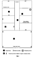
- Fig. 1 illustrates a representative set-up with both small rooms with walls and larger open spaces. Some rooms house at least one reference device (i.e., a beacon) and other not.
- a reference device i.e., a beacon
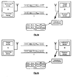
- Fig. 2 illustrates an embodiment of the invention wherein a transmitting device sends a plurality of signals at different transmit output power. These signals are received by a receiver device that determines an indication of the received signal power. The order in which the transmit output power is adjusted is not limited to the profiles shown.
- Fig. 3 illustrates an embodiment relying on bidirectional communication.
- the output power of the response is based on the transmitted output power of the initial communication link.
- Fig. 4 illustrates an embodiment relying on unidirectional communication.
- the communication can be initiated by the target device or by the reference device.
- Fig. 5 illustrates a representative embodiment where multiple reference devices are used in order to improve the accuracy of the localization method. A number of communications flows is visualized.
- Fig. 6 explains the concept of correlation of measurement data based on the transmit output power data available.
- Fig. 7 demonstrates the principles of an adaptive threshold used to interpret the measurement data. Again the transmit output power is used as parameter.
- Fig. 8 illustrates that the invention based on trapped output powers can be applied on various technologies. By combining multiple technologies, the accuracy can be further improved.
- the technology parameter can be taken into account in the weighting algorithm.
- the present invention exploits the use of different output powers of transmitted signals in order to obtain a more accurate location.
- the transmit output power in traditional systems may be adjustable, it is only done for power saving reasons and not as a means for location determination.
- a major advantage of the invention lies in its independency of the applied technology. Moreover, it can cope with an indoor environment comprising of many walls as well as large open indoor spaces and confined outdoor spaces.
- Fig. 1 illustrates a system according to one embodiment of the invention installed at an exemplary indoor environment.
- This environment includes a plurality of rooms with at least one reference device with a priori known location, a plurality of rooms with less than one reference device per room, a corridor and a large open space.
- each reference device comprises either a transmitter or a receiver, or both.
- the system includes at least one target device the location of which should be determined.
- This target device could be attached to assets, people or any item one likes to know the location of.
- the target device has a unique ID which is linked to the identity of the item.
- Target devices and reference devices are capable of communicating with each other.
- a processing device is required for determining a location of a target device.
- this processing device is a stand-alone device capable of communication with the target device and/or the one or more reference devices.
- this processing device is comprised in the target device or in a reference device.
- Both target device and reference device are able to initiate a communication sequence for locating purposes.
- Other forms of communication such as configuration, forwarding data to a server is not considered at this point.
- this communication sequence is unidirectional.
- a reference device sends signals to the target without the target device responding back to the initiating reference device or, vice versa, the target device sends signals to one or more reference devices.
- this communication sequence is bidirectional : the receiving device transmits a response back to the initiator of the sequence.
- the target device or a reference device can act as a transmitter device.
- Reference devices are referred to as devices of which the location is known to the processing device responsible of locating target devices. They can also be referred to as beacons. Both terms will be used throughout this description. Having a known location does not necessarily mean that this location has to be fixed.
- the method first comprises transmitting with a transmitter device two or more signals having a different transmit signal power.
- the transmitter device is the target device.
- these signals are received by a receiver device.
- the receiver device is a beacon of said one or more beacons and is obviously different from said transmitter device.
- the receiver device determines an indication of the received power for each of the received signals, which were transmitted with different output powers.
- the indication of the received signal power is derived from the signal strength, e.g. the RSSI, and/or from a link quality indication (LQI).
- link quality is a metric of the current quality of the received signal.
- RSSI is simply a signal strength indication and does not care about the "quality” or “correctness” of the signal.
- LQI does not care about the actual signal strength, but the signal quality often is linked to signal strength. This is because a strong signal is likely to be less affected by noise and thus will be seen as “cleaner” or "more correct” by the receiver.
- this information about the signal power should be comprised in the transmitted signal.
- a preferable way of achieving this is to make use of a data field in the transmit signal encapsulating this information.
- the transmit device sends a signal at output power P1 and encapsulates this information in a data field of the signal.
- This signal is received by a receiver device that determines e.g. by measurement an indication of the received power. Additionally, the receiver decodes the message and links the measured received power indication with the transmitted signal power as decoded from the message.
- the unique ID of the transmit device is also encapsulated in the data field.
- the communication between target device and reference device is bidirectional.
- the receiver device then transmits a response to the received signal using a signal with a transmit signal power depending on the information on the transmit signal power in the received signal.
- the transmit signal power applied in the response signal is determined by the transmit power used for the original message.
- the power is selected such that a high reliability exists that the signal arrives at its destination. Too low and too high powers are therefore avoided, which improves the efficiency of the method described in this invention.
- the invention is not limited to bidirectional communication and can be applied with only unidirectional communication as well ( Fig. 4 ).
- no response means that the signal has not arrived.
- the transmitter device can therefore adjust its output power in a more intelligent way.
- the identity information of the transmitter device which is encapsulated in the data packet is used with the incoming measurements/data in a correlation step.
- unidirectional communication e.g., communication from reference device B to target device T or from target device T to reference device D
- the measurements originating from the same transmitting device are linked with one another using this identity information.
- a bidirectional communication e.g., communication from reference device C to target device T and back or from target device T to reference device A and back
- the measurement data of the two links can be linked together under the condition that the result of the first communication (ID and indication of the received signal power) is encapsulated in the second communication signal.
- the identity information is also used to send the response (addressing).
- Correlation in this case is understood as transmit powers and receive powers which follow the same trend, e.g. when the transmit power has doubled, the same trend should be visible in the receive powers, obviously within a certain margin.
- This margin can be defined by an adaptive threshold where the threshold is defined by examining the trend line.
- Fig. 6 this is further explained by applying the method on the example of a bidirectional scenario (which is one of the possibilities from Fig. 5 ).
- a typical communication and processing flow is described next.
- Device A target or beacon
- This signal is received by device B that stores an indication of the received signal power RP meas , 1 .
- device B decodes the message and also stores the transmit signal power and both IDs of transmitting and receiving device. This results in the first line in the table shown in Fig. 6 .
- device B sends a response. Therefore it encapsulates the processed data in the data field (except for its own ID, because it has a dedicated field in this example). The output power used is dependent on the transmit signal power of the first signal.
- the response is received by device A which performs the same steps as described above to generate the second line of the table.
- the first line was stored directly from the data field of the received message.
- device A executes the correlation step.
- the processing device will verify if this trend is also visible in the indication of received signal powers RP out2 , and RP out ,1.
- the allowed deviation is determined based on an adaptive threshold.
- this threshold depends on the transmit output power and on the variance in received signal powers. In this way this threshold is adaptive, as opposed to traditional averaging approaches where outliers are filtered based on a fixed threshold. In this invention the threshold depends on properties of the transmitted signal, i.e. its output power.
- Examination of this trend can give an indication on the reliability of the measurements. Alternatively, examination of this trend can highlight an abrupt change in situation.
- Sufficient data points need to be taken into account to evaluate whether a measurement value which is far off the trend line, is a true outlier or that there is a change of the trend line due to a change in the environment, such as the target device having left the room or strongly attenuated signals due to wall penetration.
- RF technology can be combined with ultrasound. Both technologies have different propagation properties and experience a different impact of e.g. walls. Combining both trend lines can give information on whether a measurement which falls outside the trend should be considered as an outlier or as a change in environment. For example, an abrupt change only in the ultrasound measurements can be explained if the target device has left the room. If only the RF measurement displays this change, this can be considered as an outlier caused e.g. by a metal object blocking the signal.
- a received signal is given zero weight in the estimation step if the received signal power is not in line with the different transmit signal powers based of the above described processing. Indeed, such anomalies should better not be considered in the location estimation, as the reliability of information coming from such measurements is probably doubtful.
- An important step in the method of the invention concerns estimating the location of the target device via information on the distance between transmitter and receiver.
- the information is derived from a weighted sum of the indications of the received signal power, whereby the weights of the weighted sum take into account the different transmit signal powers.
- the transmitter device repeats its message a number of times to improve the robustness and to allow averaging.
- the transmitted output power is configurable as explained above in order to adapt the perimeter of reception around the node, thereby combining the advantages of proximity measurements (minimum output power) and ranging technologies.
- the interpretation of all measurements based on those signals sent with various output powers is done in a processing device which assigns weights, processes the IDs and preferably executes a multilateration algorithm in case multiple beacons are used, to further calculate the target device location.
- the relationship between received signal powers and distance information is given by the traditional path loss model which is widely known in literature. In this model there exists a logarithmic relationship between power and distance.
- the path loss coefficient should be chosen such that it takes into account the additional loss in an indoor environment.
- a dynamic path loss model can also be used to dynamically update the path loss coefficient to its environment based on the incoming measurements.
- the sum over all weights of measurements of a single reference device is normalized to one.
- the location is preferably based on proximity, performed by a weighted sum of the received signal powers based on the various transmitted signal powers.
- the algorithm advantageously starts with a transmission at minimum output power, which is subsequently gradually increased. At a certain point in time, the transmitted message will be received. In an ideal situation the next messages which are transmitted at higher power should also be received. When information of different perimeters is present, the confidence level of the measurement data of that node can be improved as explained next.
- the estimation of the location is based on a multilateration, performed by weighing a set of error functions determined for the received signal powers.
- the error functions form here indications of the received signal powers.
- the weighted multilateration is performed as follows:
- the weights further take into account the geometry of the space. Taking also geometry into account adds further information and improves the accuracy. For example if the coordinates of a third reference device lie on a straight line with two other reference devices, the weights are reduced because of the high sensitivity of the multilateration matrix.
- the method as described is basically independent of the technology applied as illustrated in Fig. 8 .
- the above described algorithm is executed in the processing device for determining a location of a target device.
- This processing device receives all indications of received powers and information required to calculate the weights and the weighted sum and multilateration in order to determine the target's location.
- the processing device can optionally be part of the target device or the reference device. Alternatively, it is a stand-alone processing device able to communicate with target device and/or one of more reference devices.
Landscapes
- Engineering & Computer Science (AREA)
- Radar, Positioning & Navigation (AREA)
- Remote Sensing (AREA)
- Computer Networks & Wireless Communication (AREA)
- Physics & Mathematics (AREA)
- General Physics & Mathematics (AREA)
- Position Fixing By Use Of Radio Waves (AREA)
- Mobile Radio Communication Systems (AREA)
Description
- The present invention generally relates to the field of positioning or locating a target device. The target device is typically an object or a device carried or worn by a person.
- A large variety of systems for positioning assets or people exist being either stationary or mobile. Such systems comprise a plurality of target devices which are attached to the items which need to be located and a plurality of reference devices the location of which is known to the system. While existing systems are functional and prove their robustness for a specific application and/or environment, they are often complex, expensive and inaccurate especially when that environment is different or changing.
- Traditional systems are based on radio frequency (RF) signals and apply triangulation whereby the target device transmits an RF signal which needs to be received by at least three reference devices. The position may be estimated based on the received signal strength or the time (difference) of arrival.
- Other systems suggest the use of infrared (IR) technology. IR radiation is limited by walls and is very power hungry. On top of this, line-of-sight communication is required which is never guaranteed in a mobile positioning system. Yet other systems propose ultrasound. This technology is less vulnerable to obstacles and is also hindered by walls and is therefore more suited for (small) zone location systems. An example is such a solution is provided in patent application
EP2065726 A2 . One issue with these kinds of acoustic localization systems is that they require high output power and high driving voltages and that an aperture is required in the target and reference devices. An additional problem is the limited range due to a strong attenuation and the very limited capacity. The waves travel very slowly and the bandwidth is very limited thereby restricting the amount of transmitted data and the time occupying the medium (which is the time no other target device can be located). - Document
US2009/141591 relates to a system for extending GPS to divers and underwater vehicles. The navigation system comprises a location reference unit and a plurality of sub-surface beacon units. The system applies a dual tone method, whereby acoustic signals transmitted at different frequencies attenuate at different rates. Distinct tones can be transmitted at different power levels with a known power ratio. The power in each tone attenuates as function of the distance travelled. The distance can be computed based on difference in received power if the attenuation rate for each tone component is known. - In
US4494119 a distress radiolocation solution is disclosed that is based on direction finding techniques and signal strength calculations. Signal is recognized based on the duration of the pulse. Transmitters send a distress signal to a plurality of receivers that measure the received signal strength and report the signal strength to a central station that calculates a location (via traditional triangulation) based on RSSI and known location of beacons (repeaters). The central station dispatches a rescue unit. The applied processing of the signal strength measured by the repeaters makes it unnecessary to know the transmitted power. -
US6404381 presents a radio sensor device for detecting the distance and/or the speed of an object relative to the sensor device. The sensor device is provided with an oscillator, which can be frequency detuned through the use of a modulation function. The radar sensor device has a power switch, which can be driven by a power control function, for varying the transmitter power. The sensor device is to be operated through the use of a variable setting of the modulation and power control functions. - The present invention aims to provide a localization or positioning system with high accuracy and independent of the applied technology.
- This invention presents a system and method used to locate a target device within a restricted area, preferably indoor, whereby "target" can be understood as an asset or a device worn by people and basically intended for locating the wearer. More specifically, the invention relates to a method and system to locate targets in any building or institution where automated location is useful and which comprises either one or a combination of larger open spaces such as a cafeteria and harsh indoor environment with many walls, such as rooms in a corridor.
- In a first aspect the present invention relates to a method for determining a location of a target device in connection with one or more beacons having a known position in a space, as specified in claim 1.The proposed solution is based on the use of trapped output powers of the transmitted signals to locate the target device which can be moving around in a space. This space is typically an indoor environment containing a mix of open spaces and small areas surrounded by walls such a corridor with rooms. Alternatively the space can be a parking lot, a warehouse, an operation room, ...
- Exploiting these different trapped output powers, the location determination according to the invention is able to adapt itself to the specific environment. A successful measurement performed at lower output power has a higher level of confidence. In smaller areas surrounded by walls, a small output power has higher reliability of staying within the room so that the location method converges in the direction of a proximity measurement. In larger areas the higher output power guarantees sufficient range and the location method converges more to a traditional triangulation. With this invention the achieved accuracy is significantly improved in challenging areas (with more walls) such as rooms.
- The method of the invention is deployed in a configuration comprising a target device to be located and a plurality of beacons with a known position and capable of communicating with the target device. The proposed method can be initiated either by the target device or by one of the beacons. The target device acts as a transmitter device, with which at least two signals are transmitted with a different transmit signal power. These transmitted signals are received by a receiver device, being a beacon of the plurality of beacons. For the received signals an indication of the received signal power is determined by the receiver device.
- Then a weighted sum of the indications of the received signal power of the at least two received signals is taken, whereby the weights of the weighted sum take into account said different transmit signal powers. From the weighted sum distance information is derived, i.e. information on the distance between the transmitter and the receiver device. As the target device acts as transmitter device, the location of said target device can then be estimated via the distance information.
- The information on the transmit signal power is comprised in the transmit signals. A data field in the transmit signal is kept for encapsulating this information.
- In a preferred embodiment of the invention the indication of the received signal power is derived from the signal strength, e.g. the RSSI, and/or from a link quality indication. Such link quality is a metric of the current quality of the received signal. The link quality gives an estimate of how easily a received signal can be demodulated by accumulating the magnitude of the error between ideal constellations and the received signal. It is hence depending on the modulation format. On the other hand, RSSI is simply a signal strength indication. It does not care about the "quality" or "correctness" of the signal. Link quality does not care about the actual signal strength, but the signal quality often is related to signal strength. It is to be noted that the use of other parameters can be envisaged as well for the weighting by means of transmitted power.
- The target device and the beacons are preferably arranged for both transmitting and receiving, i.e. they are to be considered as transceivers. In a preferred embodiment of the method of the invention the receiver device transmits a response to the received signal using a signal with a transmit signal power depending on the information on the transmit signal power contained in the received signal. Hence, the transmit signal power applied in the response signal is determined by the transmit power used for the original message. This offers the advantage that two different measurements resulting in two data pairs (transmitted power, received power) are obtained with only a single bidirectional communication link. In this way, the power is selected such that there is a high reliability that the signal arrives at its destination. Too low and too high powers are therefore avoided improving the efficiency of the method described in this invention. The invention is however not limited to bidirectional communication and can be applied with only unidirectional communication as well.
- In a scenario with more than one beacon advantageously information on the identity of the transmitter device is comprised in the transmit signals. This identity information can then be used for transmitting the response.
- When such identity information is applied, the receiver device preferably performs a step of correlating the incoming measurements/data with the information on the identity of the transmitter device. In case of unidirectional communication, this identity information is used to link the measurements originating from the same transmitting device. In case of a bidirectional communication, the measurement data of the two links can be linked together provided that the result of the first communication (identity and indication of the received signal power) is encapsulated in the second communication signal.
In one embodiment the reliability of the measurements can be estimated based on the correlation between transmitted powers and received powers, e.g. they should follow the same trend. - In one embodiment a received signal is given zero weight in the estimation step if the received signal power is not in correlation with the different transmit signal powers. Indeed, such anomalies should better not be considered in the location estimation, as the reliability of information coming from such measurements is probably doubtful. The decision whether to discard a measurement relies on an adaptive threshold which depends on the transmit signal power and the trend of these transmit powers and receiving powers.
- In a preferred embodiment a higher weight is given to a lower transmit signal power. When a signal transmitted with a low transmit power is received, one knows that the receiver device is in a small perimeter around the transmitter. Such information has to have an important contribution to the distance information used for the location estimation.
- The estimation of the location is based on a multilateration, performed by weighing a set of error functions determined for the received signal powers.
- In an advantageous embodiment the weights further take into account the geometry of the space. Taking also geometry into account adds further information and improves the accuracy.
- The method as described is basically independent of the technology applied, which constitutes one of the main assets of the proposed solution. This is opposed to prior art solutions that were designed for determining location specifically with e.g. radio frequency or ultrasound communication technology. The invention is advantageously applied to RF technology, but also e.g. the ultrasound signals can be envisaged. In an advantageous embodiment this feature is exploited in the method by combining more than one technology for the signal communication. This further improves the reliability. In such case the weights preferably further take into account the communication technology used for transmitting the plurality of signals having a different transmit signal power.
- In a second aspect the invention relates to a processing device for determining a location of a target device in connection with one or more beacons having a known position in a space, as specified in claim 7.
- Such device is indeed suitable for use in the method as set out above. The processing device receives from the receiver device the indications of the received signal power of the at least two signals transmitted by a transmitter device. The computing means of the processor device then determines the weighted sum, derives distance information from the weighted sum and calculates an estimation of the location of the target device.
- The invention further also relates to a target device for use in the method as previously described that comprises such a processing device. In this case the intelligence of the processor device is thus present in the target device.
- Alternatively, the processing device is integrated in a beacon. Hence, in one aspect the invention also relates to such a beacon comprising the processor device.
- In a further aspect the invention relates to a system for determining a location of a target device in a space, as specified in claim 9. In this scenario the intelligent processing device is a centrally deployed, stand-alone device capable of communicating with the target device and/or the one or more beacons.
-
Fig. 1 illustrates a representative set-up with both small rooms with walls and larger open spaces. Some rooms house at least one reference device (i.e., a beacon) and other not. -
Fig. 2 illustrates an embodiment of the invention wherein a transmitting device sends a plurality of signals at different transmit output power. These signals are received by a receiver device that determines an indication of the received signal power. The order in which the transmit output power is adjusted is not limited to the profiles shown. -
Fig. 3 illustrates an embodiment relying on bidirectional communication. The output power of the response is based on the transmitted output power of the initial communication link. -
Fig. 4 illustrates an embodiment relying on unidirectional communication. The communication can be initiated by the target device or by the reference device. -
Fig. 5 illustrates a representative embodiment where multiple reference devices are used in order to improve the accuracy of the localization method. A number of communications flows is visualized. -
Fig. 6 explains the concept of correlation of measurement data based on the transmit output power data available. -
Fig. 7 demonstrates the principles of an adaptive threshold used to interpret the measurement data. Again the transmit output power is used as parameter. -
Fig. 8 illustrates that the invention based on trapped output powers can be applied on various technologies. By combining multiple technologies, the accuracy can be further improved. The technology parameter can be taken into account in the weighting algorithm. - The present invention exploits the use of different output powers of transmitted signals in order to obtain a more accurate location. Although the transmit output power in traditional systems may be adjustable, it is only done for power saving reasons and not as a means for location determination. A major advantage of the invention lies in its independency of the applied technology. Moreover, it can cope with an indoor environment comprising of many walls as well as large open indoor spaces and confined outdoor spaces.
-
Fig. 1 illustrates a system according to one embodiment of the invention installed at an exemplary indoor environment. This environment includes a plurality of rooms with at least one reference device with a priori known location, a plurality of rooms with less than one reference device per room, a corridor and a large open space. In the shown embodiment each reference device comprises either a transmitter or a receiver, or both. - The system includes at least one target device the location of which should be determined. This target device could be attached to assets, people or any item one likes to know the location of. The target device has a unique ID which is linked to the identity of the item. Target devices and reference devices are capable of communicating with each other.
- Furthermore, a processing device is required for determining a location of a target device. In the embodiment shown this processing device is a stand-alone device capable of communication with the target device and/or the one or more reference devices. In another embodiment this processing device is comprised in the target device or in a reference device.
- Both target device and reference device are able to initiate a communication sequence for locating purposes. Other forms of communication such as configuration, forwarding data to a server is not considered at this point. In one embodiment this communication sequence is unidirectional. E.g. a reference device sends signals to the target without the target device responding back to the initiating reference device or, vice versa, the target device sends signals to one or more reference devices. In another embodiment this communication sequence is bidirectional : the receiving device transmits a response back to the initiator of the sequence. Hence, the target device or a reference device can act as a transmitter device.
- Reference devices are referred to as devices of which the location is known to the processing device responsible of locating target devices. They can also be referred to as beacons. Both terms will be used throughout this description. Having a known location does not necessarily mean that this location has to be fixed.
- The method first comprises transmitting with a transmitter device two or more signals having a different transmit signal power. The transmitter device is the target device.
- Secondly, these signals are received by a receiver device. The receiver device is a beacon of said one or more beacons and is obviously different from said transmitter device. The receiver device determines an indication of the received power for each of the received signals, which were transmitted with different output powers.
- The indication of the received signal power is derived from the signal strength, e.g. the RSSI, and/or from a link quality indication (LQI). Such link quality is a metric of the current quality of the received signal. On the other hand, RSSI is simply a signal strength indication and does not care about the "quality" or "correctness" of the signal. LQI does not care about the actual signal strength, but the signal quality often is linked to signal strength. This is because a strong signal is likely to be less affected by noise and thus will be seen as "cleaner" or "more correct" by the receiver.
- When the transmitter device transmits a signal at a specific configurable output power, this information about the signal power should be comprised in the transmitted signal. A preferable way of achieving this is to make use of a data field in the transmit signal encapsulating this information.
- An exemplary embodiment, shown in
Fig.2 , illustrates the above principles: the transmit device sends a signal at output power P1 and encapsulates this information in a data field of the signal. This signal is received by a receiver device that determines e.g. by measurement an indication of the received power. Additionally, the receiver decodes the message and links the measured received power indication with the transmitted signal power as decoded from the message. - When multiple devices are used, as most often occurs in a real-life configuration, the unique ID of the transmit device is also encapsulated in the data field.
- In an advantageous embodiment, illustrated in
Fig. 3 , the communication between target device and reference device is bidirectional. The receiver device then transmits a response to the received signal using a signal with a transmit signal power depending on the information on the transmit signal power in the received signal. Hence, the transmit signal power applied in the response signal is determined by the transmit power used for the original message. In this way two different measurements resulting in two data pairs (transmitted power, received power) are obtained with only a single bidirectional communication link. The power is selected such that a high reliability exists that the signal arrives at its destination. Too low and too high powers are therefore avoided, which improves the efficiency of the method described in this invention. - The invention is not limited to bidirectional communication and can be applied with only unidirectional communication as well (
Fig. 4 ). In such embodiment there is no feedback about the selected transmit signal powers to the transmitter device. Therefore it is possible that at the lowest output power the signal does not arrive at its destination while the transmitter is not being informed of this failure. In the case of bidirectional communication, no response means that the signal has not arrived. The transmitter device can therefore adjust its output power in a more intelligent way. - In a scenario with more than one beacon (see
Fig. 5 ), the identity information of the transmitter device which is encapsulated in the data packet is used with the incoming measurements/data in a correlation step.
In case of unidirectional communication (e.g., communication from reference device B to target device T or from target device T to reference device D), the measurements originating from the same transmitting device are linked with one another using this identity information.
In case of a bidirectional communication (e.g., communication from reference device C to target device T and back or from target device T to reference device A and back), the measurement data of the two links can be linked together under the condition that the result of the first communication (ID and indication of the received signal power) is encapsulated in the second communication signal. In this case the identity information is also used to send the response (addressing). - Correlation in this case is understood as transmit powers and receive powers which follow the same trend, e.g. when the transmit power has doubled, the same trend should be visible in the receive powers, obviously within a certain margin. This margin can be defined by an adaptive threshold where the threshold is defined by examining the trend line.
InFig. 6 this is further explained by applying the method on the example of a bidirectional scenario (which is one of the possibilities fromFig. 5 ). A typical communication and processing flow is described next.
Device A (target or beacon) transmits a signal at a given output power containing its ID and the value of the transmitted output power TPout,1. This signal is received by device B that stores an indication of the received signal power RPmeas,1. Next, device B decodes the message and also stores the transmit signal power and both IDs of transmitting and receiving device. This results in the first line in the table shown inFig. 6 . Next, device B sends a response. Therefore it encapsulates the processed data in the data field (except for its own ID, because it has a dedicated field in this example). The output power used is dependent on the transmit signal power of the first signal. Then, the response is received by device A which performs the same steps as described above to generate the second line of the table. The first line was stored directly from the data field of the received message. As a final step, device A executes the correlation step. For instance if the transmit signal power TPout,2 is twice TPout,1, the processing device will verify if this trend is also visible in the indication of received signal powers RPout2, and RPout,1. The allowed deviation is determined based on an adaptive threshold. - As illustrated in
Fig.7 this threshold depends on the transmit output power and on the variance in received signal powers. In this way this threshold is adaptive, as opposed to traditional averaging approaches where outliers are filtered based on a fixed threshold. In this invention the threshold depends on properties of the transmitted signal, i.e. its output power. - Examination of this trend can give an indication on the reliability of the measurements. Alternatively, examination of this trend can highlight an abrupt change in situation.
- Sufficient data points need to be taken into account to evaluate whether a measurement value which is far off the trend line, is a true outlier or that there is a change of the trend line due to a change in the environment, such as the target device having left the room or strongly attenuated signals due to wall penetration.
- Evaluation and interpretation of trends and changes can be improved when the proposed method, which as already mentioned is technology independent, is applied on multiple technologies.
- In an advantageous embodiment RF technology can be combined with ultrasound. Both technologies have different propagation properties and experience a different impact of e.g. walls. Combining both trend lines can give information on whether a measurement which falls outside the trend should be considered as an outlier or as a change in environment. For example, an abrupt change only in the ultrasound measurements can be explained if the target device has left the room. If only the RF measurement displays this change, this can be considered as an outlier caused e.g. by a metal object blocking the signal.
- In one embodiment a received signal is given zero weight in the estimation step if the received signal power is not in line with the different transmit signal powers based of the above described processing. Indeed, such anomalies should better not be considered in the location estimation, as the reliability of information coming from such measurements is probably doubtful.
- An important step in the method of the invention concerns estimating the location of the target device via information on the distance between transmitter and receiver. The information is derived from a weighted sum of the indications of the received signal power, whereby the weights of the weighted sum take into account the different transmit signal powers.
- In conventional systems the transmitter device repeats its message a number of times to improve the robustness and to allow averaging. On the contrary, in this invention the transmitted output power is configurable as explained above in order to adapt the perimeter of reception around the node, thereby combining the advantages of proximity measurements (minimum output power) and ranging technologies. The interpretation of all measurements based on those signals sent with various output powers is done in a processing device which assigns weights, processes the IDs and preferably executes a multilateration algorithm in case multiple beacons are used, to further calculate the target device location.
- When a signal with low transmit power is received, one knows that the receiving device is located in a small perimeter around the transmitter. If multiple receiver devices receive this signal, one even knows the direction based on multilateration, as will be further explained. A smaller perimeter or a closer proximity means that there is less spread on the measurements (because e.g. less obstacles can stand in the way). Therefore in a preferred embodiment a higher weight is given to a lower transmit signal power. This particular measurement will then have an important contribution to the distance information used for the location estimation.
- The relationship between received signal powers and distance information is given by the traditional path loss model which is widely known in literature. In this model there exists a logarithmic relationship between power and distance. The path loss coefficient should be chosen such that it takes into account the additional loss in an indoor environment.
- A dynamic path loss model can also be used to dynamically update the path loss coefficient to its environment based on the incoming measurements.
- As the weights are a function of the transmitted output signal power, the assignments of their value also follow the same logarithmic law.
- In a preferred embodiment the sum over all weights of measurements of a single reference device is normalized to one.
- In a situation, not according to the invention, where only one beacon is used or where only information is available from a single transmitter device (hence, a beacon or target device), the location is preferably based on proximity, performed by a weighted sum of the received signal powers based on the various transmitted signal powers. The algorithm advantageously starts with a transmission at minimum output power, which is subsequently gradually increased. At a certain point in time, the transmitted message will be received. In an ideal situation the next messages which are transmitted at higher power should also be received. When information of different perimeters is present, the confidence level of the measurement data of that node can be improved as explained next.
- An example is given for only two measurements. The idea can however be generalized, as the skilled person will readily appreciate.
- Measurement at t1 results in RSSln1,t1 corresponding to a transmitted signal from node n1 with transmit output power Pn1,t1 = P1.
- Measurement at t2 results in RSS/ n1,t2 corresponding to a transmitted signal from node n1 with transmit output power Pn1,t2 = P2.
- According to the invention, the estimation of the location is based on a multilateration, performed by weighing a set of error functions determined for the received signal powers. Hence, the error functions form here indications of the received signal powers. In this way, measurements of multiple reference node can be combined within a given time interval to improve the accuracy of the location. The more data is available, the more accurate the result becomes.
As explained above, the reliability of the measurements depends on the output power and therefore the trapped output power approach is a suitable means to assign weight to the different measurements. - The weighted multilateration is performed as follows:
- Per measurement, the error function fi,f between estimated and measured distance is defined as

where (x,y) is the position of the target device one is looking for, (xi,yi) the known position of the reference node or beacon used in that measurement and di,j a distance estimation based on the indication of the received signal power. - Apply the least squares methodology to minimize the error function F.

where wj are the weights which are proportional to the transmitted output power as described above. - In an advantageous embodiment the weights further take into account the geometry of the space. Taking also geometry into account adds further information and improves the accuracy. For example if the coordinates of a third reference device lie on a straight line with two other reference devices, the weights are reduced because of the high sensitivity of the multilateration matrix.
- The method as described is basically independent of the technology applied as illustrated in
Fig. 8 . As previously described, the use of multiple technologies was introduced for evaluation and interpretation of trends and changes of measurements performed by a receiver device. Multiple technologies can also be used in the weights, which then also take into account the communication technology applied for transmitting the variety of signals with different transmit signal power:
- The above described algorithm is executed in the processing device for determining a location of a target device. This processing device receives all indications of received powers and information required to calculate the weights and the weighted sum and multilateration in order to determine the target's location. The processing device can optionally be part of the target device or the reference device. Alternatively, it is a stand-alone processing device able to communicate with target device and/or one of more reference devices.

In this way the reliability of the average/normalized RSSI from a specific node can be iteratively improved. The weight is linked to the transmitted output power as described above.
Claims (9)
- A method for determining an indoor location of a target device in connection with a plurality of beacons having a known position in a space, the method comprising the steps of:- transmitting with a transmitter device a plurality of signals having different respective transmit signal powers, said transmitter device being said target device, and- receiving at least two of said plurality of transmitted signals with respective receiver devices, said respective receiver devices being beacons of said plurality of beacons, and determining for said at least two received signals an indication of the received signal power,characterized in that the method further comprises:- determining for each of said at least two received signals, based on a path loss model, an estimated distance between said transmitter device and said respective receiver device, yielding a set of error functions between said estimated distance and the actual distance to be determined,- assigning weights wj that take into account said different transmit signal powers, whereby a higher weight is given to a lower transmit signal power,- estimating the indoor location of said target device, based on multilateration, by weighing said set of error functions with said weights, whereby information on the transmit signal power is encapsulated in a data field comprised in said transmit signals and information on the identity of the transmitter device is comprised in said transmit signals, as follows:- defining the error function fi,j between estimated and measured distance per measurement as

for i = 1..M (#beacons) for j = 1..N (#power levels) where (x,y) is the position of the target device one is looking for, (xi ,yi ) the known position of the beacon used in that measurement and di,j a distance estimation based on the indication of the received signal power,- applying the least squares methodology to minimize the error function F
- Method for determining an indoor location as in claim 1, whereby said indication of the received signal power is derived from the signal strength and/or from a link quality indication.
- Method for determining an indoor location as in any of claims 1 to 2, whereby a received signal is given zero weight in the estimation step if the received signal power is not in correlation with the different transmit signal powers.
- Method for determining an indoor location as in any of claims 1 to 3, whereby said receiver device transmits a response with a transmit signal power depending on said information on the transmit signal power in the received signal.
- Method for determining an indoor location as in any of the previous claims, wherein said weights further take into account the geometry of the space.
- Method for determining an indoor location as in any of the previous claims, wherein said weights further take into account the communication technology used for transmitting said plurality of signals having a different transmit signal power.
- Processing device for determining an indoor location of a target device in connection with a plurality of beacons having a known position in a space, the processing device comprising- receiving means for receiving indications of the received signal power of at least two signals transmitted with different respective transmit signal powers by a target device,characterized in that said processing device further comprises:- computing means for determining for each of said at least two received signals, based on a path loss model, an estimated distance between said transmitter device and said receiving means, yielding a set of error functions between said estimated distance and the actual distance to be determined, said computing means further arranged for assigning weights wj that take into account said different transmit signal powers, whereby a higher weight is given to a lower transmit signal power, and for estimating the indoor location of said target device, based on multilateration, by weighing said set of error functions with said weights, as follows:- defining the error function fi,j between estimated and measured distance per measurement as

for i = 1..M (#beacons) for j = 1..N (#power levels) where (x,y) is the position of the target device one is looking for, (xi,yi ) the known position of the beacon used in that measurement and di,j a distance estimation based on the indication of the received signal power,- applying the least squares methodology to minimize the error function F
- Beacon for use in the method as in any of claims 1 to 6, comprising a processing device as in claim 7.
- System for determining an indoor location of a target device in a space, said system comprising- the processing device as in claim 7,- a plurality of beacons arranged for transmitting and receiving signals and a target device arranged for being in connection with said plurality of beacons and for transmitting and receiving signals, whereby said target device and said plurality beacons are arranged for determining an indication of the received signal power of a received signal and for communicating with the processing device.
Priority Applications (2)
| Application Number | Priority Date | Filing Date | Title |
|---|---|---|---|
| EP10196755.2A EP2469298B1 (en) | 2010-12-23 | 2010-12-23 | Method and device for determining location of a target |
| BE2011/0080A BE1022275B1 (en) | 2010-12-23 | 2011-02-09 | METHOD AND DEVICE FOR DETERMINING THE LOCATION OF A TARGET WHITE |
Applications Claiming Priority (1)
| Application Number | Priority Date | Filing Date | Title |
|---|---|---|---|
| EP10196755.2A EP2469298B1 (en) | 2010-12-23 | 2010-12-23 | Method and device for determining location of a target |
Publications (2)
| Publication Number | Publication Date |
|---|---|
| EP2469298A1 EP2469298A1 (en) | 2012-06-27 |
| EP2469298B1 true EP2469298B1 (en) | 2015-02-18 |
Family
ID=43618088
Family Applications (1)
| Application Number | Title | Priority Date | Filing Date |
|---|---|---|---|
| EP10196755.2A Active EP2469298B1 (en) | 2010-12-23 | 2010-12-23 | Method and device for determining location of a target |
Country Status (2)
| Country | Link |
|---|---|
| EP (1) | EP2469298B1 (en) |
| BE (1) | BE1022275B1 (en) |
Cited By (2)
| Publication number | Priority date | Publication date | Assignee | Title |
|---|---|---|---|---|
| US9746543B2 (en) | 2013-12-24 | 2017-08-29 | Televic Healthcare Nv | Localisation system |
| US10539673B2 (en) | 2016-12-30 | 2020-01-21 | Televic Healthcare Nv | False alarm avoidance system |
Families Citing this family (10)
| Publication number | Priority date | Publication date | Assignee | Title |
|---|---|---|---|---|
| CN104101861B (en) * | 2013-04-09 | 2017-01-04 | 广东美晨通讯有限公司 | Distance-measuring and positioning method and system |
| EP2889635A1 (en) * | 2013-12-24 | 2015-07-01 | Televic Healthcare NV | Localisation system |
| EP3185033B1 (en) | 2015-12-22 | 2018-09-26 | Televic Healthcare NV | Beacon apparatus and associated room lamp unit |
| GB2551347B (en) | 2016-06-13 | 2020-04-15 | Toshiba Kk | Indoor localisation using received signal quality weights |
| CN107547598B (en) * | 2016-06-27 | 2020-07-24 | 华为技术有限公司 | A positioning method, server and terminal |
| TWI708957B (en) | 2019-12-12 | 2020-11-01 | 聚眾聯合科技股份有限公司 | Dynamic power positioning method and dynamic power positioning system thereof |
| US11454695B2 (en) | 2019-12-12 | 2022-09-27 | Gunitech Corp. | Dynamic power positioning method and dynamic power positioning system thereof |
| US11265677B2 (en) | 2019-12-24 | 2022-03-01 | Gunitech Corp. | Power positioning method and power positioning device thereof |
| TWI720758B (en) * | 2019-12-24 | 2021-03-01 | 聚眾聯合科技股份有限公司 | Power positioning method and power positioning device thereof |
| CN113885061B (en) * | 2021-09-29 | 2024-12-24 | 中信科移动通信技术股份有限公司 | Radio positioning devices and systems |
Family Cites Families (4)
| Publication number | Priority date | Publication date | Assignee | Title |
|---|---|---|---|---|
| US4494119A (en) * | 1983-08-04 | 1985-01-15 | 122923 Canada Limited | Distress radiolocation method and system |
| DE19803660C2 (en) * | 1998-01-30 | 2001-07-05 | Siemens Ag | Motor vehicle radar |
| US7969822B2 (en) * | 2005-07-15 | 2011-06-28 | Estate Of Albert R. Basilico | System and method for extending GPS to divers and underwater vehicles |
| DK2065726T3 (en) | 2007-11-13 | 2012-05-21 | Uni I Oslo | High capacity ultrasonic zone localization system |
-
2010
- 2010-12-23 EP EP10196755.2A patent/EP2469298B1/en active Active
-
2011
- 2011-02-09 BE BE2011/0080A patent/BE1022275B1/en not_active IP Right Cessation
Cited By (2)
| Publication number | Priority date | Publication date | Assignee | Title |
|---|---|---|---|---|
| US9746543B2 (en) | 2013-12-24 | 2017-08-29 | Televic Healthcare Nv | Localisation system |
| US10539673B2 (en) | 2016-12-30 | 2020-01-21 | Televic Healthcare Nv | False alarm avoidance system |
Also Published As
| Publication number | Publication date |
|---|---|
| EP2469298A1 (en) | 2012-06-27 |
| BE1022275B1 (en) | 2016-03-09 |
Similar Documents
| Publication | Publication Date | Title |
|---|---|---|
| EP2469298A1 (en) | Method and device for determining location of a target | |
| JP7606458B2 (en) | SYSTEM AND METHOD USING RANGEMENT AND TRIANGULATION TO IDENTIFY THE LOCATION OF WIRELESS SENSOR NODES BASED ON RADIO FREQUENCY COMMUNICATIONS BETWEEN THE NODES AND VARIOUS RF-ENABLED DEVICES - Patent application | |
| US7233287B2 (en) | Method and system for positioning mobile units based on angle measurements | |
| US9557402B2 (en) | Indoor positioning system | |
| US9213082B2 (en) | Processing time determination for wireless position determination | |
| KR102253830B1 (en) | Positioning system | |
| Booranawong et al. | RSSI-based indoor localization using multi-lateration with zone selection and virtual position-based compensation methods | |
| EP3295207B1 (en) | Base station selection for positioning/localization based on an indication of capacity | |
| Kyritsis et al. | A BLE-based probabilistic room-level localization method | |
| JP5025675B2 (en) | Moving object detection system | |
| Garcia et al. | Wireless Sensors self-location in an Indoor WLAN environment | |
| Obreja et al. | Evaluation of an indoor localization solution based on bluetooth low energy beacons | |
| EP2952925A1 (en) | Method, device and system for indoor localization and tracking using ultra-wideband radio signals | |
| WO2019239983A1 (en) | Propagation environment recognition method and propagation environment recognition device | |
| US7209754B2 (en) | Method and apparatus for determining the location of a node in a wireless title system | |
| WO2020091590A1 (en) | A system and method for locating a device in an indoor environment | |
| JP2023510957A (en) | Likelihood-based acoustic positioning | |
| US10547964B2 (en) | Method and device for estimating accuracy of a position determination | |
| WO2013171679A1 (en) | Handheld-device-based indoor localization system and method | |
| Tian et al. | A weighted least-squares method using received signal strength measurements for WLAN indoor positioning system | |
| Yoon et al. | An efficient distance estimation method based on Bluetooth low energy and ultrasound | |
| Riesebos et al. | Smartphone-based real-time indoor positioning using BLE beacons | |
| US20060221864A1 (en) | Method and apparatus for determining a best technique to use when locating a node | |
| CN102662168A (en) | Building positioning method based on UWB (ultra-wideband) technology | |
| Källberg | RSSI based Positioning in Tunnels |
Legal Events
| Date | Code | Title | Description |
|---|---|---|---|
| AK | Designated contracting states |
Kind code of ref document: A1 Designated state(s): AL AT BE BG CH CY CZ DE DK EE ES FI FR GB GR HR HU IE IS IT LI LT LU LV MC MK MT NL NO PL PT RO RS SE SI SK SM TR |
|
| AX | Request for extension of the european patent |
Extension state: BA ME |
|
| PUAI | Public reference made under article 153(3) epc to a published international application that has entered the european phase |
Free format text: ORIGINAL CODE: 0009012 |
|
| 17P | Request for examination filed |
Effective date: 20121221 |
|
| 17Q | First examination report despatched |
Effective date: 20130131 |
|
| GRAP | Despatch of communication of intention to grant a patent |
Free format text: ORIGINAL CODE: EPIDOSNIGR1 |
|
| INTG | Intention to grant announced |
Effective date: 20141009 |
|
| RIN1 | Information on inventor provided before grant (corrected) |
Inventor name: GESQUIERE, JOHN Inventor name: STUBBE, BRECHT Inventor name: CROMBEZ, PIETER |
|
| GRAS | Grant fee paid |
Free format text: ORIGINAL CODE: EPIDOSNIGR3 |
|
| GRAA | (expected) grant |
Free format text: ORIGINAL CODE: 0009210 |
|
| AK | Designated contracting states |
Kind code of ref document: B1 Designated state(s): AL AT BE BG CH CY CZ DE DK EE ES FI FR GB GR HR HU IE IS IT LI LT LU LV MC MK MT NL NO PL PT RO RS SE SI SK SM TR |
|
| REG | Reference to a national code |
Ref country code: GB Ref legal event code: FG4D |
|
| REG | Reference to a national code |
Ref country code: CH Ref legal event code: EP |
|
| REG | Reference to a national code |
Ref country code: AT Ref legal event code: REF Ref document number: 710876 Country of ref document: AT Kind code of ref document: T Effective date: 20150315 |
|
| REG | Reference to a national code |
Ref country code: IE Ref legal event code: FG4D |
|
| REG | Reference to a national code |
Ref country code: DE Ref legal event code: R096 Ref document number: 602010022302 Country of ref document: DE Effective date: 20150402 |
|
| REG | Reference to a national code |
Ref country code: NL Ref legal event code: T3 |
|
| REG | Reference to a national code |
Ref country code: AT Ref legal event code: MK05 Ref document number: 710876 Country of ref document: AT Kind code of ref document: T Effective date: 20150218 |
|
| REG | Reference to a national code |
Ref country code: LT Ref legal event code: MG4D |
|
| PG25 | Lapsed in a contracting state [announced via postgrant information from national office to epo] |
Ref country code: NO Free format text: LAPSE BECAUSE OF FAILURE TO SUBMIT A TRANSLATION OF THE DESCRIPTION OR TO PAY THE FEE WITHIN THE PRESCRIBED TIME-LIMIT Effective date: 20150518 Ref country code: SE Free format text: LAPSE BECAUSE OF FAILURE TO SUBMIT A TRANSLATION OF THE DESCRIPTION OR TO PAY THE FEE WITHIN THE PRESCRIBED TIME-LIMIT Effective date: 20150218 Ref country code: LT Free format text: LAPSE BECAUSE OF FAILURE TO SUBMIT A TRANSLATION OF THE DESCRIPTION OR TO PAY THE FEE WITHIN THE PRESCRIBED TIME-LIMIT Effective date: 20150218 Ref country code: FI Free format text: LAPSE BECAUSE OF FAILURE TO SUBMIT A TRANSLATION OF THE DESCRIPTION OR TO PAY THE FEE WITHIN THE PRESCRIBED TIME-LIMIT Effective date: 20150218 Ref country code: ES Free format text: LAPSE BECAUSE OF FAILURE TO SUBMIT A TRANSLATION OF THE DESCRIPTION OR TO PAY THE FEE WITHIN THE PRESCRIBED TIME-LIMIT Effective date: 20150218 Ref country code: HR Free format text: LAPSE BECAUSE OF FAILURE TO SUBMIT A TRANSLATION OF THE DESCRIPTION OR TO PAY THE FEE WITHIN THE PRESCRIBED TIME-LIMIT Effective date: 20150218 |
|
| PG25 | Lapsed in a contracting state [announced via postgrant information from national office to epo] |
Ref country code: LV Free format text: LAPSE BECAUSE OF FAILURE TO SUBMIT A TRANSLATION OF THE DESCRIPTION OR TO PAY THE FEE WITHIN THE PRESCRIBED TIME-LIMIT Effective date: 20150218 Ref country code: RS Free format text: LAPSE BECAUSE OF FAILURE TO SUBMIT A TRANSLATION OF THE DESCRIPTION OR TO PAY THE FEE WITHIN THE PRESCRIBED TIME-LIMIT Effective date: 20150218 Ref country code: GR Free format text: LAPSE BECAUSE OF FAILURE TO SUBMIT A TRANSLATION OF THE DESCRIPTION OR TO PAY THE FEE WITHIN THE PRESCRIBED TIME-LIMIT Effective date: 20150519 Ref country code: AT Free format text: LAPSE BECAUSE OF FAILURE TO SUBMIT A TRANSLATION OF THE DESCRIPTION OR TO PAY THE FEE WITHIN THE PRESCRIBED TIME-LIMIT Effective date: 20150218 Ref country code: IS Free format text: LAPSE BECAUSE OF FAILURE TO SUBMIT A TRANSLATION OF THE DESCRIPTION OR TO PAY THE FEE WITHIN THE PRESCRIBED TIME-LIMIT Effective date: 20150618 |
|
| PG25 | Lapsed in a contracting state [announced via postgrant information from national office to epo] |
Ref country code: RO Free format text: LAPSE BECAUSE OF FAILURE TO SUBMIT A TRANSLATION OF THE DESCRIPTION OR TO PAY THE FEE WITHIN THE PRESCRIBED TIME-LIMIT Effective date: 20150218 Ref country code: EE Free format text: LAPSE BECAUSE OF FAILURE TO SUBMIT A TRANSLATION OF THE DESCRIPTION OR TO PAY THE FEE WITHIN THE PRESCRIBED TIME-LIMIT Effective date: 20150218 Ref country code: CZ Free format text: LAPSE BECAUSE OF FAILURE TO SUBMIT A TRANSLATION OF THE DESCRIPTION OR TO PAY THE FEE WITHIN THE PRESCRIBED TIME-LIMIT Effective date: 20150218 Ref country code: DK Free format text: LAPSE BECAUSE OF FAILURE TO SUBMIT A TRANSLATION OF THE DESCRIPTION OR TO PAY THE FEE WITHIN THE PRESCRIBED TIME-LIMIT Effective date: 20150218 Ref country code: SK Free format text: LAPSE BECAUSE OF FAILURE TO SUBMIT A TRANSLATION OF THE DESCRIPTION OR TO PAY THE FEE WITHIN THE PRESCRIBED TIME-LIMIT Effective date: 20150218 |
|
| REG | Reference to a national code |
Ref country code: DE Ref legal event code: R097 Ref document number: 602010022302 Country of ref document: DE |
|
| PG25 | Lapsed in a contracting state [announced via postgrant information from national office to epo] |
Ref country code: PL Free format text: LAPSE BECAUSE OF FAILURE TO SUBMIT A TRANSLATION OF THE DESCRIPTION OR TO PAY THE FEE WITHIN THE PRESCRIBED TIME-LIMIT Effective date: 20150218 |
|
| REG | Reference to a national code |
Ref country code: FR Ref legal event code: PLFP Year of fee payment: 6 |
|
| PLBE | No opposition filed within time limit |
Free format text: ORIGINAL CODE: 0009261 |
|
| STAA | Information on the status of an ep patent application or granted ep patent |
Free format text: STATUS: NO OPPOSITION FILED WITHIN TIME LIMIT |
|
| PG25 | Lapsed in a contracting state [announced via postgrant information from national office to epo] |
Ref country code: IT Free format text: LAPSE BECAUSE OF FAILURE TO SUBMIT A TRANSLATION OF THE DESCRIPTION OR TO PAY THE FEE WITHIN THE PRESCRIBED TIME-LIMIT Effective date: 20150218 |
|
| 26N | No opposition filed |
Effective date: 20151119 |
|
| PG25 | Lapsed in a contracting state [announced via postgrant information from national office to epo] |
Ref country code: SI Free format text: LAPSE BECAUSE OF FAILURE TO SUBMIT A TRANSLATION OF THE DESCRIPTION OR TO PAY THE FEE WITHIN THE PRESCRIBED TIME-LIMIT Effective date: 20150218 |
|
| PGFP | Annual fee paid to national office [announced via postgrant information from national office to epo] |
Ref country code: MC Payment date: 20151215 Year of fee payment: 6 |
|
| PG25 | Lapsed in a contracting state [announced via postgrant information from national office to epo] |
Ref country code: LU Free format text: LAPSE BECAUSE OF FAILURE TO SUBMIT A TRANSLATION OF THE DESCRIPTION OR TO PAY THE FEE WITHIN THE PRESCRIBED TIME-LIMIT Effective date: 20151223 |
|
| REG | Reference to a national code |
Ref country code: CH Ref legal event code: PL |
|
| GBPC | Gb: european patent ceased through non-payment of renewal fee |
Effective date: 20151223 |
|
| REG | Reference to a national code |
Ref country code: IE Ref legal event code: MM4A |
|
| PG25 | Lapsed in a contracting state [announced via postgrant information from national office to epo] |
Ref country code: CH Free format text: LAPSE BECAUSE OF NON-PAYMENT OF DUE FEES Effective date: 20151231 Ref country code: GB Free format text: LAPSE BECAUSE OF NON-PAYMENT OF DUE FEES Effective date: 20151223 Ref country code: LI Free format text: LAPSE BECAUSE OF NON-PAYMENT OF DUE FEES Effective date: 20151231 Ref country code: IE Free format text: LAPSE BECAUSE OF NON-PAYMENT OF DUE FEES Effective date: 20151223 |
|
| REG | Reference to a national code |
Ref country code: FR Ref legal event code: PLFP Year of fee payment: 7 |
|
| PG25 | Lapsed in a contracting state [announced via postgrant information from national office to epo] |
Ref country code: SM Free format text: LAPSE BECAUSE OF FAILURE TO SUBMIT A TRANSLATION OF THE DESCRIPTION OR TO PAY THE FEE WITHIN THE PRESCRIBED TIME-LIMIT Effective date: 20150218 Ref country code: HU Free format text: LAPSE BECAUSE OF FAILURE TO SUBMIT A TRANSLATION OF THE DESCRIPTION OR TO PAY THE FEE WITHIN THE PRESCRIBED TIME-LIMIT; INVALID AB INITIO Effective date: 20101223 Ref country code: BG Free format text: LAPSE BECAUSE OF FAILURE TO SUBMIT A TRANSLATION OF THE DESCRIPTION OR TO PAY THE FEE WITHIN THE PRESCRIBED TIME-LIMIT Effective date: 20150218 |
|
| PG25 | Lapsed in a contracting state [announced via postgrant information from national office to epo] |
Ref country code: CY Free format text: LAPSE BECAUSE OF FAILURE TO SUBMIT A TRANSLATION OF THE DESCRIPTION OR TO PAY THE FEE WITHIN THE PRESCRIBED TIME-LIMIT Effective date: 20150218 |
|
| PG25 | Lapsed in a contracting state [announced via postgrant information from national office to epo] |
Ref country code: MT Free format text: LAPSE BECAUSE OF FAILURE TO SUBMIT A TRANSLATION OF THE DESCRIPTION OR TO PAY THE FEE WITHIN THE PRESCRIBED TIME-LIMIT Effective date: 20150218 Ref country code: TR Free format text: LAPSE BECAUSE OF FAILURE TO SUBMIT A TRANSLATION OF THE DESCRIPTION OR TO PAY THE FEE WITHIN THE PRESCRIBED TIME-LIMIT Effective date: 20150218 |
|
| PG25 | Lapsed in a contracting state [announced via postgrant information from national office to epo] |
Ref country code: MC Free format text: LAPSE BECAUSE OF NON-PAYMENT OF DUE FEES Effective date: 20170103 |
|
| REG | Reference to a national code |
Ref country code: FR Ref legal event code: PLFP Year of fee payment: 8 |
|
| PG25 | Lapsed in a contracting state [announced via postgrant information from national office to epo] |
Ref country code: PT Free format text: LAPSE BECAUSE OF FAILURE TO SUBMIT A TRANSLATION OF THE DESCRIPTION OR TO PAY THE FEE WITHIN THE PRESCRIBED TIME-LIMIT Effective date: 20150218 Ref country code: MK Free format text: LAPSE BECAUSE OF FAILURE TO SUBMIT A TRANSLATION OF THE DESCRIPTION OR TO PAY THE FEE WITHIN THE PRESCRIBED TIME-LIMIT Effective date: 20150218 |
|
| PG25 | Lapsed in a contracting state [announced via postgrant information from national office to epo] |
Ref country code: AL Free format text: LAPSE BECAUSE OF FAILURE TO SUBMIT A TRANSLATION OF THE DESCRIPTION OR TO PAY THE FEE WITHIN THE PRESCRIBED TIME-LIMIT Effective date: 20150218 |
|
| PGFP | Annual fee paid to national office [announced via postgrant information from national office to epo] |
Ref country code: NL Payment date: 20221220 Year of fee payment: 13 Ref country code: DE Payment date: 20221213 Year of fee payment: 13 |
|
| P01 | Opt-out of the competence of the unified patent court (upc) registered |
Effective date: 20230602 |
|
| PGFP | Annual fee paid to national office [announced via postgrant information from national office to epo] |
Ref country code: FR Payment date: 20231221 Year of fee payment: 14 |
|
| REG | Reference to a national code |
Ref country code: DE Ref legal event code: R119 Ref document number: 602010022302 Country of ref document: DE |
|
| REG | Reference to a national code |
Ref country code: NL Ref legal event code: MM Effective date: 20240101 |
|
| PG25 | Lapsed in a contracting state [announced via postgrant information from national office to epo] |
Ref country code: NL Free format text: LAPSE BECAUSE OF NON-PAYMENT OF DUE FEES Effective date: 20240101 |
|
| PG25 | Lapsed in a contracting state [announced via postgrant information from national office to epo] |
Ref country code: NL Free format text: LAPSE BECAUSE OF NON-PAYMENT OF DUE FEES Effective date: 20240101 |
|
| PG25 | Lapsed in a contracting state [announced via postgrant information from national office to epo] |
Ref country code: DE Free format text: LAPSE BECAUSE OF NON-PAYMENT OF DUE FEES Effective date: 20240702 |
|
| PG25 | Lapsed in a contracting state [announced via postgrant information from national office to epo] |
Ref country code: DE Free format text: LAPSE BECAUSE OF NON-PAYMENT OF DUE FEES Effective date: 20240702 |
|
| REG | Reference to a national code |
Ref country code: BE Ref legal event code: HC Owner name: TELEVIC N.V.; BE Free format text: DETAILS ASSIGNMENT: CHANGE OF OWNER(S), CHANGE OF OWNER(S) NAME; FORMER OWNER NAME: TELEVIC CONFERENCE NV Effective date: 20250124 Ref country code: BE Ref legal event code: PD Owner name: TELEVIC CONFERENCE NV; BE Free format text: DETAILS ASSIGNMENT: CHANGE OF OWNER(S), ASSIGNMENT; FORMER OWNER NAME: TELEVIC HEALTHCARE NV Effective date: 20250124 |
|
| PG25 | Lapsed in a contracting state [announced via postgrant information from national office to epo] |
Ref country code: FR Free format text: LAPSE BECAUSE OF NON-PAYMENT OF DUE FEES Effective date: 20241231 |
|
| PGFP | Annual fee paid to national office [announced via postgrant information from national office to epo] |
Ref country code: BE Payment date: 20251212 Year of fee payment: 16 |