EP2469111A1 - Sealing unit for rolling-element bearings - Google Patents
Sealing unit for rolling-element bearings Download PDFInfo
- Publication number
- EP2469111A1 EP2469111A1 EP20110195454 EP11195454A EP2469111A1 EP 2469111 A1 EP2469111 A1 EP 2469111A1 EP 20110195454 EP20110195454 EP 20110195454 EP 11195454 A EP11195454 A EP 11195454A EP 2469111 A1 EP2469111 A1 EP 2469111A1
- Authority
- EP
- European Patent Office
- Prior art keywords
- sealing unit
- groove
- root portion
- stiffening core
- core
- Prior art date
- Legal status (The legal status is an assumption and is not a legal conclusion. Google has not performed a legal analysis and makes no representation as to the accuracy of the status listed.)
- Withdrawn
Links
Images
Classifications
-
- F—MECHANICAL ENGINEERING; LIGHTING; HEATING; WEAPONS; BLASTING
- F16—ENGINEERING ELEMENTS AND UNITS; GENERAL MEASURES FOR PRODUCING AND MAINTAINING EFFECTIVE FUNCTIONING OF MACHINES OR INSTALLATIONS; THERMAL INSULATION IN GENERAL
- F16C—SHAFTS; FLEXIBLE SHAFTS; ELEMENTS OR CRANKSHAFT MECHANISMS; ROTARY BODIES OTHER THAN GEARING ELEMENTS; BEARINGS
- F16C33/00—Parts of bearings; Special methods for making bearings or parts thereof
- F16C33/72—Sealings
- F16C33/76—Sealings of ball or roller bearings
- F16C33/78—Sealings of ball or roller bearings with a diaphragm, disc, or ring, with or without resilient members
- F16C33/784—Sealings of ball or roller bearings with a diaphragm, disc, or ring, with or without resilient members mounted to a groove in the inner surface of the outer race and extending toward the inner race
- F16C33/7843—Sealings of ball or roller bearings with a diaphragm, disc, or ring, with or without resilient members mounted to a groove in the inner surface of the outer race and extending toward the inner race with a single annular sealing disc
- F16C33/7853—Sealings of ball or roller bearings with a diaphragm, disc, or ring, with or without resilient members mounted to a groove in the inner surface of the outer race and extending toward the inner race with a single annular sealing disc with one or more sealing lips to contact the inner race
- F16C33/7856—Sealings of ball or roller bearings with a diaphragm, disc, or ring, with or without resilient members mounted to a groove in the inner surface of the outer race and extending toward the inner race with a single annular sealing disc with one or more sealing lips to contact the inner race with a single sealing lip
-
- F—MECHANICAL ENGINEERING; LIGHTING; HEATING; WEAPONS; BLASTING
- F16—ENGINEERING ELEMENTS AND UNITS; GENERAL MEASURES FOR PRODUCING AND MAINTAINING EFFECTIVE FUNCTIONING OF MACHINES OR INSTALLATIONS; THERMAL INSULATION IN GENERAL
- F16C—SHAFTS; FLEXIBLE SHAFTS; ELEMENTS OR CRANKSHAFT MECHANISMS; ROTARY BODIES OTHER THAN GEARING ELEMENTS; BEARINGS
- F16C19/00—Bearings with rolling contact, for exclusively rotary movement
- F16C19/02—Bearings with rolling contact, for exclusively rotary movement with bearing balls essentially of the same size in one or more circular rows
- F16C19/04—Bearings with rolling contact, for exclusively rotary movement with bearing balls essentially of the same size in one or more circular rows for radial load mainly
- F16C19/06—Bearings with rolling contact, for exclusively rotary movement with bearing balls essentially of the same size in one or more circular rows for radial load mainly with a single row or balls
Definitions
- the present invention relates to a sealing unit for rolling-element bearings.
- sealing units for rolling-element bearings comprise:
- the elastomeric annular element has, on the opposite side of the sealing lip, a root portion, which extends radially beyond an outer free edge of the stiffening core and is snap-fitted into a groove made inside an outer ring of the bearing. Since the stiffening core is arranged toward the interior of the bearing with respect to the elastomeric annular element, the snap-fitting of the root portion into the groove determines the consequent pressing of the stiffening core directly against a lateral wall of the groove.
- the inclination of the lateral wall of the groove with respect to the axis can determine a similar inclination of the stiffening core with respect to the axis with consequent reduction of the sealing capacity of the unit.
- the object of the present invention is to provide a sealing unit for rolling-element bearings which, despite having a structure of simple and cost-effective construction, is capable not only of adapting to different types of bearings, i.e. to the grooves thereof, but also of always maintaining the same sealing capacity, even in difficult conditions of use.
- the numeral 1 indicates, as a whole, a sealing unit for a rolling-element bearing 2.
- Rolling-element bearing 2 may be of any known type and comprises an inner ring 21 that is radially outwardly defined by a cylindrical surface 22, and an outer ring 23 that is radially inwardly defined by a respective cylindrical surface 24, which faces surface 22, and is provided with an annular groove 25.
- Groove 25 is made starting from an outer axial edge 26 of ring 23 which is hook-shaped and is axially delimited toward the interior of bearing 2 by a front wall 27, which is inclined with respect to an axis A of rotation of unit 1, i.e. of bearing 2. Between front wall 27 and axial edge 26, groove 25 is delimited radially inwardly, i.e. towards axis A, by a curved, concave surface 28.
- the unit 1 is adapted to be coupled to the bearing 2 to seal off the annular space between the inner ring 21 and the outer ring 23, and comprises a stiffening core 10, and an elastomeric annular element 30 preferably constructed with an elastomeric material, such as an elastically deformable rubber material, and directly injection-moulded and vulcanized on stiffening core 10 to which, therefore, it is rigidly secured.
- an elastomeric material such as an elastically deformable rubber material
- core 10 is preferably made of metal and gives consistency to annular element 30 so as to allow the snap-fitting of unit 1 within groove 25, and annular element 30 comprises:
- Sealing lip 31 is arch-shaped, with the concavity thereof facing axially from opposite side to side L1, and ends with a distal appendix 34 delimited by two surfaces 35 and 36, which are orthogonal to each other and the surface 35 of which is an annular flat surface transversal to axis A, and surface 36 is a cylindrical surface coaxial to axis A.
- Appendix 34 has a greater thickness than an average thickness of the entire lip 31 so as to contact without solution of continuity surface 22 and to define a coefficient of friction of a value which is in any case limited, taking advantage of the elasticity due to the combination between the material of annular element 30 and between the shape and dimensions of lip 31.
- Root portion 32 has a greater axial thickness than an axial thickness of covering layer 33, and is axially delimited by a large front surface 37, which is inclined with respect to axis A and is adapted to abut in direct contact on front wall 27 of groove 25, and from a small front surface 38, smaller than surface 37, which is contiguous to large front surface 37 and, with respect to axis A, has a greater inclination with respect to the inclination of front surface 37.
- Root portion 32 is further defined toward axis A by a further surface 39, which is positioned on the opposite side of surface 38 with respect to surface 37 and is connected to both surface 37 and covering layer 33.
- Root portion 32 is further provided with an annular groove 40, which is provided on front surface 37 in a radially asymmetrical position with respect to large front surface 37, so as to identify on surface 37 two fractions 41 and 42 of different radial dimensions to each other.
- fraction 41, adjacent to surface 38 is smaller with respect to fraction 42 adjacent to surface 39.
- Groove 40 has, starting from front surface 37, a depth which is smaller than at least one third of an average axial thickness of root portion 32 so as to confer to said portion 32 a defined elasticity and capacity for deformation, without, however, leading to the loss of the profile of portion 32, which is essentially determined by surface 37.
- Root portion 32 is lastly provided with an engagement projection 50, which projects radially with respect to an outer free edge 11 of stiffening core 10, and is defined by front surface 38 and by a further conical surface 51, which is inclined with an inclination opposed to surface 38 and connects surface 38 and free edge 11 to each other.
- projection 50 defines a minor part of root portion 32, which is consequently fully backed as a whole by stiffening core 10 in the direction of insertion in use of the unit 1 in groove 25.
- stiffening core 10 measured perpendicularly to axis A, namely the outer diameter of free edge 11, stiffening core 10 being preferably shaped as a flat ring, is slightly larger than the inner diameter of axial edge 26.
- sealing unit 1 is coupled with bearing 2 so that engagement projection 50 is snap-fitted into groove 25 after overcoming a slight resistance due to the radial interference between projection 50 and edge 26.
- engagement projection 50 is snap-fitted into groove 25 after overcoming a slight resistance due to the radial interference between projection 50 and edge 26.
- To overcome the slight radial interference between free edge 11 and axial edge 26 it is possible during insertion merely tilting slightly unit 1.
- Unit 1 will be positioned in its operating position when large front surface 37 is abutted directly on front wall 27 of groove 25 and core 10 rests internally to edge 26 although only on a small part close to edge 11.
- core 10 is arranged facing outside bearing 2, and the whole of side L1 is facing axially toward the interior of bearing 2.
- sealing unit 1 of the present invention is arranged in the operating position thereof with stiffening core 10 to the outside of the bearing, and with annular sealing element 30 placed between core 10 and bearing 2.
- surface 37 will lie completely against wall 27 and this coupling will function as a centring element and a guarantee of the operating position of unit 1.
- groove 40 in combination with the backing action of core 10, the two fractions 41 and 42 of surface 37 will contribute even more to the maintaining of the assembly position with respect to a possibly completely full surface 37.
- Groove 40 also makes easier core 10 to be elastically deformed during insertion; likewise, elasticity of core 10 and presence of groove 40 have a synergistic effect which make easier to keep unit 1 in the correct sealing position.
- core 10 is no longer covered toward the outside of bearing 2 by elastomeric annular element 30, as described above, when unit 1 is used in environments containing substances which are particularly corrosive to metal, it would be advantageous to either make stiffening core 10 of plastic material, or cover the side opposite of side L1, i.e. the side exposed to the outside of bearing 2, with a film of protective material.
Landscapes
- Engineering & Computer Science (AREA)
- General Engineering & Computer Science (AREA)
- Mechanical Engineering (AREA)
- Sealing Of Bearings (AREA)
- Rolling Contact Bearings (AREA)
- Sealing With Elastic Sealing Lips (AREA)
Abstract

Description
- The present invention relates to a sealing unit for rolling-element bearings.
- In general, as described, for example, in Italian patent application
53245B/85 - a stiffening core made of metal,
- an elastomeric annular element, which is rigidly secured to the stiffening core, and is provided with a sealing lip extending radially outwards from the stiffening core towards an axis of rotation of the unit so as to be in frictional contact with an inner ring of the bearing.
- In sealing units of the type described above, the elastomeric annular element has, on the opposite side of the sealing lip, a root portion, which extends radially beyond an outer free edge of the stiffening core and is snap-fitted into a groove made inside an outer ring of the bearing. Since the stiffening core is arranged toward the interior of the bearing with respect to the elastomeric annular element, the snap-fitting of the root portion into the groove determines the consequent pressing of the stiffening core directly against a lateral wall of the groove.
- During the use of the bearing, the inclination of the lateral wall of the groove with respect to the axis can determine a similar inclination of the stiffening core with respect to the axis with consequent reduction of the sealing capacity of the unit.
- The object of the present invention is to provide a sealing unit for rolling-element bearings which, despite having a structure of simple and cost-effective construction, is capable not only of adapting to different types of bearings, i.e. to the grooves thereof, but also of always maintaining the same sealing capacity, even in difficult conditions of use.
- According to the present invention, a sealing unit for rolling-element bearings is provided having the features stated in the appended claims.
- The invention will now be described with reference to the accompanying drawings, which illustrate an embodiment thereof by way of non-limiting example, in which:
-
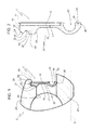
figure 1 shows, in elevation, a longitudinally sectioned view of a rolling-element bearing equipped with the sealing unit for rolling-element bearings according to the invention; and -
figure 2 shows, in enlarged scale, the sealing unit infigure 1 . - With reference to
figure 1 , the numeral 1 indicates, as a whole, a sealing unit for a rolling-element bearing 2. - Rolling-element bearing 2, may be of any known type and comprises an
inner ring 21 that is radially outwardly defined by acylindrical surface 22, and anouter ring 23 that is radially inwardly defined by a respectivecylindrical surface 24, which facessurface 22, and is provided with anannular groove 25. - Groove 25 is made starting from an outer
axial edge 26 ofring 23 which is hook-shaped and is axially delimited toward the interior ofbearing 2 by a front wall 27, which is inclined with respect to an axis A of rotation of unit 1, i.e. ofbearing 2. Between front wall 27 andaxial edge 26,groove 25 is delimited radially inwardly, i.e. towards axis A, by a curved,concave surface 28. - The unit 1 is adapted to be coupled to the
bearing 2 to seal off the annular space between theinner ring 21 and theouter ring 23, and comprises astiffening core 10, and an elastomericannular element 30 preferably constructed with an elastomeric material, such as an elastically deformable rubber material, and directly injection-moulded and vulcanized onstiffening core 10 to which, therefore, it is rigidly secured. - According to what is also shown in
figure 2 ,core 10 is preferably made of metal and gives consistency toannular element 30 so as to allow the snap-fitting of unit 1 withingroove 25, andannular element 30 comprises: - a sealing
lip 31, which extends radially outwards from stiffeningcore 10 towards axis A so as to be in frictional contact withsurface 22 ofinner ring 21; - a
root portion 32, which is positioned radially on the opposite side to sealinglip 31 with respect tocore 10, and which can be snap-fitted intogroove 25; and - an intermediate covering
layer 33, which is arranged betweenroot portion 32 and sealinglip 31 so as to completely cover a single side L1 of stiffeningcore 10 along with saidroot portion 32. Indeed,root portion 32, extending only partly alongstiffening core 10 in a radial direction, covers only a part of side L1. -
Sealing lip 31 is arch-shaped, with the concavity thereof facing axially from opposite side to side L1, and ends with adistal appendix 34 delimited by twosurfaces surface 35 of which is an annular flat surface transversal to axis A, andsurface 36 is a cylindrical surface coaxial toaxis A. Appendix 34 has a greater thickness than an average thickness of theentire lip 31 so as to contact without solution ofcontinuity surface 22 and to define a coefficient of friction of a value which is in any case limited, taking advantage of the elasticity due to the combination between the material ofannular element 30 and between the shape and dimensions oflip 31. -
Root portion 32 has a greater axial thickness than an axial thickness of coveringlayer 33, and is axially delimited by a largefront surface 37, which is inclined with respect to axis A and is adapted to abut in direct contact on front wall 27 ofgroove 25, and from asmall front surface 38, smaller thansurface 37, which is contiguous to largefront surface 37 and, with respect to axis A, has a greater inclination with respect to the inclination offront surface 37. -
Root portion 32 is further defined toward axis A by afurther surface 39, which is positioned on the opposite side ofsurface 38 with respect tosurface 37 and is connected to bothsurface 37 and coveringlayer 33. -
Root portion 32 is further provided with anannular groove 40, which is provided onfront surface 37 in a radially asymmetrical position with respect to largefront surface 37, so as to identify onsurface 37 twofractions fraction 41, adjacent tosurface 38, is smaller with respect tofraction 42 adjacent tosurface 39. Groove 40 has, starting fromfront surface 37, a depth which is smaller than at least one third of an average axial thickness ofroot portion 32 so as to confer to said portion 32 a defined elasticity and capacity for deformation, without, however, leading to the loss of the profile ofportion 32, which is essentially determined bysurface 37. -
Root portion 32 is lastly provided with anengagement projection 50, which projects radially with respect to an outerfree edge 11 ofstiffening core 10, and is defined byfront surface 38 and by a furtherconical surface 51, which is inclined with an inclination opposed tosurface 38 and connectssurface 38 andfree edge 11 to each other. However,projection 50 defines a minor part ofroot portion 32, which is consequently fully backed as a whole by stiffeningcore 10 in the direction of insertion in use of the unit 1 ingroove 25. - The radial extension of stiffening
core 10 measured perpendicularly to axis A, namely the outer diameter offree edge 11,stiffening core 10 being preferably shaped as a flat ring, is slightly larger than the inner diameter ofaxial edge 26. - In use, sealing unit 1 is coupled with bearing 2 so that
engagement projection 50 is snap-fitted intogroove 25 after overcoming a slight resistance due to the radial interference betweenprojection 50 andedge 26. To overcome the slight radial interference betweenfree edge 11 andaxial edge 26 it is possible during insertion merely tilting slightly unit 1. However, according to a preferred embodiment of the invention it is also possible merely renderingcore 10 easily elastically deformable by making it in a very elastic material, like harmonic steel. - Unit 1 will be positioned in its operating position when large
front surface 37 is abutted directly on front wall 27 ofgroove 25 andcore 10 rests internally to edge 26 although only on a small part close toedge 11. In such operating position,core 10 is arranged facing outside bearing 2, and the whole of side L1 is facing axially toward the interior ofbearing 2. - In other words, contrary to what took place in the assembly of the known sealing units described in the introduction, sealing unit 1 of the present invention is arranged in the operating position thereof with
stiffening core 10 to the outside of the bearing, and withannular sealing element 30 placed betweencore 10 and bearing 2. In particular, thanks to this assembly position and to the fact thatfront surface 37 and wall 27 have the same inclination with respect to axis A,surface 37 will lie completely against wall 27 and this coupling will function as a centring element and a guarantee of the operating position of unit 1. - Furthermore, thanks to the presence of
groove 40 in combination with the backing action ofcore 10, the twofractions surface 37 will contribute even more to the maintaining of the assembly position with respect to a possibly completelyfull surface 37. Groove 40 also makeseasier core 10 to be elastically deformed during insertion; likewise, elasticity ofcore 10 and presence ofgroove 40 have a synergistic effect which make easier to keep unit 1 in the correct sealing position. - An immediate advantage of the fact that the operating position of sealing unit 1 is maintained stable as described above, i.e. that
core 10 will not move from a position in whichcore 10 wholly lies in a plane practically orthogonal to axis A like as immediately before insertion of unit 1 ingroove 25, is the fact that neither will sealinglip 31 be affected by any variation of its position on contact withsurface 22 ofinner ring 21. In particular,lip 31 will be able to fully exploit the contact betweensurface 36 andsurface 22 which greatly improves the sealing capacity of unit 1. - Since
core 10 is no longer covered toward the outside ofbearing 2 by elastomericannular element 30, as described above, when unit 1 is used in environments containing substances which are particularly corrosive to metal, it would be advantageous to either makestiffening core 10 of plastic material, or cover the side opposite of side L1, i.e. the side exposed to the outside ofbearing 2, with a film of protective material. - It is understood that the invention is not limited to the embodiment described and illustrated herein, that it is to be considered as an exemplary embodiment of the sealing unit for rolling-element bearings and that it is, on the contrary, susceptible to further modifications relative to the shape and arrangement of parts and construction and assembly details.
Claims (12)
- Sealing unit (1) for rolling-element bearings (2) comprising an inner ring (21) and an outer ring (23), the latter having on the inside at least one groove (25) with a front wall (27) that is inclined with respect to an axis (A) of rotation of the unit, which sealing unit (1) can be coupled to the bearing (2) to seal off the annular space between the inner ring (21) and outer ring (23) and comprises a stiffening core (10) and an elastomeric annular element (30) that is rigidly secured to the stiffening core (10) and that in turn comprises:- a sealing lip (31) extending radially outwards from the stiffening core (10) towards the axis (A) so as to be in frictional contact with the inner ring (21); and- a root portion (32), positioned radially on the opposite side to the sealing lip (31), which can be snap-fitted into the groove (25);the sealing unit (1) being characterized in that, when the sealing unit (1) is coupled to the bearing (2), the root portion (32) is in a position axially internal to the stiffening core (10) and can press directly against the front wall (27) of the groove (25).
- Sealing unit according to Claim 1, characterized in that the root portion (32) is axially delimited by a large front surface (37) that is inclined with respect to the axis (A), the large front surface (37) being in direct contact in use with the front wall (27) of the groove (25).
- Sealing unit according to Claim 2, characterized in that the root portion (32) has an engagement projection (50), projecting radially from an outer free edge (11) of the stiffening core (10), and includes a small front surface (38) contiguous to the large front surface (37) and inclined to a greater degree than said large front surface (37).
- Sealing unit according to Claim 2 or 3, characterized in that the root portion (32) has an annular groove (40) made in the large front surface (37).
- Sealing unit according to Claim 4, characterized in that the annular groove (40) is made in the large front surface (37) in an asymmetrical position with respect to said large front surface (37).
- Sealing unit according to any one of the preceding claims, characterized in that the stiffening core (10) is preferably made of metal, most preferably is made in an harmonic steel, and the root portion (32) covers a single side of the stiffening core (10) and extends only partially along the stiffening core (10) in the radial direction.
- Sealing unit according to Claim 6, characterized in that the elastomeric annular element (30) comprises an intermediate covering layer (33) lying between the root portion (32) and the sealing lip (31) so as to completely cover a single side of the stiffening core (10) along with the root portion (32).
- Sealing unit according to Claim 7, characterized in that the elastomeric annular element (30) is directly injection-moulded and vulcanized on the stiffening core (10), to which it is rigidly secured.
- Sealing unit according to any one of the preceding claims, characterized in that the sealing lip (31) has a free end (34) that is radially defined by a cylindrical surface (36) capable of coming into frictional contact with the inner ring (21).
- Sealing unit according to any one of the preceding claims,characterized in thati)- the radial extension of the stiffening core (10) measured perpendicularly to the axis (A) is such as to be slightly larger than the inner diameter of an axial edge (26) of the groove (25) opposite to the front wall (27); and, in combination,ii)- the root portion (32) has an annular groove (40) facing the side opposite to the stiffening core (10) and toward the outer ring (23) of the bearing (2) in use; the root portion (32) being fully backed as a whole by the stiffening core (10) in the direction of insertion in use of the unit (1) in the groove (25).
- Sealing unit according to any one of the preceding claims, characterized in that in the operating position the core (10) does not move from a position in which the core (10) wholly lies in a plane practically orthogonal to the axis (A) like as immediately before insertion of the unit (1) in the groove (25) of the outer ring (23) of the bearing (2).
- Rolling-element bearing (2) comprising an inner ring (21) and an outer ring (23), the latter having on the inside at least one groove (25) with a front wall (27) that is inclined with respect to an axis (A) of rotation of the unit; and wherein between the front wall (27) and an axial edge (26) opposite thereof of the groove (25), the latter is delimited radially inwardly, i.e. towards the axis (A), by a curved, concave surface 28; the bearing being characterized in comprising a sealing unit (1) as claimed in anyone of the preceding claims.
Applications Claiming Priority (1)
| Application Number | Priority Date | Filing Date | Title |
|---|---|---|---|
| IT001041A ITTO20101041A1 (en) | 2010-12-22 | 2010-12-22 | SEALING UNIT FOR VOLTAGE BEARINGS |
Publications (1)
| Publication Number | Publication Date |
|---|---|
| EP2469111A1 true EP2469111A1 (en) | 2012-06-27 |
Family
ID=43737430
Family Applications (1)
| Application Number | Title | Priority Date | Filing Date |
|---|---|---|---|
| EP20110195454 Withdrawn EP2469111A1 (en) | 2010-12-22 | 2011-12-22 | Sealing unit for rolling-element bearings |
Country Status (4)
| Country | Link |
|---|---|
| US (1) | US9133882B2 (en) |
| EP (1) | EP2469111A1 (en) |
| CN (1) | CN102562815A (en) |
| IT (1) | ITTO20101041A1 (en) |
Families Citing this family (3)
| Publication number | Priority date | Publication date | Assignee | Title |
|---|---|---|---|---|
| JP6227250B2 (en) * | 2013-01-10 | 2017-11-08 | Ntn株式会社 | Bearing seals and rolling bearings with seals |
| EP3269989B1 (en) * | 2015-03-09 | 2021-07-21 | NTN Corporation | Sealed bearing |
| CN106801745A (en) * | 2015-11-25 | 2017-06-06 | 舍弗勒技术股份两合公司 | Bearing and sealing structure for bearing |
Citations (6)
| Publication number | Priority date | Publication date | Assignee | Title |
|---|---|---|---|---|
| US2467049A (en) * | 1946-08-22 | 1949-04-12 | Marlin Rockwell Corp | Seal for rotatable members |
| US2914365A (en) * | 1958-03-18 | 1959-11-24 | Channing Corp | Anti-friction bearings |
| US3226168A (en) * | 1963-01-18 | 1965-12-28 | Fed Bearings Co Inc | Composite seal construction for antifriction bearings |
| DE7833640U1 (en) * | 1979-02-15 | Skf Kugellagerfabriken Gmbh, 8720 Schweinfurt | roller bearing | |
| EP0708263A1 (en) * | 1994-10-18 | 1996-04-24 | SKF Industrial Trading & Development Company, B.V. | Rolling bearing with oil seal |
| FR2926345A1 (en) * | 2008-01-16 | 2009-07-17 | Skf Ab | SEAL JOINT AND BEARING BEARING COMPRISING SUCH A SEAL |
Family Cites Families (35)
| Publication number | Priority date | Publication date | Assignee | Title |
|---|---|---|---|---|
| US2766082A (en) * | 1955-03-03 | 1956-10-09 | Norma Hoffmann Bearings Corp | Bearing seals |
| US2962308A (en) * | 1956-12-27 | 1960-11-29 | Gen Motors Corp | Demountable closure |
| US3032346A (en) * | 1958-08-08 | 1962-05-01 | Gen Motors Corp | Closure for rotatable members |
| US3145996A (en) * | 1962-03-06 | 1964-08-25 | Skf Ind Inc | Seal for bearing |
| GB1138193A (en) * | 1965-02-23 | 1968-12-27 | Angus George Co Ltd | Improvements in and relating to bearing seals |
| US3854734A (en) * | 1969-05-05 | 1974-12-17 | Hoover Ball & Bearing Co | Bearing seal assembly |
| US3700296A (en) * | 1971-01-15 | 1972-10-24 | Ernst Bugmann | Antifriction bearing |
| US3748003A (en) * | 1971-11-01 | 1973-07-24 | Mc Gill Mfg Co Inc | Multiple element bearing seal |
| IT945804B (en) * | 1971-11-26 | 1973-05-10 | Riv Officine Di Villar Perosa | IMPROVEMENTS IN ROLLING BEARINGS NUMBER OF SEALING GASKETS WITH CREEPING LIP |
| US3752544A (en) * | 1972-05-15 | 1973-08-14 | Gen Motors Corp | Sealed bearing with axially undulating seal lip |
| US4054334A (en) * | 1976-03-08 | 1977-10-18 | Schatz Federal Bearings Co. Inc. | Method and apparatus for installing a bearing shield or seal into the annular space of a bearing |
| IT7922779V0 (en) * | 1978-11-11 | 1979-10-08 | Skf Kugellagerfabriken Gmbh | ROLLING BEARING. |
| US4304412A (en) * | 1979-11-02 | 1981-12-08 | Federal-Mogul Corporation | Contoured double-lip bearing seal |
| GB2114682B (en) * | 1982-02-09 | 1985-09-11 | Skf Svenska Kullagerfab Ab | Rolling bearing assemblies fitted with seals |
| IT1169318B (en) * | 1982-06-26 | 1987-05-27 | Skf Kugellagerfabriken Gmbh | SEALING OR GASKET DEVICE |
| IT1211620B (en) * | 1987-12-23 | 1989-11-03 | Riv Officine Di Villar Perosa | WATERPROOF BEARING OF THE PERFECT TYPE AND PROCEDURE FOR ITS REALIZATION |
| US5110222A (en) * | 1990-02-02 | 1992-05-05 | The United States Of America As Represented By The United States Department Of Energy | Positive contact, self retaining bearing seals |
| IT220586Z2 (en) * | 1990-08-28 | 1993-10-04 | Skf Ind Spa | HOLDING COMPLEX |
| JPH0473659U (en) * | 1990-11-07 | 1992-06-29 | ||
| US5163691A (en) * | 1991-09-30 | 1992-11-17 | General Motors Corporation | Stacked seal with improved manufacture |
| EP0636820B1 (en) * | 1993-07-28 | 1998-11-11 | TOYO SEAL INDUSTRIES,Co.,Ltd. | Bearing sealing plate and method of manufacturing thereof |
| JP3157077B2 (en) * | 1994-02-16 | 2001-04-16 | 内山工業株式会社 | Bearing seal |
| IT239862Y1 (en) * | 1996-12-03 | 2001-03-13 | R F T S P A | SEALING COMPLEX FOR A ROTATING SHAFT, IN PARTICULAR OF A WATER PUMP OF AN AUTOMOTIVE ENGINE. |
| SE9800517D0 (en) * | 1998-02-23 | 1998-02-23 | Skf Sverige Ab | Bearing seals |
| SE9804613L (en) * | 1998-12-30 | 2000-07-01 | Skf Sverige Ab | sealing device |
| JP2003074491A (en) * | 2001-09-04 | 2003-03-12 | Nsk Ltd | Water pump seal device, water pump rotation support device, and water pump |
| JP2003113947A (en) * | 2001-10-01 | 2003-04-18 | Ntn Corp | Sealing device, rolling bearing and clutch device provided with the same |
| EP1493935B1 (en) * | 2003-06-30 | 2007-08-15 | JTEKT Corporation | Rolling bearing |
| JP4603304B2 (en) * | 2004-07-20 | 2010-12-22 | Ntn株式会社 | Sealed rolling bearing |
| DE112005003283T5 (en) * | 2004-12-28 | 2007-11-15 | Ntn Corp. | roller bearing |
| ITTO20050088A1 (en) * | 2005-02-15 | 2006-08-16 | Rft Spa | SEALING DEVICE FOR BEARINGS WITH INTEGRATED ENCODER. |
| DE502005002045D1 (en) * | 2005-06-25 | 2008-01-03 | Zahnradfabrik Friedrichshafen | Rolling bearing with a sealing element |
| JP4535018B2 (en) * | 2006-03-29 | 2010-09-01 | 株式会社ジェイテクト | Roller bearing device for pinion shaft support |
| JP5170369B2 (en) * | 2007-04-10 | 2013-03-27 | Nok株式会社 | Sealing device |
| CN101699090A (en) * | 2009-11-12 | 2010-04-28 | 常熟长城轴承有限公司 | Sealing structure for bearing |
-
2010
- 2010-12-22 IT IT001041A patent/ITTO20101041A1/en unknown
-
2011
- 2011-12-12 US US13/316,661 patent/US9133882B2/en not_active Expired - Fee Related
- 2011-12-21 CN CN2011104332835A patent/CN102562815A/en active Pending
- 2011-12-22 EP EP20110195454 patent/EP2469111A1/en not_active Withdrawn
Patent Citations (6)
| Publication number | Priority date | Publication date | Assignee | Title |
|---|---|---|---|---|
| DE7833640U1 (en) * | 1979-02-15 | Skf Kugellagerfabriken Gmbh, 8720 Schweinfurt | roller bearing | |
| US2467049A (en) * | 1946-08-22 | 1949-04-12 | Marlin Rockwell Corp | Seal for rotatable members |
| US2914365A (en) * | 1958-03-18 | 1959-11-24 | Channing Corp | Anti-friction bearings |
| US3226168A (en) * | 1963-01-18 | 1965-12-28 | Fed Bearings Co Inc | Composite seal construction for antifriction bearings |
| EP0708263A1 (en) * | 1994-10-18 | 1996-04-24 | SKF Industrial Trading & Development Company, B.V. | Rolling bearing with oil seal |
| FR2926345A1 (en) * | 2008-01-16 | 2009-07-17 | Skf Ab | SEAL JOINT AND BEARING BEARING COMPRISING SUCH A SEAL |
Also Published As
| Publication number | Publication date |
|---|---|
| ITTO20101041A1 (en) | 2012-06-23 |
| US9133882B2 (en) | 2015-09-15 |
| US20120161402A1 (en) | 2012-06-28 |
| CN102562815A (en) | 2012-07-11 |
Similar Documents
| Publication | Publication Date | Title |
|---|---|---|
| US8517389B2 (en) | Fixing arrangement for a rubber seal for sealing a rolling bearing | |
| US8590903B2 (en) | Lip seal with inversion prevention feature | |
| CN103201532B (en) | Around sealing device | |
| US10480658B2 (en) | Mechanical seal arrangement having a bellows element | |
| EP1696154B1 (en) | Dynamic seal | |
| EP2615337B1 (en) | Shaft sealing device | |
| EP2128501B1 (en) | Hermetic sealing device | |
| US7017913B2 (en) | Axial shaft seal | |
| CN112610609B (en) | Dynamically acting seals especially for rolling bearings | |
| JP2008281192A (en) | Seal ring | |
| WO2014030742A1 (en) | Sealing device | |
| JP2018035855A (en) | Sealing device | |
| US9133882B2 (en) | Sealing unit for rolling-element bearings | |
| EP3470711A1 (en) | Seal assembly | |
| CN101517286A (en) | Sealing device | |
| US7854432B2 (en) | Dynamic seal | |
| CN106122263B (en) | Bearings including elastomeric bearing flanges | |
| JP2011158031A (en) | Needle roller bearing | |
| JP2010025255A (en) | Boot for constant velocity joint | |
| CN106122284B (en) | Bearing comprising a sealing flange | |
| WO2010069386A1 (en) | A sealing device for bearing units | |
| JP2008286320A (en) | Sealing device | |
| JP2008169917A (en) | Rolling bearing |
Legal Events
| Date | Code | Title | Description |
|---|---|---|---|
| AK | Designated contracting states |
Kind code of ref document: A1 Designated state(s): AL AT BE BG CH CY CZ DE DK EE ES FI FR GB GR HR HU IE IS IT LI LT LU LV MC MK MT NL NO PL PT RO RS SE SI SK SM TR |
|
| AX | Request for extension of the european patent |
Extension state: BA ME |
|
| PUAI | Public reference made under article 153(3) epc to a published international application that has entered the european phase |
Free format text: ORIGINAL CODE: 0009012 |
|
| 17P | Request for examination filed |
Effective date: 20121227 |
|
| 17Q | First examination report despatched |
Effective date: 20150902 |
|
| STAA | Information on the status of an ep patent application or granted ep patent |
Free format text: STATUS: EXAMINATION IS IN PROGRESS |
|
| STAA | Information on the status of an ep patent application or granted ep patent |
Free format text: STATUS: THE APPLICATION IS DEEMED TO BE WITHDRAWN |
|
| 18D | Application deemed to be withdrawn |
Effective date: 20170701 |