EP2469045A2 - Turbine airfoil components containing ceramic-based materials and processes therefor - Google Patents
Turbine airfoil components containing ceramic-based materials and processes therefor Download PDFInfo
- Publication number
- EP2469045A2 EP2469045A2 EP20110193396 EP11193396A EP2469045A2 EP 2469045 A2 EP2469045 A2 EP 2469045A2 EP 20110193396 EP20110193396 EP 20110193396 EP 11193396 A EP11193396 A EP 11193396A EP 2469045 A2 EP2469045 A2 EP 2469045A2
- Authority
- EP
- European Patent Office
- Prior art keywords
- subcomponent
- nub
- turbine
- ceramic
- airfoil
- Prior art date
- Legal status (The legal status is an assumption and is not a legal conclusion. Google has not performed a legal analysis and makes no representation as to the accuracy of the status listed.)
- Granted
Links
Images


Classifications
-
- F—MECHANICAL ENGINEERING; LIGHTING; HEATING; WEAPONS; BLASTING
- F01—MACHINES OR ENGINES IN GENERAL; ENGINE PLANTS IN GENERAL; STEAM ENGINES
- F01D—NON-POSITIVE DISPLACEMENT MACHINES OR ENGINES, e.g. STEAM TURBINES
- F01D5/00—Blades; Blade-carrying members; Heating, heat-insulating, cooling or antivibration means on the blades or the members
- F01D5/12—Blades
- F01D5/28—Selecting particular materials; Particular measures relating thereto; Measures against erosion or corrosion
- F01D5/284—Selection of ceramic materials
-
- F—MECHANICAL ENGINEERING; LIGHTING; HEATING; WEAPONS; BLASTING
- F01—MACHINES OR ENGINES IN GENERAL; ENGINE PLANTS IN GENERAL; STEAM ENGINES
- F01D—NON-POSITIVE DISPLACEMENT MACHINES OR ENGINES, e.g. STEAM TURBINES
- F01D5/00—Blades; Blade-carrying members; Heating, heat-insulating, cooling or antivibration means on the blades or the members
- F01D5/12—Blades
- F01D5/14—Form or construction
- F01D5/147—Construction, i.e. structural features, e.g. of weight-saving hollow blades
-
- F—MECHANICAL ENGINEERING; LIGHTING; HEATING; WEAPONS; BLASTING
- F01—MACHINES OR ENGINES IN GENERAL; ENGINE PLANTS IN GENERAL; STEAM ENGINES
- F01D—NON-POSITIVE DISPLACEMENT MACHINES OR ENGINES, e.g. STEAM TURBINES
- F01D5/00—Blades; Blade-carrying members; Heating, heat-insulating, cooling or antivibration means on the blades or the members
- F01D5/30—Fixing blades to rotors; Blade roots ; Blade spacers
- F01D5/3084—Fixing blades to rotors; Blade roots ; Blade spacers the blades being made of ceramics
-
- F—MECHANICAL ENGINEERING; LIGHTING; HEATING; WEAPONS; BLASTING
- F05—INDEXING SCHEMES RELATING TO ENGINES OR PUMPS IN VARIOUS SUBCLASSES OF CLASSES F01-F04
- F05D—INDEXING SCHEME FOR ASPECTS RELATING TO NON-POSITIVE-DISPLACEMENT MACHINES OR ENGINES, GAS-TURBINES OR JET-PROPULSION PLANTS
- F05D2300/00—Materials; Properties thereof
- F05D2300/60—Properties or characteristics given to material by treatment or manufacturing
- F05D2300/603—Composites; e.g. fibre-reinforced
- F05D2300/6033—Ceramic matrix composites [CMC]
-
- Y—GENERAL TAGGING OF NEW TECHNOLOGICAL DEVELOPMENTS; GENERAL TAGGING OF CROSS-SECTIONAL TECHNOLOGIES SPANNING OVER SEVERAL SECTIONS OF THE IPC; TECHNICAL SUBJECTS COVERED BY FORMER USPC CROSS-REFERENCE ART COLLECTIONS [XRACs] AND DIGESTS
- Y02—TECHNOLOGIES OR APPLICATIONS FOR MITIGATION OR ADAPTATION AGAINST CLIMATE CHANGE
- Y02T—CLIMATE CHANGE MITIGATION TECHNOLOGIES RELATED TO TRANSPORTATION
- Y02T50/00—Aeronautics or air transport
- Y02T50/60—Efficient propulsion technologies, e.g. for aircraft
Definitions
- the present invention generally relates to ceramic-based articles and processes for their production. More particularly, this invention is directed to ceramic-based articles produced to include metallic regions that define detailed features, for example, dovetails, shanks, platform features and tip shrouds of gas turbine airfoil components.
- Ceramic materials are a notable example because their high temperature capabilities can significantly reduce cooling air requirements.
- ceramic-based materials encompass homogeneous ceramic materials as well as ceramic matrix composite (CMC) materials.
- CMC materials generally comprise a ceramic fiber reinforcement material embedded in a ceramic matrix material.
- the reinforcement material may be discontinuous short fibers dispersed in the matrix material or continuous fibers or fiber bundles oriented within the matrix material.
- the reinforcement material serves as the load-bearing constituent of the CMC in the event of a matrix crack.
- the ceramic matrix protects the reinforcement material, maintains the orientation of its fibers, and serves to dissipate loads to the reinforcement material.
- Silicon-based composites such as silicon carbide (SiC) as the matrix and/or reinforcement material, are of particular interest to high-temperature applications, for example, high-temperature components of gas turbines including aircraft gas turbine engines and land-based gas turbine engines used in the power-generating industry.
- Continuous fiber reinforced ceramic composites are a type of CMC that offers light weight, high strength, and high stiffness for a variety of high temperature load-bearing applications, including shrouds, combustor liners, vanes (nozzles), blades
- CFCC CFCC
- HiPerComp® CFCC
- SiC fibers have also been used as a reinforcement material for a variety of other ceramic matrix materials, including titanium carbide (TiC), silicon nitride (Si 3 N 4 ), and alumina (Al 2 O 3 ).
- CMC materials and particularly SiC/Si-SiC (fiber/matrix) CFCC materials and processes are disclosed in U.S. Patent Nos. 5,015,540 , 5,330,854 , 5,336,350 , 5,628,938 , 6,024,898 , 6,258,737 , 6,403,158 , and 6,503,441 , and U.S. Patent Application Publication No. 2004/0067316 .
- prepreg melt-infiltration MI
- CFCC fused metal carbide
- binders typically carbon or a carbon source.
- the prepreg must undergo processing (including firing) to convert the precursor to the desired ceramic.
- Prepregs for CFCC materials frequently comprise a two-dimensional fiber array comprising a single layer of unidirectionally-aligned tows impregnated with a matrix precursor to create a generally two-dimensional laminate.
- a low pressure turbine (LPT) blade 10 of a gas turbine engine is represented in FIG. 1 .
- the blade 10 is an example of a component that can be produced from a ceramic-based material, including CMC materials.
- the blade 10 is generally represented as being of a known type and adapted for mounting to a disk or rotor (not shown) within the turbine section of an aircraft gas turbine engine.
- the blade 10 is represented as including a dovetail 12 for anchoring the blade 10 to a turbine disk by interlocking with a complementary dovetail slot formed in the circumference of the disk.
- the interlocking features comprise protrusions referred to as tangs 14 that engage recesses defined by the dovetail slot.
- the blade 10 is further shown as having a platform 16 that separates an airfoil 18 from a shank 20 on which the dovetail 12 is defined.
- the blade 10 may be further equipped with a blade tip shroud (not shown) which, in combination with tip shrouds of adjacent blades within the same stage, defines a band around the blades that is capable of reducing blade vibrations and improving airflow characteristics.
- blade tip shrouds are further capable of increasing the efficiency of the turbine by reducing combustion gas leakage between the blade tips and a shroud surrounding the blade tips.
- the platform 16 and blade tip shroud are further critical regions of a turbine blade in that they create the inner and outer flowpath surfaces for the hot gas path within the turbine section.
- the platform 16 creates a seal to prevent mixing of the hot combustion gases with lower temperature gases to which the shank 20, its dovetail 12 and the turbine disk are exposed, and the blade tip shroud is subjected to creep due to high strain loads and wear interactions between its seal tooth (if present) and the shroud surrounding the blade tips.
- the dovetail 12 is also a critical region in that it is subjected to wear and high loads resulting from its engagement with a dovetail slot and the high centrifugal loading generated by the blade 10.
- the platform 16, dovetail 12 and its tangs 14 have interface/support functions that can require structural interface capabilities that can be difficult to achieve with CMC materials.
- the low strain-to-failure capabilities of typical CMC materials and the possibility of undesirable wear interactions between tip shroud seal teeth and conventional shrouding materials pose additional challenges to implementing CMC materials in shrouded blade designs.
- the present invention provides hybrid turbine airfoil components containing a ceramic material, in which detailed features of the components are formed of materials other than ceramic materials, yet result in a robust mechanical attachment of the ceramic and non-ceramic portions of the components.
- a turbine airfoil component includes a first subcomponent formed of a ceramic-based material and a second subcomponent formed of a metallic material.
- the first subcomponent comprises an airfoil portion and a nub
- the second subcomponent is separately formed and attached to the first subcomponent by casting the metallic material around the nub of the first subcomponent.
- the second subcomponent includes a platform portion between the airfoil portion and the nub of the first subcomponent and a dovetail portion on the nub of the first subcomponent.
- Each of the platform and dovetail portions has at least one off-axis geometric feature that results in the second subcomponent having a more complex geometry than the first subcomponent.
- a technical effect of this invention is the ability to produce certain portions of a turbine airfoil component from a ceramic-based material, while producing other portions of the component having intricate geometric details from materials that do not require the temperature capability of ceramic-based materials.
- the invention is particularly beneficial for applications in which the intricate geometric details formed of the non-ceramic material are interface/supporting features that require structural interface capabilities, and as a result of being fabricated from a non-ceramic material are not nearly as labor intensive or require the level of skilled labor that would be required if the entire component were fabricated from a ceramic-based material.
- the present invention will be described in terms of processes for producing components containing ceramic-based materials, including homogeneous ceramic materials and CMC materials that may contain discontinuous and/or continuous fiber reinforcement materials. While various applications are foreseeable and possible, applications of particular interest include are high temperature applications, for example, components of gas turbines, including land-based and aircraft gas turbine engines. Furthermore, specific reference will be made to airfoil components, including turbine blades and vanes for use within the turbine sections of a gas turbine engine. While the invention is applicable to a wide variety of ceramic-based materials, ceramic-based materials of particular interest to the invention are believed to be CMC materials containing silicon, such as CMC's containing silicon carbide as the reinforcement and/or matrix material, for example, continuous silicon carbide fibers in a matrix of silicon carbide. However, other ceramic-based materials are also within the scope of the invention.
- FIGS. 2 and 3 represent a low pressure turbine (LPT) blade 30 of a type used in an aircraft gas turbine engine. Similar to the prior art blade 10 of FIG. 1 , the blade 30 represented in FIGS. 2 and 3 is adapted for mounting to a disk or rotor (not shown) within the turbine section of a gas turbine engine. For this reason, the blade 30 is represented as including a dovetail portion 32 for anchoring the blade 30 to a turbine disk. The dovetail portion 32 is configured to interlock with a complementary dovetail slot formed in the circumference of the disk. As represented in FIGS. 2 and 3 , the interlocking features comprise oppositely-disposed tangs 34 that protrude from the dovetail portion 32 for engagement with recesses defined by the disk dovetail slot.
- LPT low pressure turbine
- the blade 30 is further shown as having a platform portion 36 that separates an airfoil portion 38 from a shank portion 40 on which the dovetail portion 32 is defined.
- the blade 30 may comprise additional features, for example, angelwings 42 on its shank portion 40 and a shroud at its blade tip (for example, as represented in FIGS. 16 and 17 ).
- the airfoil portion 38 and platform portion 36 are directly exposed to hot combustion gases during operation of the engine, and the platform portion 36 is a critical region of the blade 30 in that it creates the inner flowpath surface of the hot gas path for the hot combustion gases, and creates a seal to prevent mixing of the combustion gases with lower temperature gases internal to the rotating system and to which the shank portion 40, its dovetail portion 32 and the turbine disk are exposed.
- the dovetail portion 32 is subjected to wear and high loads as a result of its engagement with the disk dovetail slot and the high centripetal loading generated by the blade 30.
- the airfoil portion 38 of the blade 30 is an excellent candidate for being produced from a ceramic-based material, and especially a CMC material, because it is directly exposed to the hot combustion gases and has a generally linear geometry.
- the platform portion 36, dovetail portion 32 and its tangs 34 have more complex geometries than the airfoil portion 38, in the sense that the airfoil portion 38 has a generally linear geometry along its dominant axis, whereas the dovetail and platform portions 32 and 36 define geometric features oriented transverse to each of their dominant axes.
- the present invention provides a process for taking advantage of the high-temperature capabilities of CMC materials, while avoiding the difficulties of producing complicated geometries from CMC materials.
- the present invention involves producing the airfoil portion 38 and a nub 48 of the shank portion 40 as a unitary piece from a CMC material, and producing one or both of the platform portion 36 and dovetail portion 32 from materials other than the CMC material used to produce the unitary airfoil portion 38 and shank nub 48.
- shank nub refers to a limited portion, preferably an interior region, of the entire shank portion 40, which further includes the dovetail portion 32 and its tangs 34.
- the shank nub 48 is entirely encased in the material used to form the platform portion 36 and dovetail portion 32.
- shank nub 48 can be referred to as being "defeatured,” in that the detailed dovetail features conventionally required for a shank (such as the dovetail 12 and tangs 14 of the shank 20 of FIG. 1 ) can be completely omitted from the shank nub 48 shown in FIGS. 2 and 3 .
- the unitary airfoil portion 38 and shank nub 48 can be produced by known ceramic processes.
- the unitary airfoil portion 38 and shank nub 48 can be CMC materials fabricated from prepregs.
- Nonlimiting examples include the processes disclosed in U.S. Patent Nos. 5,015,540 , 5,330,854 , 5,336,350 , 5,628,938 , 6,024,898 , 6,258,737 , 6,403,158 , and 6,503,441 , and U.S. Patent Application Publication No. 2004/0067316 .
- the unitary airfoil portion 38 and shank nub 48 can be fabricated by the previously-described prepreg melt-infiltration (MI) process, wherein multiple prepregs are formed to contain the desired reinforcement material and a precursor of the CMC matrix material, as well as one or more binders and, depending on the particular desired CMC material, possibly carbon or a carbon source.
- MI prepreg melt-infiltration
- the prepregs undergo lay-up, are debulked and cured while subjected to elevated pressures and temperatures, and subjected to any other suitable processing steps to form a laminate preform. Thereafter, the laminate preform may be heated in a vacuum or an inert atmosphere to decompose the binders and produce a porous preform that is then melt infiltrated.
- the CMC material contains a silicon carbide reinforcement material in a ceramic matrix of silicon carbide (a SiC/SiC CMC material)
- molten silicon is typically used to infiltrate into the porosity, react with a carbon constituent (carbon, carbon source, or carbon char) within the matrix to form silicon carbide, and fill the porosity.
- carbon constituent carbon, carbon source, or carbon char
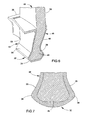
- FIG. 4 represents an example of a unitary CMC subcomponent 44 that comprises the airfoil portion 38 and shank nub 48, is entirely formed of a CMC material, and can be produced by a CMC process such as that described above.
- the shank nub 48 comprises an enlarged knob or base 49 that is wider in cross-section than the region of the nub 48 adjacent the root of the airfoil portion 38. This uncomplicated feature can also be formed with the CMC process, and is desirable for assisting in the retention of the dovetail portion 32 of the blade 30.
- those regions of blades (and other turbine components) that are not directly exposed to the hot combustion gases, including the dovetail, platform and shank portions 32, 36 and 40 of the blade 30, may utilize materials with lower temperature capabilities, for example, nickel-, cobalt- or iron-based alloys currently available and used in turbomachinery.
- materials with lower temperature capabilities for example, nickel-, cobalt- or iron-based alloys currently available and used in turbomachinery.
- superalloys as IN (Inconel) 718, René N5 ( U.S. Patent No. 6,074,602 ), René N6 ( U.S. Patent No. 5,455,120 ), GTD-444®, René 77 ( U.S. Patent No.
- FIG. 5 represents a unitary subcomponent 46 that, in combination with the CMC subcomponent 44 of FIG. 4 , preferably yields the complete blade 30 of FIGS. 2 and 3 .
- the subcomponent 46 is formed of one or more of the aforementioned metal alloy materials.
- the subcomponent 46 of FIG. 5 is not configured to be prefabricated and then assembled with the CMC subcomponent 44 by inserting the shank nub 48 into a complimentary cavity 52 defined in the subcomponent 46, though such an approach is not outside the scope of the invention.
- one approach that has been developed during investigations leading to this invention involves forming the subcomponent 46 by casting metallic material around the shank nub 48 of the CMC subcomponent 44. This approach is practical in view of typical CMC materials having higher processing temperatures than the casting temperatures of a wide range of metallic materials suitable for forming the metallic subcomponent 46, which therefore allows the merging of established metallic casting processes with the CMC subcomponent 44.
- a metallic material can be cast around the shank nub 48 of the simplified, de-featured CMC subcomponent 44, to produce the entire unitary metallic subcomponent 46, which in effect is an overlaying metal casing that defines the dovetail portion 32 and its tangs 34, as well as what will be referred to as a shank casing 50 that encases the portion of the shank nub 48 above the dovetail portion 32 of the subcomponent 46.
- the unitary metallic subcomponent 46 is further represented as defining the platform portion 36, such that the shank casing 50 is disposed between the dovetail and platform portions 32 and 36. Additional features can also be defined by the metallic subcomponent 46, including the angelwings 42 extending from the shank casing 50.
- CTE coefficient of thermal expansion
- a suitable compression fit is believed to be achievable with a metallic material such as the aforementioned nickel-based superalloy René 80H, which has a CTE of about 14 ppm/°C, in comparison to a CTE of about 4 ppm/°C for SiC-SiC CMC materials.
- This CTE differential is capable of yielding a strain of about 1% when cooled to room temperature from a casting temperature of about 2200°F (about 1200°C), resulting in a room temperature stress state in which the CMC shank nub 48 is in compression and the metallic subcomponent 46 surrounding the nub 48 is in tension.
- the shrink-fit resulting from the casting process is capable of providing a robust mechanical attachment.
- FIG. 6 is a perspective view showing a cross-section of the blade 30 in the region of the interface between its subcomponents 44 and 46, evidencing in more detail the manner in which the metallic subcomponent 46 can be used to completely encase the shank nub 48, including its base 49.
- FIG. 7 is a detailed end view of the dovetail portion 32 represented in FIG. 6 , evidencing how the metallic subcomponent 46 fully encases the base 49 of the shank nub 48, and in doing so defines pressure faces 35 that will engage surfaces of the disk dovetail slot in which the blade 30 is to be installed.
- FIG. 8 is a similar end view showing a blade dovetail portion 32A installed in a disk dovetail slot 54 of a turbine rotor disk 56.
- the dovetail portion 32A is similar to the dovetail portion 32 of FIGS. 2-7 , but differs in that the metallic material has not been cast to cover the lower surface of the shank nub base 49. Instead, the subcomponent 46 covers the shank nub base 49 to the extent necessary to define the pressure faces 35.
- FIG. 9 is a view similar to the view depicted in FIG. 7 , but depicts a dovetail portion 32B having multiple sets of tangs 34B and 34C instead of the single set of tangs 34 depicted in FIGS. 2-8 . Furthermore, the metallic material has not been cast to cover any part of the shank nub base 49.
- the subcomponent 46 covers surfaces of the shank nub 48 above its base 49 so that the metallic subcomponent 46 is cast to define the tangs 34B and the pressure faces 35 of the dovetail portion 32 in their entirety.
- the base 48 in effect, defines the lower set of tangs 34C in their entirety, which are subjected to lower loads (if any) due to the reliance of the pressure faces 35 defined by the upper set of tangs 34C.
- FIG. 10 is similar to FIG. 9 , but depicts metallic material as having been cast to cover the entire shank nub base 49, with the result that the metallic subcomponent 46 defines the dovetail portion 32B and both sets of tangs 34B and 34C in their entirety.
- FIGS. 11 and 12 are isolated perspective views of the shank nub 48 of FIG. 3 modified to have slots 60 and holes 62, respectively, for promoting the attachment of the CMC subcomponent 44 to the metallic subcomponent 46.
- the slots 60 are defined as limited recesses in the shank nub base 49, whereas the holes 62 preferably pass entirely through the shank nub 48 above its base 49.
- metallic material enters the slots 60 and/or holes 62 during the casting process, such that solidification of the casting material creates complementary interlocking metallic features (not shown) within the slots 60 and/or holes 62.
- the casting material within the holes 62 is also capable of interconnecting those portions of the shank casing 50 separated by the shank nub 48.
- FIGS. 11 and 12 show the slots 60 and holes 62 as alternative configurations, combinations of slots 60 and holes 62 are also within the scope of the invention.
- other negative surface features could be defined in the shank nub 48 and/or its base 49 to achieve a similar effect.
- positive surface features (protuberances) 63 can also be defined in the shank nub 48 and/or its base 49 and, alone or in combination with recesses (such as slots 60 and/or holes 62) employed to achieve a retention effect similar to negative surface features.
- FIG. 14 schematically represents a co-casting process for simultaneously forming and attaching the metallic subcomponent 46 and its unitary dovetail, platform and shank portions 32, 36 and 40 on the CMC subcomponent 44 and its unitary airfoil portion 38 and shank nub 48.
- the process may be performed within a mold 64 to produce a casting 66 whose shape approximates the final geometry desired for the dovetail, platform and shank portions 32, 36 and 40, and thereby minimize the amount of post-cast machining required of the casting 66 to produce the subcomponent 46.
- the mold 64 may be any suitable design, for example, a ceramic shell. Following solidification of the metallic material, the mold 64 can be removed to retrieve the co-cast subcomponent 46 that has been cast in-situ onto the shank nub 48 of the CMC subcomponent 44. Notably, this casting technique is preferably performed to avoid the high temperatures and long time exposures normally required in conventional investment casting processes, which could result in undesirable chemical reactions between the CMC material of the subcomponent 44 and the molten metal material (for example, the formation of silicides), as well as with the mold 64. The process of ramping the shank nub 48 of the CMC component 44 into the molten metallic material within the mold 64 enables the contact time and temperature to be kept to a minimum to prevent undesirable reactions.
- spin casting techniques are similar to conventional investment casting processes in the fact that a mold is created by coating a wax replica of the part in ceramic, and then removing the wax to yield a female form the part ("mold"), which is then filled with molten metal that solidifies to form the final part.
- Spin casting techniques depart from conventional casting methods in that the latter relies on gravitational force to act on a molten metal to fill the mold, whereas the mold in a spin casting process is rotated to induce centrifugal forces that act on the molten metal. This additional force is beneficial to certain casting geometries and/or materials to ensure a complete fill of the mold with acceptable microstructure and lack of internal defects.
- Spin casting also differs from centrifugal casting processes, in which a molten metal is poured from a crucible into a central pour cup that is aligned with the rotational axis of a rotating mold.
- the molten metal initially has zero centrifugal force acting upon it, and takes a finite amount of time until it flows away from the center of rotation and slowly picks up centrifugal force.
- the charge unmelted raw material
- the charge is melted at a distance way from the center of rotation, such that when the charge is melted and rotation starts, the molten metal is immediately acted upon by centrifugal force, resulting in a more rapid fill of the mold than either conventional or centrifugal casting processes.
- the subcomponent 46 depicted in FIG. 5 could be prefabricated and then assembled with the CMC subcomponent 44.
- the subcomponent 46 can be fabricated as two or more pieces that can be assembled around the shank nub 48 and then welded or brazed to each other to form the complete subcomponent 46.
- this approach would require precision machining to control interface contact stresses between the CMC and metallic subcomponents 44 and 46 and achieve an effective level of compression and encapsulation of the CMC shank nub 48 comparable to that possible with casting techniques.
- an advantage to this approach is the ability to use alloys with melting temperatures that would be otherwise incompatible with the CMC material of the subcomponent 44, for example, due to posing an excessive risk of reactivity or exceeding the temperature capability of the CMC material.
- a prefabrication technique it may be possible to fill gaps between the CMC subcomponent 44 and the individual pieces of the metallic subcomponent 46 during assembly of the pieces.
- gaps could be filled during the assembly process with a powdered braze filler material, which is then sufficiently melted during brazing to join the pieces of the subcomponent 46 together.
- Brazing temperatures for example, in a range of about 2200 to about 2300°F (about 1200 to about 1260°C), would be compatible with most CMC materials currently being contemplated for the invention.
- FIG. 15 schematically represents a portion of an interface region between the CMC and metallic subcomponents 44 and 46 of the blade of FIGS. 2 and 3 , and represents a coating system 70 at the interface for inhibiting chemical interactions therebetween.
- the coating system 70 can be produced to have any number of coating layers formed of a variety of different materials, and can be deposited with the use of a variety of processes, including slurry coating, air plasma spraying (APS), and so forth.
- the coating system 70 is represented as comprising two distinct layers 72 and 74, though the coating system 70 could be formed by a single layer or more than two layers, as an example, five layers.
- the layer 72 directly contacting the CMC subcomponent 44 may be formed by, for example, a material that is particularly compatible with the material of the CMC subcomponent 44, for example, a glass and/or liquid-phase forming material. Examples of potential glass materials for the layer 72 include materials described for a reaction barrier coating disclosed in U.S. Patent Application Serial No.
- the layer 74 directly contacting the metallic subcomponent 46 may be formed by, for example, a material that provides a suitable transition between the layer 72 and the metallic subcomponent 46 in terms of chemical and physical compatibility.
- the layer 74 may have a graded composition in which its composition immediately adjacent the layer 72 is the same as or otherwise compatible with the glass and/or liquid-phase forming material of the layer 72, while its composition immediately adjacent the subcomponent 46 is the same as or otherwise compatible with the metallic material used to form the subcomponent 46.
- the layer 74 or at least its composition immediately adjacent the subcomponent 46 may contain or consist of a ductile metal foam material that is chemically compatible with the metallic material of the subcomponent 46 and provides thermal expansion compliance between the CMC and metallic subcomponents 44 and 46.
- Suitable materials for the foam material are believed to include high-temperature oxidation-resistant alloys such as iron-, cobalt- and nickel-based alloys, notable but nonlimiting examples of which include FeCrAIY alloys of types known in the art.
- the layers 72 and 74 preferably confer a degree of compliance to the coating system 70, enabling the coating system 70 to serve as a compliant interface that accommodates shrinkage of the metal subcomponent 46 around the CMC subcomponent 44 during solidification.
- thicknesses of about 0.005 to about 0.040 inch (about 0.1 to 1 millimeter) are believed to be suitable for the coating system 70, though lesser and greater thicknesses are also foreseeable.
- FIGS. 16 and 17 represent an LPT turbine blade 80 that is shrouded, whereas the blade 30 in FIGS. 2 through 15 is unshrouded.
- the blade 80 comprises a CMC subcomponent 82 that defines an airfoil portion 84.
- the blade further comprises a dovetail portion 86 and a platform portion 88.
- the CMC subcomponent 82 may be formed to have a shank nub (not shown) surrounded by a metallic subcomponent that defines the dovetail and platform portions 86 and 88, generally in a manner similar to that described for the blade 30. Contrary to the blade 30, the blade 80 represented in FIGS.
- the 16 and 17 comprises a metallic subcomponent 90 that defines a shroud portion 92 at the tip of the CMC airfoil portion 84, which effectively defines a nub 94 for attachment of the shroud portion 92 to the airfoil portion 84.
- the metallic subcomponent 90 is further represented as defining an integrated seal tooth 96.
- the metallic subcomponent 90 can be formed in the same manner as that described for the metallic subcomponent 46 of the blade 30.
- the blade tip nub 94 can have an shape similar to the shank nub 48 depicted in FIGS. 4 and 6-13 , for the blade 30.
- the blade tip nub 94 is wider in cross-section than the immediately adjacent region of the airfoil portion 84, and serves to assist in the retention of the metallic subcomponent 90 and its shroud portion 92 at the tip of the CMC airfoil portion 84.
- the blade tip nub 94 can further incorporate positive and negative surface features that, during the co-casting process to produce the metallic subcomponent 90 and its shroud portion 92, result in the creation of integral complementary interlocking metallic features. As represented in FIGS.
- the numb 94 can have through-holes 98A ( FIGS. 19 and 20 ) and/or slots 98B ( FIG. 21 ) of various sizes and shapes.
- metallic material enters the holes 98A during the casting process, such that solidification of the casting material creates complementary interlocking metallic crossbars that extend entirely through the holes 98A to interconnect portions of the shroud portion 92 separated by the nub 94.
- the slots 98B the casting material within the slots 98B creates complementary interlocking metallic ribs that extend entirely through the slots 98B to interconnect portions of the shroud portion 92 separated by the nub 94.
- FIGS. 19 through 21 represent only negative surface features, positive surface features (protuberances) could be defined in the nub 94 as an alternative or in addition to the holes 98A and/or slots 98B to achieve a retention effect similar to negative surface features.
- FIGS. 22 and 23 represent a gas turbine vane segment 100 as another suitable application for the present invention.
- the vane segment 100 is represented as having two airfoil portions (vanes) 102 between a pair of inner and outer platforms (bands) 104, though a single airfoil portion 102 or more than two airfoil portions 102 could be present.
- the vane segment 100 is one of a number of vane segments that are assembled together to form an annular-shaped vane assembly of a turbine engine.
- the airfoil portions 102 are excellent candidates for being produced from ceramic-based materials because they are directly exposed to hot combustion gases and have generally linear geometries.
- each vane airfoil portion 102 can be produced as a unitary piece from a ceramic-based material, for example, a CMC material, and one or both of the platforms 104 can be produced from materials other than a ceramic material.
- each airfoil portion 102 comprises a pair of oppositely-disposed nubs 106.
- Each nub 106 is effectively a dovetail feature that defines an oppositely-disposed pair of tangs 108.
- the nubs 106 are entirely encased in the material used to form the platforms 104 so that the nubs 106 and their tangs 108 are received within pockets 110 that were defined in the platforms 104 during a metal casting process used to form the platforms 104.
- each nub 106 and its tangs 108 define a region on the airfoil portion 102 that is wider in cross-section than the immediately adjacent region of the airfoil portion 102, and as such the nubs 106 are configured to serve as retention features for retaining the inner and outer platforms 104 on the airfoil portion 102, as well as retain the nubs 106 within the pockets 110 of the platforms 104.
- Other aspects regarding the production of the vane assembly 100 can be appreciated from the discussions above regarding the turbine blades 30 and 80 of FIGS. 3 through 21 .
- FIGS. 24 and 25 are isolated perspective views of the airfoil portions 102 of FIG. 23 whose nubs 106 have been modified to include slots 112 and holes 114, respectively, for promoting the attachment of the airfoil portions 102 to the metallic platforms 104.
- metallic material enters the slots 112 and/or holes 114 such that solidification of the casting material creates complementary interlocking metallic features (not shown) within the slots 112 and/or holes 114.
- the casting material within the holes 114 is also capable of interconnecting those portions 116 of the platforms 104 separated by the nubs 106.
- FIGS. 24 and 25 show the slots 112 and holes 114 as alternative configurations, combinations of slots 112 and holes 114 are also within the scope of the invention.
- other negative surface features could be defined in the nubs 106 to achieve a similar effect
- positive surface features could also be defined in the nubs 106, similar to the protuberances 63 of FIG. 13 .
Abstract
Description
- The present invention generally relates to ceramic-based articles and processes for their production. More particularly, this invention is directed to ceramic-based articles produced to include metallic regions that define detailed features, for example, dovetails, shanks, platform features and tip shrouds of gas turbine airfoil components.
- Higher operating temperatures for gas turbines are continuously sought in order to increase their efficiency. Though significant advances in high temperature capabilities have been achieved through formulation of iron, nickel and cobalt-base superalloys, alternative materials have been investigated. Ceramic materials are a notable example because their high temperature capabilities can significantly reduce cooling air requirements. As used herein, ceramic-based materials encompass homogeneous ceramic materials as well as ceramic matrix composite (CMC) materials. CMC materials generally comprise a ceramic fiber reinforcement material embedded in a ceramic matrix material. The reinforcement material may be discontinuous short fibers dispersed in the matrix material or continuous fibers or fiber bundles oriented within the matrix material. The reinforcement material serves as the load-bearing constituent of the CMC in the event of a matrix crack. In turn, the ceramic matrix protects the reinforcement material, maintains the orientation of its fibers, and serves to dissipate loads to the reinforcement material. Silicon-based composites, such as silicon carbide (SiC) as the matrix and/or reinforcement material, are of particular interest to high-temperature applications, for example, high-temperature components of gas turbines including aircraft gas turbine engines and land-based gas turbine engines used in the power-generating industry.
- Continuous fiber reinforced ceramic composites (CFCC) are a type of CMC that offers light weight, high strength, and high stiffness for a variety of high temperature load-bearing applications, including shrouds, combustor liners, vanes (nozzles), blades
- (buckets), and other high-temperature components of gas turbines. A notable example of a CFCC has been developed by the General Electric Company under the name HiPerComp®, and contains continuous silicon carbide fibers in a matrix of silicon carbide and elemental silicon or a silicon alloy. SiC fibers have also been used as a reinforcement material for a variety of other ceramic matrix materials, including titanium carbide (TiC), silicon nitride (Si3N4), and alumina (Al2O3).
- Examples of CMC materials and particularly SiC/Si-SiC (fiber/matrix) CFCC materials and processes are disclosed in
U.S. Patent Nos. 5,015,540 ,5,330,854 ,5,336,350 ,5,628,938 ,6,024,898 ,6,258,737 ,6,403,158 , and6,503,441 , andU.S. Patent Application Publication No. 2004/0067316 . One such process is known as "prepreg" melt-infiltration (MI), which in general terms entails the fabrication of CMCs using multiple prepreg layers, each in the form of a tape-like structure comprising the desired reinforcement material and a precursor of the CMC matrix material, as well as one or more binders and typically carbon or a carbon source. The prepreg must undergo processing (including firing) to convert the precursor to the desired ceramic. Prepregs for CFCC materials frequently comprise a two-dimensional fiber array comprising a single layer of unidirectionally-aligned tows impregnated with a matrix precursor to create a generally two-dimensional laminate. - For purposes of discussion, a low pressure turbine (LPT)
blade 10 of a gas turbine engine is represented inFIG. 1 . Theblade 10 is an example of a component that can be produced from a ceramic-based material, including CMC materials. Theblade 10 is generally represented as being of a known type and adapted for mounting to a disk or rotor (not shown) within the turbine section of an aircraft gas turbine engine. For this reason, theblade 10 is represented as including adovetail 12 for anchoring theblade 10 to a turbine disk by interlocking with a complementary dovetail slot formed in the circumference of the disk. As represented inFIG. 1 , the interlocking features comprise protrusions referred to astangs 14 that engage recesses defined by the dovetail slot. Theblade 10 is further shown as having aplatform 16 that separates anairfoil 18 from ashank 20 on which thedovetail 12 is defined. Theblade 10 may be further equipped with a blade tip shroud (not shown) which, in combination with tip shrouds of adjacent blades within the same stage, defines a band around the blades that is capable of reducing blade vibrations and improving airflow characteristics. By incorporating a seal tooth, blade tip shrouds are further capable of increasing the efficiency of the turbine by reducing combustion gas leakage between the blade tips and a shroud surrounding the blade tips. - Because they are directly subjected to hot combustion gases during operation of the engine, the
airfoil 18,platform 16 and tip shroud have very demanding material requirements. Theplatform 16 and blade tip shroud (if present) are further critical regions of a turbine blade in that they create the inner and outer flowpath surfaces for the hot gas path within the turbine section. In addition, theplatform 16 creates a seal to prevent mixing of the hot combustion gases with lower temperature gases to which theshank 20, itsdovetail 12 and the turbine disk are exposed, and the blade tip shroud is subjected to creep due to high strain loads and wear interactions between its seal tooth (if present) and the shroud surrounding the blade tips. Thedovetail 12 is also a critical region in that it is subjected to wear and high loads resulting from its engagement with a dovetail slot and the high centrifugal loading generated by theblade 10. - Current state-of-the-art approaches for fabricating ceramic-based turbine blades have involved integrating the
platform 16,dovetail 12,airfoil 18 and tip shroud (if present) as one piece during the manufacturing process, much like conventional investment casting techniques currently used to make metallic blades. However, theplatform 16,dovetail 12,tangs 14 and tip shroud represent detailed geometric features of theblade 10 that pose substantial challenges to designing, manufacturing and integrating CMC components into an affordable, producible design for turbine applications. For example, the process of integrating aplatform 16 and tip shroud with theairfoil 18 using CMC materials creates complexities in the design and manufacturing process, and can result in a process that can be too expensive to be economically practical. Furthermore, theplatform 16,dovetail 12 and itstangs 14 have interface/support functions that can require structural interface capabilities that can be difficult to achieve with CMC materials. In addition, the low strain-to-failure capabilities of typical CMC materials and the possibility of undesirable wear interactions between tip shroud seal teeth and conventional shrouding materials pose additional challenges to implementing CMC materials in shrouded blade designs. - The present invention provides hybrid turbine airfoil components containing a ceramic material, in which detailed features of the components are formed of materials other than ceramic materials, yet result in a robust mechanical attachment of the ceramic and non-ceramic portions of the components.
- According to a first aspect of the invention, a turbine airfoil component includes a first subcomponent formed of a ceramic-based material and a second subcomponent formed of a metallic material. The first subcomponent comprises an airfoil portion and a nub, and the second subcomponent is separately formed and attached to the first subcomponent by casting the metallic material around the nub of the first subcomponent. The second subcomponent includes a platform portion between the airfoil portion and the nub of the first subcomponent and a dovetail portion on the nub of the first subcomponent. Each of the platform and dovetail portions has at least one off-axis geometric feature that results in the second subcomponent having a more complex geometry than the first subcomponent.
- In view of the above, it can be seen that a technical effect of this invention is the ability to produce certain portions of a turbine airfoil component from a ceramic-based material, while producing other portions of the component having intricate geometric details from materials that do not require the temperature capability of ceramic-based materials. The invention is particularly beneficial for applications in which the intricate geometric details formed of the non-ceramic material are interface/supporting features that require structural interface capabilities, and as a result of being fabricated from a non-ceramic material are not nearly as labor intensive or require the level of skilled labor that would be required if the entire component were fabricated from a ceramic-based material.
- Other aspects and advantages of this invention will be better appreciated from the following detailed description.
-
-
FIG. 1 is a perspective view schematically representing a turbine blade of a type formed of CMC materials in accordance with the prior art. -
FIG. 2 is a perspective view schematically representing a turbine blade having an airfoil portion formed of a CMC material and platform and dovetail portions formed of a metallic material in accordance with an embodiment of the present invention. -
FIG. 3 is a side view schematically representing the turbine blade ofFIG. 2 , and showing the airfoil portion as having an integral shank nub within a shank portion of the blade that comprises the platform and dovetail portions in accordance with an embodiment of the present invention. -
FIGS. 4 and 5 are isolated perspective views of the integral airfoil portion and shank nub and the integral platform and dovetail portions of the turbine blade ofFIGS. 2 and3 . -
FIG. 6 is a perspective view showing a cross-section of the integral platform and dovetail portions of the turbine blade ofFIGS. 2 and3 . -
FIG. 7 is a more detailed cross-sectional view of the dovetail portion represented inFIG. 6 . -
FIGS. 8, 9 and 10 are detailed cross-sectional views showing dovetail portions in accordance with other embodiments of the present invention. -
FIGS. 11, 12 and 13 are isolated perspective views of the shank nub ofFIG. 3 modified to have slots, holes and protuberances, respectively, for promoting the attachment of the integral platform and dovetail portions to the integral airfoil portion and shank nub. -
FIG. 14 schematically represents a co-casting process for simultaneously forming and attaching the integral platform and dovetail portions on the integral airfoil portion and shank nub of the blade ofFIGS. 2 and3 . -
FIG. 15 schematically represents a portion of an interface region between the integral airfoil portion and shank nub and the integral platform and dovetail portions of the blade ofFIGS. 2 and3 , and represents a coating system at the interface for inhibiting chemical interactions therebetween. -
FIG. 16 is a perspective view schematically representing a turbine blade having an airfoil portion formed of a CMC material and platform, dovetail and tip shroud portions formed of metallic materials in accordance with another embodiment of the present invention. -
FIG. 17 is an isolated perspective view of the turbine blade ofFIG. 17 , showing the airfoil portion as having integral shank and blade tip nubs. -
FIG. 18 is a more detailed cross-sectional view of the blade tip nub represented inFIG. 17 . -
FIGS. 19 ,20 and 21 are detailed cross-sectional views showing blade tip nubs in accordance with other embodiments of the present invention. -
FIG. 22 is a perspective view schematically representing a turbine vane having airfoil portions formed of a CMC material and platform portions formed of a metallic material in accordance with another embodiment of the present invention. -
FIG. 23 is a side view schematically representing the turbine vane ofFIG. 22 , and showing each airfoil portion as having integral shank nubs received within pockets of the platform portions. -
FIGS. 24 and 25 are isolated perspective views of one of the shank nubs ofFIG. 23 modified to have slots and holes, respectively, for promoting the attachment of the platform portions to the airfoil portions. - The present invention will be described in terms of processes for producing components containing ceramic-based materials, including homogeneous ceramic materials and CMC materials that may contain discontinuous and/or continuous fiber reinforcement materials. While various applications are foreseeable and possible, applications of particular interest include are high temperature applications, for example, components of gas turbines, including land-based and aircraft gas turbine engines. Furthermore, specific reference will be made to airfoil components, including turbine blades and vanes for use within the turbine sections of a gas turbine engine. While the invention is applicable to a wide variety of ceramic-based materials, ceramic-based materials of particular interest to the invention are believed to be CMC materials containing silicon, such as CMC's containing silicon carbide as the reinforcement and/or matrix material, for example, continuous silicon carbide fibers in a matrix of silicon carbide. However, other ceramic-based materials are also within the scope of the invention.
-
FIGS. 2 and3 represent a low pressure turbine (LPT)blade 30 of a type used in an aircraft gas turbine engine. Similar to theprior art blade 10 ofFIG. 1 , theblade 30 represented inFIGS. 2 and3 is adapted for mounting to a disk or rotor (not shown) within the turbine section of a gas turbine engine. For this reason, theblade 30 is represented as including adovetail portion 32 for anchoring theblade 30 to a turbine disk. Thedovetail portion 32 is configured to interlock with a complementary dovetail slot formed in the circumference of the disk. As represented inFIGS. 2 and3 , the interlocking features comprise oppositely-disposedtangs 34 that protrude from thedovetail portion 32 for engagement with recesses defined by the disk dovetail slot. Theblade 30 is further shown as having aplatform portion 36 that separates anairfoil portion 38 from ashank portion 40 on which thedovetail portion 32 is defined. Depending on its particular application and the rotor disk (not shown) on which theblade 30 is to be assembled, theblade 30 may comprise additional features, for example, angelwings 42 on itsshank portion 40 and a shroud at its blade tip (for example, as represented inFIGS. 16 and 17 ). - Similar to what was described for the
blade 10 ofFIG. 1 , theairfoil portion 38 andplatform portion 36 are directly exposed to hot combustion gases during operation of the engine, and theplatform portion 36 is a critical region of theblade 30 in that it creates the inner flowpath surface of the hot gas path for the hot combustion gases, and creates a seal to prevent mixing of the combustion gases with lower temperature gases internal to the rotating system and to which theshank portion 40, itsdovetail portion 32 and the turbine disk are exposed. In addition, thedovetail portion 32 is subjected to wear and high loads as a result of its engagement with the disk dovetail slot and the high centripetal loading generated by theblade 30. - The
airfoil portion 38 of theblade 30 is an excellent candidate for being produced from a ceramic-based material, and especially a CMC material, because it is directly exposed to the hot combustion gases and has a generally linear geometry. On the other hand, theplatform portion 36,dovetail portion 32 and itstangs 34 have more complex geometries than theairfoil portion 38, in the sense that theairfoil portion 38 has a generally linear geometry along its dominant axis, whereas the dovetail andplatform portions blade 30, and therefore require structural interface capabilities that pose substantial challenges to designing, manufacturing and integrating a completely CMC blade (such as theblade 10 ofFIG. 1 ) into an affordable, producible design for turbine applications. The present invention provides a process for taking advantage of the high-temperature capabilities of CMC materials, while avoiding the difficulties of producing complicated geometries from CMC materials. In particular, the present invention involves producing theairfoil portion 38 and anub 48 of theshank portion 40 as a unitary piece from a CMC material, and producing one or both of theplatform portion 36 anddovetail portion 32 from materials other than the CMC material used to produce theunitary airfoil portion 38 andshank nub 48. - As used herein, the term shank nub refers to a limited portion, preferably an interior region, of the
entire shank portion 40, which further includes thedovetail portion 32 and itstangs 34. As represented inFIG. 3 , theshank nub 48 is entirely encased in the material used to form theplatform portion 36 anddovetail portion 32. In addition, theshank nub 48 can be referred to as being "defeatured," in that the detailed dovetail features conventionally required for a shank (such as thedovetail 12 andtangs 14 of theshank 20 ofFIG. 1 ) can be completely omitted from theshank nub 48 shown inFIGS. 2 and3 . - As a ceramic-based material, the
unitary airfoil portion 38 andshank nub 48 can be produced by known ceramic processes. For example, theunitary airfoil portion 38 andshank nub 48 can be CMC materials fabricated from prepregs. Nonlimiting examples include the processes disclosed inU.S. Patent Nos. 5,015,540 ,5,330,854 ,5,336,350 ,5,628,938 ,6,024,898 ,6,258,737 ,6,403,158 , and6,503,441 , andU.S. Patent Application Publication No. 2004/0067316 . As a particular example, theunitary airfoil portion 38 andshank nub 48 can be fabricated by the previously-described prepreg melt-infiltration (MI) process, wherein multiple prepregs are formed to contain the desired reinforcement material and a precursor of the CMC matrix material, as well as one or more binders and, depending on the particular desired CMC material, possibly carbon or a carbon source. The prepregs undergo lay-up, are debulked and cured while subjected to elevated pressures and temperatures, and subjected to any other suitable processing steps to form a laminate preform. Thereafter, the laminate preform may be heated in a vacuum or an inert atmosphere to decompose the binders and produce a porous preform that is then melt infiltrated. If the CMC material contains a silicon carbide reinforcement material in a ceramic matrix of silicon carbide (a SiC/SiC CMC material), molten silicon is typically used to infiltrate into the porosity, react with a carbon constituent (carbon, carbon source, or carbon char) within the matrix to form silicon carbide, and fill the porosity. However, it will be apparent from the following discussion that the invention also applies to other types and combinations of CMC materials. - Because of the generally linear geometry of the
airfoil portion 38 andshank nub 48, the required lay-up process is not nearly as labor intensive and does not require the level of skilled labor that would be required if theentire blade 30 were to be fabricated from prepregs.FIG. 4 represents an example of aunitary CMC subcomponent 44 that comprises theairfoil portion 38 andshank nub 48, is entirely formed of a CMC material, and can be produced by a CMC process such as that described above. As represented, theshank nub 48 comprises an enlarged knob orbase 49 that is wider in cross-section than the region of thenub 48 adjacent the root of theairfoil portion 38. This uncomplicated feature can also be formed with the CMC process, and is desirable for assisting in the retention of thedovetail portion 32 of theblade 30. - Though the drive for additional turbine engine performance has prompted the desire for using CMC materials due to increased gas path temperatures, those regions of blades (and other turbine components) that are not directly exposed to the hot combustion gases, including the dovetail, platform and
shank portions blade 30, may utilize materials with lower temperature capabilities, for example, nickel-, cobalt- or iron-based alloys currently available and used in turbomachinery. Notable but nonlimiting examples include such superalloys as IN (Inconel) 718, René N5 (U.S. Patent No. 6,074,602 ), René N6 (U.S. Patent No. 5,455,120 ), GTD-444®, René 77 (U.S. Patent No. 3,457,066 ),René 80, René 80H and René 125.FIG. 5 represents aunitary subcomponent 46 that, in combination with theCMC subcomponent 44 ofFIG. 4 , preferably yields thecomplete blade 30 ofFIGS. 2 and3 . According to a preferred aspect of the invention, thesubcomponent 46 is formed of one or more of the aforementioned metal alloy materials. The utilization of a superalloy to form the dovetail, platform andshank portions blade 30 addresses numerous producibility limitations that exist with current state of the art CMC processes, and also allows for the use of known lifing methodologies and analytical tools to verify suitable designs for theblade 30 and particularly the detailed interface/supporting features of theblade 30, which inFIGS. 2 and3 are represented by theplatform portion 36,dovetail portion 32 and itstangs 34. - As evident from the
CMC subcomponent 44 seen inFIG. 4 , thesubcomponent 46 ofFIG. 5 is not configured to be prefabricated and then assembled with theCMC subcomponent 44 by inserting theshank nub 48 into acomplimentary cavity 52 defined in thesubcomponent 46, though such an approach is not outside the scope of the invention. Instead, one approach that has been developed during investigations leading to this invention involves forming thesubcomponent 46 by casting metallic material around theshank nub 48 of theCMC subcomponent 44. This approach is practical in view of typical CMC materials having higher processing temperatures than the casting temperatures of a wide range of metallic materials suitable for forming themetallic subcomponent 46, which therefore allows the merging of established metallic casting processes with theCMC subcomponent 44. As a result, the prior necessity to fabricate theentire blade 30 from a CMC material is avoided, as are the difficulties encountered when trying to produce intricate shank geometric details in a production environment, as well as the difficulties encountered when attempting to analyze and correlate in-service operational conditions of an all-CMC blade. Instead, all of the detailed features of theblade 30, and particularly the details associated with its dovetail, platform andshank portions - In view of the above, a metallic material can be cast around the
shank nub 48 of the simplified,de-featured CMC subcomponent 44, to produce the entire unitarymetallic subcomponent 46, which in effect is an overlaying metal casing that defines thedovetail portion 32 and itstangs 34, as well as what will be referred to as ashank casing 50 that encases the portion of theshank nub 48 above thedovetail portion 32 of thesubcomponent 46. InFIGS. 2 ,3 and 5 , the unitarymetallic subcomponent 46 is further represented as defining theplatform portion 36, such that theshank casing 50 is disposed between the dovetail andplatform portions metallic subcomponent 46, including theangelwings 42 extending from theshank casing 50. - Because the coefficient of thermal expansion (CTE) of metallic materials that can be used to form the cast
metallic dovetail portion 36 andshank casing 50 is typically higher than the CTE of typical CMC materials, during solidification of the metallic material around theCMC shank nub 48 the cast metallic material that defines thecavity 52 will contract more than the CMC material and compress theshank nub 48, providing a compression fit and tight encapsulation of theCMC nub 48 and retention of theCMC subcomponent 44 to themetallic subcomponent 46, which is in addition to the retention capability provided as a result of thesubcomponent 46 surrounding theenlarged base 49 of theshank nub 48. As a nonlimiting example, a suitable compression fit is believed to be achievable with a metallic material such as the aforementioned nickel-based superalloy René 80H, which has a CTE of about 14 ppm/°C, in comparison to a CTE of about 4 ppm/°C for SiC-SiC CMC materials. This CTE differential is capable of yielding a strain of about 1% when cooled to room temperature from a casting temperature of about 2200°F (about 1200°C), resulting in a room temperature stress state in which theCMC shank nub 48 is in compression and themetallic subcomponent 46 surrounding thenub 48 is in tension. Particularly for blades whose dovetails are in compression during operation, the shrink-fit resulting from the casting process is capable of providing a robust mechanical attachment. -
FIG. 6 is a perspective view showing a cross-section of theblade 30 in the region of the interface between itssubcomponents metallic subcomponent 46 can be used to completely encase theshank nub 48, including itsbase 49.FIG. 7 is a detailed end view of thedovetail portion 32 represented inFIG. 6 , evidencing how themetallic subcomponent 46 fully encases thebase 49 of theshank nub 48, and in doing so defines pressure faces 35 that will engage surfaces of the disk dovetail slot in which theblade 30 is to be installed.FIG. 8 is a similar end view showing ablade dovetail portion 32A installed in adisk dovetail slot 54 of a turbine rotor disk 56. Thedovetail portion 32A is similar to thedovetail portion 32 ofFIGS. 2-7 , but differs in that the metallic material has not been cast to cover the lower surface of theshank nub base 49. Instead, thesubcomponent 46 covers theshank nub base 49 to the extent necessary to define the pressure faces 35.FIG. 9 is a view similar to the view depicted inFIG. 7 , but depicts adovetail portion 32B having multiple sets oftangs tangs 34 depicted inFIGS. 2-8 . Furthermore, the metallic material has not been cast to cover any part of theshank nub base 49. Instead, thesubcomponent 46 covers surfaces of theshank nub 48 above itsbase 49 so that themetallic subcomponent 46 is cast to define thetangs 34B and the pressure faces 35 of thedovetail portion 32 in their entirety. Thebase 48, in effect, defines the lower set oftangs 34C in their entirety, which are subjected to lower loads (if any) due to the reliance of the pressure faces 35 defined by the upper set oftangs 34C. Finally,FIG. 10 is similar toFIG. 9 , but depicts metallic material as having been cast to cover the entireshank nub base 49, with the result that themetallic subcomponent 46 defines thedovetail portion 32B and both sets oftangs -
FIGS. 11 and 12 are isolated perspective views of theshank nub 48 ofFIG. 3 modified to haveslots 60 and holes 62, respectively, for promoting the attachment of theCMC subcomponent 44 to themetallic subcomponent 46. Theslots 60 are defined as limited recesses in theshank nub base 49, whereas theholes 62 preferably pass entirely through theshank nub 48 above itsbase 49. In each case, metallic material enters theslots 60 and/or holes 62 during the casting process, such that solidification of the casting material creates complementary interlocking metallic features (not shown) within theslots 60 and/or holes 62. In the case of theholes 62, the casting material within theholes 62 is also capable of interconnecting those portions of theshank casing 50 separated by theshank nub 48. The interlocking effect physically promotes the retention capability provided by theshank nub base 49, and therefore further promotes a robust mechanical attachment between thesubcomponents FIGS. 11 and 12 show theslots 60 and holes 62 as alternative configurations, combinations ofslots 60 and holes 62 are also within the scope of the invention. Furthermore, other negative surface features (depressions or recesses) could be defined in theshank nub 48 and/or itsbase 49 to achieve a similar effect. As depicted inFIG. 13 , positive surface features (protuberances) 63 can also be defined in theshank nub 48 and/or itsbase 49 and, alone or in combination with recesses (such asslots 60 and/or holes 62) employed to achieve a retention effect similar to negative surface features. - The process of "co-casting" the
metallic subcomponent 46 on theCMC subcomponent 44 can be achieved in a variety of ways.FIG. 14 schematically represents a co-casting process for simultaneously forming and attaching themetallic subcomponent 46 and its unitary dovetail, platform andshank portions CMC subcomponent 44 and itsunitary airfoil portion 38 andshank nub 48. As represented inFIG. 14 , the process may be performed within amold 64 to produce a casting 66 whose shape approximates the final geometry desired for the dovetail, platform andshank portions subcomponent 46. Themold 64 may be any suitable design, for example, a ceramic shell. Following solidification of the metallic material, themold 64 can be removed to retrieve theco-cast subcomponent 46 that has been cast in-situ onto theshank nub 48 of theCMC subcomponent 44. Notably, this casting technique is preferably performed to avoid the high temperatures and long time exposures normally required in conventional investment casting processes, which could result in undesirable chemical reactions between the CMC material of thesubcomponent 44 and the molten metal material (for example, the formation of silicides), as well as with themold 64. The process of ramping theshank nub 48 of theCMC component 44 into the molten metallic material within themold 64 enables the contact time and temperature to be kept to a minimum to prevent undesirable reactions. - Other methods that can be used to form the
metallic subcomponent 46 include spin casting techniques. As known in the art, spin casting processes are similar to conventional investment casting processes in the fact that a mold is created by coating a wax replica of the part in ceramic, and then removing the wax to yield a female form the part ("mold"), which is then filled with molten metal that solidifies to form the final part. Spin casting techniques depart from conventional casting methods in that the latter relies on gravitational force to act on a molten metal to fill the mold, whereas the mold in a spin casting process is rotated to induce centrifugal forces that act on the molten metal. This additional force is beneficial to certain casting geometries and/or materials to ensure a complete fill of the mold with acceptable microstructure and lack of internal defects. Spin casting also differs from centrifugal casting processes, in which a molten metal is poured from a crucible into a central pour cup that is aligned with the rotational axis of a rotating mold. The molten metal initially has zero centrifugal force acting upon it, and takes a finite amount of time until it flows away from the center of rotation and slowly picks up centrifugal force. With spin casting, the charge (unmelted raw material) is melted at a distance way from the center of rotation, such that when the charge is melted and rotation starts, the molten metal is immediately acted upon by centrifugal force, resulting in a more rapid fill of the mold than either conventional or centrifugal casting processes. - It should be noted here that the
subcomponent 46 depicted inFIG. 5 could be prefabricated and then assembled with theCMC subcomponent 44. For example, thesubcomponent 46 can be fabricated as two or more pieces that can be assembled around theshank nub 48 and then welded or brazed to each other to form thecomplete subcomponent 46. However, this approach would require precision machining to control interface contact stresses between the CMC andmetallic subcomponents CMC shank nub 48 comparable to that possible with casting techniques. However, an advantage to this approach is the ability to use alloys with melting temperatures that would be otherwise incompatible with the CMC material of thesubcomponent 44, for example, due to posing an excessive risk of reactivity or exceeding the temperature capability of the CMC material. With a prefabrication technique, it may be possible to fill gaps between theCMC subcomponent 44 and the individual pieces of themetallic subcomponent 46 during assembly of the pieces. For example, gaps could be filled during the assembly process with a powdered braze filler material, which is then sufficiently melted during brazing to join the pieces of thesubcomponent 46 together. Brazing temperatures, for example, in a range of about 2200 to about 2300°F (about 1200 to about 1260°C), would be compatible with most CMC materials currently being contemplated for the invention. - In addition to or as an alternative to relying on the casting technique to minimize undesirable chemical reactions between the CMC material of the
subcomponent 44 and the molten metal material of thesubcomponent 46, the present invention also contemplates the use of interface coatings provided between the CMC andmetallic subcomponents CMC subcomponent 44 during solidification to reduce the incidence of cold cracking.FIG. 15 schematically represents a portion of an interface region between the CMC andmetallic subcomponents FIGS. 2 and3 , and represents acoating system 70 at the interface for inhibiting chemical interactions therebetween. Thecoating system 70 can be produced to have any number of coating layers formed of a variety of different materials, and can be deposited with the use of a variety of processes, including slurry coating, air plasma spraying (APS), and so forth. InFIG. 15 , thecoating system 70 is represented as comprising twodistinct layers coating system 70 could be formed by a single layer or more than two layers, as an example, five layers. Thelayer 72 directly contacting theCMC subcomponent 44 may be formed by, for example, a material that is particularly compatible with the material of theCMC subcomponent 44, for example, a glass and/or liquid-phase forming material. Examples of potential glass materials for thelayer 72 include materials described for a reaction barrier coating disclosed in U.S. Patent Application Serial No. {Attorney Docket No. 244032} to Shyh-Chin Huang et al., whose contents regarding the reaction barrier coating are incorporated herein by reference. Thelayer 74 directly contacting themetallic subcomponent 46 may be formed by, for example, a material that provides a suitable transition between thelayer 72 and themetallic subcomponent 46 in terms of chemical and physical compatibility. For example, thelayer 74 may have a graded composition in which its composition immediately adjacent thelayer 72 is the same as or otherwise compatible with the glass and/or liquid-phase forming material of thelayer 72, while its composition immediately adjacent thesubcomponent 46 is the same as or otherwise compatible with the metallic material used to form thesubcomponent 46. For example, thelayer 74 or at least its composition immediately adjacent thesubcomponent 46 may contain or consist of a ductile metal foam material that is chemically compatible with the metallic material of thesubcomponent 46 and provides thermal expansion compliance between the CMC andmetallic subcomponents layers coating system 70, enabling thecoating system 70 to serve as a compliant interface that accommodates shrinkage of themetal subcomponent 46 around theCMC subcomponent 44 during solidification. Generally speaking, thicknesses of about 0.005 to about 0.040 inch (about 0.1 to 1 millimeter) are believed to be suitable for thecoating system 70, though lesser and greater thicknesses are also foreseeable. -
FIGS. 16 and 17 represent anLPT turbine blade 80 that is shrouded, whereas theblade 30 inFIGS. 2 through 15 is unshrouded. Theblade 80 comprises aCMC subcomponent 82 that defines anairfoil portion 84. The blade further comprises adovetail portion 86 and aplatform portion 88. Optionally, theCMC subcomponent 82 may be formed to have a shank nub (not shown) surrounded by a metallic subcomponent that defines the dovetail andplatform portions blade 30. Contrary to theblade 30, theblade 80 represented inFIGS. 16 and 17 comprises ametallic subcomponent 90 that defines ashroud portion 92 at the tip of theCMC airfoil portion 84, which effectively defines anub 94 for attachment of theshroud portion 92 to theairfoil portion 84. Themetallic subcomponent 90 is further represented as defining anintegrated seal tooth 96. Themetallic subcomponent 90 can be formed in the same manner as that described for themetallic subcomponent 46 of theblade 30. - As evident from
FIGS. 16 and18 , theblade tip nub 94 can have an shape similar to theshank nub 48 depicted inFIGS. 4 and6-13 , for theblade 30. In particular, theblade tip nub 94 is wider in cross-section than the immediately adjacent region of theairfoil portion 84, and serves to assist in the retention of themetallic subcomponent 90 and itsshroud portion 92 at the tip of theCMC airfoil portion 84. Also similar to theshank nub 48, theblade tip nub 94 can further incorporate positive and negative surface features that, during the co-casting process to produce themetallic subcomponent 90 and itsshroud portion 92, result in the creation of integral complementary interlocking metallic features. As represented inFIGS. 19 ,20 and 21 , the numb 94 can have through-holes 98A (FIGS. 19 and20 ) and/orslots 98B (FIG. 21 ) of various sizes and shapes. In the case of the through-holes 98A, metallic material enters theholes 98A during the casting process, such that solidification of the casting material creates complementary interlocking metallic crossbars that extend entirely through theholes 98A to interconnect portions of theshroud portion 92 separated by thenub 94. In the case of theslots 98B, the casting material within theslots 98B creates complementary interlocking metallic ribs that extend entirely through theslots 98B to interconnect portions of theshroud portion 92 separated by thenub 94. The interlocking effect physically promotes the retention capability provided by thenub 94, and therefore further promotes a more robust mechanical attachment between the CMC andmetallic subcomponents FIGS. 19 through 21 represent only negative surface features, positive surface features (protuberances) could be defined in thenub 94 as an alternative or in addition to theholes 98A and/orslots 98B to achieve a retention effect similar to negative surface features. -
FIGS. 22 and 23 represent a gasturbine vane segment 100 as another suitable application for the present invention. Thevane segment 100 is represented as having two airfoil portions (vanes) 102 between a pair of inner and outer platforms (bands) 104, though asingle airfoil portion 102 or more than twoairfoil portions 102 could be present. Thevane segment 100 is one of a number of vane segments that are assembled together to form an annular-shaped vane assembly of a turbine engine. Theairfoil portions 102 are excellent candidates for being produced from ceramic-based materials because they are directly exposed to hot combustion gases and have generally linear geometries. For this reason, eachvane airfoil portion 102 can be produced as a unitary piece from a ceramic-based material, for example, a CMC material, and one or both of theplatforms 104 can be produced from materials other than a ceramic material. As represented inFIG. 23 , eachairfoil portion 102 comprises a pair of oppositely-disposednubs 106. Eachnub 106 is effectively a dovetail feature that defines an oppositely-disposed pair oftangs 108. Furthermore, thenubs 106 are entirely encased in the material used to form theplatforms 104 so that thenubs 106 and theirtangs 108 are received withinpockets 110 that were defined in theplatforms 104 during a metal casting process used to form theplatforms 104. As evident fromFIG. 23 , eachnub 106 and itstangs 108 define a region on theairfoil portion 102 that is wider in cross-section than the immediately adjacent region of theairfoil portion 102, and as such thenubs 106 are configured to serve as retention features for retaining the inner andouter platforms 104 on theairfoil portion 102, as well as retain thenubs 106 within thepockets 110 of theplatforms 104. Other aspects regarding the production of thevane assembly 100 can be appreciated from the discussions above regarding theturbine blades FIGS. 3 through 21 . -
FIGS. 24 and 25 are isolated perspective views of theairfoil portions 102 ofFIG. 23 whosenubs 106 have been modified to includeslots 112 andholes 114, respectively, for promoting the attachment of theairfoil portions 102 to themetallic platforms 104. As with theslots 60 and holes 62 discussed in reference toFIGS. 11 and 12 , during the process of casting theplatforms 104 around thenubs 106, metallic material enters theslots 112 and/orholes 114 such that solidification of the casting material creates complementary interlocking metallic features (not shown) within theslots 112 and/or holes 114. In the case ofholes 114, the casting material within theholes 114 is also capable of interconnecting thoseportions 116 of theplatforms 104 separated by thenubs 106. The interlocking effect physically promotes the retention capability provided by thenubs 106 and theirtangs 108, and therefore further promotes a robust mechanical attachment between theairfoil portions 102 and theplatforms 106. ThoughFIGS. 24 and 25 show theslots 112 andholes 114 as alternative configurations, combinations ofslots 112 andholes 114 are also within the scope of the invention. Furthermore, other negative surface features (depressions or recesses) could be defined in thenubs 106 to achieve a similar effect, and positive surface features (not shown) could also be defined in thenubs 106, similar to theprotuberances 63 ofFIG. 13 . - While the invention has been described in terms of specific embodiments, it is apparent that other forms could be adopted by one skilled in the art. Therefore, the scope of the invention is to be limited only by the following claims.
- Various aspects and embodiments of the invention are indicated in the following clauses:
- 1. A turbine airfoil component of a gas turbine engine, the airfoil component comprising:
- a first subcomponent comprising an airfoil portion and a nub, the first subcomponent being formed of a ceramic-based material; and
- a second subcomponent separately formed and attached to the first subcomponent by casting a metallic material around the nub of the first subcomponent, the second subcomponent comprising a platform portion between the airfoil portion and the nub of the first subcomponent and a dovetail portion on the nub of the first subcomponent, each of the platform portion and the dovetail portion having at least one off-axis geometric feature that results in the second subcomponent having a more complex geometry than the first subcomponent.
- 2. The turbine airfoil component according to clause 1, wherein the attachment of the second subcomponent to the first subcomponent comprises a compression fit and encapsulation of the second subcomponent on the nub of the first subcomponent.
- 3. The turbine airfoil component according to either clause 1 or 2, wherein the ceramic-based material is chosen from the group consisting of homogeneous ceramic materials and ceramic matrix composite materials containing a discontinuous and/or continuous ceramic reinforcement material in a ceramic matrix reinforcement material.
- 4. The turbine airfoil component according to any preceding clause, wherein the ceramic-based material is a ceramic matrix composite material containing a continuous ceramic reinforcement material in a ceramic matrix reinforcement material, and at least one of the ceramic reinforcement material and the ceramic matrix material comprises silicon carbide.
- 5. The turbine airfoil component according to any preceding clause, wherein the ceramic-based material is a ceramic matrix composite material containing a discontinuous ceramic reinforcement material in a ceramic matrix reinforcement material, and at least one of the ceramic reinforcement material and the ceramic matrix material comprises silicon carbide.
- 6. The turbine airfoil component according to any preceding clause, further comprising at least one slot in a surface region of the nub, wherein some of the metallic material is within the slot and interlocks the second subcomponent to the first subcomponent.
- 7. The turbine airfoil component according to any preceding clause, further comprising at least one hole through the nub, wherein some of the metallic material is within the hole and interconnects regions of the second subcomponent that are separated by the nub.
- 8. The turbine airfoil component according to any preceding clause, wherein the off-axis geometric feature of the dovetail portion comprises at least one tang that protrudes from the dovetail portion and a pressure face on the tang.
- 9. The turbine airfoil component according to any preceding clause, wherein the airfoil component is chosen from the group consisting of turbine blades and turbine vane segments.
- 10. The turbine airfoil component according to any of clauses 1 to 8, wherein the airfoil component is a turbine blade, the nub is a shank nub, and the off-axis geometric feature comprises at least one tang that protrudes from the dovetail portion and a pressure face on the tang.
- 11. The turbine airfoil component according to
clause 10, wherein the nub is not entirely encased within the metallic material that forms the dovetail portion of the second subcomponent. - 12. The turbine airfoil component according to
clause 10, wherein the nub protrudes from the metallic material that forms the dovetail portion of the second subcomponent. - 13. The turbine airfoil component according to
clause 10, wherein the nub is entirely encased within the metallic material that forms the dovetail portion of the second subcomponent. - 14. The turbine airfoil component according to any of
clauses 10 to 13, further comprising a shroud portion separately formed and attached to the first subcomponent by casting a second metallic material around the airfoil portion of the first subcomponent. - 15. The turbine airfoil component according to any of clauses 1 to 8, wherein the airfoil component is a turbine vane.
- 16. The turbine airfoil component according to clause 15, wherein the nub is entirely encased within the metallic material that forms the platform portion of the second subcomponent.
- 17. The turbine airfoil component according to any preceding clause, further comprising a coating system on the nub that inhibits chemical reactions between the metallic material of the second subcomponent and the ceramic-based material of the first subcomponent.
- 18. A turbine airfoil component of a gas turbine engine, the airfoil component comprising:
- a first subcomponent comprising an airfoil portion and a nub that is located at a tip of the airfoil portion and is wider in cross-section than an immediately adjacent region of the airfoil portion, the first subcomponent being formed of a ceramic-based material; and
- a second subcomponent separately formed and attached to the first subcomponent by casting a metallic material around the nub of the first subcomponent such the nub is entirely encased within the metallic material that forms the second subcomponent and the second subcomponent is retained on the first subcomponent by a compression fit on the wider cross-section of the nub, the second subcomponent comprising a platform portion between the airfoil portion and the nub of the first subcomponent and a dovetail portion on the nub of the first subcomponent, each of the platform portion and the dovetail portion having at least one off-axis geometric feature that results in the second subcomponent having a more complex geometry than the first subcomponent.
- 19. The turbine airfoil component according to
clause 18, wherein the airfoil component is a turbine blade, the nub is a shank nub, and the off-axis geometric feature comprises at least one tang that protrudes from the dovetail portion and a pressure face on the tang. - 20. The turbine airfoil component according to
clause 18, wherein the airfoil component is a turbine vane.
Claims (10)
- A turbine airfoil component (30,100) of a gas turbine engine, the airfoil component (30,100) comprising:a first subcomponent (44,102) comprising an airfoil portion (38,102) and a nub (48,106), the first subcomponent (44,102) being formed of a ceramic-based material; anda second subcomponent (46,104) separately formed and attached to the first subcomponent (44,102) by casting a metallic material around the nub (48,106) of the first subcomponent (44,102), the second subcomponent (46,104) comprising a platform portion (36,104) between the airfoil portion (38,102) and the nub (48,106) of the first subcomponent (44,102) and a dovetail portion (32,106) on the nub (48,106) of the first subcomponent (44,102), each of the platform portion (36,104) and the dovetail portion (32,106) having at least one off-axis geometric feature (34,36,42,104) that results in the second subcomponent (46,104) having a more complex geometry than the first subcomponent (44,102).
- The turbine airfoil component (30,100) according to claim 1, characterized in that the attachment of the second subcomponent (46,104) to the first subcomponent (44,102) comprises a compression fit and encapsulation of the second subcomponent (46,104) on the nub (48,106) of the first subcomponent (44,102).
- The turbine airfoil component (30,100) according to claim 1 or 2, characterized in that the ceramic-based material is chosen from the group consisting of homogeneous ceramic materials and ceramic matrix composite materials containing a discontinuous and/or continuous ceramic reinforcement material in a ceramic matrix reinforcement material.
- The turbine airfoil component (30,100) according to any one of claims 1 to 3, further comprising at least one slot (60,112) in a surface region (48,106) of the nub (48,106), wherein some of the metallic material is within the slot (60,112) and interlocks the second subcomponent (46,104) to the first subcomponent (44,102).
- The turbine airfoil component (30,100) according to any one of claims 1 to 4, further comprising at least one hole (62,114) through the nub (48,106), wherein some of the metallic material is within the hole (62,114) and interconnects regions (50,116) of the second subcomponent (46,104) that are separated by the nub (48,106).
- The turbine airfoil component (30) according to any one of claims 1 to 5, characterized in that the off-axis geometric feature (42) of the dovetail portion (32) comprises at least one tang (34,34B) that protrudes from the dovetail portion (32) and a pressure face (35) on the tang (34,34B).
- The turbine airfoil component (30,100) according to any one of claims 1 to 6, characterized in that the airfoil component (30,100) is chosen from the group consisting of turbine blades (30) and turbine vane segments (100).
- The turbine airfoil component (30) according to any one of claims 1 to 6, characterized in that the airfoil component (30) is a turbine blade (30), the nub (48) is a shank nub (48), and the off-axis geometric feature (34,36,42) comprises at least one tang (34,34B,34C) that protrudes from the dovetail portion (32) and a pressure face (35) on the tang (34,34B,34C).
- The turbine airfoil component (100) according to any one of claims 1 to 6, characterized in that the airfoil component (100) is a turbine vane (100).
- The turbine airfoil component (30,100) according to any one of claims 1 to 9, further comprising a coating system (70) on the nub (48,106) that inhibits chemical reactions between the metallic material of the second subcomponent (46,104) and the ceramic-based material of the first subcomponent (44,102).
Applications Claiming Priority (1)
| Application Number | Priority Date | Filing Date | Title |
|---|---|---|---|
| US12/977,299 US9228445B2 (en) | 2010-12-23 | 2010-12-23 | Turbine airfoil components containing ceramic-based materials and processes therefor |
Publications (3)
| Publication Number | Publication Date |
|---|---|
| EP2469045A2 true EP2469045A2 (en) | 2012-06-27 |
| EP2469045A3 EP2469045A3 (en) | 2018-01-17 |
| EP2469045B1 EP2469045B1 (en) | 2021-03-31 |
Family
ID=45476317
Family Applications (1)
| Application Number | Title | Priority Date | Filing Date |
|---|---|---|---|
| EP11193396.6A Active EP2469045B1 (en) | 2010-12-23 | 2011-12-14 | Turbine airfoil components containing ceramic-based materials |
Country Status (4)
| Country | Link |
|---|---|
| US (1) | US9228445B2 (en) |
| EP (1) | EP2469045B1 (en) |
| JP (1) | JP6010297B2 (en) |
| CA (1) | CA2762382C (en) |
Cited By (1)
| Publication number | Priority date | Publication date | Assignee | Title |
|---|---|---|---|---|
| EP4219906A1 (en) * | 2020-02-07 | 2023-08-02 | Raytheon Technologies Corporation | Airfoil with buffer layer to absorb thermal mismatch |
Families Citing this family (26)
| Publication number | Priority date | Publication date | Assignee | Title |
|---|---|---|---|---|
| US20120177488A1 (en) * | 2009-03-27 | 2012-07-12 | General Electric Company | Process for joining silicon-containing ceramic articles and components produced thereby |
| US8966755B2 (en) | 2011-01-20 | 2015-03-03 | United Technologies Corporation | Assembly fixture for a stator vane assembly |
| US8966756B2 (en) * | 2011-01-20 | 2015-03-03 | United Technologies Corporation | Gas turbine engine stator vane assembly |
| US9410437B2 (en) * | 2012-08-14 | 2016-08-09 | General Electric Company | Airfoil components containing ceramic-based materials and processes therefor |
| US9500083B2 (en) * | 2012-11-26 | 2016-11-22 | U.S. Department Of Energy | Apparatus and method to reduce wear and friction between CMC-to-metal attachment and interface |
| US9194238B2 (en) | 2012-11-28 | 2015-11-24 | General Electric Company | System for damping vibrations in a turbine |
| WO2015002976A1 (en) * | 2013-07-01 | 2015-01-08 | United Technologies Corporation | Airfoil, and method for manufacturing the same |
| US20150003997A1 (en) * | 2013-07-01 | 2015-01-01 | United Technologies Corporation | Method of forming hybrid metal ceramic components |
| US10538013B2 (en) | 2014-05-08 | 2020-01-21 | United Technologies Corporation | Integral ceramic matrix composite fastener with non-polymer rigidization |
| US10371011B2 (en) * | 2014-05-08 | 2019-08-06 | United Technologies Corporation | Integral ceramic matrix composite fastener with polymer rigidization |
| US10267156B2 (en) * | 2014-05-29 | 2019-04-23 | General Electric Company | Turbine bucket assembly and turbine system |
| US10184344B2 (en) | 2015-10-20 | 2019-01-22 | General Electric Company | Additively manufactured connection for a turbine nozzle |
| JP6577400B2 (en) * | 2016-03-30 | 2019-09-18 | 三菱日立パワーシステムズ株式会社 | Turbine blade |
| US10753368B2 (en) * | 2016-08-23 | 2020-08-25 | Raytheon Technologies Corporation | Multi-piece non-linear airfoil |
| FR3057295B1 (en) * | 2016-10-12 | 2020-12-11 | Safran Aircraft Engines | DAWN INCLUDING A PLATFORM AND A BLADE ASSEMBLED |
| US10577939B2 (en) * | 2016-11-01 | 2020-03-03 | Rolls-Royce Corporation | Turbine blade with three-dimensional CMC construction elements |
| FR3059323B1 (en) * | 2016-11-29 | 2019-01-25 | Safran Ceramics | ASSEMBLY OF A CMC PIECE ASSEMBLED ON A METALLIC ELEMENT, METHOD OF MANUFACTURING SUCH AN ASSEMBLY |
| US10584600B2 (en) * | 2017-06-14 | 2020-03-10 | General Electric Company | Ceramic matrix composite (CMC) blade and method of making a CMC blade |
| US10612400B2 (en) * | 2017-11-27 | 2020-04-07 | United Technologies Corporation | Composite fan platform lug reinforcement |
| US10605087B2 (en) * | 2017-12-14 | 2020-03-31 | United Technologies Corporation | CMC component with flowpath surface ribs |
| US10927677B2 (en) * | 2018-03-15 | 2021-02-23 | General Electric Company | Composite airfoil assembly with separate airfoil, inner band, and outer band |
| US10767496B2 (en) | 2018-03-23 | 2020-09-08 | Rolls-Royce North American Technologies Inc. | Turbine blade assembly with mounted platform |
| US10907487B2 (en) | 2018-10-16 | 2021-02-02 | Honeywell International Inc. | Turbine shroud assemblies for gas turbine engines |
| US11286796B2 (en) * | 2019-05-08 | 2022-03-29 | Raytheon Technologies Corporation | Cooled attachment sleeve for a ceramic matrix composite rotor blade |
| US11280202B2 (en) | 2020-04-06 | 2022-03-22 | Raytheon Technologies Corporation | Balanced composite root region for a blade of a gas turbine engine |
| US11428105B2 (en) | 2020-04-13 | 2022-08-30 | Raytheon Technologies Corporation | Airfoil with integral platform for gas turbine engines |
Citations (11)
| Publication number | Priority date | Publication date | Assignee | Title |
|---|---|---|---|---|
| US3457066A (en) | 1959-04-10 | 1969-07-22 | Gen Electric | Nickel base alloy |
| US5015540A (en) | 1987-06-01 | 1991-05-14 | General Electric Company | Fiber-containing composite |
| US5330854A (en) | 1987-09-24 | 1994-07-19 | General Electric Company | Filament-containing composite |
| US5336350A (en) | 1989-10-31 | 1994-08-09 | General Electric Company | Process for making composite containing fibrous material |
| US5455120A (en) | 1992-03-05 | 1995-10-03 | General Electric Company | Nickel-base superalloy and article with high temperature strength and improved stability |
| US5628938A (en) | 1994-11-18 | 1997-05-13 | General Electric Company | Method of making a ceramic composite by infiltration of a ceramic preform |
| US6024898A (en) | 1996-12-30 | 2000-02-15 | General Electric Company | Article and method for making complex shaped preform and silicon carbide composite by melt infiltration |
| US6074602A (en) | 1985-10-15 | 2000-06-13 | General Electric Company | Property-balanced nickel-base superalloys for producing single crystal articles |
| US6403158B1 (en) | 1999-03-05 | 2002-06-11 | General Electric Company | Porous body infiltrating method |
| US6503441B2 (en) | 2001-05-30 | 2003-01-07 | General Electric Company | Method for producing melt-infiltrated ceramic composites using formed supports |
| US20040067316A1 (en) | 2002-10-04 | 2004-04-08 | Paul Gray | Method for processing silicon-carbide materials using organic film formers |
Family Cites Families (60)
| Publication number | Priority date | Publication date | Assignee | Title |
|---|---|---|---|---|
| US3012308A (en) * | 1957-08-12 | 1961-12-12 | Joy Mfg Co | Method of making blade structures |
| US3950114A (en) * | 1968-02-23 | 1976-04-13 | General Motors Corporation | Turbine blade |
| US3801222A (en) * | 1972-02-28 | 1974-04-02 | United Aircraft Corp | Platform for compressor or fan blade |
| JPS5217496B2 (en) | 1972-04-10 | 1977-05-16 | ||
| US3810222A (en) | 1972-11-06 | 1974-05-07 | Seiko Koki Kk | Switching device for electronic shutter |
| US4063939A (en) | 1975-06-27 | 1977-12-20 | Special Metals Corporation | Composite turbine wheel and process for making same |
| US4051585A (en) | 1976-07-26 | 1977-10-04 | United Technologies Corporation | Method of forming a turbine rotor |
| US4201516A (en) | 1978-06-08 | 1980-05-06 | Carrier Corporation | Impeller for a centrifugal machine |
| US4207029A (en) * | 1978-06-12 | 1980-06-10 | Avco Corporation | Turbine rotor assembly of ceramic blades to metallic disc |
| US4323394A (en) | 1979-08-06 | 1982-04-06 | Motoren-Und Turbinen-Union Munchen Gmbh | Method for manufacturing turborotors such as gas turbine rotor wheels, and wheel produced thereby |
| US4417854A (en) * | 1980-03-21 | 1983-11-29 | Rockwell International Corporation | Compliant interface for ceramic turbine blades |
| DE3307791A1 (en) * | 1982-03-05 | 1983-10-06 | Rolls Royce | COMPOSITE COMPONENT AND METHOD FOR THE PRODUCTION THEREOF |
| US4650399A (en) * | 1982-06-14 | 1987-03-17 | United Technologies Corporation | Rotor blade for a rotary machine |
| US4573876A (en) | 1983-02-14 | 1986-03-04 | Williams International Corporation | Integral bladed disk |
| JPS61222964A (en) | 1985-03-29 | 1986-10-03 | 三菱重工業株式会社 | Manufacture of ceramics/metal joint |
| US4728258A (en) | 1985-04-25 | 1988-03-01 | Trw Inc. | Turbine engine component and method of making the same |
| FR2608674B1 (en) * | 1986-12-17 | 1991-04-19 | Snecma | CERAMIC BLADE TURBINE WHEEL |
| CH670406A5 (en) | 1987-03-19 | 1989-06-15 | Bbc Brown Boveri & Cie | |
| US4849266A (en) * | 1987-11-03 | 1989-07-18 | Lanxide Technology Company, Lp | Compliant layer |
| US4961459A (en) | 1989-01-25 | 1990-10-09 | Pcc Airfoils, Inc. | Method of making an improved turbine engine component |
| JPH02230903A (en) * | 1989-03-03 | 1990-09-13 | Tokyo Electric Power Co Inc:The | Fitting structure of ceramic moving blade |
| DE4219470A1 (en) | 1992-06-13 | 1993-12-16 | Asea Brown Boveri | Component for high temperatures, in particular turbine blade, and method for producing this component |
| US5318406A (en) * | 1992-11-02 | 1994-06-07 | General Electric Company | Multipart gas turbine blade |
| US5290143A (en) | 1992-11-02 | 1994-03-01 | Allied Signal | Bicast vane and shroud rings |
| JPH06241902A (en) | 1993-02-23 | 1994-09-02 | Ishikawajima Harima Heavy Ind Co Ltd | Classification of waste bottle |
| JPH08100513A (en) | 1994-08-05 | 1996-04-16 | Rifure:Kk | Resin compound for plasterd floor |
| US6143432A (en) | 1998-01-09 | 2000-11-07 | L. Pierre deRochemont | Ceramic composites with improved interfacial properties and methods to make such composites |
| US5797725A (en) | 1997-05-23 | 1998-08-25 | Allison Advanced Development Company | Gas turbine engine vane and method of manufacture |
| US6132175A (en) | 1997-05-29 | 2000-10-17 | Alliedsignal, Inc. | Compliant sleeve for ceramic turbine blades |
| US6409473B1 (en) | 2000-06-27 | 2002-06-25 | Honeywell International, Inc. | Low stress connection methodology for thermally incompatible materials |
| US7488153B2 (en) * | 2002-07-01 | 2009-02-10 | Alstom Technology Ltd. | Steam turbine |
| US6915840B2 (en) | 2002-12-17 | 2005-07-12 | General Electric Company | Methods and apparatus for fabricating turbine engine airfoils |
| US7189459B2 (en) | 2002-12-31 | 2007-03-13 | General Electric Company | Turbine blade for extreme temperature conditions |
| US7284958B2 (en) * | 2003-03-22 | 2007-10-23 | Allison Advanced Development Company | Separable blade platform |
| DE10334698A1 (en) | 2003-07-25 | 2005-02-10 | Rolls-Royce Deutschland Ltd & Co Kg | Shroud segment for a turbomachine |
| US6929054B2 (en) | 2003-12-19 | 2005-08-16 | United Technologies Corporation | Investment casting cores |
| US20050158171A1 (en) | 2004-01-15 | 2005-07-21 | General Electric Company | Hybrid ceramic matrix composite turbine blades for improved processibility and performance |
| US7306826B2 (en) | 2004-02-23 | 2007-12-11 | General Electric Company | Use of biased fabric to improve properties of SiC/SiC ceramic composites for turbine engine components |
| EP1666625A1 (en) | 2004-12-01 | 2006-06-07 | Siemens Aktiengesellschaft | Method of coating a component inside an apparatus |
| EP1674511A1 (en) | 2004-12-23 | 2006-06-28 | Siemens Aktiengesellschaft | Plastic material comprising nanoparticles and coatings prepared therefrom |
| US7329101B2 (en) * | 2004-12-29 | 2008-02-12 | General Electric Company | Ceramic composite with integrated compliance/wear layer |
| US7452182B2 (en) * | 2005-04-07 | 2008-11-18 | Siemens Energy, Inc. | Multi-piece turbine vane assembly |
| US7393182B2 (en) | 2005-05-05 | 2008-07-01 | Florida Turbine Technologies, Inc. | Composite tip shroud ring |
| US7549840B2 (en) | 2005-06-17 | 2009-06-23 | General Electric Company | Through thickness reinforcement of SiC/SiC CMC's through in-situ matrix plugs manufactured using fugitive fibers |
| US7785076B2 (en) | 2005-08-30 | 2010-08-31 | Siemens Energy, Inc. | Refractory component with ceramic matrix composite skeleton |
| US7546743B2 (en) | 2005-10-12 | 2009-06-16 | General Electric Company | Bolting configuration for joining ceramic combustor liner to metal mounting attachments |
| US20070122266A1 (en) | 2005-10-14 | 2007-05-31 | General Electric Company | Assembly for controlling thermal stresses in ceramic matrix composite articles |
| US7510379B2 (en) * | 2005-12-22 | 2009-03-31 | General Electric Company | Composite blading member and method for making |
| US7507466B2 (en) | 2006-02-22 | 2009-03-24 | General Electric Company | Manufacture of CMC articles having small complex features |
| US7753104B2 (en) | 2006-10-18 | 2010-07-13 | United Technologies Corporation | Investment casting cores and methods |
| US7972113B1 (en) | 2007-05-02 | 2011-07-05 | Florida Turbine Technologies, Inc. | Integral turbine blade and platform |
| US7887929B2 (en) | 2007-08-28 | 2011-02-15 | United Technologies Corporation | Oriented fiber ceramic matrix composite abradable thermal barrier coating |
| US8206118B2 (en) * | 2008-01-04 | 2012-06-26 | United Technologies Corporation | Airfoil attachment |
| US8322986B2 (en) | 2008-07-29 | 2012-12-04 | General Electric Company | Rotor blade and method of fabricating the same |
| US8215900B2 (en) | 2008-09-04 | 2012-07-10 | Siemens Energy, Inc. | Turbine vane with high temperature capable skins |
| US8251651B2 (en) | 2009-01-28 | 2012-08-28 | United Technologies Corporation | Segmented ceramic matrix composite turbine airfoil component |
| US8496443B2 (en) * | 2009-12-15 | 2013-07-30 | Siemens Energy, Inc. | Modular turbine airfoil and platform assembly with independent root teeth |
| US8231354B2 (en) * | 2009-12-15 | 2012-07-31 | Siemens Energy, Inc. | Turbine engine airfoil and platform assembly |
| US20110244303A1 (en) | 2010-04-02 | 2011-10-06 | General Electric Company | Metalized Ceramic and Associated Method |
| US8727730B2 (en) * | 2010-04-06 | 2014-05-20 | General Electric Company | Composite turbine bucket assembly |
-
2010
- 2010-12-23 US US12/977,299 patent/US9228445B2/en active Active
-
2011
- 2011-12-14 EP EP11193396.6A patent/EP2469045B1/en active Active
- 2011-12-15 CA CA2762382A patent/CA2762382C/en not_active Expired - Fee Related
- 2011-12-21 JP JP2011279312A patent/JP6010297B2/en not_active Expired - Fee Related
Patent Citations (12)
| Publication number | Priority date | Publication date | Assignee | Title |
|---|---|---|---|---|
| US3457066A (en) | 1959-04-10 | 1969-07-22 | Gen Electric | Nickel base alloy |
| US6074602A (en) | 1985-10-15 | 2000-06-13 | General Electric Company | Property-balanced nickel-base superalloys for producing single crystal articles |
| US5015540A (en) | 1987-06-01 | 1991-05-14 | General Electric Company | Fiber-containing composite |
| US5330854A (en) | 1987-09-24 | 1994-07-19 | General Electric Company | Filament-containing composite |
| US5336350A (en) | 1989-10-31 | 1994-08-09 | General Electric Company | Process for making composite containing fibrous material |
| US5455120A (en) | 1992-03-05 | 1995-10-03 | General Electric Company | Nickel-base superalloy and article with high temperature strength and improved stability |
| US5628938A (en) | 1994-11-18 | 1997-05-13 | General Electric Company | Method of making a ceramic composite by infiltration of a ceramic preform |
| US6024898A (en) | 1996-12-30 | 2000-02-15 | General Electric Company | Article and method for making complex shaped preform and silicon carbide composite by melt infiltration |
| US6258737B1 (en) | 1996-12-30 | 2001-07-10 | General Electric Company | Article and method for making complex shaped preform and silicon carbide composite by melt infiltration |
| US6403158B1 (en) | 1999-03-05 | 2002-06-11 | General Electric Company | Porous body infiltrating method |
| US6503441B2 (en) | 2001-05-30 | 2003-01-07 | General Electric Company | Method for producing melt-infiltrated ceramic composites using formed supports |
| US20040067316A1 (en) | 2002-10-04 | 2004-04-08 | Paul Gray | Method for processing silicon-carbide materials using organic film formers |
Cited By (1)
| Publication number | Priority date | Publication date | Assignee | Title |
|---|---|---|---|---|
| EP4219906A1 (en) * | 2020-02-07 | 2023-08-02 | Raytheon Technologies Corporation | Airfoil with buffer layer to absorb thermal mismatch |
Also Published As
| Publication number | Publication date |
|---|---|
| US20120163978A1 (en) | 2012-06-28 |
| CA2762382A1 (en) | 2012-06-23 |
| CA2762382C (en) | 2019-02-19 |
| JP6010297B2 (en) | 2016-10-19 |
| JP2012154319A (en) | 2012-08-16 |
| EP2469045A3 (en) | 2018-01-17 |
| US9228445B2 (en) | 2016-01-05 |
| EP2469045B1 (en) | 2021-03-31 |
Similar Documents
| Publication | Publication Date | Title |
|---|---|---|
| EP2469031B1 (en) | Turbine airfoil components containing ceramic-based materials and processes therefor | |
| EP2469045B1 (en) | Turbine airfoil components containing ceramic-based materials | |
| EP2468434B1 (en) | Processes for producing components containing ceramic-based and metallic materials | |
| EP2469026B1 (en) | Component containing a ceramic-based material and a compliant coating system | |
| EP2893150B1 (en) | Airfoil components containing ceramic-based materials and processes therefor | |
| CA2867913C (en) | Process for producing ceramic composite components | |
| US8980435B2 (en) | CMC component, power generation system and method of forming a CMC component |
Legal Events
| Date | Code | Title | Description |
|---|---|---|---|
| AK | Designated contracting states |
Kind code of ref document: A2 Designated state(s): AL AT BE BG CH CY CZ DE DK EE ES FI FR GB GR HR HU IE IS IT LI LT LU LV MC MK MT NL NO PL PT RO RS SE SI SK SM TR |
|
| AX | Request for extension of the european patent |
Extension state: BA ME |
|
| PUAI | Public reference made under article 153(3) epc to a published international application that has entered the european phase |
Free format text: ORIGINAL CODE: 0009012 |
|
| PUAL | Search report despatched |
Free format text: ORIGINAL CODE: 0009013 |
|
| AK | Designated contracting states |
Kind code of ref document: A3 Designated state(s): AL AT BE BG CH CY CZ DE DK EE ES FI FR GB GR HR HU IE IS IT LI LT LU LV MC MK MT NL NO PL PT RO RS SE SI SK SM TR |
|
| AX | Request for extension of the european patent |
Extension state: BA ME |
|
| RIC1 | Information provided on ipc code assigned before grant |
Ipc: F01D 9/04 20060101ALI20171212BHEP Ipc: F01D 5/30 20060101ALI20171212BHEP Ipc: F01D 5/14 20060101ALI20171212BHEP Ipc: F01D 5/28 20060101ALI20171212BHEP Ipc: F01D 25/28 20060101AFI20171212BHEP |
|
| STAA | Information on the status of an ep patent application or granted ep patent |
Free format text: STATUS: REQUEST FOR EXAMINATION WAS MADE |
|
| 17P | Request for examination filed |
Effective date: 20180717 |
|
| RBV | Designated contracting states (corrected) |
Designated state(s): AL AT BE BG CH CY CZ DE DK EE ES FI FR GB GR HR HU IE IS IT LI LT LU LV MC MK MT NL NO PL PT RO RS SE SI SK SM TR |
|
| STAA | Information on the status of an ep patent application or granted ep patent |
Free format text: STATUS: EXAMINATION IS IN PROGRESS |
|
| 17Q | First examination report despatched |
Effective date: 20190225 |
|
| GRAP | Despatch of communication of intention to grant a patent |
Free format text: ORIGINAL CODE: EPIDOSNIGR1 |
|
| STAA | Information on the status of an ep patent application or granted ep patent |
Free format text: STATUS: GRANT OF PATENT IS INTENDED |
|
| INTG | Intention to grant announced |
Effective date: 20201022 |
|
| GRAS | Grant fee paid |
Free format text: ORIGINAL CODE: EPIDOSNIGR3 |
|
| GRAA | (expected) grant |
Free format text: ORIGINAL CODE: 0009210 |
|
| STAA | Information on the status of an ep patent application or granted ep patent |
Free format text: STATUS: THE PATENT HAS BEEN GRANTED |
|
| AK | Designated contracting states |
Kind code of ref document: B1 Designated state(s): AL AT BE BG CH CY CZ DE DK EE ES FI FR GB GR HR HU IE IS IT LI LT LU LV MC MK MT NL NO PL PT RO RS SE SI SK SM TR |
|
| REG | Reference to a national code |
Ref country code: GB Ref legal event code: FG4D Ref country code: CH Ref legal event code: EP |
|
| REG | Reference to a national code |
Ref country code: AT Ref legal event code: REF Ref document number: 1377159 Country of ref document: AT Kind code of ref document: T Effective date: 20210415 |
|
| REG | Reference to a national code |
Ref country code: DE Ref legal event code: R096 Ref document number: 602011070536 Country of ref document: DE |
|
| REG | Reference to a national code |
Ref country code: IE Ref legal event code: FG4D |
|
| REG | Reference to a national code |
Ref country code: LT Ref legal event code: MG9D |
|
| PG25 | Lapsed in a contracting state [announced via postgrant information from national office to epo] |
Ref country code: NO Free format text: LAPSE BECAUSE OF FAILURE TO SUBMIT A TRANSLATION OF THE DESCRIPTION OR TO PAY THE FEE WITHIN THE PRESCRIBED TIME-LIMIT Effective date: 20210630 Ref country code: BG Free format text: LAPSE BECAUSE OF FAILURE TO SUBMIT A TRANSLATION OF THE DESCRIPTION OR TO PAY THE FEE WITHIN THE PRESCRIBED TIME-LIMIT Effective date: 20210630 Ref country code: FI Free format text: LAPSE BECAUSE OF FAILURE TO SUBMIT A TRANSLATION OF THE DESCRIPTION OR TO PAY THE FEE WITHIN THE PRESCRIBED TIME-LIMIT Effective date: 20210331 Ref country code: HR Free format text: LAPSE BECAUSE OF FAILURE TO SUBMIT A TRANSLATION OF THE DESCRIPTION OR TO PAY THE FEE WITHIN THE PRESCRIBED TIME-LIMIT Effective date: 20210331 |
|
| PG25 | Lapsed in a contracting state [announced via postgrant information from national office to epo] |
Ref country code: SE Free format text: LAPSE BECAUSE OF FAILURE TO SUBMIT A TRANSLATION OF THE DESCRIPTION OR TO PAY THE FEE WITHIN THE PRESCRIBED TIME-LIMIT Effective date: 20210331 Ref country code: LV Free format text: LAPSE BECAUSE OF FAILURE TO SUBMIT A TRANSLATION OF THE DESCRIPTION OR TO PAY THE FEE WITHIN THE PRESCRIBED TIME-LIMIT Effective date: 20210331 Ref country code: RS Free format text: LAPSE BECAUSE OF FAILURE TO SUBMIT A TRANSLATION OF THE DESCRIPTION OR TO PAY THE FEE WITHIN THE PRESCRIBED TIME-LIMIT Effective date: 20210331 |
|
| REG | Reference to a national code |
Ref country code: NL Ref legal event code: MP Effective date: 20210331 |
|
| REG | Reference to a national code |
Ref country code: AT Ref legal event code: MK05 Ref document number: 1377159 Country of ref document: AT Kind code of ref document: T Effective date: 20210331 |
|
| PG25 | Lapsed in a contracting state [announced via postgrant information from national office to epo] |
Ref country code: NL Free format text: LAPSE BECAUSE OF FAILURE TO SUBMIT A TRANSLATION OF THE DESCRIPTION OR TO PAY THE FEE WITHIN THE PRESCRIBED TIME-LIMIT Effective date: 20210331 Ref country code: LT Free format text: LAPSE BECAUSE OF FAILURE TO SUBMIT A TRANSLATION OF THE DESCRIPTION OR TO PAY THE FEE WITHIN THE PRESCRIBED TIME-LIMIT Effective date: 20210331 Ref country code: EE Free format text: LAPSE BECAUSE OF FAILURE TO SUBMIT A TRANSLATION OF THE DESCRIPTION OR TO PAY THE FEE WITHIN THE PRESCRIBED TIME-LIMIT Effective date: 20210331 Ref country code: CZ Free format text: LAPSE BECAUSE OF FAILURE TO SUBMIT A TRANSLATION OF THE DESCRIPTION OR TO PAY THE FEE WITHIN THE PRESCRIBED TIME-LIMIT Effective date: 20210331 Ref country code: AT Free format text: LAPSE BECAUSE OF FAILURE TO SUBMIT A TRANSLATION OF THE DESCRIPTION OR TO PAY THE FEE WITHIN THE PRESCRIBED TIME-LIMIT Effective date: 20210331 Ref country code: SM Free format text: LAPSE BECAUSE OF FAILURE TO SUBMIT A TRANSLATION OF THE DESCRIPTION OR TO PAY THE FEE WITHIN THE PRESCRIBED TIME-LIMIT Effective date: 20210331 |
|
| PG25 | Lapsed in a contracting state [announced via postgrant information from national office to epo] |
Ref country code: PL Free format text: LAPSE BECAUSE OF FAILURE TO SUBMIT A TRANSLATION OF THE DESCRIPTION OR TO PAY THE FEE WITHIN THE PRESCRIBED TIME-LIMIT Effective date: 20210331 Ref country code: PT Free format text: LAPSE BECAUSE OF FAILURE TO SUBMIT A TRANSLATION OF THE DESCRIPTION OR TO PAY THE FEE WITHIN THE PRESCRIBED TIME-LIMIT Effective date: 20210802 Ref country code: SK Free format text: LAPSE BECAUSE OF FAILURE TO SUBMIT A TRANSLATION OF THE DESCRIPTION OR TO PAY THE FEE WITHIN THE PRESCRIBED TIME-LIMIT Effective date: 20210331 Ref country code: ES Free format text: LAPSE BECAUSE OF FAILURE TO SUBMIT A TRANSLATION OF THE DESCRIPTION OR TO PAY THE FEE WITHIN THE PRESCRIBED TIME-LIMIT Effective date: 20210331 Ref country code: IS Free format text: LAPSE BECAUSE OF FAILURE TO SUBMIT A TRANSLATION OF THE DESCRIPTION OR TO PAY THE FEE WITHIN THE PRESCRIBED TIME-LIMIT Effective date: 20210731 Ref country code: RO Free format text: LAPSE BECAUSE OF FAILURE TO SUBMIT A TRANSLATION OF THE DESCRIPTION OR TO PAY THE FEE WITHIN THE PRESCRIBED TIME-LIMIT Effective date: 20210331 |
|
| REG | Reference to a national code |
Ref country code: DE Ref legal event code: R097 Ref document number: 602011070536 Country of ref document: DE |
|
| PG25 | Lapsed in a contracting state [announced via postgrant information from national office to epo] |
Ref country code: DK Free format text: LAPSE BECAUSE OF FAILURE TO SUBMIT A TRANSLATION OF THE DESCRIPTION OR TO PAY THE FEE WITHIN THE PRESCRIBED TIME-LIMIT Effective date: 20210331 Ref country code: AL Free format text: LAPSE BECAUSE OF FAILURE TO SUBMIT A TRANSLATION OF THE DESCRIPTION OR TO PAY THE FEE WITHIN THE PRESCRIBED TIME-LIMIT Effective date: 20210331 |
|
| PLBE | No opposition filed within time limit |
Free format text: ORIGINAL CODE: 0009261 |
|
| STAA | Information on the status of an ep patent application or granted ep patent |
Free format text: STATUS: NO OPPOSITION FILED WITHIN TIME LIMIT |
|
| 26N | No opposition filed |
Effective date: 20220104 |
|
| PG25 | Lapsed in a contracting state [announced via postgrant information from national office to epo] |
Ref country code: IS Free format text: LAPSE BECAUSE OF FAILURE TO SUBMIT A TRANSLATION OF THE DESCRIPTION OR TO PAY THE FEE WITHIN THE PRESCRIBED TIME-LIMIT Effective date: 20210731 |
|
| REG | Reference to a national code |
Ref country code: DE Ref legal event code: R119 Ref document number: 602011070536 Country of ref document: DE |
|
| PG25 | Lapsed in a contracting state [announced via postgrant information from national office to epo] |
Ref country code: MC Free format text: LAPSE BECAUSE OF FAILURE TO SUBMIT A TRANSLATION OF THE DESCRIPTION OR TO PAY THE FEE WITHIN THE PRESCRIBED TIME-LIMIT Effective date: 20210331 Ref country code: IT Free format text: LAPSE BECAUSE OF FAILURE TO SUBMIT A TRANSLATION OF THE DESCRIPTION OR TO PAY THE FEE WITHIN THE PRESCRIBED TIME-LIMIT Effective date: 20210331 |
|
| REG | Reference to a national code |
Ref country code: CH Ref legal event code: PL |
|
| GBPC | Gb: european patent ceased through non-payment of renewal fee |
Effective date: 20211214 |
|
| REG | Reference to a national code |
Ref country code: BE Ref legal event code: MM Effective date: 20211231 |
|
| PG25 | Lapsed in a contracting state [announced via postgrant information from national office to epo] |
Ref country code: LU Free format text: LAPSE BECAUSE OF NON-PAYMENT OF DUE FEES Effective date: 20211214 Ref country code: IE Free format text: LAPSE BECAUSE OF NON-PAYMENT OF DUE FEES Effective date: 20211214 Ref country code: GB Free format text: LAPSE BECAUSE OF NON-PAYMENT OF DUE FEES Effective date: 20211214 Ref country code: DE Free format text: LAPSE BECAUSE OF NON-PAYMENT OF DUE FEES Effective date: 20220701 |
|
| PG25 | Lapsed in a contracting state [announced via postgrant information from national office to epo] |
Ref country code: FR Free format text: LAPSE BECAUSE OF NON-PAYMENT OF DUE FEES Effective date: 20211231 Ref country code: BE Free format text: LAPSE BECAUSE OF NON-PAYMENT OF DUE FEES Effective date: 20211231 |
|
| PG25 | Lapsed in a contracting state [announced via postgrant information from national office to epo] |
Ref country code: LI Free format text: LAPSE BECAUSE OF NON-PAYMENT OF DUE FEES Effective date: 20211231 Ref country code: CH Free format text: LAPSE BECAUSE OF NON-PAYMENT OF DUE FEES Effective date: 20211231 |
|
| PG25 | Lapsed in a contracting state [announced via postgrant information from national office to epo] |
Ref country code: HU Free format text: LAPSE BECAUSE OF FAILURE TO SUBMIT A TRANSLATION OF THE DESCRIPTION OR TO PAY THE FEE WITHIN THE PRESCRIBED TIME-LIMIT; INVALID AB INITIO Effective date: 20111214 Ref country code: CY Free format text: LAPSE BECAUSE OF FAILURE TO SUBMIT A TRANSLATION OF THE DESCRIPTION OR TO PAY THE FEE WITHIN THE PRESCRIBED TIME-LIMIT Effective date: 20210331 |
|
| PG25 | Lapsed in a contracting state [announced via postgrant information from national office to epo] |
Ref country code: GR Free format text: LAPSE BECAUSE OF FAILURE TO SUBMIT A TRANSLATION OF THE DESCRIPTION OR TO PAY THE FEE WITHIN THE PRESCRIBED TIME-LIMIT Effective date: 20210331 |