EP2468353A1 - Implantierbares Gerät - Google Patents
Implantierbares Gerät Download PDFInfo
- Publication number
- EP2468353A1 EP2468353A1 EP11193144A EP11193144A EP2468353A1 EP 2468353 A1 EP2468353 A1 EP 2468353A1 EP 11193144 A EP11193144 A EP 11193144A EP 11193144 A EP11193144 A EP 11193144A EP 2468353 A1 EP2468353 A1 EP 2468353A1
- Authority
- EP
- European Patent Office
- Prior art keywords
- voltage
- electrode
- adjustable
- current
- electrode line
- Prior art date
- Legal status (The legal status is an assumption and is not a legal conclusion. Google has not performed a legal analysis and makes no representation as to the accuracy of the status listed.)
- Granted
Links
- 239000004020 conductor Substances 0.000 claims abstract description 25
- 238000002560 therapeutic procedure Methods 0.000 claims abstract description 3
- 230000005540 biological transmission Effects 0.000 claims description 2
- 238000003745 diagnosis Methods 0.000 abstract 1
- 230000000747 cardiac effect Effects 0.000 description 8
- 230000000638 stimulation Effects 0.000 description 7
- 238000010438 heat treatment Methods 0.000 description 6
- 210000001519 tissue Anatomy 0.000 description 6
- 239000007943 implant Substances 0.000 description 4
- 210000005003 heart tissue Anatomy 0.000 description 3
- 210000005241 right ventricle Anatomy 0.000 description 3
- 230000002861 ventricular Effects 0.000 description 3
- 230000001939 inductive effect Effects 0.000 description 2
- 210000004165 myocardium Anatomy 0.000 description 2
- 238000002679 ablation Methods 0.000 description 1
- 230000009977 dual effect Effects 0.000 description 1
- 230000000694 effects Effects 0.000 description 1
- 230000005684 electric field Effects 0.000 description 1
- 230000005672 electromagnetic field Effects 0.000 description 1
- 210000005240 left ventricle Anatomy 0.000 description 1
- 239000002184 metal Substances 0.000 description 1
- 210000005245 right atrium Anatomy 0.000 description 1
- 238000010792 warming Methods 0.000 description 1
Images



Classifications
-
- A—HUMAN NECESSITIES
- A61—MEDICAL OR VETERINARY SCIENCE; HYGIENE
- A61N—ELECTROTHERAPY; MAGNETOTHERAPY; RADIATION THERAPY; ULTRASOUND THERAPY
- A61N1/00—Electrotherapy; Circuits therefor
- A61N1/02—Details
- A61N1/04—Electrodes
- A61N1/05—Electrodes for implantation or insertion into the body, e.g. heart electrode
- A61N1/056—Transvascular endocardial electrode systems
-
- A—HUMAN NECESSITIES
- A61—MEDICAL OR VETERINARY SCIENCE; HYGIENE
- A61N—ELECTROTHERAPY; MAGNETOTHERAPY; RADIATION THERAPY; ULTRASOUND THERAPY
- A61N1/00—Electrotherapy; Circuits therefor
- A61N1/02—Details
- A61N1/08—Arrangements or circuits for monitoring, protecting, controlling or indicating
- A61N1/086—Magnetic resonance imaging [MRI] compatible leads
-
- A—HUMAN NECESSITIES
- A61—MEDICAL OR VETERINARY SCIENCE; HYGIENE
- A61N—ELECTROTHERAPY; MAGNETOTHERAPY; RADIATION THERAPY; ULTRASOUND THERAPY
- A61N1/00—Electrotherapy; Circuits therefor
- A61N1/18—Applying electric currents by contact electrodes
- A61N1/32—Applying electric currents by contact electrodes alternating or intermittent currents
- A61N1/36—Applying electric currents by contact electrodes alternating or intermittent currents for stimulation
- A61N1/362—Heart stimulators
- A61N1/37—Monitoring; Protecting
- A61N1/3718—Monitoring of or protection against external electromagnetic fields or currents
Definitions
- the invention relates to a permanently or temporarily implantable device with an elongated electrical conductor.
- Such devices for example, electrode lines for electrical stimulation, have the disadvantage that their electrical conductor can heat up in a magnetic resonance tomograph, because the prevailing magnetic resonance in the magnetic resonance field inducing magnetic currents in the electrical conductor not inconsiderable. Also, such induced currents can be delivered via electrode poles of the electrode line to surrounding tissue and thus, for example, lead to undesired tissue warming. Therefore, cardiac pacemaker patients today can usually not be examined or only to a limited extent in a magnetic resonance tomograph.
- At least one stimulation electrode lead which has a standardized electrical connection at its proximal end provided for connection to the pacemaker or defibrillator, is typically connected to implantable cardiac pacemakers or defibrillators (also collectively referred to as cardiac stimulators or implantable pulse generators) has one or more electrode poles at its distal end provided for placement in the heart.
- implantable cardiac pacemakers or defibrillators also collectively referred to as cardiac stimulators or implantable pulse generators
- Such an electrode pole serves to deliver electrical impulses to the tissue (myocardium) of the heart or to sense electric fields in order to be able to sense an activity of a heart within the scope of so-called sensing.
- electrode poles typically form electrically conductive surface portions of an electrode lead.
- Electrode poles are typically provided as a ring electrode in the form of a ring around the electrode lead or in the form of a tip or tip electrode at the distal end of the electrode lead.
- the electrode poles are via one or more electrical Conductor electrically connected to contacts of the electrical connection of the electrode line at its proximal end.
- the electrode leads extend at their proximal end and the electrode poles at the distal end of the electrode lead one or more electrical conductors electrically connecting one or more of the electrode poles to one or more of the contacts.
- These electrical conductors can be used, on the one hand, to transmit stimulation pulses to the electrode poles and, on the other hand, to transmit electrical signals picked up by the electrode poles to the proximal end of the electrode lead and are also referred to as function leads in the course of the further description.
- function lines are required for the functions of the respective electrode line electrical conductors and as such the risk that in them by external alternating magnetic fields electrical currents are induced, which can lead, for example, to an undesirable heating of the function lines or connected to her electrode poles or the delivery corresponding currents can lead to the surrounding tissue via the electrode poles and thus to a heating of the surrounding tissue.
- the invention has for its object to provide a device which solves the problem described above.
- this object is achieved by a device which is connected or connectable to at least one elongate electrical functional conductor for the transmission of therapy signals or diagnostic signals or both and has a controllable voltage or current source (as a compensation signal generator) or an adjustable terminating impedance for the functional conductor, which is connected to the function conductor or to connect, as well as a control unit connected to the voltage or current source or the adjustable termination impedance and configured to control a voltage to be applied to the functional line from the voltage or current source, or to control a current to be impressed or to set the terminating impedance, and a Störfeldsensor, which is connected to the control unit and configured to detect a possibly existing electromagnetic or magnetic alternating field and a detected electromagnetic or magnetic alternating field to provide corresponding output signal to the control unit.
- a controllable voltage or current source as a compensation signal generator
- an adjustable terminating impedance for the functional conductor
- control unit is designed to control the voltage or current source in dependence on the output signal of the Störfeldsensors with respect to a possibly Schloniagenden on the function line voltage or a current to be applied or adjust the adjustable impedance so that by superimposing one of the current or voltage source generated or reflected as a result of the adjustable impedance signal to compensate for any induced by a possibly existing electromagnetic or magnetic alternating field voltage at the distal end of the electrode line
- the invention includes the idea of actively or passively inducing a counteracting signal at the proximal end in such a way that heating of the tip is partially or completely prevented.
- An idea of the invention that can also be realized independently of this is to place a detector at a distal end of an elongate implant, such as an electrode lead, which returns a signal via voltage, current or heating of the tip to the proximal end, in order to possibly adjust the control loop for compensating the to complete at the top ruling fields.
- the adjustable impedance or the voltage source is located at or near a proximal end of the electrode lead.
- a preferred adjustable terminating impedance includes a component with which a reactance and a component with which an effective resistance can be set.
- the component with which a reactance can be set is preferably a capacitance diode.
- the component with which an effective resistance can be adjusted is preferably a PIN diode.
- a preferred voltage source includes a voltage controlled oscillator.
- the interference field sensor is preferably designed to detect a power received at the proximal end of an electrode line.
- the interference field sensor can be arranged at the distal end of an electrode line and have a nonlinear component which generates harmonics when the current flow or applied voltage, which can then be detected by a control unit at the proximal end of the electrode line and evaluated to control the voltage source or the adjustable impedance.
- the nonlinear component may be a diode, for example.
- the interference field sensor has a nonlinear component which generates harmonics in the event of current flow or applied voltage
- the control unit is designed to set the adjustable termination impedance or the voltage source in such a way that these harmonics disappear.
- the implantable cardiac stimulator 10 may be a pacemaker or a cardioverter / defibrillator (ICD).
- the heart stimulator 10 is a ventricular pacemaker and defibrillator.
- Other known cardiac stimulators are dual chamber pacemakers for stimulation of the right atrium and right ventricle, or biventricular pacemakers, which can also stimulate the left ventricle in addition to the right ventricle.
- Such stimulators typically have a housing 12, which is usually made of metal and thus is electrically conductive and can serve as a large electrode pole.
- a terminal housing 14 is typically attached, which is also referred to as a header.
- Such a header typically has contact sockets for receiving plug contacts.
- the contact sockets have electrical contacts 16, which are connected via corresponding conductors with an arranged in the housing 12 of the heart stimulator 10 electronics.
- the electrode line 20 likewise constitutes an implantable medical device.
- electrode poles in the form of a tip or tip electrode 22 and a ring electrode 24 arranged in the vicinity thereof are arranged in a manner known per se.
- the electrode poles 22 and 24 are designed such that, depending on the function of a cardiac stimulator to which the electrode lead 20 is connected, they serve to sense electrical potentials of the heart tissue (myocardium) or to emit electrical signals, for example to deliver stimulation pulses to the surrounding them Heart tissue, are formed.
- Fig. 1 shows how the electrode poles, so the tip electrode 22 and the ring electrode 24, in the application, the electrode line 20, located in the apex of a right ventricle of a heart.
- Both the tip electrode 22 and the ring electrode 24 are electrically connected via at least one electrical conductor 26 to a plug contact 28 at the proximal end of the electrode line 20.
- the plug contact 28 has electrical contacts which correspond to the electrical contacts 16 of the contact socket in the connection housing 14 of the implantable cardiac stimulator.
- the electrical conductors 26 in the electrode line 20 may be formed as approximately elongated cable conductor or as a helical coiled conductor.
- Such conductors electrically conductively connect functional electrode poles to electrical contacts of the plug-in contact at the proximal end of the electrode line 20 are referred to as function conductors in the context of this text, since they transmit, for example, electrical signals from the plug contact to the respective electrode pole, or sensed signals representing electrical potential from the sensor lead respective electrode pole to the plug contact and thus serve the elementary function of the medical device.
- the electrical conductors 26, which connect the electrode poles 22 and 24, respectively, to the electrical contacts of the plug 28 of the electrode line 20, are surrounded over most of their length by an insulating sheath, so that an electrical contact to the tissue of the heart is targeted via the electrode poles comes about.
- the electrode line 20 In addition to the electrode poles 22 and 24, which typically serve the (in this case, ventricular) stimulation of the heart tissue, the electrode line 20 also has two larger-area electrode poles 30 and 32, which serve as defibrillation electrodes and are formed by at least one bare helix-like coiled wire ,
- a medical device in the context of the invention may in principle but for example also serve an ablation electrode, which in the application also to the heart of a Patients protrudes and which is controlled by a device disposed outside the patient and is connected thereto.
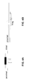
- FIG. 2 illustrates how along an electrode line of length L by external electromagnetic fields, for example in MR examinations, at various points z electrical voltages (U par or U diff ) are scattered into the electrode line. This leads to a flow of current (wave propagation) along the electrode lead in the direction of the implant and also in the direction of the distal end of the electrode lead, also referred to below as the tip. At the top, the current thus induced can lead to excessive heating.
- the voltage in the tip of the electrode is caused by the superposition of the voltages U diff and U par at different points of the line and depends on phase, attenuation and propagation speed (transfer function), it is the idea underlying the invention, by superposition of an additional signal in the electronic implant, the voltage at the electrode tip - so at the distal end of the electrode line - compensate.
- the resistance of the implant is represented as an adjustable resistance Zi, which reflects the interspersed signal (arrow) (dashed arrow) so that it overlaps with the signal at the tip to zero.
- This can be realized not only by a passive adjustable resistor (impedance) but also by an adjustable voltage source, in particular a voltage-controlled oscillator (VCO), which is located at the proximal end, as shown in FIG. 3 is shown.
- VCO voltage-controlled oscillator
- An interference field sensor is provided to provide an output signal representing a voltage, a current or a heating of the tip of the electrode line.
- the interference field sensor is designed to generate this signal from a power received at the proximal end of the electrode line.
- the interference field sensor is then integrated, for example, in the housing 12 of the heart stimulator 10.
- tuning the resistor Zi or the oscillator to voltage or current in the tip may be accomplished by a suitable detecting or transmitting device which then forms the disturbance field sensor.
- a suitable detecting or transmitting device which then forms the disturbance field sensor.
- a non-linear device may be incorporated into the tip that sends signals (in this example, harmonics) to the proximal end when current or voltage is applied.
- the resistance or oscillator at the proximal end is then adjusted by means of a control loop formed by the control unit so that these harmonics disappear.
- the respective detecting or transmitting component forms the interference field sensor at the distal end of the electrode line.
- FIG. 4A shows a possible execution.
- a diode is connected as a non-linear component with a coil in the signal path and can generate as a signal harmonics when it is traversed by current.
- the role of the coil is to counteract the development of DC voltage, so that the charge balance is maintained during stimulation.
- FIG. 4B shows a further embodiment with a non-linear component for an electrode line with a plurality of electrode poles. (eg tip and ring).
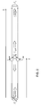
- FIG. 5 shows an embodiment of an adjustable resistor Zi as adjustable impedance between the contacts A and B, which may be installed at the proximal end of the electrode line or in the housing of the heart stimulator.
- V1 is a capacitance diode (so-called varactor), so that by setting the voltage at terminal F, the reactive component of Zi can be set.
- V2 is eg a PIN diode, so that by changing the voltage at the terminal R, the effective resistance of Zi can be adjusted.
Landscapes
- Health & Medical Sciences (AREA)
- Heart & Thoracic Surgery (AREA)
- Vascular Medicine (AREA)
- Cardiology (AREA)
- Engineering & Computer Science (AREA)
- Biomedical Technology (AREA)
- Nuclear Medicine, Radiotherapy & Molecular Imaging (AREA)
- Radiology & Medical Imaging (AREA)
- Life Sciences & Earth Sciences (AREA)
- Animal Behavior & Ethology (AREA)
- General Health & Medical Sciences (AREA)
- Public Health (AREA)
- Veterinary Medicine (AREA)
- Electrotherapy Devices (AREA)
Abstract
Description
- Die Erfindung betrifft ein permanent oder temporär implantierbares Gerät mit einem langgestreckten elektrischen Leiter.
- Solche Geräte, beispielsweise Elektrodenleitungen für die Elektrostimulation, haben den Nachteil, dass sich ihr elektrischer Leiter in einem Kernspintomografen erwärmen kann, weil die im Kernspintomografen herrschenden wechselnden Magnetfelder in dem elektrischen Leiter nicht unbeachtliche elektrische Ströme induzieren. Auch können solche induzierten Ströme über Elektrodenpole der Elektrodenleitung an umliegendes Gewebe abgegeben werden und so beispielsweise zu unerwünschten Gewebeerwärmungen führen. Deshalb können Herzschrittmacherpatienten heutzutage in der Regel nicht oder nur eingeschränkt in einem Kernspintomografen untersucht werden.
- An implantierbaren Herzschrittmachern oder Defibrillatoren (im Folgenden auch gemeinsam als Herzstimulatoren oder IPG (implantable pulse generator) bezeichnet) sind nämlich typischerweise wenigstens eine Stimulationselektrodenleitung angeschlossen, die an ihrem proximalen, zum Anschluss an den Herzschrittmacher oder Defibrillator vorgesehenen Ende einen standardisierten elektrischen Anschluss aufweist und an ihrem distalen, zur Platzierung im Herzen vorgesehenen Ende einen oder mehrere Elektrodenpole aufweist. Ein solcher Elektrodenpol dient zur Abgabe elektrischer Impulse an das Gewebe (Myokard) des Herzens oder zum Abfühlen elektrischer Felder, um im Rahmen des sogenannten Sensings eine Aktivität eines Herzens abfühlen zu können. Zu diesen Zwecken bilden Elektrodenpole typischerweise elektrisch leitende Oberflächenabschnitte einer Elektrodenleitung. Elektrodenpole sind typischerweise als Ringelektrode in Form eines Rings um die Elektrodenleitung oder in Form einer Spitzen- oder Tippelektrode am distalen Ende der Elektrodenleitung vorgesehen. Die Elektrodenpole sind über eine oder mehrere elektrische Leiter mit Kontakten des elektrischen Anschlusses der Elektrodenleitung an deren proximalem Ende elektrisch leitend verbunden. Somit verlaufen zwischen den Kontakten des elektrischen Anschlusses die Elektrodenleitungen an deren proximalen Ende und den Elektrodenpolen am distalen Ende der Elektrodenleitung ein oder mehrere elektrische Leiter, die einen oder mehrere der Elektrodenpole mit einem oder mehreren der Kontakte elektrisch verbinden. Diese elektrischen Leiter können einerseits zur Übertragung von Stimulationsimpulsen zu den Elektrodenpolen und andererseits zur Übertragung mittels der Elektrodenpole aufgenommener elektrischer Signale zum proximalen Ende der Elektrodenleitung genutzt werden und werden im Verlauf der weiteren Beschreibung auch jeweils als Funktionsleitung bezeichnet. Solche Funktionsleitungen sind für die Funktionen der jeweiligen Elektrodenleitung erforderliche elektrische Leiter und als solche der Gefahr ausgesetzt, dass in ihnen durch äußere Wechselmagnetfelder elektrische Ströme induziert werden, die beispielsweise zu einer unerwünschten Erwärmung der Funktionsleitungen oder der mit ihr verbundenen Elektrodenpole führen können oder die zur Abgabe entsprechender Ströme über die Elektrodenpole an umgebendes Gewebe und damit zu einer Erwärmung des umgebenden Gewebes führen können.
- Der Erfindung liegt die Aufgabe zugrunde, ein Gerät zu schaffen, welches das zuvor beschriebene Problem löst.
- Erfindungsgemäß wird diese Aufgabe durch ein Gerät gelöst, welches mit wenigstens einem langgestreckten elektrischen Funktionsleiter für die Übertragung von Therapiesignalen oder Diagnosesignalen oder beidem verbunden oder zu verbinden ist und eine steuerbare Spannungs- oder Stromquelle (als Kompensationssignalgenerator) oder eine einstellbare Abschlussimpedanz für den Funktionsleiter aufweist, die mit dem Funktionsleiter verbunden oder zu verbinden ist, sowie
eine Steuereinheit, die mit der Spannungs- oder Stromquelle oder der einstellbaren Abschlussimpedanz verbunden und ausgebildet ist, eine von der Spannungs- oder Stromquelle auf die Funktionsleitung aufzuprägende Spannung oder einen aufzuprägenden Strom zu steuern oder die Abschlussimpedanz einzustellen, sowie
einen Störfeldsensor, der mit der Steuereinheit verbunden und ausgebildet ist, ein ggf. vorhandenes elektromagnetisches oder magnetisches Wechselfeld zu erfassen und ein einem erfassten elektromagnetischen oder magnetischen Wechselfeld entsprechendes Ausgangssignal an die Steuereinheit zu liefern. - Hierbei ist die Steuereinheit ausgebildet, die Spannungs- oder Stromquelle in Abhängigkeit des Ausgangssignals des Störfeldsensors hinsichtlich einer ggf. auf die Funktionsleitung aufzuprägenden Spannung oder eines aufzuprägenden Stroms so zu steuern oder die einstellbare Impedanz so einzustellen, dass durch Überlagerung eines von der Strom- oder Spannungsquelle generierten oder infolge der einstellbaren Impedanz reflektierten Signals eine durch ein ggf. vorhandenes elektromagnetisches oder magnetisches Wechselfeld induzierte Spannung am distalen Ende der Elektrodenleitung zu kompensieren
- Die Erfindung schließt als ein erfinderisches Prinzip den Gedanken ein, am proximalen Ende ein entgegenwirkendes Signal aktiv oder passiv so zu induzieren, dass eine Erwärmung der Spitze teilweise oder völlig zu verhindert wird.
- Einer hiervon auch unabhängig zu realisierender Erfindungsgedanke besteht darin, an einem distalen Ende eines langgestreckten Implantats wie beispielsweise einer Elektrodenleitung einen Detektor zu platzieren, der ein Signal über Spannung, Strom oder Erwärmung der Spitze ans proximale Ende zurückleitet, um ggf. den Regelkreis zum Kompensieren der an der Spitze herrschenden Felder zu vervollständigen.
- Im Falle eines Gerätes, das eine Elektrodenleitung aufweist ist es bevorzugt, wenn die einstellbare Impedanz oder die Spannungsquelle an oder in der Nähe eines proximalen Endes der Elektrodenleitung angeordnet ist.
- Eine bevorzugte einstellbare Abschlussimpedanz enthält ein Bauteil, mit dem ein Blindwiderstand und ein Bauteil, mit dem ein Wirkwiderstand eingestellt werden kann. Das Bauteil, mit dem ein Blindwiderstand eingestellt werden kann ist vorzugsweise eine Kapazitätsdiode. Das Bauteil, mit dem ein Wirkwiderstand eingestellt werden kann ist vorzugsweise eine PIN-Diode.
- Eine bevorzugte Spannungsquelle weist einen spannungsgesteuerten Oszillator auf.
- Der Störfeldsensor ist vorzugsweise dazu ausgebildet, eine am proximalen Ende einer Elektrodenleitung empfangene Leistung zu erfassen.
- Alternativ kann der Störfeldsensor am distalen Ende einer Elektrodenleitung angeordnet sein und ein nichtlineares Bauteil aufweisen, das bei Stromfluss oder anliegender Spannung Oberwellen generiert, die dann von einer Steuereinheit am proximalen Ende der Elektrodenleitung erfasst und zur Steuerung der Spannungsquelle oder der einstellbaren Impedanz ausgewertet werden können. Das nichtlineare Bauteil kann beispielsweise eine Diode sein.
- Gemäß einer besonders bevorzugten Ausführungsvariante weist der Störfeldsensor ein nichtlineares Bauteil auf, das bei Stromfluss oder anliegender Spannung Oberwellen generiert und die Steuereinheit ist ausgebildet, die einstellbare Abschlussimpedanz oder die Spannungsquelle so einzustellen, dass diese Oberwellen verschwinden.
- Die Erfindung soll nun anhand von Ausführungsbeispielen mit Bezug auf die Figuren näher erläutert werden. Die Figuren zeigen Folgendes:
- Fig. 1
- zeigt als implantierbares medizinisches Gerät einen implantierbaren Herzstimulator 10 und eine daran angeschlossene implantierbare Elektrodenleitung 20.
- Fig. 2
- zeigt eine Elektrodenleitung in die an verschiedenen Stellen elektrische Spannungen eingestreut werden.
- Fig. 3
- zeigt ein implantierbares medizinisches Gerät mit daran angeschlossener Elektrodenleitung, die an ihrem proximalen Ende eine gesteuerte Spannungsquelle besitzt.
- Fig. 4A
- zeigt einen Störfeldsensor mit einer Diode als nichtlinearem Bauteil, der auch an einem distalen Ende einer Elektrodenleitung angeordnet sein kann.
- Fig. 4B
- zeigt ein Ausführungsbeispiel eines Störfeldsensors mit einem nichtlinearen Bauteil für eine Elektrodenleitung mit mehreren Elektrodenpolen.
- Fig. 5
- zeigt ein Ausführungsbeispiel für einen einstellbaren Widerstand Zi als einstellbare Impedanz, der am proximalen Ende einer Elektrodenleitung oder im Gehäuse eines Herzstimulators eingebaut sein kann.
- Der implantierbare Herzstimulator 10 kann ein Herzschrittmacher oder ein Kardioverter/Defibrillator (ICD) sein. Im dargestellten Ausführungsbeispiel ist der Herzstimulator 10 ein ventrikulärer Herzschrittmacher und Defibrillator. Andere bekannte Herzstimulatoren sind Zweikammerherzschrittmacher zur Stimulation des rechten Atriums und des rechten Ventrikels oder biventrikuläre Herzschrittmacher, die zusätzlich zum rechten Ventrikel auch den linken Ventrikel stimulieren können.
- Derartige Stimulatoren besitzen typischerweise ein Gehäuse 12, das im Regelfall aus Metall besteht und somit elektrisch leitend ist und als großflächiger Elektrodenpol dienen kann. An der Außenseite des Gehäuses 12 ist typischerweise ein Anschlussgehäuse 14 befestigt, das auch als Header bezeichnet wird. Ein derartiger Header weist typischerweise Kontaktbuchsen zur Aufnahme von Steckkontakten auf. Die Kontaktbuchsen besitzen elektrische Kontakte 16, die über entsprechende Leiter mit einer in dem Gehäuse 12 des Herzstimulators 10 angeordneten Elektronik verbunden sind.
- Die Elektrodenleitung 20 stellt im Sinne dieser Erfindung ebenfalls ein implantierbares medizinisches Gerät dar. Am distalen Ende der Elektrodenleitung 20 sind in an sich bekannter Manier Elektrodenpole in Form einer Spitzen- oder Tipelektrode 22 und einer in deren Nähe angeordneten Ringelektrode 24 angeordnet. Die Elektrodenpole 22 und 24 sind so ausgebildet, dass sie je nach Funktion eines Herzstimulators, an den die Elektrodenleitung 20 angeschlossen ist, zum Abfühlen elektrischer Potenziale des Herzgewebes (Myokards) dienen oder zur Abgabe elektrischer Signale, beispielsweise zur Abgabe von Stimulationsimpulsen an das sie umgebende Herzgewebe, ausgebildet sind.
Fig. 1 zeigt, wie sich die Elektrodenpole, also die Tipelektrode 22 und die Ringelektrode 24, im Anwendungsfall die Elektrodenleitung 20, im Apex eines rechten Ventrikels eines Herzens befinden. - Sowohl die Tipelektrode 22 als auch die Ringelektrode 24 sind über jeweils wenigstens einen elektrischen Leiter 26 mit einem Steckkontakt 28 am proximalen Ende der Elektrodenleitung 20 elektrisch verbunden. Der Steckkontakt 28 besitzt elektrische Kontakte, die mit den elektrischen Kontakten 16 der Kontaktbuchse im Anschlussgehäuse 14 des implantierbaren Herzstimulators korrespondieren. Die elektrischen Leiter 26 in der Elektrodenleitung 20 können als annähernd gestreckte Seilzugleiter oder als helixförmig gewendelte Leiter ausgebildet sein. Solche Leiter, die funktionale Elektrodenpole mit elektrischen Kontakten des Steckkontaktes am proximalen Ende der Elektrodenleitung 20 elektrisch leitend verbinden werden im Rahmen dieses Textes als Funktionsleiter bezeichnet, da sie beispielsweise der Therapie dienende elektrische Signale von Steckkontakt zum jeweiligen Elektrodenpol übertragen oder abgefühlte elektrische Potentiale repräsentierende Signale vom jeweiligen Elektrodenpol zum Steckkontakt führen und somit der elementaren Funktion des medizinischen Gerätes dienen.
- Die elektrischen Leiter 26, die die Elektrodenpole 22 bzw. 24 mit den elektrischen Kontakten des Steckers 28 der Elektrodenleitung 20 verbinden, sind über den größten Teil ihrer Länge von einer isolierenden Hülle umgeben, so dass ein elektrischer Kontakt zum Gewebe des Herzens gezielt über die Elektrodenpole zustande kommt.
- Neben den Elektrodenpolen 22 und 24, die typischerweise der (in diesem Fall ventrikulären) Stimulation des Herzgewebes dienen, weist die Elektrodenleitung 20 auch noch zwei großflächigere Elektrodenpole 30 und 32 auf, die als Defibrillationselektroden dienen und von wenigstens einem blank liegendem helixartig gewendelten Draht gebildet sind.
- Es sei darauf hingewiesen, dass die Erfindung im Rahmen dieses Ausführungsbeispiels anhand eines rechtsventrikulären Herzschrittmachers und Defibrillators erläutert wird. Als medizinisches Gerät im Sinne der Erfindung kann grundsätzlich aber beispielsweise auch eine Ablationselektrodenleitung dienen, die im Anwendungsfall ebenfalls bis ins Herz eines Patienten hineinragt und die von einem außerhalb des Patienten angeordneten Gerät gesteuert wird und hierzu mit diesem verbunden ist.
-
Figur 2 veranschaulicht, wie entlang einer Elektrodenleitung der Länge L durch äußere elektromagnetische Felder, z.B. bei MR-Untersuchungen, an verschiedenen Stellen z elektrische Spannungen (Upar oder Udiff) in die Elektrodenleitung eingestreut werden. Dies führt zu einem Stromfluss (Wellenausbreitung) entlang der Elektrodenleitung in die Richtung zum Implantat und auch in die Richtung zum distalen Ende der Elektrodenleitung, im Folgenden auch als Spitze bezeichnet. An der Spitze kann der so induzierte Strom zu einer übermäßigen Erwärmung führen. - Da die Spannung in der Spitze der Elektrode durch die Überlagerung der Spannungen Udiff und Upar an verschiedenen Stellen der Leitung entsteht und sich nach Phase, Dämpfung und Ausbreitungsgeschwindigkeit richtet (Übertragungsfunktion), ist es die der Erfindung zugrundeliegende Idee, durch Überlagerung eines zusätzlichen Signals im elektronischen Implantat die Spannung an der Elektrodenspitze - also am distalen Ende er Elektrodenleitung - auszugleichen.
- In
Figur 2 ist der Widerstand des Implantats als einstellbarer Widerstand Zi dargestellt, der das eingestreute Signal (Pfeil) so reflektiert (gestrichelter Pfeil), dass es sich mit dem Signal an der Spitze zu null überlagert. Dies kann außer durch einen passiven einstellbaren Widerstand (Impedanz) auch durch eine einstellbare Spannungsquelle, insbesondere einen spannungsgesteuerten Oszillator (VCO, voltage controlled oscillator) realisiert sein, der sich am proximalen Ende befindet, wie dies inFigur 3 dargestellt ist. - Ein Störfeldsensor ist dazu vorgesehen, ein Ausgangssignal zu liefern, das eine Spannung, einen Strom oder eine Erwärmung der Spitze der Elektrodenleitung repräsentiert.
- Gemäß einer Ausführungsvariante ist der Störfeldsensor dazu ausgebildet, dieses Signal aus einer am proximalen Ende der Elektrodenleitung empfangenen Leistung zu generieren. Der Störfeldsensor ist dann beispielsweise in das Gehäuse 12 des Herzstimulators 10 integriert.
- Außer durch Detektion der empfangenen Leistung am proximalen Ende kann die Abstimmung des Widerstands Zi oder des Oszillators auch nach Spannung oder Strom in der Spitze durch ein geeignetes detektierendes oder sendendes Bauteil erfolgen, das dann den Störfeldsensor bildet. Z.B. kann ein nichtlineares Bauteil in die Spitze eingebaut werden, dass bei Stromfluss oder anliegender Spannung Signale (in diesem Beispiel Oberwellen) an das proximale Ende sendet. Der Widerstand oder Oszillator am proximalen Ende wird dann mittels eines von der Steuereinheit gebildeten Regelkreises so eingestellt, dass diese Oberwellen verschwinden. In diesem Fall bildet das jeweilige detektierende oder sendende Bauteil am distalen Ende der Elektrodenleitung den Störfeldsensor.
-
Figur 4A zeigt eine mögliche Ausführung. Hier wird eine Diode als nichtlineares Bauteil mit einer Spule in den Signalweg geschaltet und kann als Signal Oberwellen erzeugen, wenn sie von Strom durchflossen wird. Die Spule hat die Aufgabe, der Entstehung von Gleichspannung entgegenzuwirken, damit die Ladungsbilanz bei der Stimulation erhalten bleibt.Figur 4B zeigt ein weiteres Ausführungsbeispiel mit einem nichtlinearen Bauteil für eine Elektrodenleitung mit mehreren Elektrodenpolen. (z.B. Tip und Ring). -
Figur 5 zeigt ein Ausführungsbeispiel für einen einstellbaren Widerstand Zi als einstellbare Impedanz zwischen den Kontakten A und B, der am proximalen Ende der Elektrodenleitung oder im Gehäuse des Herzstimulators eingebaut sein kann. V1 ist eine Kapazitätsdiode (sog. Varaktor), so dass durch Einstellung der Spannung am Anschluss F der Blindanteil von Zi eingestellt werden kann. V2 ist z.B. eine PIN-Diode, so dass durch Veränderung der Spannung am Anschluss R der Wirkwiderstand von Zi eingestellt werden kann. - Diese Entgegenwirkung funktioniert besonders gut, wenn die Dämpfung von Wellen auf der Elektrodenleitung gering ist, so dass am proximalen Ende viel Energie ankommt und eine starke Rückwirkung des proximalen Endes auf das distale Ende der Elektrodenleitung zu erwarten ist.
Claims (8)
- Temporär oder permanent implantierbares medizinisches Gerät, dass mit wenigstens einem langgestreckten elektrischen Funktionsleiter für die Übertragung von Therapiesignalen oder Diagnosesignalen oder beidem verbunden oder zu verbinden ist,
dadurch gekennzeichnet, dass das medizinische Gerät
eine steuerbare Spannungs- oder Stromquelle oder eine einstellbare Abschlussimpedanz für den Funktionsleiter aufweist, die mit dem Funktionsleiter verbunden oder zu verbinden ist, sowie
eine Steuereinheit, die mit der Spannungs- oder Stromquelle oder der einstellbaren Abschlussimpedanz verbunden und ausgebildet ist, eine von der Spannungs- oder Stromquelle auf die Funktionsleitung aufzuprägende Spannung oder einen aufzuprägenden Strom zu steuern oder die Abschlussimpedanz einzustellen, sowie
einen Störfeldsensor, der mit der Steuereinheit verbunden und ausgebildet ist, ein ggf. vorhandenes elektromagnetisches oder magnetisches Wechselfeld zu erfassen und ein einem erfassten elektromagnetischen oder magnetischen Wechselfeld entsprechendes Ausgangssignal an die Steuereinheit zu liefern,
wobei die Steuereinheit ausgebildet ist, die Spannungs- oder Stromquelle in Abhängigkeit des Ausgangssignals des Störfeldsensors hinsichtlich einer ggf. auf die Funktionsleitung aufzuprägenden Spannung oder eines aufzuprägenden Stroms zu steuern oder die einstellbare Impedanz so einzustellen, dass durch Überlagerung eines von der Strom- oder Spannungsquelle generierten oder infolge der einstellbaren Impedanz reflektierten Signals eine durch ein ggf. vorhandenes elektromagnetisches oder magnetisches Wechselfeld induzierte Spannung am distalen Ende der Elektrodenleitung zu kompensieren. - Gerät nach Anspruch 1, dadurch gekennzeichnet, dass das Gerät eine Elektrodenleitung aufweist und die einstellbare Impedanz oder die Spannungsquelle an oder in der Nähe eines proximalen Endes der Elektrodenleitung angeordnet ist.
- Gerät nach Anspruch 1 oder 2, dadurch gekennzeichnet, dass die einstellbare Abschlussimpedanz eine Kapazitätsdiode und eine PIN-Diode enthält.
- Gerät nach Anspruch 1 oder 2, dadurch gekennzeichnet, dass die Spannungsquelle einen spannungsgesteuerten Oszillator aufweist.
- Gerät nach einem der Ansprüche 1 bis 4, dadurch gekennzeichnet, dass der Störfeldsensor dazu ausgebildet ist, eine am proximalen Ende einer Elektrodenleitung empfangene Leistung zu erfassen.
- Gerät nach einem der Ansprüche 1 bis 4, dadurch gekennzeichnet, dass der Störfeldsensor am distalen Ende einer Elektrodenleitung angeordnet ist und ein nichtlineares Bauteil aufweist.
- Gerät nach Anspruch 6, dadurch gekennzeichnet, dass das nichtlineare Bauteil eine Diode ist.
- Gerät nach einem der Ansprüche 1 bis 7, dadurch gekennzeichnet, dass der Störfeldsensor ein nichtlineares Bauteil aufweist, das bei Stromfluss oder anliegender Spannung Oberwellen generiert und die Steuereinheit ausgebildet ist, die einstellbare Abschlussimpedanz oder die Spannungsquelle so einzustellen, dass diese Oberwellen verschwinden
Applications Claiming Priority (1)
| Application Number | Priority Date | Filing Date | Title |
|---|---|---|---|
| US201061425253P | 2010-12-21 | 2010-12-21 |
Publications (2)
| Publication Number | Publication Date |
|---|---|
| EP2468353A1 true EP2468353A1 (de) | 2012-06-27 |
| EP2468353B1 EP2468353B1 (de) | 2017-05-17 |
Family
ID=45318979
Family Applications (1)
| Application Number | Title | Priority Date | Filing Date |
|---|---|---|---|
| EP11193144.0A Not-in-force EP2468353B1 (de) | 2010-12-21 | 2011-12-13 | Implantierbares Gerät |
Country Status (2)
| Country | Link |
|---|---|
| US (1) | US8423138B2 (de) |
| EP (1) | EP2468353B1 (de) |
Families Citing this family (4)
| Publication number | Priority date | Publication date | Assignee | Title |
|---|---|---|---|---|
| AU2015249832B2 (en) * | 2014-04-25 | 2017-08-24 | Boston Scientific Neuromodulation Corporation | System and method for electrical pulse charge compensation for implantable medical device capacitance loading effects |
| WO2020030453A1 (en) | 2018-08-08 | 2020-02-13 | Koninklijke Philips N.V. | Reducing sensor interference in a medical device |
| EP3632335A1 (de) * | 2018-10-05 | 2020-04-08 | Koninklijke Philips N.V. | Reduzierung von sensorstörungen in einer medizinischen vorrichtung |
| KR102344771B1 (ko) * | 2020-04-28 | 2021-12-30 | 사회복지법인 삼성생명공익재단 | 신체 기관에 전기 자극을 인가하는 전극선 구조체 및 이를 이용한 전극 시스템 |
Citations (2)
| Publication number | Priority date | Publication date | Assignee | Title |
|---|---|---|---|---|
| US20040124838A1 (en) * | 2001-03-30 | 2004-07-01 | Duerk Jeffrey L | Wireless detuning of a resonant circuit in an mr imaging system |
| US20040263172A1 (en) * | 2003-06-24 | 2004-12-30 | Biophan Technologies, Inc. | Magnetic resonance imaging interference immune device |
-
2011
- 2011-12-01 US US13/309,398 patent/US8423138B2/en not_active Expired - Fee Related
- 2011-12-13 EP EP11193144.0A patent/EP2468353B1/de not_active Not-in-force
Patent Citations (2)
| Publication number | Priority date | Publication date | Assignee | Title |
|---|---|---|---|---|
| US20040124838A1 (en) * | 2001-03-30 | 2004-07-01 | Duerk Jeffrey L | Wireless detuning of a resonant circuit in an mr imaging system |
| US20040263172A1 (en) * | 2003-06-24 | 2004-12-30 | Biophan Technologies, Inc. | Magnetic resonance imaging interference immune device |
Also Published As
| Publication number | Publication date |
|---|---|
| US8423138B2 (en) | 2013-04-16 |
| US20120158077A1 (en) | 2012-06-21 |
| EP2468353B1 (de) | 2017-05-17 |
Similar Documents
| Publication | Publication Date | Title |
|---|---|---|
| EP2130566B1 (de) | Langgestrecktes Implantat mit externer Energieeinkopplung | |
| EP1923094A1 (de) | Elektrodenkatheter zu Interventionszwecken | |
| EP2465572B1 (de) | MRT-kompatible implantierbare Leitung | |
| EP2502646B1 (de) | Implantierbares Gerät | |
| EP2578268B1 (de) | Temperatursensor für ein implantierbares medizinisches Gerät | |
| EP2468353B1 (de) | Implantierbares Gerät | |
| EP2465569B1 (de) | Implantierbares Gerät | |
| EP2478932B1 (de) | Implantierbares Gerät | |
| EP2110156B1 (de) | Feldentkopplungs-Element zur Verwendung mit einer implantierbaren Leitung und implantierbares medizinisches Gerät | |
| EP2446922B1 (de) | Implantierbare Leiter mit zusätzlichen Leitern zur Feldentkopplung | |
| EP2465573B1 (de) | Implantierbares Gerät | |
| EP2848282B1 (de) | Implantierbares Gerät | |
| EP2478933A2 (de) | Implantierbares Gerät | |
| EP2465570B1 (de) | Implantierbares Gerät | |
| EP3025756B1 (de) | Im aktiven implantat integrierte elektrodenverlängerung | |
| EP2468356B1 (de) | Implantierbares Gerät | |
| EP2985054B1 (de) | Implantierbares gerät mit elektrischem filter | |
| EP2465571B1 (de) | Implantierbares Gerät | |
| EP2505229A2 (de) | Implantierbares Gerät | |
| EP3009165A1 (de) | Implantierbare elektrische leitung |
Legal Events
| Date | Code | Title | Description |
|---|---|---|---|
| AK | Designated contracting states |
Kind code of ref document: A1 Designated state(s): AL AT BE BG CH CY CZ DE DK EE ES FI FR GB GR HR HU IE IS IT LI LT LU LV MC MK MT NL NO PL PT RO RS SE SI SK SM TR |
|
| AX | Request for extension of the european patent |
Extension state: BA ME |
|
| PUAI | Public reference made under article 153(3) epc to a published international application that has entered the european phase |
Free format text: ORIGINAL CODE: 0009012 |
|
| 17P | Request for examination filed |
Effective date: 20121212 |
|
| 17Q | First examination report despatched |
Effective date: 20151008 |
|
| RIC1 | Information provided on ipc code assigned before grant |
Ipc: A61N 1/05 20060101AFI20161206BHEP Ipc: A61N 1/39 20060101ALI20161206BHEP Ipc: A61N 1/36 20060101ALI20161206BHEP Ipc: A61N 1/08 20060101ALN20161206BHEP Ipc: A61N 1/37 20060101ALN20161206BHEP |
|
| GRAP | Despatch of communication of intention to grant a patent |
Free format text: ORIGINAL CODE: EPIDOSNIGR1 |
|
| RIC1 | Information provided on ipc code assigned before grant |
Ipc: A61N 1/36 20060101ALI20161212BHEP Ipc: A61N 1/39 20060101ALI20161212BHEP Ipc: A61N 1/08 20060101ALN20161212BHEP Ipc: A61N 1/37 20060101ALN20161212BHEP Ipc: A61N 1/05 20060101AFI20161212BHEP |
|
| INTG | Intention to grant announced |
Effective date: 20170119 |
|
| GRAS | Grant fee paid |
Free format text: ORIGINAL CODE: EPIDOSNIGR3 |
|
| GRAA | (expected) grant |
Free format text: ORIGINAL CODE: 0009210 |
|
| AK | Designated contracting states |
Kind code of ref document: B1 Designated state(s): AL AT BE BG CH CY CZ DE DK EE ES FI FR GB GR HR HU IE IS IT LI LT LU LV MC MK MT NL NO PL PT RO RS SE SI SK SM TR |
|
| REG | Reference to a national code |
Ref country code: GB Ref legal event code: FG4D Free format text: NOT ENGLISH |
|
| REG | Reference to a national code |
Ref country code: CH Ref legal event code: EP |
|
| REG | Reference to a national code |
Ref country code: IE Ref legal event code: FG4D Free format text: LANGUAGE OF EP DOCUMENT: GERMAN |
|
| REG | Reference to a national code |
Ref country code: AT Ref legal event code: REF Ref document number: 893920 Country of ref document: AT Kind code of ref document: T Effective date: 20170615 |
|
| REG | Reference to a national code |
Ref country code: DE Ref legal event code: R096 Ref document number: 502011012260 Country of ref document: DE |
|
| REG | Reference to a national code |
Ref country code: NL Ref legal event code: MP Effective date: 20170517 |
|
| REG | Reference to a national code |
Ref country code: LT Ref legal event code: MG4D |
|
| PG25 | Lapsed in a contracting state [announced via postgrant information from national office to epo] |
Ref country code: FI Free format text: LAPSE BECAUSE OF FAILURE TO SUBMIT A TRANSLATION OF THE DESCRIPTION OR TO PAY THE FEE WITHIN THE PRESCRIBED TIME-LIMIT Effective date: 20170517 Ref country code: HR Free format text: LAPSE BECAUSE OF FAILURE TO SUBMIT A TRANSLATION OF THE DESCRIPTION OR TO PAY THE FEE WITHIN THE PRESCRIBED TIME-LIMIT Effective date: 20170517 Ref country code: GR Free format text: LAPSE BECAUSE OF FAILURE TO SUBMIT A TRANSLATION OF THE DESCRIPTION OR TO PAY THE FEE WITHIN THE PRESCRIBED TIME-LIMIT Effective date: 20170818 Ref country code: ES Free format text: LAPSE BECAUSE OF FAILURE TO SUBMIT A TRANSLATION OF THE DESCRIPTION OR TO PAY THE FEE WITHIN THE PRESCRIBED TIME-LIMIT Effective date: 20170517 Ref country code: NO Free format text: LAPSE BECAUSE OF FAILURE TO SUBMIT A TRANSLATION OF THE DESCRIPTION OR TO PAY THE FEE WITHIN THE PRESCRIBED TIME-LIMIT Effective date: 20170817 Ref country code: LT Free format text: LAPSE BECAUSE OF FAILURE TO SUBMIT A TRANSLATION OF THE DESCRIPTION OR TO PAY THE FEE WITHIN THE PRESCRIBED TIME-LIMIT Effective date: 20170517 |
|
| PG25 | Lapsed in a contracting state [announced via postgrant information from national office to epo] |
Ref country code: PL Free format text: LAPSE BECAUSE OF FAILURE TO SUBMIT A TRANSLATION OF THE DESCRIPTION OR TO PAY THE FEE WITHIN THE PRESCRIBED TIME-LIMIT Effective date: 20170517 Ref country code: SE Free format text: LAPSE BECAUSE OF FAILURE TO SUBMIT A TRANSLATION OF THE DESCRIPTION OR TO PAY THE FEE WITHIN THE PRESCRIBED TIME-LIMIT Effective date: 20170517 Ref country code: LV Free format text: LAPSE BECAUSE OF FAILURE TO SUBMIT A TRANSLATION OF THE DESCRIPTION OR TO PAY THE FEE WITHIN THE PRESCRIBED TIME-LIMIT Effective date: 20170517 Ref country code: BG Free format text: LAPSE BECAUSE OF FAILURE TO SUBMIT A TRANSLATION OF THE DESCRIPTION OR TO PAY THE FEE WITHIN THE PRESCRIBED TIME-LIMIT Effective date: 20170817 Ref country code: IS Free format text: LAPSE BECAUSE OF FAILURE TO SUBMIT A TRANSLATION OF THE DESCRIPTION OR TO PAY THE FEE WITHIN THE PRESCRIBED TIME-LIMIT Effective date: 20170917 Ref country code: NL Free format text: LAPSE BECAUSE OF FAILURE TO SUBMIT A TRANSLATION OF THE DESCRIPTION OR TO PAY THE FEE WITHIN THE PRESCRIBED TIME-LIMIT Effective date: 20170517 Ref country code: RS Free format text: LAPSE BECAUSE OF FAILURE TO SUBMIT A TRANSLATION OF THE DESCRIPTION OR TO PAY THE FEE WITHIN THE PRESCRIBED TIME-LIMIT Effective date: 20170517 |
|
| PG25 | Lapsed in a contracting state [announced via postgrant information from national office to epo] |
Ref country code: SK Free format text: LAPSE BECAUSE OF FAILURE TO SUBMIT A TRANSLATION OF THE DESCRIPTION OR TO PAY THE FEE WITHIN THE PRESCRIBED TIME-LIMIT Effective date: 20170517 Ref country code: EE Free format text: LAPSE BECAUSE OF FAILURE TO SUBMIT A TRANSLATION OF THE DESCRIPTION OR TO PAY THE FEE WITHIN THE PRESCRIBED TIME-LIMIT Effective date: 20170517 Ref country code: DK Free format text: LAPSE BECAUSE OF FAILURE TO SUBMIT A TRANSLATION OF THE DESCRIPTION OR TO PAY THE FEE WITHIN THE PRESCRIBED TIME-LIMIT Effective date: 20170517 Ref country code: RO Free format text: LAPSE BECAUSE OF FAILURE TO SUBMIT A TRANSLATION OF THE DESCRIPTION OR TO PAY THE FEE WITHIN THE PRESCRIBED TIME-LIMIT Effective date: 20170517 Ref country code: CZ Free format text: LAPSE BECAUSE OF FAILURE TO SUBMIT A TRANSLATION OF THE DESCRIPTION OR TO PAY THE FEE WITHIN THE PRESCRIBED TIME-LIMIT Effective date: 20170517 |
|
| REG | Reference to a national code |
Ref country code: DE Ref legal event code: R097 Ref document number: 502011012260 Country of ref document: DE |
|
| PG25 | Lapsed in a contracting state [announced via postgrant information from national office to epo] |
Ref country code: SM Free format text: LAPSE BECAUSE OF FAILURE TO SUBMIT A TRANSLATION OF THE DESCRIPTION OR TO PAY THE FEE WITHIN THE PRESCRIBED TIME-LIMIT Effective date: 20170517 Ref country code: IT Free format text: LAPSE BECAUSE OF FAILURE TO SUBMIT A TRANSLATION OF THE DESCRIPTION OR TO PAY THE FEE WITHIN THE PRESCRIBED TIME-LIMIT Effective date: 20170517 |
|
| PGFP | Annual fee paid to national office [announced via postgrant information from national office to epo] |
Ref country code: CH Payment date: 20171221 Year of fee payment: 7 Ref country code: IE Payment date: 20171215 Year of fee payment: 7 |
|
| PLBE | No opposition filed within time limit |
Free format text: ORIGINAL CODE: 0009261 |
|
| STAA | Information on the status of an ep patent application or granted ep patent |
Free format text: STATUS: NO OPPOSITION FILED WITHIN TIME LIMIT |
|
| 26N | No opposition filed |
Effective date: 20180220 |
|
| PGFP | Annual fee paid to national office [announced via postgrant information from national office to epo] |
Ref country code: DE Payment date: 20171222 Year of fee payment: 7 |
|
| PG25 | Lapsed in a contracting state [announced via postgrant information from national office to epo] |
Ref country code: SI Free format text: LAPSE BECAUSE OF FAILURE TO SUBMIT A TRANSLATION OF THE DESCRIPTION OR TO PAY THE FEE WITHIN THE PRESCRIBED TIME-LIMIT Effective date: 20170517 |
|
| GBPC | Gb: european patent ceased through non-payment of renewal fee |
Effective date: 20171213 |
|
| PG25 | Lapsed in a contracting state [announced via postgrant information from national office to epo] |
Ref country code: MT Free format text: LAPSE BECAUSE OF FAILURE TO SUBMIT A TRANSLATION OF THE DESCRIPTION OR TO PAY THE FEE WITHIN THE PRESCRIBED TIME-LIMIT Effective date: 20170517 Ref country code: LU Free format text: LAPSE BECAUSE OF NON-PAYMENT OF DUE FEES Effective date: 20171213 |
|
| REG | Reference to a national code |
Ref country code: FR Ref legal event code: ST Effective date: 20180831 |
|
| REG | Reference to a national code |
Ref country code: BE Ref legal event code: MM Effective date: 20171231 |
|
| PG25 | Lapsed in a contracting state [announced via postgrant information from national office to epo] |
Ref country code: FR Free format text: LAPSE BECAUSE OF NON-PAYMENT OF DUE FEES Effective date: 20180102 |
|
| PG25 | Lapsed in a contracting state [announced via postgrant information from national office to epo] |
Ref country code: BE Free format text: LAPSE BECAUSE OF NON-PAYMENT OF DUE FEES Effective date: 20171231 Ref country code: GB Free format text: LAPSE BECAUSE OF NON-PAYMENT OF DUE FEES Effective date: 20171213 |
|
| REG | Reference to a national code |
Ref country code: AT Ref legal event code: MM01 Ref document number: 893920 Country of ref document: AT Kind code of ref document: T Effective date: 20171213 |
|
| PG25 | Lapsed in a contracting state [announced via postgrant information from national office to epo] |
Ref country code: AT Free format text: LAPSE BECAUSE OF NON-PAYMENT OF DUE FEES Effective date: 20171213 |
|
| PG25 | Lapsed in a contracting state [announced via postgrant information from national office to epo] |
Ref country code: HU Free format text: LAPSE BECAUSE OF FAILURE TO SUBMIT A TRANSLATION OF THE DESCRIPTION OR TO PAY THE FEE WITHIN THE PRESCRIBED TIME-LIMIT; INVALID AB INITIO Effective date: 20111213 Ref country code: MC Free format text: LAPSE BECAUSE OF FAILURE TO SUBMIT A TRANSLATION OF THE DESCRIPTION OR TO PAY THE FEE WITHIN THE PRESCRIBED TIME-LIMIT Effective date: 20170517 |
|
| REG | Reference to a national code |
Ref country code: DE Ref legal event code: R119 Ref document number: 502011012260 Country of ref document: DE |
|
| REG | Reference to a national code |
Ref country code: CH Ref legal event code: PL |
|
| REG | Reference to a national code |
Ref country code: IE Ref legal event code: MM4A |
|
| PG25 | Lapsed in a contracting state [announced via postgrant information from national office to epo] |
Ref country code: DE Free format text: LAPSE BECAUSE OF NON-PAYMENT OF DUE FEES Effective date: 20190702 Ref country code: CY Free format text: LAPSE BECAUSE OF NON-PAYMENT OF DUE FEES Effective date: 20170517 Ref country code: IE Free format text: LAPSE BECAUSE OF NON-PAYMENT OF DUE FEES Effective date: 20181213 |
|
| PG25 | Lapsed in a contracting state [announced via postgrant information from national office to epo] |
Ref country code: MK Free format text: LAPSE BECAUSE OF FAILURE TO SUBMIT A TRANSLATION OF THE DESCRIPTION OR TO PAY THE FEE WITHIN THE PRESCRIBED TIME-LIMIT Effective date: 20170517 |
|
| PG25 | Lapsed in a contracting state [announced via postgrant information from national office to epo] |
Ref country code: CH Free format text: LAPSE BECAUSE OF NON-PAYMENT OF DUE FEES Effective date: 20181231 Ref country code: LI Free format text: LAPSE BECAUSE OF NON-PAYMENT OF DUE FEES Effective date: 20181231 |
|
| PG25 | Lapsed in a contracting state [announced via postgrant information from national office to epo] |
Ref country code: TR Free format text: LAPSE BECAUSE OF FAILURE TO SUBMIT A TRANSLATION OF THE DESCRIPTION OR TO PAY THE FEE WITHIN THE PRESCRIBED TIME-LIMIT Effective date: 20170517 |
|
| PG25 | Lapsed in a contracting state [announced via postgrant information from national office to epo] |
Ref country code: PT Free format text: LAPSE BECAUSE OF FAILURE TO SUBMIT A TRANSLATION OF THE DESCRIPTION OR TO PAY THE FEE WITHIN THE PRESCRIBED TIME-LIMIT Effective date: 20170517 |
|
| PG25 | Lapsed in a contracting state [announced via postgrant information from national office to epo] |
Ref country code: AL Free format text: LAPSE BECAUSE OF FAILURE TO SUBMIT A TRANSLATION OF THE DESCRIPTION OR TO PAY THE FEE WITHIN THE PRESCRIBED TIME-LIMIT Effective date: 20170517 |