EP2468197A1 - Stabilization device for stabilizing vertebrae or bone parts - Google Patents
Stabilization device for stabilizing vertebrae or bone parts Download PDFInfo
- Publication number
- EP2468197A1 EP2468197A1 EP10196866A EP10196866A EP2468197A1 EP 2468197 A1 EP2468197 A1 EP 2468197A1 EP 10196866 A EP10196866 A EP 10196866A EP 10196866 A EP10196866 A EP 10196866A EP 2468197 A1 EP2468197 A1 EP 2468197A1
- Authority
- EP
- European Patent Office
- Prior art keywords
- head
- rod
- locking ring
- stabilization device
- rods
- Prior art date
- Legal status (The legal status is an assumption and is not a legal conclusion. Google has not performed a legal analysis and makes no representation as to the accuracy of the status listed.)
- Granted
Links
Images


Classifications
-
- A—HUMAN NECESSITIES
- A61—MEDICAL OR VETERINARY SCIENCE; HYGIENE
- A61B—DIAGNOSIS; SURGERY; IDENTIFICATION
- A61B17/00—Surgical instruments, devices or methods
- A61B17/56—Surgical instruments or methods for treatment of bones or joints; Devices specially adapted therefor
- A61B17/58—Surgical instruments or methods for treatment of bones or joints; Devices specially adapted therefor for osteosynthesis, e.g. bone plates, screws or setting implements
- A61B17/68—Internal fixation devices, including fasteners and spinal fixators, even if a part thereof projects from the skin
- A61B17/70—Spinal positioners or stabilisers, e.g. stabilisers comprising fluid filler in an implant
-
- A—HUMAN NECESSITIES
- A61—MEDICAL OR VETERINARY SCIENCE; HYGIENE
- A61B—DIAGNOSIS; SURGERY; IDENTIFICATION
- A61B17/00—Surgical instruments, devices or methods
- A61B17/56—Surgical instruments or methods for treatment of bones or joints; Devices specially adapted therefor
- A61B17/58—Surgical instruments or methods for treatment of bones or joints; Devices specially adapted therefor for osteosynthesis, e.g. bone plates, screws or setting implements
- A61B17/68—Internal fixation devices, including fasteners and spinal fixators, even if a part thereof projects from the skin
- A61B17/70—Spinal positioners or stabilisers, e.g. stabilisers comprising fluid filler in an implant
- A61B17/7001—Screws or hooks combined with longitudinal elements which do not contact vertebrae
- A61B17/7035—Screws or hooks, wherein a rod-clamping part and a bone-anchoring part can pivot relative to each other
- A61B17/7037—Screws or hooks, wherein a rod-clamping part and a bone-anchoring part can pivot relative to each other wherein pivoting is blocked when the rod is clamped
-
- A—HUMAN NECESSITIES
- A61—MEDICAL OR VETERINARY SCIENCE; HYGIENE
- A61B—DIAGNOSIS; SURGERY; IDENTIFICATION
- A61B17/00—Surgical instruments, devices or methods
- A61B17/56—Surgical instruments or methods for treatment of bones or joints; Devices specially adapted therefor
- A61B17/58—Surgical instruments or methods for treatment of bones or joints; Devices specially adapted therefor for osteosynthesis, e.g. bone plates, screws or setting implements
- A61B17/68—Internal fixation devices, including fasteners and spinal fixators, even if a part thereof projects from the skin
- A61B17/84—Fasteners therefor or fasteners being internal fixation devices
- A61B17/86—Pins or screws or threaded wires; nuts therefor
Definitions
- the invention relates to a stabilization device for stabilizing vertebrae or bones that includes a bone anchoring device and at least two stabilization rods of different diameter.
- bone anchoring devices For stabilizing the spinal column bone anchoring devices are known that comprise a shaft to be anchored in the bone and a head to be connected to a rod. Usually, a rod connects several bone anchoring devices. Depending on the medical indication and the region of the spine that is to be stabilized rods with different diameters are required. The diameter of the rods ranges from 3mm to more than 6mm. Generally, the diameter of the rod used in the lower part of the spine is larger than the diameter of the rod used in the upper part of the spine.
- the cervical-thoracic region of the spine rods with a diameter of 3mm to 3.5mm in the transitional zones between the cervical-thoracic and the thoracic-lumbar region rods with a diameter of 3.5mm to 4.5mm, in the thoracic-lumbar region rods of usually 4.5mm to 5.5mm and the lumbar-sacral region rods with a diameter of 5mm to 6.35mm are necessary.
- US 5,873,878 discloses an anchoring member for attachment to a vertebra and for use with a first rod having a first diameter and a second rod having a second, smaller diameter.
- the anchoring member comprises an insert member which can be inserted into the head of the anchoring member so as to allow the insertion of a rod with a smaller diameter.
- EP 2 070 485 Al describes a monoaxial bone anchoring device and a polyaxial bone anchoring device each of which can be used with rods of different diameters.
- a modular system can be provided that allows to combine various anchoring elements with any suitable receiving part and any suitable rod on demand depending on the actual clinical requirements. This reduces the costs of polyaxial screws, reduces the inventory and gives the surgeon a substantial choice of implants.
- the assembly of the stabilization device can be carried out by any specialist, for example, by the surgeon or any personnel assisting him before or during surgery.
- the anchoring device has an advantage in that it provides a safe clamping of any of the rods having a different diameter.
- the clamping force does not depend on the diameter of the rod. Also, the clamping of rods of different diameter is achieved in a stepless manner.
- the bone anchoring device is constructed to minimize the number of parts. Hence it does not require additional parts to allow the fixation of different rods.
- the stabilization device can be used for example for the correction of scoliosis in children.
- a child having a scoliosis correction grows up, it may be necessary to adapt the scoliosis correction device.
- With the stabilization device according to the invention it is possible to replace the originally used rods in a second surgery with the bone anchors remaining anchored in the vertebrae.
- the stabilization device includes a bone anchoring element 1 in the form of a bone screw having a threaded shaft 2 and a head 3 with a curved surface portion.
- the head is spherical segment-shaped.
- the head 3 has a recess 4 for engagement with a tool.
- the stabilization device also comprises a receiving part 5 for receiving a first rod 100 to connect it to the bone anchoring element 1.
- a fixation element 7 in the form of an inner screw is provided for fixing the rod 100 in the receiving part 5.
- the stabilization device includes a locking ring 8 for locking the head 3 in the receiving part 5.
- At least one further rod (not shown) is provided that has a diameter different from the diameter of the first rod.
- the rods have a circular cross-section. Also, the rods have a substantially smooth surface.
- the receiving part 5 will be explained with reference to Figs. 1 to 4 . It comprises a rod receiving portion 9, which is substantially cylindrical and which has a first end 9a and an opposite second end 9b. A coaxial first bore 10 is provided at the second end 9b as shown in Figs. 3 and 8 . The diameter of the first bore 10 is smaller than the diameter of the head 3 of the bone anchoring element.
- the rod receiving portion 9 further has a coaxial second bore 11 extending from the first end 9a to a distance from the second end 9b. The diameter of the second bore 11 is larger than that of the first bore 10.
- a substantially U-shaped recess 12 extends from the first end 9a in the direction of the second end 9b in the rod receiving portion, the diameter of the recess 12 being larger as the diameter of any of the rods so that the rod 100 and any other rod of the stabilization device can be placed in the recess and can be guided therein.
- the internal thread can be a metric thread, a flat thread, a negative angle thread, a saw-tooth thread, or any other thread form.
- a thread form such as a flat thread or negative angle thread is used, which prevents splaying of the legs 12a, 12b when the inner screw 7 is screwed-in.
- the depth of the recess 12 is such that the rod 100 oreach of the further rods of the stabilization device and the inner screw 7 can be inserted between the legs.
- cut-outs 15 are provided in the rod receiving portion on either end of the channel formed by the recess 12.
- a groove 16 is provided, which extends in a circumferential direction and serves for engagement with a portion of the locking ring 8.
- the receiving part 5 comprises a head receiving portion 17 providing an accommodation space for the head 3 of the bone anchoring element 1.
- the head receiving portion 17 has a greatest outer diameter, which is smaller than the greatest outer diameter of the rod receiving portion 9.
- An internal hollow section 18 forms a seat for the head 3 of the bone anchoring element 1 and is open via the opening 19 to the free end 17b of the head receiving portion.
- the hollow section 18 is adapted in its shape to the shape of the head 3, in the embodiment shown, it is a spherical section to accommodate the spherical head 3.
- the hollow section 18 is configured to encompass the head 3 of the bone anchoring element from the side covering a region including the largest diameter of the head 3.
- a plurality of slits 20 are provided in the head receiving portion 17, which are open to the free end 17b.
- the slits 20 render the head receiving portion 17 flexible so that it can be compressed to clamp and finally lock the head 3 in the hollow internal portion 18 by means of friction.
- the number and size of slits 20 is provided depending on the desired flexibility of the head receiving portion 17.
- the flexibility of the head receiving portion 17 is such that the head 3 of the anchoring element can be inserted by expanding the head receiving portion and that it can be clamped by compressing the head receiving portion.
- the outer surface of the head receiving portion 17 has a first section 21, with an outer diameter which increases towards free end 17b, for example in an outwardly curved manner. Adjacent to the first section 21, there is a circumferential groove 22, which is recessed with respect to the first section 21 and which serves for engagement with portion of the locking ring 8. Adjacent the groove 22, there is a third portion 23 of the head receiving portion with a substantially cylindrical outer surface. The third portion 23 is configured to cooperate with a portion of the locking ring to enhance the clamping effect of the locking ring.
- the locking ring 8 will now be described with reference to Figs. 1 to 7 .
- the locking ring 8 is substantially cylindrical and has an upper end 8a and a lower end 8b.
- the upper end 8a is oriented in the direction of the first end 9a of the rod receiving portion and the lower end 8b is oriented towards the free end 17b of the head receiving portion.
- an inner surface portion 81a is provided near the upper end, which cooperates with the first outer surface portion 21 of the head receiving portion to exert a compression force onto the head receiving portion 17.
- the locking ring comprises an inwardly projecting edge 82, the inner diameter of which is smaller than the inner diameter of the other portions of the locking ring.
- the inwardly projecting edge 82 is configured to engage the groove 22 of the head receiving portion.
- the locking ring 8 further has upwardly extending wall portions 83 a, which are separated from each other by slits 84.
- the upwardly extending wall portions 83a are arranged at the outer circumference of an inner circumferential shoulder 85 of the locking ring and render the upper portion of the locking ring flexible.
- the number and size of the slits and the thickness of the wall portions 83a are configured such that a desired flexibility is obtained.
- the wall portions 83a comprise engagement sections 83b which are shaped so as to engage the groove 16 provided on the outer surface of the rod receiving portion 9.
- the locking ring 8 is sized in such a way with respect to the head receiving portion 17 that the head receiving portion can expand within the locking ring to allow the introduction of the head 3 when the locking ring is a the first position as shown in Fig. 3 .
- Two projections 86 which are located diametrically opposite to each other, are formed in the upper portion of the locking ring.
- the projections 86 have such a height that they project above the bottom of the substantially U-shaped recess 12 and extend into the cut-outs 15, when the locking ring 8 is in a position, in which the head 3 is not yet locked as shown in Figs. 5 .
- the projections are separated from the upwardly extending wall portions 83a by slits 84' the size of which is designed such that a distance of the wall portions 83a to the left and right of the projections 86 is greater than the width of the cut-outs 15 in the receiving part.
- the locking ring is arranged in such a manner around the head receiving portion 17 of the receiving part 5, that the projections 86 are located at the positions of the recess 12. By means of this, the projections 86 prevent the locking ring from rotating when the rod is not inserted.
- a free end surface 86a of the projections is concave.
- the free end surface 86a is formed as a cylindrical recess with a cylinder radius that is smaller than the radius of the first rod 100 and smaller than the radius of any of the further rods.
- the width of the projections 86 in the region of the free end surface 86a is smaller than the diameter of any of the rods that an be inserted.
- the contact areas are located slightly apart from the free edges of the end surfaces 86a towards the bottom of the free end surface.
- the inner screw 7 When the inner screw 7 is inserted and tightened, it contacts the rod 100 along a third contact area P3 that is on the top of the rod 100.
- the third contact area P3 is also substantially a line contact, which extends in the direction of the rod axis R.
- the flexibility of the head receiving portion 17 and the size of the head receiving portion at the open end 17b allows to mount the locking ring 8 by assembling it from the free end 17b onto the head receiving portion 17.
- the inner screw 7 has a thread corresponding to the internal thread 13. If a thread form, which prevents the legs from splaying is used, a single fixation element such as the inner screw 7 is sufficient. This reduces the size of the bone anchoring device in a radial direction. Other fixation elements such as, for example, an outer nut are also possible.
- the stabilization device comprises a second rod 101 which has a diameter that is greater that the diameter of the first rod 100 as shown in Figs. 8 and 9 .
- the second rod 101 When the second rod 101 is inserted into the receiving part, it rests on the free edges of the end surface 86a of the projections of the locking ring. Hence, the contact areas P1 and P2 are slightly farther apart from each other compared to the contact areas of the first rod 100.
- the dimensions of the projections and the concave free end surface 86a and the diameter of the rod as well as the length and shape of the inner screw 7 are such that the rods are clamped along three contact lines P1, P2 and P3.
- the rod is in a stable position when it is clamped in this way, similar to a three-point fixation.
- a secure multi-line contact along the rod is achieved at each projection 86.
- the contact lines are not infinitesimally thin lines, but are lines which have a certain thickness according to the contact that is macroscopically generated. Hence, a safe fixation independently of the diameter of the rod is provided.
- the diameter of the rods that can be used with the anchoring device may vary between a largest diameter and a smallest diameter that are defined geometrically in such a way that the rod has in any case two lines of contact with the free end surface of the projections.
- a second embodiment of the stabilization device differs from the first embodiment by the shape of the projections provided on the locking ring. All other portions of the stabilization device are the same and have the same reference numerals. Their description is not repeated.
- the free end surface 86a' of the projections according to the second embodiment form grooves having a substantially V-shaped cross-section.
- the bottom of the V can be straight or rounded.
- An angle ⁇ included by the V-shape is such that a rod with a diameter that is smaller than the largest diameter of the V-shaped groove contacts the groove at two opposite contact areas P1, P2 extending in a direction parallel to the rod axis R.
- the contact areas are substantially line contacts.
- the bottom of the V-shaped groove has inwardly curved portions 860a' and straight sidewalls 861a'.
- the V-shaped groove has additionally straight side walls 863a'.
- the V-shaped groove has concavely curved sidewalls 864a' of the V and straight sidewalls 863a'. Also in the modified embodiments the rod rests on the free end surface 86a' along two contact areas P1, P2.
- Figs. 14a) to 14c) and Figs. 15a) to 15c) show schematically the contact of rods 100, 101, 102 with increasing diameter.
- the rods in each case rest in the V-shaped groove on two points or, when seen three-dimensionally, on two contact areas P1,P2 in the form of line contacts. From above the rods are clamped by the inner screw of the fixation element. Hence, each rod is in a stable clamping position similar to a three-point clamping. If a large rod is used, the rod may touch the V-shaped groove also in the region of the straight side walls at a contact area P4.
- the receiving part 5, the locking ring 8, the inner screw 7 and the bone anchoring element 1 are made of a bio-compatible material, for example of titanium or stainless steel or a bio-compatible alloy such as Nitinol or a bio-compatible plastic material, such as PEEK. Parts can all be made of the same or of different materials.
- a first position of the locking 8 which is the insertion position and in which the locking ring 8 is latched with respect to the receiving part 5, is defined in such a way that the inwardly projecting edge 82 engages groove 22 at the outer surface of the head receiving portion 17.
- the inner diameter of the inwardly projecting edge 82 is larger than the outer diameter of the head receiving portion 17 at the position of the groove 22, so as to allow an expansion of the head receiving portion 17, when the head 3 is introduced.
- the locking ring 8 is additionally held by a clamping force between the rod receiving portion 9 of the receiving part 5 and the flexible wall portions 83a of the locking ring which are slightly bent outwards.
- the head receiving portion 17 When the locking ring is in the first position, the head receiving portion 17 is not compressed. In this position, the introduction of the screw head is possible. In the first position, the locking ring is prevented from moving upwards towards the first end 9a of the rod receiving portion, since it abuts with the shoulder 85 against the second end 9b of the head receiving portion and with the inwardly projecting edge 82 against the upper wall 16b of groove 16. The abutment of the locking ring against the second end 9b and against the upper wall of groove 16 holds the locking ring 8 in place against upward movement. Since the inner diameter of the locking ring is larger than the outer diameter of the head receiving portion in a non-compressed state, an expansion of the head receiving portion 17 into the space within the locking ring is possible. In the first position, the head can freely pivot.
- a second position in which the locking ring is latched with respect to the receiving part 5 and which is the pre-locking position is achieved by shifting the locking ring 8 as indicated by the arrow A towards the free end 17b of the head receiving portion until the engagement portions 83b of the flexible wall portions 83a resiliently snap into the groove 16 provided at the rod receiving portion 9.
- the inner inclined surface 81 a of the locking ring presses against the first outer surface portion 21 of the head receiving portion so as to compress the head receiving portion 17 to clamp the head 3 within the hollow internal portion 18 without fully locking the head.
- the inwardly projecting edge 82 presses against the third portion 23 of the head receiving portion 17 resulting in an additional clamping force.
- a third position (not shown), which is the locking position, is achieved by shifting the locking ring further downwards until the screw head 3 is finally locked within the head receiving portion 17.
- the inner surface 81a of the locking ring engages the outer surface of the first portion 21 of the head receiving portion 17 in such a way that the head 3 is locked by compression of the head receiving portion.
- the inwardly projecting edge 82 further compresses the head receiving portion at the lower portion 23, thereby enhancing the locking force.
- the bone anchoring device is preassembled as follows. First, the locking ring 8 is mounted onto the receiving part 5 from the free end 17b. This can be done, for example, by the manufacturer. Preferably, the locking ring 8 is in the first position shown in Figs. 3 an 8 in which it is latched by engagement of the inwardly projecting edge 82 with the groove 22. Thereafter, the head 3 of the anchoring element 1 is introduced from the free end 17b into the hollow internal portion 18 of the head receiving portion 17. Thereafter, the locking ring is moved relative to the receiving part downwards, so that the inwardly projecting ring 82 slides out of the groove 22 and the engagement portions 83b of the flexible wall portions 83a snap into groove 16, whereby the second position.
- the preassembled bone anchoring device comprising the receiving part, the bone anchoring element and the locking ring in the pre-locking position, is screwed into the bone.
- the recess 4 of the head can be accessed with a screw tool through the first bore 10.
- a rod is selected that has a diameter suitable for the specific clinical application and inserted into the recess 12 until it is supported by the free end surface of the projections 86.
- a modular system is provided that allows to select and assemble a suitable anchoring element and a suitable rod.
- the receiving part is pivoted.
- the inner screw 7 is tightened. Since the rod 6 abuts onto the projections 86 of the locking ring, the locking ring 8 is shifted downward into the third position which is the locking position.
- the locking ring 8 is moved towards the free end 17b of the head receiving portion, it compresses the head receiving portion, thereby locking the head. Final tightening of the inner screw locks the rod and the head simultaneously.
- the locking ring can have another shape.
- the pre-locking function can be realized otherwise.
- anchoring element all kinds of known anchoring elements such as screws, nails, hooks, cannulated screws, anchoring elements with separated head and shaft that can be connected to each other can be used.
- the rods may also have a curvature along the rod axis.
- the head receiving portion can have an inclined open end or can be otherwise asymmetric to allow a greater angulation of the head in one direction.
- the outer surface of the head receiving portion and the inner surface of the locking ring can have other shapes which allow a compression of the head receiving portion when the locking ring is shifted downwards.
Landscapes
- Health & Medical Sciences (AREA)
- Orthopedic Medicine & Surgery (AREA)
- Life Sciences & Earth Sciences (AREA)
- Surgery (AREA)
- Neurology (AREA)
- Heart & Thoracic Surgery (AREA)
- Engineering & Computer Science (AREA)
- Biomedical Technology (AREA)
- Nuclear Medicine, Radiotherapy & Molecular Imaging (AREA)
- Medical Informatics (AREA)
- Molecular Biology (AREA)
- Animal Behavior & Ethology (AREA)
- General Health & Medical Sciences (AREA)
- Public Health (AREA)
- Veterinary Medicine (AREA)
- Surgical Instruments (AREA)
Abstract
at least two rods (100, 101) having a different diameter;
an anchoring element (1) having a shaft (2) for anchoring in the bone and a head (3);
a receiving part (5) for connecting one rod from the at least two rods to the anchoring element;
the receiving part comprising
a top end (9a) and a bottom end (17b);
a rod receiving portion (9) with a channel (12) for receiving the rod (6), and
a head receiving portion (17) for accommodating a head (3) of the bone anchoring element, the head receiving portion having an open end (19, 17b) and being flexible so as to allow introduction and clamping of the head; and
a locking ring (8) embracing the head receiving portion (17), wherein the head is clamped by pressing onto the locking ring with the rod to move the locking ring towards the open end (17b);
wherein the locking ring (8) has a surface portion (86a, 86a') configured to contact each of the rods (100, 101) in a circumferential direction at at least two distinct contact areas (P1, P2).
Description
- The invention relates to a stabilization device for stabilizing vertebrae or bones that includes a bone anchoring device and at least two stabilization rods of different diameter.
- For stabilizing the spinal column bone anchoring devices are known that comprise a shaft to be anchored in the bone and a head to be connected to a rod. Usually, a rod connects several bone anchoring devices. Depending on the medical indication and the region of the spine that is to be stabilized rods with different diameters are required. The diameter of the rods ranges from 3mm to more than 6mm. Generally, the diameter of the rod used in the lower part of the spine is larger than the diameter of the rod used in the upper part of the spine. For example, in the cervical-thoracic region of the spine rods with a diameter of 3mm to 3.5mm, in the transitional zones between the cervical-thoracic and the thoracic-lumbar region rods with a diameter of 3.5mm to 4.5mm, in the thoracic-lumbar region rods of usually 4.5mm to 5.5mm and the lumbar-sacral region rods with a diameter of 5mm to 6.35mm are necessary.
- For each rod of a certain diameter specific bone anchoring devices, such as pedicle screws, are required. They differ from each other in particular by the size of the recess into which the rod is inserted. The provision of different bone anchoring devices increases the costs and renders spinal surgery more complicated for surgeon.
-
US 5,873,878 discloses an anchoring member for attachment to a vertebra and for use with a first rod having a first diameter and a second rod having a second, smaller diameter. The anchoring member comprises an insert member which can be inserted into the head of the anchoring member so as to allow the insertion of a rod with a smaller diameter. -
EP 2 070 485 Al describes a monoaxial bone anchoring device and a polyaxial bone anchoring device each of which can be used with rods of different diameters. - It is the object of the invention to provide a stabilization device for vertebrae or bones that is further improved with respect to the modularity of the system.
- The object is solved by a stabilization device according to
claim 1. Further developments are given in the dependent claims. - With the stabilization device a modular system can be provided that allows to combine various anchoring elements with any suitable receiving part and any suitable rod on demand depending on the actual clinical requirements. This reduces the costs of polyaxial screws, reduces the inventory and gives the surgeon a substantial choice of implants.
- The assembly of the stabilization device can be carried out by any specialist, for example, by the surgeon or any personnel assisting him before or during surgery.
- The anchoring device has an advantage in that it provides a safe clamping of any of the rods having a different diameter. The clamping force does not depend on the diameter of the rod. Also, the clamping of rods of different diameter is achieved in a stepless manner.
- Furthermore, the bone anchoring device is constructed to minimize the number of parts. Hence it does not require additional parts to allow the fixation of different rods.
- The stabilization device can be used for example for the correction of scoliosis in children. When a child having a scoliosis correction grows up, it may be necessary to adapt the scoliosis correction device. For example, it may be necessary to use other rods with a greater diameter as those originally inserted. With the stabilization device according to the invention it is possible to replace the originally used rods in a second surgery with the bone anchors remaining anchored in the vertebrae.
- Further features and advantages of the invention will become apparent from the description of embodiments by means of the accompanying drawings.
- In the drawings:
- Fig. 1
- shows a perspective exploded view of the stabilization device with a first rod according to a first embodiment.
- Fig. 2
- shows a perspective view of the stabilization device of
Fig. 1 in an assembled state. - Fig. 3
- shows a cross-sectional view of the stabilization device of
Fig. 2 with the first rod in the assembled state, the section being taken perpendicular to the rod axis. - Fig. 4
- shows a side view of the stabilization device of
Fig. 3 . - Fig. 5
- shows a perspective view of a locking ring of the receiving part of the stabilization device according to
Figs. 1 to 4 . - Fig. 6
- shows a side view of the locking ring of
Fig. 5 . - Fig. 7
- shows a top view of the locking ring of
Fig. 5 . - Fig. 8
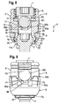
- shows a shows a cross-sectional view of the stabilization device of
Fig. 2 with a second rod in the assembled state, the section being taken perpendicular to the rod axis. - Fig. 9
- shows a side view of the stabilization device of
Fig. 8 . - Fig. 10
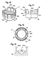
- shows a perspective view of a locking ring of the receiving part of a the stabilization device according to a second embodiment.
- Fig. 11
- shows a side view of the locking ring of
Fig. 10 . - Fig. 12
- shows a top view of the locking ring of
Fig. 10 . - Fig. 13
- shows an cross-sectional view of an enlarged portion of the rod support of the locking ring according a modified second embodiment.
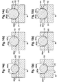
- Fig. 14a) to c)
- show cross-sectional views of an enlarged portion of the rod support of the locking ring according a further modified second embodiment with rods having different diameters.
- Fig. 15a) to c)
- show cross-sectional views of an enlarged portion of the rod support of the locking ring according a still further modified second embodiment with rods having different diameters.
- As shown in
Figs. 1 and 2 , the stabilization device according to a first embodiment includes abone anchoring element 1 in the form of a bone screw having a threaded shaft 2 and ahead 3 with a curved surface portion. In this embodiment the head is spherical segment-shaped. Thehead 3 has a recess 4 for engagement with a tool. The stabilization device also comprises a receivingpart 5 for receiving afirst rod 100 to connect it to thebone anchoring element 1.
Further, a fixation element 7 in the form of an inner screw is provided for fixing therod 100 in the receivingpart 5. The stabilization device includes alocking ring 8 for locking thehead 3 in the receivingpart 5. At least one further rod (not shown) is provided that has a diameter different from the diameter of the first rod. The rods have a circular cross-section. Also, the rods have a substantially smooth surface. - The receiving
part 5 will be explained with reference toFigs. 1 to 4 . It comprises arod receiving portion 9, which is substantially cylindrical and which has afirst end 9a and an oppositesecond end 9b. A coaxialfirst bore 10 is provided at thesecond end 9b as shown inFigs. 3 and8 . The diameter of thefirst bore 10 is smaller than the diameter of thehead 3 of the bone anchoring element. Therod receiving portion 9 further has a coaxialsecond bore 11 extending from thefirst end 9a to a distance from thesecond end 9b. The diameter of thesecond bore 11 is larger than that of thefirst bore 10. A substantiallyU-shaped recess 12 extends from thefirst end 9a in the direction of thesecond end 9b in the rod receiving portion, the diameter of therecess 12 being larger as the diameter of any of the rods so that therod 100 and any other rod of the stabilization device can be placed in the recess and can be guided therein. By means of therecess 12 two free legs are formed on which aninternal thread 13 is provided. The internal thread can be a metric thread, a flat thread, a negative angle thread, a saw-tooth thread, or any other thread form. Preferably, a thread form such as a flat thread or negative angle thread is used, which prevents splaying of thelegs recess 12 is such that therod 100 oreach of the further rods of the stabilization device and the inner screw 7 can be inserted between the legs. - As can be seen in
Fig. 1 , cut-outs 15 are provided in the rod receiving portion on either end of the channel formed by therecess 12. - In the outer surface of the
rod receiving portion 9 agroove 16 is provided, which extends in a circumferential direction and serves for engagement with a portion of thelocking ring 8. - At the side of the
second end 9b the receivingpart 5 comprises ahead receiving portion 17 providing an accommodation space for thehead 3 of thebone anchoring element 1. Thehead receiving portion 17 has a greatest outer diameter, which is smaller than the greatest outer diameter of therod receiving portion 9. An internalhollow section 18 forms a seat for thehead 3 of thebone anchoring element 1 and is open via theopening 19 to thefree end 17b of the head receiving portion. Thehollow section 18 is adapted in its shape to the shape of thehead 3, in the embodiment shown, it is a spherical section to accommodate thespherical head 3. Furthermore, thehollow section 18 is configured to encompass thehead 3 of the bone anchoring element from the side covering a region including the largest diameter of thehead 3. - A plurality of
slits 20 are provided in thehead receiving portion 17, which are open to thefree end 17b. Theslits 20 render thehead receiving portion 17 flexible so that it can be compressed to clamp and finally lock thehead 3 in the hollowinternal portion 18 by means of friction. The number and size ofslits 20 is provided depending on the desired flexibility of thehead receiving portion 17. The flexibility of thehead receiving portion 17 is such that thehead 3 of the anchoring element can be inserted by expanding the head receiving portion and that it can be clamped by compressing the head receiving portion. - The outer surface of the
head receiving portion 17 has afirst section 21, with an outer diameter which increases towardsfree end 17b, for example in an outwardly curved manner. Adjacent to thefirst section 21, there is acircumferential groove 22, which is recessed with respect to thefirst section 21 and which serves for engagement with portion of thelocking ring 8. Adjacent thegroove 22, there is athird portion 23 of the head receiving portion with a substantially cylindrical outer surface. Thethird portion 23 is configured to cooperate with a portion of the locking ring to enhance the clamping effect of the locking ring. - The
locking ring 8 will now be described with reference toFigs. 1 to 7 . Thelocking ring 8 is substantially cylindrical and has anupper end 8a and alower end 8b. In the mounted state theupper end 8a is oriented in the direction of thefirst end 9a of the rod receiving portion and thelower end 8b is oriented towards thefree end 17b of the head receiving portion. As can be seen inFigs. 3 and8 , aninner surface portion 81a is provided near the upper end, which cooperates with the firstouter surface portion 21 of the head receiving portion to exert a compression force onto thehead receiving portion 17. - At the
lower end 8b, the locking ring comprises an inwardly projectingedge 82, the inner diameter of which is smaller than the inner diameter of the other portions of the locking ring. The inwardly projectingedge 82 is configured to engage thegroove 22 of the head receiving portion. - The
locking ring 8 further has upwardly extendingwall portions 83 a, which are separated from each other byslits 84. The upwardly extendingwall portions 83a are arranged at the outer circumference of an innercircumferential shoulder 85 of the locking ring and render the upper portion of the locking ring flexible. The number and size of the slits and the thickness of thewall portions 83a are configured such that a desired flexibility is obtained. At the free end thewall portions 83a compriseengagement sections 83b which are shaped so as to engage thegroove 16 provided on the outer surface of therod receiving portion 9. - The
locking ring 8 is sized in such a way with respect to thehead receiving portion 17 that the head receiving portion can expand within the locking ring to allow the introduction of thehead 3 when the locking ring is a the first position as shown inFig. 3 . - Two
projections 86, which are located diametrically opposite to each other, are formed in the upper portion of the locking ring. Theprojections 86 have such a height that they project above the bottom of the substantiallyU-shaped recess 12 and extend into the cut-outs 15, when thelocking ring 8 is in a position, in which thehead 3 is not yet locked as shown inFigs. 5 . The projections are separated from the upwardly extendingwall portions 83a byslits 84' the size of which is designed such that a distance of thewall portions 83a to the left and right of theprojections 86 is greater than the width of the cut-outs 15 in the receiving part. The locking ring is arranged in such a manner around thehead receiving portion 17 of the receivingpart 5, that theprojections 86 are located at the positions of therecess 12. By means of this, theprojections 86 prevent the locking ring from rotating when the rod is not inserted. - As can be seen in particular in
Figs. 3 to 6 afree end surface 86a of the projections is concave. In the first embodiment thefree end surface 86a is formed as a cylindrical recess with a cylinder radius that is smaller than the radius of thefirst rod 100 and smaller than the radius of any of the further rods. The width of theprojections 86 in the region of thefree end surface 86a is smaller than the diameter of any of the rods that an be inserted. Hence, when thefirst rod 100 is inserted into theU-shaped recess 12 and placed onto theprojections 86, thefirst rod 100 contacts thefree end surface 86a of theprojections 86 at two contact areas P1, P2 that are substantially formed as line contacts extending in the direction of the rod axis R. - The contact areas are located slightly apart from the free edges of the end surfaces 86a towards the bottom of the free end surface.
- When the inner screw 7 is inserted and tightened, it contacts the
rod 100 along a third contact area P3 that is on the top of therod 100. The third contact area P3 is also substantially a line contact, which extends in the direction of the rod axis R. - The flexibility of the
head receiving portion 17 and the size of the head receiving portion at theopen end 17b allows to mount thelocking ring 8 by assembling it from thefree end 17b onto thehead receiving portion 17. - The inner screw 7 has a thread corresponding to the
internal thread 13. If a thread form, which prevents the legs from splaying is used, a single fixation element such as the inner screw 7 is sufficient. This reduces the size of the bone anchoring device in a radial direction. Other fixation elements such as, for example, an outer nut are also possible. - The stabilization device comprises a
second rod 101 which has a diameter that is greater that the diameter of thefirst rod 100 as shown inFigs. 8 and 9 . When thesecond rod 101 is inserted into the receiving part, it rests on the free edges of theend surface 86a of the projections of the locking ring. Hence, the contact areas P1 and P2 are slightly farther apart from each other compared to the contact areas of thefirst rod 100. - The dimensions of the projections and the concave
free end surface 86a and the diameter of the rod as well as the length and shape of the inner screw 7 are such that the rods are clamped along three contact lines P1, P2 and P3. The rod is in a stable position when it is clamped in this way, similar to a three-point fixation. By means of this a secure multi-line contact along the rod is achieved at eachprojection 86. It should be understood that the contact lines are not infinitesimally thin lines, but are lines which have a certain thickness according to the contact that is macroscopically generated. Hence, a safe fixation independently of the diameter of the rod is provided. - The diameter of the rods that can be used with the anchoring device may vary between a largest diameter and a smallest diameter that are defined geometrically in such a way that the rod has in any case two lines of contact with the free end surface of the projections.
- A second embodiment of the stabilization device differs from the first embodiment by the shape of the projections provided on the locking ring. All other portions of the stabilization device are the same and have the same reference numerals. Their description is not repeated. As shown in
Figs. 10 to 12 , thefree end surface 86a' of the projections according to the second embodiment form grooves having a substantially V-shaped cross-section. The bottom of the V can be straight or rounded. An angle α included by the V-shape is such that a rod with a diameter that is smaller than the largest diameter of the V-shaped groove contacts the groove at two opposite contact areas P1, P2 extending in a direction parallel to the rod axis R. As in the first embodiment, the contact areas are substantially line contacts. - As shown in
Fig. 13 , in a modified second embodiment, the bottom of the V-shaped groove has inwardlycurved portions 860a' and straight sidewalls 861a'. - In a further modification, as shown in
Figs. 14a ) to c) the V-shaped groove has additionallystraight side walls 863a'. - In a still further modification as shown in
Figs. 15a) to 15c) the V-shaped groove has concavely curved sidewalls 864a' of the V and straight sidewalls 863a'. Also in the modified embodiments the rod rests on thefree end surface 86a' along two contact areas P1, P2. -
Figs. 14a) to 14c) and Figs. 15a) to 15c) show schematically the contact ofrods - The receiving
part 5, thelocking ring 8, the inner screw 7 and thebone anchoring element 1 are made of a bio-compatible material, for example of titanium or stainless steel or a bio-compatible alloy such as Nitinol or a bio-compatible plastic material, such as PEEK. Parts can all be made of the same or of different materials. - The function of the locking ring that is the same for all embodiments will now be explained with referenced
Figs. 3 and8 . As shown inFig. 3 and8 , a first position of the locking 8, which is the insertion position and in which thelocking ring 8 is latched with respect to the receivingpart 5, is defined in such a way that the inwardly projectingedge 82 engagesgroove 22 at the outer surface of thehead receiving portion 17. The inner diameter of the inwardly projectingedge 82 is larger than the outer diameter of thehead receiving portion 17 at the position of thegroove 22, so as to allow an expansion of thehead receiving portion 17, when thehead 3 is introduced. In the first position, thelocking ring 8 is additionally held by a clamping force between therod receiving portion 9 of the receivingpart 5 and theflexible wall portions 83a of the locking ring which are slightly bent outwards. - When the locking ring is in the first position, the
head receiving portion 17 is not compressed. In this position, the introduction of the screw head is possible. In the first position, the locking ring is prevented from moving upwards towards thefirst end 9a of the rod receiving portion, since it abuts with theshoulder 85 against thesecond end 9b of the head receiving portion and with the inwardly projectingedge 82 against the upper wall 16b ofgroove 16. The abutment of the locking ring against thesecond end 9b and against the upper wall ofgroove 16 holds thelocking ring 8 in place against upward movement. Since the inner diameter of the locking ring is larger than the outer diameter of the head receiving portion in a non-compressed state, an expansion of thehead receiving portion 17 into the space within the locking ring is possible. In the first position, the head can freely pivot. - A second position (not shown), in which the locking ring is latched with respect to the receiving
part 5 and which is the pre-locking position is achieved by shifting thelocking ring 8 as indicated by the arrow A towards thefree end 17b of the head receiving portion until theengagement portions 83b of theflexible wall portions 83a resiliently snap into thegroove 16 provided at therod receiving portion 9. - In the second position the inner
inclined surface 81 a of the locking ring presses against the firstouter surface portion 21 of the head receiving portion so as to compress thehead receiving portion 17 to clamp thehead 3 within the hollowinternal portion 18 without fully locking the head. In addition, the inwardly projectingedge 82 presses against thethird portion 23 of thehead receiving portion 17 resulting in an additional clamping force. Thereby, clamping of the head can be effected not only from above or the side of thehead 3 but also from a region of the lower portion ofhead 3. Under conditions arising during surgery, the angular position of thebone anchoring element 1 with respect to the receivingpart 5 is maintained and can be loosened only by exerting an additional force onto the receiving part of the screw element. In this pre-locked position the bone anchoring element cannot be removed from the receiving part but angulation of the screw element is possible. - A third position (not shown), which is the locking position, is achieved by shifting the locking ring further downwards until the
screw head 3 is finally locked within thehead receiving portion 17. Theinner surface 81a of the locking ring engages the outer surface of thefirst portion 21 of thehead receiving portion 17 in such a way that thehead 3 is locked by compression of the head receiving portion. In addition, the inwardly projectingedge 82 further compresses the head receiving portion at thelower portion 23, thereby enhancing the locking force. - The bone anchoring device is preassembled as follows. First, the
locking ring 8 is mounted onto the receivingpart 5 from thefree end 17b. This can be done, for example, by the manufacturer. Preferably, thelocking ring 8 is in the first position shown inFigs. 3 an 8 in which it is latched by engagement of the inwardly projectingedge 82 with thegroove 22. Thereafter, thehead 3 of theanchoring element 1 is introduced from thefree end 17b into the hollowinternal portion 18 of thehead receiving portion 17. Thereafter, the locking ring is moved relative to the receiving part downwards, so that the inwardly projectingring 82 slides out of thegroove 22 and theengagement portions 83b of theflexible wall portions 83a snap intogroove 16, whereby the second position. - In use during surgery, the preassembled bone anchoring device comprising the receiving part, the bone anchoring element and the locking ring in the pre-locking position, is screwed into the bone. The recess 4 of the head can be accessed with a screw tool through the
first bore 10. - A rod is selected that has a diameter suitable for the specific clinical application and inserted into the
recess 12 until it is supported by the free end surface of theprojections 86. Hence, with the stabilization device a modular system is provided that allows to select and assemble a suitable anchoring element and a suitable rod. - To correctly align the receiving part with respect to the rod, the receiving part is pivoted. Once the correct position of the rod with respect to other bone anchoring devices is achieved, the inner screw 7 is tightened. Since the rod 6 abuts onto the
projections 86 of the locking ring, thelocking ring 8 is shifted downward into the third position which is the locking position. When thelocking ring 8 is moved towards thefree end 17b of the head receiving portion, it compresses the head receiving portion, thereby locking the head. Final tightening of the inner screw locks the rod and the head simultaneously. - Further modifications of the embodiment shown are possible. For example, the locking ring can have another shape. The pre-locking function can be realized otherwise.
- For the anchoring element, all kinds of known anchoring elements such as screws, nails, hooks, cannulated screws, anchoring elements with separated head and shaft that can be connected to each other can be used.
- The rods may also have a curvature along the rod axis.
- The head receiving portion can have an inclined open end or can be otherwise asymmetric to allow a greater angulation of the head in one direction.
- The outer surface of the head receiving portion and the inner surface of the locking ring can have other shapes which allow a compression of the head receiving portion when the locking ring is shifted downwards.
Claims (11)
- Stabilization device for stabilizing vertebrae or other bones including at least two rods (100, 101) having a different diameter;
an anchoring element (1) having a shaft (2) for anchoring in the bone and a head (3);
a receiving part (5) for connecting one rod from the at least two rods to the anchoring element;
the receiving part comprising
a top end (9a) and a bottom end (17b);
a rod receiving portion (9) with a channel (12) for receiving the rod (6), and
a head receiving portion (17) for accommodating a head (3) of the bone anchoring element, the head receiving portion having an open end (19, 17b) and being flexible so as to allow introduction and clamping of the head; and
a locking ring (8) embracing the head receiving portion (17), wherein the head is clamped by pressing onto the locking ring with the rod to move the locking ring towards the open end (17b);
wherein the locking ring (8) has a surface portion (86a, 86a') configured to contact each of the rods (100, 101) in a circumferential direction at at least two distinct contact areas (P1, P2). - The stabilization device of claim 1, wherein the surface portion is shaped such that the contact areas (P1, P2) extend along the rod axis (R).
- The stabilization device of claim 1 or 2, wherein the surface portion (86a) is curved with a radius of curvature that is smaller than a radius of curvature of each of the rods (100, 101).
- The stabilization device of one of claims 1 to 3, wherein the surface portion (86a) is formed through a cylindrical recess with a diameter smaller than the diameter of any of the rods (100, 101).
- The stabilization device of one of claims 1 to 3, wherein the surface portion (86a') is substantially V-shaped.
- The stabilization device of claim 5, wherein the side walls (860a',864a')of the base which form the V-shape are curved.
- The stabilization device of claim 5 or 6, wherein the surface portion further includes straight sidewalls (863a').
- The stabilization device of one of claims 1 to 7, wherein the surface portion is shaped such as to clamp a plurality of rods with different diameters in a stepless manner.
- The stabilization device of one of claims 1 to 8, wherein the rod has a substantially circular cross section.
- The stabilization device of one of claims 1 to 9, wherein the locking ring has two projections (86) that are offset by 180° from each other and wherein each of the projections comprises the surface portion configured to contact each of the rods in a circumferential direction at at least two distinct contact areas.
- The stabilization device of claim 10, wherein the projections (86) extend into the channel (12).
Priority Applications (7)
| Application Number | Priority Date | Filing Date | Title |
|---|---|---|---|
| ES10196866T ES2399983T3 (en) | 2010-12-23 | 2010-12-23 | Stabilization device for vertebrae or bone parts |
| EP10196866A EP2468197B1 (en) | 2010-12-23 | 2010-12-23 | Stabilization device for stabilizing vertebrae or bone parts |
| CN201110428661.0A CN102525621B (en) | 2010-12-23 | 2011-12-20 | Stabilization device for stabilizing vertebrae or bone parts |
| KR1020110138378A KR20120072321A (en) | 2010-12-23 | 2011-12-20 | Stabilization device for stabilizing vertebrae or bone parts |
| JP2011278131A JP6186109B2 (en) | 2010-12-23 | 2011-12-20 | Stabilization device for stabilizing vertebrae or other bones |
| TW100147234A TW201225902A (en) | 2010-12-23 | 2011-12-20 | Stabilization device for stabilizing vertebrae or bone parts |
| US13/336,693 US8764805B2 (en) | 2010-12-23 | 2011-12-23 | Stabilization device for stabilizing vertebrae or bone parts |
Applications Claiming Priority (1)
| Application Number | Priority Date | Filing Date | Title |
|---|---|---|---|
| EP10196866A EP2468197B1 (en) | 2010-12-23 | 2010-12-23 | Stabilization device for stabilizing vertebrae or bone parts |
Publications (2)
| Publication Number | Publication Date |
|---|---|
| EP2468197A1 true EP2468197A1 (en) | 2012-06-27 |
| EP2468197B1 EP2468197B1 (en) | 2012-11-21 |
Family
ID=43743460
Family Applications (1)
| Application Number | Title | Priority Date | Filing Date |
|---|---|---|---|
| EP10196866A Active EP2468197B1 (en) | 2010-12-23 | 2010-12-23 | Stabilization device for stabilizing vertebrae or bone parts |
Country Status (7)
| Country | Link |
|---|---|
| US (1) | US8764805B2 (en) |
| EP (1) | EP2468197B1 (en) |
| JP (1) | JP6186109B2 (en) |
| KR (1) | KR20120072321A (en) |
| CN (1) | CN102525621B (en) |
| ES (1) | ES2399983T3 (en) |
| TW (1) | TW201225902A (en) |
Cited By (1)
| Publication number | Priority date | Publication date | Assignee | Title |
|---|---|---|---|---|
| EP3695796A1 (en) * | 2019-02-13 | 2020-08-19 | Biedermann Technologies GmbH & Co. KG | Anchoring assembly for anchoring a rod to a bone or a vertebra |
Families Citing this family (23)
| Publication number | Priority date | Publication date | Assignee | Title |
|---|---|---|---|---|
| DE602007007758D1 (en) | 2007-07-31 | 2010-08-26 | Biedermann Motech Gmbh | Bone anchoring device |
| WO2011106339A1 (en) * | 2010-02-23 | 2011-09-01 | K2M, Inc. | Polyaxial bone screw assembly |
| ES2394774T3 (en) * | 2010-05-05 | 2013-02-05 | Biedermann Technologies Gmbh & Co. Kg | Receiver piece intended to receive a bar for coupling with an anchoring element for bone, anchoring device for bone and method and tool for mounting it |
| US8414623B2 (en) * | 2010-10-29 | 2013-04-09 | Warsaw Orthopedic, Inc. | Connector for connecting elongated members |
| ES2473915T3 (en) * | 2010-12-10 | 2014-07-08 | Biedermann Technologies Gmbh & Co. Kg | Receiver piece for receiving and housing a bar in order to couple it to a bone anchoring element and bone anchoring device with said receiving piece |
| EP2462888B1 (en) * | 2010-12-10 | 2015-02-18 | Biedermann Technologies GmbH & Co. KG | Receiving part for receiving a rod for coupling the rod to a bone anchoring element and bone anchoring device with such a receiving part |
| EP2918237A1 (en) * | 2011-09-15 | 2015-09-16 | Biedermann Technologies GmbH & Co. KG | Polyaxial bone anchoring device with enlarged pivot angle |
| US9358046B2 (en) * | 2012-12-31 | 2016-06-07 | Globus Medical, Inc. | Rod coupling system and devices and methods of making and using the same |
| EP2764840B1 (en) | 2013-02-11 | 2017-05-03 | Biedermann Technologies GmbH & Co. KG | Coupling assembly for coupling a rod to a bone anchoring element and bone anchoring device with such a coupling assembly |
| US20140277159A1 (en) * | 2013-03-14 | 2014-09-18 | DePuy Synthes Products, LLC | Bottom-loading bone anchor assemblies |
| EP3023064B1 (en) | 2014-11-20 | 2019-01-09 | Biedermann Technologies GmbH & Co. KG | Receiving part for coupling a bone anchor to a rod and bone anchoring device with such a receiving part |
| US9707013B2 (en) * | 2015-04-30 | 2017-07-18 | Warsaw Orthopedic, Inc. | Spinal implant system and methods of use |
| CN104825221B (en) * | 2015-05-14 | 2018-01-16 | 林健泽 | A kind of Improvement type pedicle screw |
| US10568667B2 (en) | 2016-07-13 | 2020-02-25 | Medos International Sàrl | Bone anchor assemblies and related instrumentation |
| US10363073B2 (en) | 2016-07-13 | 2019-07-30 | Medos International Sàrl | Bone anchor assemblies and related instrumentation |
| US10874438B2 (en) | 2016-07-13 | 2020-12-29 | Medos International Sarl | Bone anchor assemblies and related instrumentation |
| US10463402B2 (en) | 2016-07-13 | 2019-11-05 | Medos International Sàrl | Bone anchor assemblies and related instrumentation |
| EP3437576B1 (en) * | 2017-08-03 | 2022-02-09 | Biedermann Technologies GmbH & Co. KG | Stabilization device for bones or vertebrae |
| US11571244B2 (en) | 2019-05-22 | 2023-02-07 | Nuvasive, Inc. | Posterior spinal fixation screws |
| CN110478019B (en) * | 2019-08-20 | 2024-02-20 | 董谢平 | A hoop-type split dynamic and static pedicle screw |
| EP3838196B1 (en) * | 2019-12-18 | 2024-01-31 | Biedermann Technologies GmbH & Co. KG | Coupling device and instrument for placing a coupling device to a head of a bone anchor |
| EP4074271B1 (en) * | 2021-04-15 | 2024-09-11 | Biedermann Technologies GmbH & Co. KG | Polyaxial bone anchoring device |
| EP4129220B1 (en) * | 2021-08-04 | 2024-07-03 | Biedermann Technologies GmbH & Co. KG | Coupling device for coupling a rod to a bone anchoring element and method of manufacturing the same |
Citations (5)
| Publication number | Priority date | Publication date | Assignee | Title |
|---|---|---|---|---|
| DE4110002C1 (en) * | 1991-03-27 | 1992-05-21 | Heinrich 7900 Ulm De Ulrich | Vertebral column correcting and stabilising implant - has screw head retainer wall with two parallel, protruding edges pointing against threaded rod |
| US5873878A (en) | 1996-04-30 | 1999-02-23 | Harms; Juergen | Anchoring member |
| DE19912364A1 (en) * | 1999-03-19 | 2000-10-12 | Peter Brehm | Screw to fix reinforcement rod along spinal column; has U-shaped recess for reinforcement rod with saw-tooth thread having surfaces at negative angle to secure fixing screw |
| EP2070485A1 (en) | 2007-12-13 | 2009-06-17 | Biedermann Motech GmbH | Anchoring device for anchoring a rod in bones or vertebrae |
| EP2201903A1 (en) * | 2008-12-29 | 2010-06-30 | Biedermann Motech GmbH | Receiving part for receiving a rod for coupling the rod to a bone anchoring element and bone anchoring device with such a receiving part |
Family Cites Families (7)
| Publication number | Priority date | Publication date | Assignee | Title |
|---|---|---|---|---|
| US6077262A (en) | 1993-06-04 | 2000-06-20 | Synthes (U.S.A.) | Posterior spinal implant |
| FR2859376B1 (en) * | 2003-09-04 | 2006-05-19 | Spine Next Sa | SPINAL IMPLANT |
| US7678139B2 (en) | 2004-04-20 | 2010-03-16 | Allez Spine, Llc | Pedicle screw assembly |
| US7857834B2 (en) | 2004-06-14 | 2010-12-28 | Zimmer Spine, Inc. | Spinal implant fixation assembly |
| DE602005008752D1 (en) * | 2005-11-17 | 2008-09-18 | Biedermann Motech Gmbh | Polyaxial screw for flexible rod |
| US7967848B2 (en) * | 2008-01-16 | 2011-06-28 | Custom Spine, Inc. | Spring-loaded dynamic pedicle screw assembly |
| EP2105101B2 (en) * | 2008-03-28 | 2013-09-11 | BIEDERMANN MOTECH GmbH | Bone anchoring device |
-
2010
- 2010-12-23 EP EP10196866A patent/EP2468197B1/en active Active
- 2010-12-23 ES ES10196866T patent/ES2399983T3/en active Active
-
2011
- 2011-12-20 JP JP2011278131A patent/JP6186109B2/en not_active Expired - Fee Related
- 2011-12-20 KR KR1020110138378A patent/KR20120072321A/en not_active Withdrawn
- 2011-12-20 CN CN201110428661.0A patent/CN102525621B/en not_active Expired - Fee Related
- 2011-12-20 TW TW100147234A patent/TW201225902A/en unknown
- 2011-12-23 US US13/336,693 patent/US8764805B2/en not_active Expired - Fee Related
Patent Citations (5)
| Publication number | Priority date | Publication date | Assignee | Title |
|---|---|---|---|---|
| DE4110002C1 (en) * | 1991-03-27 | 1992-05-21 | Heinrich 7900 Ulm De Ulrich | Vertebral column correcting and stabilising implant - has screw head retainer wall with two parallel, protruding edges pointing against threaded rod |
| US5873878A (en) | 1996-04-30 | 1999-02-23 | Harms; Juergen | Anchoring member |
| DE19912364A1 (en) * | 1999-03-19 | 2000-10-12 | Peter Brehm | Screw to fix reinforcement rod along spinal column; has U-shaped recess for reinforcement rod with saw-tooth thread having surfaces at negative angle to secure fixing screw |
| EP2070485A1 (en) | 2007-12-13 | 2009-06-17 | Biedermann Motech GmbH | Anchoring device for anchoring a rod in bones or vertebrae |
| EP2201903A1 (en) * | 2008-12-29 | 2010-06-30 | Biedermann Motech GmbH | Receiving part for receiving a rod for coupling the rod to a bone anchoring element and bone anchoring device with such a receiving part |
Cited By (3)
| Publication number | Priority date | Publication date | Assignee | Title |
|---|---|---|---|---|
| EP3695796A1 (en) * | 2019-02-13 | 2020-08-19 | Biedermann Technologies GmbH & Co. KG | Anchoring assembly for anchoring a rod to a bone or a vertebra |
| US11166753B2 (en) | 2019-02-13 | 2021-11-09 | Biedermann Technologies Gmbh & Co. Kg | Anchoring assembly for anchoring a rod to a bone or a vertebra |
| US12232775B2 (en) | 2019-02-13 | 2025-02-25 | Biedermann Technologies Gmbh & Co. Kg | Anchoring assembly for anchoring a rod to a bone or a vertebra |
Also Published As
| Publication number | Publication date |
|---|---|
| JP2012130696A (en) | 2012-07-12 |
| ES2399983T3 (en) | 2013-04-04 |
| US8764805B2 (en) | 2014-07-01 |
| US20120165874A1 (en) | 2012-06-28 |
| EP2468197B1 (en) | 2012-11-21 |
| JP6186109B2 (en) | 2017-08-23 |
| CN102525621A (en) | 2012-07-04 |
| CN102525621B (en) | 2015-07-22 |
| TW201225902A (en) | 2012-07-01 |
| KR20120072321A (en) | 2012-07-03 |
Similar Documents
| Publication | Publication Date | Title |
|---|---|---|
| EP2468197B1 (en) | Stabilization device for stabilizing vertebrae or bone parts | |
| US9289246B2 (en) | Bone anchoring device | |
| EP2689734B1 (en) | Polyaxial bone anchoring device with enlarged pivot angle | |
| EP2591740B1 (en) | Polyaxial bone anchoring device | |
| EP2384710B1 (en) | Method and tool for assembling a bone anchoring device | |
| EP2570090B1 (en) | Polyaxial bone anchoring device with enlarged pivot angle | |
| EP2204129B1 (en) | Receiving part for receiving a rod for coupling the rod to a bone anchoring element and a bone anchoring device with such a receiving part | |
| EP2526881B1 (en) | Receiving part for receiving a rod for coupling the rod to a bone anchoring element and bone anchoring device with such a receiving part | |
| EP2514378B1 (en) | Bone anchoring device | |
| EP3158957B1 (en) | Coupling device for coupling a bone anchor to a rod and bone anchoring device with such a coupling device | |
| EP2604204B1 (en) | Monoplanar bone anchoring device with selectable pivot plane | |
| EP2070485A1 (en) | Anchoring device for anchoring a rod in bones or vertebrae | |
| EP2851021A1 (en) | Coupling assembly for coupling a rod to a bone anchoring element, polyaxial bone anchoring device and modular stabilization device | |
| EP3476340A1 (en) | Polyaxial bone anchoring device | |
| EP3437576A1 (en) | Stabilization device for bones or vertebrae | |
| EP3900654B1 (en) | Bone anchoring device | |
| KR20160145497A (en) | Receiving part of a bone anchoring device and bone anchoring device with such a receiving part |
Legal Events
| Date | Code | Title | Description |
|---|---|---|---|
| 17P | Request for examination filed |
Effective date: 20111004 |
|
| AK | Designated contracting states |
Kind code of ref document: A1 Designated state(s): AL AT BE BG CH CY CZ DE DK EE ES FI FR GB GR HR HU IE IS IT LI LT LU LV MC MK MT NL NO PL PT RO RS SE SI SK SM TR |
|
| AX | Request for extension of the european patent |
Extension state: BA ME |
|
| PUAI | Public reference made under article 153(3) epc to a published international application that has entered the european phase |
Free format text: ORIGINAL CODE: 0009012 |
|
| GRAP | Despatch of communication of intention to grant a patent |
Free format text: ORIGINAL CODE: EPIDOSNIGR1 |
|
| GRAS | Grant fee paid |
Free format text: ORIGINAL CODE: EPIDOSNIGR3 |
|
| GRAA | (expected) grant |
Free format text: ORIGINAL CODE: 0009210 |
|
| AK | Designated contracting states |
Kind code of ref document: B1 Designated state(s): AL AT BE BG CH CY CZ DE DK EE ES FI FR GB GR HR HU IE IS IT LI LT LU LV MC MK MT NL NO PL PT RO RS SE SI SK SM TR |
|
| REG | Reference to a national code |
Ref country code: GB Ref legal event code: FG4D |
|
| REG | Reference to a national code |
Ref country code: CH Ref legal event code: EP Ref country code: CH Ref legal event code: NV Representative=s name: NOVAGRAAF INTERNATIONAL SA, CH |
|
| REG | Reference to a national code |
Ref country code: AT Ref legal event code: REF Ref document number: 584636 Country of ref document: AT Kind code of ref document: T Effective date: 20121215 |
|
| REG | Reference to a national code |
Ref country code: IE Ref legal event code: FG4D |
|
| REG | Reference to a national code |
Ref country code: DE Ref legal event code: R096 Ref document number: 602010003718 Country of ref document: DE Effective date: 20130117 |
|
| REG | Reference to a national code |
Ref country code: ES Ref legal event code: FG2A Ref document number: 2399983 Country of ref document: ES Kind code of ref document: T3 Effective date: 20130404 |
|
| REG | Reference to a national code |
Ref country code: NL Ref legal event code: VDEP Effective date: 20121121 |
|
| REG | Reference to a national code |
Ref country code: AT Ref legal event code: MK05 Ref document number: 584636 Country of ref document: AT Kind code of ref document: T Effective date: 20121121 |
|
| REG | Reference to a national code |
Ref country code: LT Ref legal event code: MG4D |
|
| PG25 | Lapsed in a contracting state [announced via postgrant information from national office to epo] |
Ref country code: LT Free format text: LAPSE BECAUSE OF FAILURE TO SUBMIT A TRANSLATION OF THE DESCRIPTION OR TO PAY THE FEE WITHIN THE PRESCRIBED TIME-LIMIT Effective date: 20121121 Ref country code: SE Free format text: LAPSE BECAUSE OF FAILURE TO SUBMIT A TRANSLATION OF THE DESCRIPTION OR TO PAY THE FEE WITHIN THE PRESCRIBED TIME-LIMIT Effective date: 20121121 Ref country code: FI Free format text: LAPSE BECAUSE OF FAILURE TO SUBMIT A TRANSLATION OF THE DESCRIPTION OR TO PAY THE FEE WITHIN THE PRESCRIBED TIME-LIMIT Effective date: 20121121 Ref country code: NO Free format text: LAPSE BECAUSE OF FAILURE TO SUBMIT A TRANSLATION OF THE DESCRIPTION OR TO PAY THE FEE WITHIN THE PRESCRIBED TIME-LIMIT Effective date: 20130221 |
|
| PG25 | Lapsed in a contracting state [announced via postgrant information from national office to epo] |
Ref country code: SI Free format text: LAPSE BECAUSE OF FAILURE TO SUBMIT A TRANSLATION OF THE DESCRIPTION OR TO PAY THE FEE WITHIN THE PRESCRIBED TIME-LIMIT Effective date: 20121121 Ref country code: GR Free format text: LAPSE BECAUSE OF FAILURE TO SUBMIT A TRANSLATION OF THE DESCRIPTION OR TO PAY THE FEE WITHIN THE PRESCRIBED TIME-LIMIT Effective date: 20130222 Ref country code: BE Free format text: LAPSE BECAUSE OF FAILURE TO SUBMIT A TRANSLATION OF THE DESCRIPTION OR TO PAY THE FEE WITHIN THE PRESCRIBED TIME-LIMIT Effective date: 20121121 Ref country code: LV Free format text: LAPSE BECAUSE OF FAILURE TO SUBMIT A TRANSLATION OF THE DESCRIPTION OR TO PAY THE FEE WITHIN THE PRESCRIBED TIME-LIMIT Effective date: 20121121 Ref country code: PT Free format text: LAPSE BECAUSE OF FAILURE TO SUBMIT A TRANSLATION OF THE DESCRIPTION OR TO PAY THE FEE WITHIN THE PRESCRIBED TIME-LIMIT Effective date: 20130321 Ref country code: PL Free format text: LAPSE BECAUSE OF FAILURE TO SUBMIT A TRANSLATION OF THE DESCRIPTION OR TO PAY THE FEE WITHIN THE PRESCRIBED TIME-LIMIT Effective date: 20121121 |
|
| PG25 | Lapsed in a contracting state [announced via postgrant information from national office to epo] |
Ref country code: AT Free format text: LAPSE BECAUSE OF FAILURE TO SUBMIT A TRANSLATION OF THE DESCRIPTION OR TO PAY THE FEE WITHIN THE PRESCRIBED TIME-LIMIT Effective date: 20121121 |
|
| PG25 | Lapsed in a contracting state [announced via postgrant information from national office to epo] |
Ref country code: SK Free format text: LAPSE BECAUSE OF FAILURE TO SUBMIT A TRANSLATION OF THE DESCRIPTION OR TO PAY THE FEE WITHIN THE PRESCRIBED TIME-LIMIT Effective date: 20121121 Ref country code: CZ Free format text: LAPSE BECAUSE OF FAILURE TO SUBMIT A TRANSLATION OF THE DESCRIPTION OR TO PAY THE FEE WITHIN THE PRESCRIBED TIME-LIMIT Effective date: 20121121 Ref country code: BG Free format text: LAPSE BECAUSE OF FAILURE TO SUBMIT A TRANSLATION OF THE DESCRIPTION OR TO PAY THE FEE WITHIN THE PRESCRIBED TIME-LIMIT Effective date: 20130221 Ref country code: EE Free format text: LAPSE BECAUSE OF FAILURE TO SUBMIT A TRANSLATION OF THE DESCRIPTION OR TO PAY THE FEE WITHIN THE PRESCRIBED TIME-LIMIT Effective date: 20121121 Ref country code: RS Free format text: LAPSE BECAUSE OF FAILURE TO SUBMIT A TRANSLATION OF THE DESCRIPTION OR TO PAY THE FEE WITHIN THE PRESCRIBED TIME-LIMIT Effective date: 20121121 Ref country code: MC Free format text: LAPSE BECAUSE OF NON-PAYMENT OF DUE FEES Effective date: 20121231 Ref country code: DK Free format text: LAPSE BECAUSE OF FAILURE TO SUBMIT A TRANSLATION OF THE DESCRIPTION OR TO PAY THE FEE WITHIN THE PRESCRIBED TIME-LIMIT Effective date: 20121121 |
|
| PG25 | Lapsed in a contracting state [announced via postgrant information from national office to epo] |
Ref country code: RO Free format text: LAPSE BECAUSE OF FAILURE TO SUBMIT A TRANSLATION OF THE DESCRIPTION OR TO PAY THE FEE WITHIN THE PRESCRIBED TIME-LIMIT Effective date: 20121121 Ref country code: NL Free format text: LAPSE BECAUSE OF FAILURE TO SUBMIT A TRANSLATION OF THE DESCRIPTION OR TO PAY THE FEE WITHIN THE PRESCRIBED TIME-LIMIT Effective date: 20121121 |
|
| REG | Reference to a national code |
Ref country code: IE Ref legal event code: MM4A |
|
| PLBE | No opposition filed within time limit |
Free format text: ORIGINAL CODE: 0009261 |
|
| STAA | Information on the status of an ep patent application or granted ep patent |
Free format text: STATUS: NO OPPOSITION FILED WITHIN TIME LIMIT |
|
| 26N | No opposition filed |
Effective date: 20130822 |
|
| PG25 | Lapsed in a contracting state [announced via postgrant information from national office to epo] |
Ref country code: IE Free format text: LAPSE BECAUSE OF NON-PAYMENT OF DUE FEES Effective date: 20121223 |
|
| PG25 | Lapsed in a contracting state [announced via postgrant information from national office to epo] |
Ref country code: AL Free format text: LAPSE BECAUSE OF FAILURE TO SUBMIT A TRANSLATION OF THE DESCRIPTION OR TO PAY THE FEE WITHIN THE PRESCRIBED TIME-LIMIT Effective date: 20121121 Ref country code: MT Free format text: LAPSE BECAUSE OF FAILURE TO SUBMIT A TRANSLATION OF THE DESCRIPTION OR TO PAY THE FEE WITHIN THE PRESCRIBED TIME-LIMIT Effective date: 20121121 |
|
| REG | Reference to a national code |
Ref country code: DE Ref legal event code: R097 Ref document number: 602010003718 Country of ref document: DE Effective date: 20130822 |
|
| PG25 | Lapsed in a contracting state [announced via postgrant information from national office to epo] |
Ref country code: HR Free format text: LAPSE BECAUSE OF FAILURE TO SUBMIT A TRANSLATION OF THE DESCRIPTION OR TO PAY THE FEE WITHIN THE PRESCRIBED TIME-LIMIT Effective date: 20130731 |
|
| PG25 | Lapsed in a contracting state [announced via postgrant information from national office to epo] |
Ref country code: TR Free format text: LAPSE BECAUSE OF FAILURE TO SUBMIT A TRANSLATION OF THE DESCRIPTION OR TO PAY THE FEE WITHIN THE PRESCRIBED TIME-LIMIT Effective date: 20121121 |
|
| PG25 | Lapsed in a contracting state [announced via postgrant information from national office to epo] |
Ref country code: CY Free format text: LAPSE BECAUSE OF FAILURE TO SUBMIT A TRANSLATION OF THE DESCRIPTION OR TO PAY THE FEE WITHIN THE PRESCRIBED TIME-LIMIT Effective date: 20121121 Ref country code: LU Free format text: LAPSE BECAUSE OF NON-PAYMENT OF DUE FEES Effective date: 20121223 Ref country code: SM Free format text: LAPSE BECAUSE OF FAILURE TO SUBMIT A TRANSLATION OF THE DESCRIPTION OR TO PAY THE FEE WITHIN THE PRESCRIBED TIME-LIMIT Effective date: 20121121 |
|
| PG25 | Lapsed in a contracting state [announced via postgrant information from national office to epo] |
Ref country code: HU Free format text: LAPSE BECAUSE OF FAILURE TO SUBMIT A TRANSLATION OF THE DESCRIPTION OR TO PAY THE FEE WITHIN THE PRESCRIBED TIME-LIMIT Effective date: 20101223 |
|
| PG25 | Lapsed in a contracting state [announced via postgrant information from national office to epo] |
Ref country code: MK Free format text: LAPSE BECAUSE OF FAILURE TO SUBMIT A TRANSLATION OF THE DESCRIPTION OR TO PAY THE FEE WITHIN THE PRESCRIBED TIME-LIMIT Effective date: 20121121 |
|
| REG | Reference to a national code |
Ref country code: FR Ref legal event code: PLFP Year of fee payment: 6 |
|
| PG25 | Lapsed in a contracting state [announced via postgrant information from national office to epo] |
Ref country code: IS Free format text: LAPSE BECAUSE OF FAILURE TO SUBMIT A TRANSLATION OF THE DESCRIPTION OR TO PAY THE FEE WITHIN THE PRESCRIBED TIME-LIMIT Effective date: 20121121 |
|
| REG | Reference to a national code |
Ref country code: FR Ref legal event code: PLFP Year of fee payment: 7 |
|
| PGFP | Annual fee paid to national office [announced via postgrant information from national office to epo] |
Ref country code: FR Payment date: 20161221 Year of fee payment: 7 Ref country code: ES Payment date: 20161221 Year of fee payment: 7 |
|
| PGFP | Annual fee paid to national office [announced via postgrant information from national office to epo] |
Ref country code: IT Payment date: 20161229 Year of fee payment: 7 |
|
| REG | Reference to a national code |
Ref country code: FR Ref legal event code: ST Effective date: 20180831 |
|
| PG25 | Lapsed in a contracting state [announced via postgrant information from national office to epo] |
Ref country code: IT Free format text: LAPSE BECAUSE OF NON-PAYMENT OF DUE FEES Effective date: 20171223 Ref country code: FR Free format text: LAPSE BECAUSE OF NON-PAYMENT OF DUE FEES Effective date: 20180102 |
|
| REG | Reference to a national code |
Ref country code: ES Ref legal event code: FD2A Effective date: 20190703 |
|
| PG25 | Lapsed in a contracting state [announced via postgrant information from national office to epo] |
Ref country code: ES Free format text: LAPSE BECAUSE OF NON-PAYMENT OF DUE FEES Effective date: 20171224 |
|
| P01 | Opt-out of the competence of the unified patent court (upc) registered |
Effective date: 20230525 |
|
| REG | Reference to a national code |
Ref country code: CH Ref legal event code: U11 Free format text: ST27 STATUS EVENT CODE: U-0-0-U10-U11 (AS PROVIDED BY THE NATIONAL OFFICE) Effective date: 20260101 |
|
| PGFP | Annual fee paid to national office [announced via postgrant information from national office to epo] |
Ref country code: GB Payment date: 20251210 Year of fee payment: 16 |
|
| PGFP | Annual fee paid to national office [announced via postgrant information from national office to epo] |
Ref country code: DE Payment date: 20251219 Year of fee payment: 16 |
|
| PGFP | Annual fee paid to national office [announced via postgrant information from national office to epo] |
Ref country code: CH Payment date: 20260101 Year of fee payment: 16 |