EP2467915B1 - Support towers, insulating cross-arms and insulating members for high voltage power networks - Google Patents
Support towers, insulating cross-arms and insulating members for high voltage power networks Download PDFInfo
- Publication number
- EP2467915B1 EP2467915B1 EP10766081.3A EP10766081A EP2467915B1 EP 2467915 B1 EP2467915 B1 EP 2467915B1 EP 10766081 A EP10766081 A EP 10766081A EP 2467915 B1 EP2467915 B1 EP 2467915B1
- Authority
- EP
- European Patent Office
- Prior art keywords
- cross
- insulating
- sectional profile
- arm
- members
- Prior art date
- Legal status (The legal status is an assumption and is not a legal conclusion. Google has not performed a legal analysis and makes no representation as to the accuracy of the status listed.)
- Active
Links
Images





Classifications
-
- H—ELECTRICITY
- H02—GENERATION; CONVERSION OR DISTRIBUTION OF ELECTRIC POWER
- H02G—INSTALLATION OF ELECTRIC CABLES OR LINES, OR OF COMBINED OPTICAL AND ELECTRIC CABLES OR LINES
- H02G7/00—Overhead installations of electric lines or cables
- H02G7/05—Suspension arrangements or devices for electric cables or lines
- H02G7/053—Suspension clamps and clips for electric overhead lines not suspended to a supporting wire
-
- H—ELECTRICITY
- H01—ELECTRIC ELEMENTS
- H01B—CABLES; CONDUCTORS; INSULATORS; SELECTION OF MATERIALS FOR THEIR CONDUCTIVE, INSULATING OR DIELECTRIC PROPERTIES
- H01B17/00—Insulators or insulating bodies characterised by their form
- H01B17/02—Suspension insulators; Strain insulators
- H01B17/12—Special features of strain insulators
-
- H—ELECTRICITY
- H01—ELECTRIC ELEMENTS
- H01B—CABLES; CONDUCTORS; INSULATORS; SELECTION OF MATERIALS FOR THEIR CONDUCTIVE, INSULATING OR DIELECTRIC PROPERTIES
- H01B17/00—Insulators or insulating bodies characterised by their form
- H01B17/14—Supporting insulators
-
- H—ELECTRICITY
- H02—GENERATION; CONVERSION OR DISTRIBUTION OF ELECTRIC POWER
- H02G—INSTALLATION OF ELECTRIC CABLES OR LINES, OR OF COMBINED OPTICAL AND ELECTRIC CABLES OR LINES
- H02G3/00—Installations of electric cables or lines or protective tubing therefor in or on buildings, equivalent structures or vehicles
- H02G3/24—Installation of lines or cables on walls, ceilings or floors by means of insulators
-
- H—ELECTRICITY
- H01—ELECTRIC ELEMENTS
- H01B—CABLES; CONDUCTORS; INSULATORS; SELECTION OF MATERIALS FOR THEIR CONDUCTIVE, INSULATING OR DIELECTRIC PROPERTIES
- H01B17/00—Insulators or insulating bodies characterised by their form
- H01B17/02—Suspension insulators; Strain insulators
- H01B17/04—Chains; Multiple chains
-
- H—ELECTRICITY
- H01—ELECTRIC ELEMENTS
- H01B—CABLES; CONDUCTORS; INSULATORS; SELECTION OF MATERIALS FOR THEIR CONDUCTIVE, INSULATING OR DIELECTRIC PROPERTIES
- H01B17/00—Insulators or insulating bodies characterised by their form
- H01B17/32—Single insulators consisting of two or more dissimilar insulating bodies
- H01B17/325—Single insulators consisting of two or more dissimilar insulating bodies comprising a fibre-reinforced insulating core member
Definitions
- the present invention relates to insulating members suitable for use in high voltage electrical power networks and methods for their production.
- the insulating members are able to withstand compressive buckling and bending forces.
- the invention also relates to cross-arms for power network towers which incorporate such members and towers with such cross-arms.
- Electricity transmission networks are based on designs dating back to the early 20th century. In recent times, as the demand for electricity has increased and more power is generated from dispersed, renewable energy sources, high voltage transmission networks are approaching full capacity with increasing risks of overloading certain routes.
- the IEC standards define high voltage (HV) as greater than 1 kV.
- high voltage transmission lines operate at voltages in excess of 100kV, perhaps several hundred kV.
- Typical voltages used in power networks are 275kV and 400kV but voltages up to 1 MV or more may be used.
- An alternative to installing a new power system would be to upgrade power carried by the existing networks by either increasing the voltage or the current for the existing transmission lines.
- Increasing the current on an existing circuit can lead to an increased amount of conductor sag through conductor heating and this can cause infringement of ground clearance regulations.
- Increasing the voltage on an existing circuit will cause a greater risk of flashover (short circuit to earth or between phases) and may result in the system being in breach of statutory regulations.
- Either solution will also lead to increased electromagnetic fields at ground level.
- the requirements for minimum ground clearances, a reliable system i.e.
- support towers for high voltage power systems are also referred to as pylons.
- a conventional tower has a body made of steel, with steel cross-arms, usually fabricated from L-section high tensile steel members.
- the conductors are held suspended from the ends of cross-arms by insulators.
- the insulators would typically be about 2.5 m in length.
- the insulators hold the suspended conductors under tension and keep them spaced from the tower body and from the cross-arm itself.
- the height of the lowest cross-arm above ground level must take into account sag of the transmission lines due to the combined effects of ambient temperature, temperature rise from solar radiation and temperature rise from resistive heating.
- the electromagnetic field levels at ground level generated from the transmission conductors must also be considered.
- the length of the cross-arm must be sufficient to ensure that conductor swing (through wind-driven oscillations of the insulator) does not lead to the conductors coming into close proximity to the tower body, ensuring a low risk of flashover to the pylon body.
- the cross-arm In addition to being capable of bearing the weight of the transmission conductors, the cross-arm must also be strong enough to bear the additional loads that may arise, for instance, as a result of conductor icing, wind loads, conductor breakage (which could lead to high lateral forces on a cross-arm) or a combination thereof.
- Insulators used for suspending conductors from pylon cross-arms are typically provided with sheds spaced along their length in order to increase the creepage path (i.e. the shortest distance between the ends of the insulator measured over the surface). In order to inhibit current leakage by surface conduction, a ratio of creepage distance to insulator length of at least 2 is desirable.
- British Patent GB 1 ,034,224 discloses insulators used as structural members of cross-arms or frames for supporting overhead line conductors from poles or towers.
- the insulator disclosed comprises two or more separate rods of resin-bonded fibre spaced apart along their length by mutually spaced insulating cross-members jointed to the rods at intervals in order to restrain the rods from buckling under compressive loads.
- the rods are disclosed as being of square or circular cross section.
- Japanese patent publication JP06-335144 discloses the use of cross-arms as insulators for transmission lines, with a number of arm members combined into a truss arrangement.
- the cross-arms disclosed are circular or hollow in cross-section.
- British patent GB 919,534 which discloses the preamble of claim 1, describes cross-arms for supporting overhead electric lines comprising one or more members, each of substantially uniform cross-section throughout its length, of resin bonded glass fibre, in which substantially all of the fibres are substantially parallel to each other and to the longer axis of the member, and having a cast body of thermosetting or cold-setting synthetic resin in which the member or members is or are embedded in such a way that each occupies substantially the whole length of the body.
- the conductive cross-arms of a conventional tower or pylon can be replaced by cross-arms formed from insulating members, provided that one or more insulating members making up the cross-arm can be formed in such a way that they are resistant to buckling due to the compressive forces which may be experienced by a tower cross-arm in use.
- the conductors are held higher from the ground and do not swing towards the tower owing to a fixed mounting point. Also, by dispensing with a dangling insulator and replacing it by a strong yet lightweight insulating cross-arm, it has been found that the conductors may be suspended directly from the end of the cross-arm, allowing an increase in the overhead line current carrying capability. This is because, if the insulating cross-arm is kept at the same height as a corresponding conventional conductive cross-arm, the conductors are held higher from the ground and the amount of allowable conductor sag will be increased.
- the lowest cross-arm on a tower may be located closer to the ground, even though the transmission conductors are maintained at the same height as for a conventional conductive cross-arm, such that the overall height of the tower body may be reduced or may carry an extra pair of cross-arms for the purpose of, for instance, high voltage direct current (HVDC) transmission or the like.
- HVDC high voltage direct current
- a first aspect of the invention provides an electrically insulating cross-arm for a tower arranged to carry power conductors spaced from a body of said tower, the cross-arm comprising at least one first insulating structural member having a proximal end adapted for attachment to the tower body and a distal end adapted for attachment to a conductor support means, wherein the first insulating structural member comprises or consists essentially of a solid rigid spine extending along a long axis between the distal and proximal ends and wherein the spine has a cross sectional profile, normal to the long axis, having a centroid and wherein the second moment of area of the cross sectional profile about every axis normal to the long axis and dissecting the centroid has a value of A2/2 ⁇ or more, where A is the area of the cross sectional profile characterised in that: the rigid spine comprises three rib-like protrusions extending along the axis, arranged to form at least two substantially concave faces therebetween such that
- a second aspect of the invention provides an insulating structural member, for use with high voltage power networks, comprising or a solid rigid spine extending along a long axis between the distal and proximal ends, wherein the spine has a cross sectional profile, normal to the long axis, having a centroid, and wherein the second moment of area of the cross sectional profile about every axis normal to the long axis and dissecting the centroid has a value of A 2 /2 ⁇ or more, where A is the area of the cross sectional profile, and characterised in that the rigid spine comprises three rib-like protrusions extending along the axis arranged to form at least two substantially concave faces therebetween such that cross-sectional profile of the rigid spine is substantially T or Y shaped, the rib-like protrusions providing the arms of the T or Y shape; and wherein the insulating structural member is provided with sheds whereby a creepage distance along the insulating structural member exceeds its length.
- the term “comprising” or “comprises” means including the component(s) specified but not to the exclusion of the presence of others.
- the term “consisting essentially of or “consists essentially of” means including the components specified but excluding other components except for materials present as impurities, unavoidable materials present as a result of processes used to provide the components, and components added for a purpose other than achieving the technical effect of the invention.
- the first aspect of the invention provides an electrically insulating cross-arm for a tower. It includes at least one first insulating structural member having a proximal end adapted for attachment to the tower body, for instance by means of a fastening arrangement, such as a bolting plate, for instance, and a distal end adapted for attachment to a conductor support means, again, for instance by means of a fastening arrangement, such as a bolting plate, for instance.
- the first insulating structural member comprises or consists essentially of a rigid spine extending along an axis between its distal and proximal ends.
- the spine is adapted to resist buckling and compressive loading by having a cross sectional profile, normal to the long axis, having a centroid such that the second moment of area of the cross sectional profile about every axis normal to the long axis and dissecting the centroid has a value of A2/2 ⁇ or more, where A is the area of the cross sectional profile.
- the second moment of area of the cross sectional profile is at least 2.0 times the second moment of area of a hypothetical circular profile centred on the centroid and having the same area as the cross sectional profile.
- second moment of area is used in structural engineering to provide a parameter that can be used to predict the resistance of beams to bending and deflection.
- the deflection of a beam under load depends not only on the load, but also upon the geometry of the beam's cross-section and its length. This is why beams with higher second moments of area, such as I-beams, are more frequently used in building construction than other beams with the same cross-sectional area (for instance cylindrical rods).
- the second moment of area gives an estimate of the distribution of material about an axis, and the skilled person will be aware that a beam cross section having a higher second moment of area, for the same cross-sectional area (i.e.
- the moment of area is measured about axes passing through the centroid of the cross sectional profile and normal to the long axis of the spine.
- the cross sectional profile lies in a plane normal to the long axis such that the second moment of area is measured about axes coplanar with the cross sectional profile.
- the second moment of area about the axes dissecting the centroid is at least 2.0 times the second moment of area of a hypothetical circular profile centred on the axis and having the same area as the cross-sectional profile of the spine, preferably at least 3.0 times, more preferably at least 4.0 times.
- the second moment of area is at least 2.0 times that of a cylindrical rod having the same cross-sectional area (and hence the same weight if made of the same material). This value has been found to provide adequate resistance to deformation for the solid insulating structural members.
- the second moment of area about an axis is easily measured by simple integration of the value for (area x (distance from axis)2) for the cross sectional profile and comparing it to the value for a circle of equivalent area (i.e. A2/4 ⁇ , where A is the area of the circle) about an axis in the plane of the circle and passing through its centre.
- the second moment of area of the cross sectional profile about every axis normal to the long axis and dissecting the centroid has a value of A2/2 ⁇ or more, preferably 3A2/2 ⁇ , and may be 2A2/ ⁇ or more.
- the minimum second moment of area has a value of 4A2/ ⁇ or less, or even 3A2/ ⁇ or less, and may be 2A2/ ⁇ or less.
- Excessively high values for the second moment of area may lead to a shape which is prone to local buckling. In order to increase the second moment of area, it is necessary to provide some sections of profile which are relatively thin. Excessively high second moments of area may also result in a cross-sectional profile which is prone to build-up of deposits and trapping of pollutants because of multiple concave faces.
- the spine is suitably substantially uniform in cross-sectional profile and in cross-sectional area along its length such that it may be formed by pultrusion. However, it may be non-uniform.
- the cross sectional area may taper from a larger area at the proximal end of the spine to a smaller area at the distal end of the spine.
- the spine is of unitary construction.
- the spine of the invention has good resistance to bending without the need for multiple parallel spines joined by traverse members, such as disclosed in GB1 , 034,224 , and so a single spine is adequate.
- the cross-arm's resistance to buckling may be improved by the addition of a second insulating structural member having a proximal end adapted for attachment to said tower body and a distal end adapted for attachment to the conductor support means, the second insulating structural member being adapted to resist at least tensile loading.
- the second member may act in use as a tensile support arm for the conductor support means whilst the first member acts to support compressive forces directed through the conductor support means and acts to resist buckling.
- the second insulating structural member does not have to be adapted to resist compressive stresses or buckling forces, though it may be so adapted.
- the cross-arm of the invention in use on a tower will have one, usually two or more first insulating structural members positioned substantially horizontally and connected to the conductor support means at a nose or apex below one, usually two or more second insulating structural members connected to the conductor support means at the nose or apex such that the second insulating structural member or members support the conductor support means under tension.
- the cross-arm in use comprises two first insulating structural members located below two second insulating structural members together arranged to form a pyramidal structure extending from a quadrilateral base at the tower body to an apex at the conductor support means.
- pyramidal is meant a shape having a quadrilateral base, the corners of the base connected to an apex.
- Other configurations such as a tetrahedral arrangement are also suitable (i.e. a triangular base with the vertices of the triangle connected to an apex).
- proximal conductive grading rings are provided at the proximal ends of the first and second insulating structural members.
- a grading ring is a conductive member, usually of a conductive metal, arranged to encircle an insulator where it is connected to a conductor.
- the grading ring serves to reduce high electric fields and to reduce damage to the insulators from any electrical discharge created by these high electrical field stresses caused by the system geometry, sharp edges, bolt heads or the like on attachment plates joining the proximal ends of the insulating structural members to the tower body.
- a further distal conductive grading ring assembly is provided at the apex or nose of the cross-arm, particularly when this is a pyramidal structure.
- the distal conductive grading ring assembly preferably comprises a distal grading ring arranged to encircle the distal ends of the first and second insulating members and a conductive post in conductive contact with the distal grading ring, located centrally within the distal grading ring and extending into a space formed between the distal ends of the first and second insulating members.
- the central conductive post assists in ensuring a managed electrical field around each of the insulating structural members meeting at the apex or nose of the cross-arm at the conductor support means.
- the distal conductive grading ring as detailed herein may be of use with any insulating cross-arm assembly, and is not particularly limited for use with the cross-arm assembly of the invention.
- the cross-arm may comprise one or more redundant members arranged to interconnect the insulating first and second structural members, the one or more redundant members adapted to resist tension or compression.
- the cross-arm especially when in the form of a tetrahedral or pyramidal structure, suitably comprises redundant members arranged to interconnect the insulating first and second structural members, the redundant members adapted to resist tension or compression.
- the use of redundant members is known for the purpose of increasing the load bearing capacity of framework structures.
- the redundant members are configured substantially parallel to a plane of the base of the cross-arm. More preferably, redundant members that are not configured substantially parallel to the plane of the base of the cross-arm are not present.
- the redundant members may be insulating, conducting or semiconducting members.
- redundant members is meant structural members capable of withstanding tension and compression, such as suitable beams, rods or bars, which although not required to support load, produce or maintain structural stability.
- the rigid spine of such a first insulating member may comprise at least two rib-like protrusions extending along the longitudinal axis, arranged to form at least one substantially concave face therebetween.
- Such rib-like protrusions may be flat, shaped or lobed, and may meet to form the concave face therebetween at an angle or at a fillet, a fillet being a curve inside an angle serving to prevent concentration of stress. If flat, the protrusions may be referred to as arms, if rounded, as lobes. Other arrangements are referred to as "shaped", so for instance four petal-shaped elliptical ribs meeting at the spine would yield a cross-sectional profile of a flower shape.
- the rigid spine may have the form of an L section, where the two ribs are flat ribs with a 90° angle between them forming the concave face, or the rigid spine may have the form of an I-beam, where each rib is a T-shaped rib joined together at the bases of the T-shape to give an I-profile with two concave faces on each side of the I.
- Such an arrangement of two or more rib-like protrusions serves to provide a rigid spine having a cross-sectional profile with the required high second moment of area.
- the requirement for a concave face means that there is a distribution of material away from the axis leading to augmentation of the second moment of area of the cross-sectional profile.
- the rib-like protrusions described herein may be considered as webs extending from a central region of a cross-sectional profile and optionally provided with flanges at their distal ends.
- a T-beam could be considered as a web, the central arm of the T, with a flange at one end (the cross-arm of the T), or may be considered as three webs each extending out from the crossing point of the T.
- a Y-beam could be considered as three webs each extending out from the centre of the Y
- the rigid spine comprises three rib-like protrusions extending along the axis, arranged to form at least two substantially concave fillets therebetween.
- the cross-sectional profile is T-shaped or Y-shaped, with the three rib-like protrusions forming the arms.
- the ends of the arms may be rounded or lobed or, for instance, provided with flanges.
- the ribs are arranged to provide two concave faces and one flat or convex face therebetween.
- This may be described, for instance, as a T-shaped arrangement where one of the faces of the T (the top of the T) is flat or a drooping T or mushroom cross-section where the top face of the mushroom is convex.
- the ends of the arms of the T or mushroom shape are suitably rounded or lobed.
- the cross-arm is adapted for positioning in use such that the first insulating member is positioned with the concave faces directed upwards and outwards, and the flat or convex face directed downwards, whereby water-run-off is facilitated.
- the cross-arm may be positioned with the axis of the rigid spine in a substantially horizontal configuration, but may be positioned such that it lies at an angle to the horizontal in use.
- the first insulating members are prone to weather, surface contamination by pollutants and build up of deposits from algae or lichen growing on surfaces of the rigid spine. For this reason, an arrangement with three rib-like protrusions is preferred in order to minimise the number of concave fillets between ribs, whilst maintaining high second moment of area, such that collection of water or debris in use is reduced.
- first insulating member may be positioned in use with the flat or concave face facing downwards and the concave surfaces facing upwards and outwards, with the axis of the rigid spine in a substantially horizontal configuration.
- the shape of the concave surfaces may be chosen to encourage water-run-off, so that collection of water or deposits in or on these surfaces may be obviated.
- the bottom flat or convex surface this will not be highly shaded in use and so the growth of shade-loving algae or lichens will be reduced.
- the configuration provides an arrangement for the first insulating structural member that is strong and lightweight, resistant to buckling and compressive stress and yet which is also positionable in use to avoid build up of water or deposits which may lead to degradation of the insulative properties of the member.
- the second insulating members may have any suitable cross-sectional profile as they do not have to be able to withstand buckling forces or compressive forces, so for instance a simple circular cross-sectional profile may be employed as this profile is also useful to avoid build up of water or deposits which may lead to degradation of the insulative properties of the member.
- the cross-sectional profile of the rigid spine of the first insulating structural member has a curved perimeter such that the curved perimeter has a radius of curvature at all points thereon whose magnitude is greater than 1%, of the greatest width of the cross-sectional profile measured along all axes dissecting the centroid, preferably greater than 2%.
- this will be greater than 5mm at all points thereon, preferably greater than 10 mm, more preferably greater than 20mm. This ensures that sharp concave angles which may lead to collection of debris or sharp convex angles prone to damage of the insulating surface and subsequent electrical discharge following damage are avoided.
- the insulating structural members are provided with sheds whereby a creepage distance along each insulating member exceeds its length: typically the creepage distance is up to 5.5 times the actual length of an insulating member, say from 2 to 5 times the length.
- Sheds are items which are commonplace in the field of electrical insulators and for a typical insulator the shed is a circular disc or plate, usually of glass or silicone polymer, having a central aperture allowing it to be threaded onto the spine of the insulator. Sheds may also be directly moulded onto an insulating structural member, along with a silicone coating layer, directly onto the spine using silicone moulding, for instance a Liquid Silicone Moulding (LSM) process.
- LSM Liquid Silicone Moulding
- sheds are typically spaced substantially evenly along the length of an insulator and attached to it, the plane of the disc or plate lying normal to the long axis of the insulator.
- the shed may be provided with concentric circular ribs to increase the creepage length. Sheds increase the distance that any surface leakage current must traverse in order to reach earth. Sheds also assist in disrupting any leakage paths that may arise from water (e.g. rain) trickling over the surface of an insulating member.
- the creepage distance required for any particular situation will depend upon factors such as rain, humidity and pollution levels. Pollution build-up may increase the electrical conductivity of the surface of an insulating member and so encourage a conductive surface pathway. Greater creepage lengths are required for high pollution districts.
- Sheds useful for the present invention may be shaped such that a creepage path length contributed by each shed is substantially the same around its entire perimeter.
- the shed shape may be tailored to substantially follow or be similar to the shape of the cross-sectional profile of the rigid spine of the first insulating structural members. This arrangement prevents wastage of shed materials (as the shortest creepage path will be the path followed for discharge) and assists in reducing the weight of the cross-arm of the invention.
- the insulating members are solid and free of substantial voids. This is because voids may lead to water condensation within the insulating members leading to risk of electrical discharge.
- the insulating members used in the cross-arms of the invention are preferably free of structural hollows or channels extending along their lengths, and do not, for instance, include hollow sections. Clearly, with any industrial scale manufacturing process, such as pultrusion, small, unavoidable voids may be present in a structure. By "solid” in this specification it is meant free from deliberately formed hollows, voids or channels.
- Another aspect of the invention provides a tower for high voltage power networks comprising one or more cross-arms according to the first aspect of the invention.
- a second aspect of the invention provides an insulating structural member, for use with high voltage power networks, comprising a rigid spine extending along a long axis between the distal and proximal ends' and wherein the spine has a cross sectional profile, normal to the long axis, having a centroid and wherein the second moment of area of the cross sectional profile about every axis normal to the long axis and dissecting the centroid has a value of A2/2 ⁇ or more, where A is the area of the cross sectional profile.
- the insulating structural member may have a length at least 5 times its greatest width. This is achievable because of the improved resistance to bending afforded by the insulating structural member of the invention, allowing greater length to width ratio than previously available with reduced risk of excessive bending or buckling.
- the greatest width of the cross-sectional profile is the greatest width as measured along all axes dissecting the centroid of the cross-sectional profile.
- centroid is meant the centre of area for the cross-sectional profile.
- Preferred values for the second moment of area for the second aspect of the invention are as set out hereinbefore for the first insulating members of the first aspect of the invention.
- the rigid spine of such an insulating structural member may comprise at least two rib-like protrusions extending along the axis, arranged to form at least one substantially concave face therebetween.
- Such rib-like protrusions may be flat, shaped or lobed as set out hereinbefore for the first insulating members of the first aspect of the invention, and may meet to form the concave face therebetween at an angle or at a fillet, a fillet being a curve inside an angle serving to prevent concentration of stress.
- the rigid spine may have the form of an L section, where the two ribs are flat ribs with a 90° angle between them forming the concave face, or the rigid spine may have the form of an I-beam, where each rib is a T-shaped rib joined together at the bases of the T-shape to give an I-profile with two concave faces on each side of the I.
- Such an arrangement of two or more riblike protrusions serves to provide a rigid spine having a cross-sectional profile with the required high second moment of area.
- the requirement for a concave face means that there is a distribution of material away from the centroid leading to augmentation of the second moment of area for the cross-sectional profile.
- the rigid spine comprises three rib-like protrusions extending along the axis, arranged to form at least two substantially concave fillets therebetween.
- the cross-sectional profile is T-shaped or Y-shaped, with the three protrusions forming the arms.
- the ribs are arranged to provide two concave faces and one flat or convex face therebetween. This may be described as a T-shaped arrangement where one of the faces is flat or a drooping T or mushroom cross-section where one of the faces is convex.
- the insulating member may positioned with the axis of the rigid spine in a substantially horizontal configuration and with the concave faces directed upwards and outwards, and the flat or convex face directed downwards, whereby water-run-off is facilitated.
- the insulating members are prone to weather, surface contamination by pollutants and build up of deposits from algae or lichen growing on surfaces of the rigid spine.
- the arrangement with two concave faces and one flat or convex face therebetween is preferred because such an insulating member, when intended for use in a horizontal or near horizontal position, may be positioned in use with the flat or concave face facing downwards and the concave surfaces facing upwards and outwards, with the axis of the rigid spine in a substantially horizontal configuration.
- the shape of the concave surfaces may be chosen to encourage run-off of water, such that collection or pooling of water or deposits in or on these surfaces may be obviated.
- the bottom flat or convex surface this will not be highly shaded in use and so the growth of shade-loving algae or lichens will be reduced.
- the configuration provides an arrangement for an insulating structural member that is strong and lightweight, resistant to buckling and compressive stress and yet which is also positionable in use to avoid build up of water or deposits which may lead to degradation of the insulative properties of the member.
- a particularly suitable cross-sectional profile for the rigid spine for a post-insulator has been found to be a Y-shape with approximately equal angles (about 120°) subtended between the arms of the Y-shape and with the arms and angles rounded, the arms being substantially of the same length.
- Shapes such as X-shapes (i.e. with four arms or rib-like protrusions) or with five or more arms or rib-like protrusions may present problems because of the smaller angles between the arms leading to shading and build-up of deposits.
- the insulating structural members are provided with sheds, as set out hereinbefore, whereby a creepage distance along each insulating member exceeds its length.
- the sheds are shaped such that a creepage path length contributed by each shed is substantially the same around its entire perimeter.
- insulating structural members according to the third aspect of the invention are suitably solid and free of substantial voids. This is because voids may lead to water condensation within the insulating members leading to risk of electrical discharge.
- the insulating members of the invention, when intended for use in this manner are preferably free of structural hollows or channels extending along their lengths, and preferably do not, for instance, include hollow sections.
- the insulating structural member of the third aspect of the invention may be optionally provided with one or more channels adapted to permit high voltage conductors to extend through the insulating structural member.
- the opening or channel may suitably be filled with an insulating oil or a silicone compound (or even a highly insulating gas such as sulphur hexafluoride).
- the third aspect of the invention when used as a post insulator or bushing to carry conductors into, for instance, a substation, may be particularly useful when one or more, such as two or more channels for carrying conductors are provided in the rib-like protrusions, for instance towards their distal parts.
- channels for carrying conductors may be situated in the rib-like protrusions, typically extending along the length of the spine substantially parallel to the long axis of the spine, with the channels spaced from the centroid of the insulating structural member.
- the insulating structural member has at least one of the rib-like protrusions comprising a channel suitable for carrying a conductor.
- channels may be instead of, or in addition to, a channel situated at or near the centroid of the insulating member.
- the channels are suitable adapted to snugly encase conductors whereby void space is reduced, and any remaining void space within a channel in use, with conductor in place, will be filled with an insulating compound as set out hereinbefore.
- the insulating structural members are substantially solid save for channels dimensioned to be as small as possible to permit conductors to extend through (typically along the length) of the insulating structural member.
- the insulating structural member has a T or Y-shaped cross section, there may be three channels, each located towards the distal ends of each arm of the T or Y, in addition to or instead of a fourth channel at the junction of the arms.
- this arrangement gives the advantage that a single post insulator may be used to carry a plurality of conductors sufficiently spaced from each other to prevent voltage breakdown between them. For instance, three different phases may be carried by a single post insulator. For instance, some channels may be used for carrying high voltage/high current conductors whilst others are used to carry, for instance, cables carrying control signals.
- any hollow channels or voids present represent less than 10% of the total volume of the insulating structural members, preferably less than 5%.
- the surface of the insulating structural member of the invention is suitably hydrophobic, meaning that it shows a contact angle with pure water of 90° or more (measured through the water). This allows water to bead up into droplets on the surface, encouraging them to roll off the surface.
- the surface is resistant to carbonising, such that in the event that the surface is subjected to a high voltage discharge, no permanent conductive carbon track is left.
- the insulating structural member of the invention has a surface coating of a silicone polymer or silicone resin. This also applies to any sheds used in the various aspects of the invention.
- the spine will have a silicone sheath bonded to it and sheds moulded from silicone may be adhered or bonded to the sheath covering the insulating member's spine.
- LS may be used to provide sheds, as set out hereinbefore.
- a method may be provided for forming an insulating structural member according to the aspect of the invention above, or for use in the earlier aspects of the invention above, comprising the step of forming the rigid spine by pultrusion.
- the insulating member may be formed from a glass-fibre reinforced insulating resin such as E (Electrical Grade) or ECR (Electrical Grade Corrosion Resistant) glass fibres with thermosetting resins such as polyester, vinyl ester or epoxy or thermoplastic resins such as polypropylene, polyethylene terephthalate, polybutylene terephthalate, etc..
- E Electronic Grade
- ECR Electronic Grade Corrosion Resistant
- thermosetting resins such as polyester, vinyl ester or epoxy
- thermoplastic resins such as polypropylene, polyethylene terephthalate, polybutylene terephthalate, etc.
- Other fibres may be used for reinforcement and other suitable insulating polymers may be used with or without reinforcement fibres.
- the method may comprise:
- the method may comprise providing the spine with a silicone sheath and sheds in a singe silicone moulding process, such as LSM as set out hereinbefore.
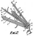
- the cross-arm 1 has two first insulating members 2 and two second insulating members 3 each attached to a conductor support bracket 4 forming an apex or nose of the cross-arm.
- the distal ends of first insulating members 2 are attached to the nose piece 4 by bolted attachment plates 1 1 and the distal ends of second insulating members 3 are attached by bolted fasteners 13.
- first insulating members 2 are provided with attachment plates 10 adapted to permit attachment to the body of a high voltage tower or pylon (not shown). Similar attachment plates 12 are provided at the proximal ends of second insulating members 3.
- the conductor support bracket 4 holds the distal ends of the insulating members 2, 3 and supports the conductors 5 by means of a plate 6 suspended from the cable support bracket 4.
- each first insulating member 2 is provided with a conductive grading ring 9.
- the proximal end of each second insulating member 3 is provided with a conductive grading ring 8.
- a distal conductive grading ring assembly 7 at the apex of the cross-arm 1 includes a conductive post 17 (visible in Figure 6 ) which is in conductive contact with the distal conductive grading ring 7, located centrally therein and extending into the space formed at the apex where the insulating support members 2, 3 meet at the conductor support bracket 4.
- cross-arm 1 is arranged to form a pyramidal structure extending from a quadrilateral base at the tower body to an apex at the conductor support bracket 4.
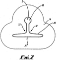
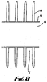
- Figures 7 and 8 show the first insulating members 2 have a spine 8 and sheds 14 disposed along the spine and positioned normal to the long axis of the member.
- a layer of silicone elastomer 20 enrobes the surfaces of the spine 18 and sheds 14 are bonded to the later 20 on the first insulating members 2.
- the cross-sectional profile of spine 18 is substantially an inverted T-shape (i.e. having three rib-like protrusions extending along its axis) with a lobed end to the central body of the T and rounded ends at the terminations of the arms of the T.
- This cross sectional profile has a minimum second moment of area (about a vertical axis passing through the centroid with the orientation shown in the figure) of 3.6 times that of a circle of equivalent area.
- This cross-sectional profile provides two concave faces 32, 33 between the ribs and one substantially flat or slightly convex face 34.
- the shed 14 is shaped to provide a substantially uniform creepage length around its perimeter.
- the second insulating members 3 have a cylindrical spine and circular sheds 15.
- the surface of the spine is also enrobed in a layer of silicone polymer.
- the sheds 15 are of silicone polymer.
- the second embodiment differs from the first embodiment in that it further includes redundant members 16 interconnecting the insulating members 2, 3 and with the redundant members 16 arranged in a plane substantially parallel to the base formed by the proximal ends of the insulating members 2, 3.
- the proximal ends of the insulating members 2, 3 are bolted to the body of a tower or pylon with the first insulating members 2 substantially horizontal as shown in figure 4 such that the cross-sectional profile of the first insulating members 2 is oriented with the flat face 34 downwards and the concave faces 32, 33 directed upwards and outwards as shown in figure 7 .
- this is an insulating member according to the third aspect of the invention, and would be suitable, for instance, as a support post for a conductor.
- the spine 21 has a ⁇ -shaped cross section with each of three similar rib-like protrusions forming the lobed and rounded arms of the Y.
- This cross sectional profile yields a minimum second moment of area about (a vertical axis passing through the centroid in the configuration shown) of 4.6 times that of a circle of equivalent area.
- Three concave faces 35, 36, 37 are formed between the ribs as indicated in Figure 11 .
- the accompanying silicone sheds 22 are shaped to give a substantially uniform creepage distance around their perimeters, and the spine is enrobed in a silicone polymer layer 26.
- the fourth embodiment shown in figures 10 and 12 is also an insulating member according to the third aspect of the invention and is suitable for use as a post-insulator (or bushing) with conductors 27 running along its length.
- the insulating member is similar in shape to the third embodiment with spine 23 and sheds 24 of similar ⁇ -shape.
- each of the rib-like protrusions forming the arms of the Y is provided with a respective channel or passage 25, towards its distal part, extending along the length of the insulating member through which conductors 27 may be threaded.
- the fifth embodiment shown in Figure 13 is also an insulating member according to the third aspect of the invention and is suitable for use as a post-insulator with conductors 30 running down a single channel along its length.
- the insulating member shown is essentially similar in shape to the third embodiment with spine 28 and sheds 29 of similar ⁇ -shape.
- the difference from the third embodiment is that the central region of the spine 28 is provided with a channel or passage 31, extending along the length of the insulating member through which a conductor 30 may be threaded.
- first insulating cross-arms are substantially horizontal in use for the first and second embodiments set out above
- a configuration of the cross-arm in which the first insulating members are inclined to the horizontal in use would also be suitable for the invention.
- the first insulating members could incline upwards at an angle of say 20° to the horizontal in use, from the proximal to the distal ends.
- the sheds on the first insulating members are shown only as varying in size towards the apex of the cross-arm (to facilitate fitting to the cable support bracket 4), the first insulating arm could instead by provided with sheds of alternating large and small cross sections, as shown for the first insulating members.
- the second insulating members 3 may contain sheds of all the same size rather than alternating.
- the cross-arm may be provided with arcing horns/co-ordination gaps for the purposes of insulation co-ordination, as is well known in the field of high voltage insulation assemblies.
Landscapes
- Engineering & Computer Science (AREA)
- Architecture (AREA)
- Civil Engineering (AREA)
- Structural Engineering (AREA)
- Insulators (AREA)
- Suspension Of Electric Lines Or Cables (AREA)
- Insulating Bodies (AREA)
Description
- The present invention relates to insulating members suitable for use in high voltage electrical power networks and methods for their production. The insulating members are able to withstand compressive buckling and bending forces. The invention also relates to cross-arms for power network towers which incorporate such members and towers with such cross-arms.
- Electricity transmission networks are based on designs dating back to the early 20th century. In recent times, as the demand for electricity has increased and more power is generated from dispersed, renewable energy sources, high voltage transmission networks are approaching full capacity with increasing risks of overloading certain routes. The IEC standards define high voltage (HV) as greater than 1 kV. Typically, high voltage transmission lines operate at voltages in excess of 100kV, perhaps several hundred kV. Typical voltages used in power networks are 275kV and 400kV but voltages up to 1 MV or more may be used.
- Although it is possible to build new networks, this is costly, time consuming and can meet opposition from local residents. An alternative to installing a new power system would be to upgrade power carried by the existing networks by either increasing the voltage or the current for the existing transmission lines. Increasing the current on an existing circuit can lead to an increased amount of conductor sag through conductor heating and this can cause infringement of ground clearance regulations. Increasing the voltage on an existing circuit will cause a greater risk of flashover (short circuit to earth or between phases) and may result in the system being in breach of statutory regulations. Either solution will also lead to increased electromagnetic fields at ground level. The requirements for minimum ground clearances, a reliable system (i.e. one that does not flashover) and limits on the electromagnetic field strength at ground level mean that the possibility of increasing voltages or currents for existing tower designs is limited. These issues also limit the ability to make existing tower designs more compact. In common usage, support towers for high voltage power systems are also referred to as pylons.
- A conventional tower has a body made of steel, with steel cross-arms, usually fabricated from L-section high tensile steel members. The conductors are held suspended from the ends of cross-arms by insulators. For a 275kV system, the insulators would typically be about 2.5 m in length. The insulators hold the suspended conductors under tension and keep them spaced from the tower body and from the cross-arm itself. The height of the lowest cross-arm above ground level must take into account sag of the transmission lines due to the combined effects of ambient temperature, temperature rise from solar radiation and temperature rise from resistive heating. The electromagnetic field levels at ground level generated from the transmission conductors must also be considered. It is also important that the conductors are held high enough above ground that the minimum statutory clearance is not breached. The length of the cross-arm must be sufficient to ensure that conductor swing (through wind-driven oscillations of the insulator) does not lead to the conductors coming into close proximity to the tower body, ensuring a low risk of flashover to the pylon body. In addition to being capable of bearing the weight of the transmission conductors, the cross-arm must also be strong enough to bear the additional loads that may arise, for instance, as a result of conductor icing, wind loads, conductor breakage (which could lead to high lateral forces on a cross-arm) or a combination thereof.
- Insulators used for suspending conductors from pylon cross-arms are typically provided with sheds spaced along their length in order to increase the creepage path (i.e. the shortest distance between the ends of the insulator measured over the surface). In order to inhibit current leakage by surface conduction, a ratio of creepage distance to insulator length of at least 2 is desirable.
- It is desirable to be able to increase the voltage rating or current rating for power transmission networks without the need to replace existing tower bodies and without increasing the risk of flashover. It is also desirable to reduce electromagnetic field strength at ground level near towers. It is also desirable to be able to design tower bodies that are more compact than existing designs.
-
British Patent GB 1 ,034,224 - Japanese patent publication
JP06-335144 - British patent
GB 919,534 claim 1, describes cross-arms for supporting overhead electric lines comprising one or more members, each of substantially uniform cross-section throughout its length, of resin bonded glass fibre, in which substantially all of the fibres are substantially parallel to each other and to the longer axis of the member, and having a cast body of thermosetting or cold-setting synthetic resin in which the member or members is or are embedded in such a way that each occupies substantially the whole length of the body. - It has now been realised by the inventors that the conductive cross-arms of a conventional tower or pylon can be replaced by cross-arms formed from insulating members, provided that one or more insulating members making up the cross-arm can be formed in such a way that they are resistant to buckling due to the compressive forces which may be experienced by a tower cross-arm in use. By dispensing with a dangling insulator and replacing it by a strong yet lightweight insulating cross-arm, it has been found that the conductors may be suspended directly from the end of the cross-arm, allowing a voltage increase without an increased risk of flashover. If the insulating cross-arm is kept at the same height as a corresponding conventional conductive cross-arm, the conductors are held higher from the ground and do not swing towards the tower owing to a fixed mounting point. Also, by dispensing with a dangling insulator and replacing it by a strong yet lightweight insulating cross-arm, it has been found that the conductors may be suspended directly from the end of the cross-arm, allowing an increase in the overhead line current carrying capability. This is because, if the insulating cross-arm is kept at the same height as a corresponding conventional conductive cross-arm, the conductors are held higher from the ground and the amount of allowable conductor sag will be increased. Alternatively and for a fixed voltage and current, it has been found that the lowest cross-arm on a tower may be located closer to the ground, even though the transmission conductors are maintained at the same height as for a conventional conductive cross-arm, such that the overall height of the tower body may be reduced or may carry an extra pair of cross-arms for the purpose of, for instance, high voltage direct current (HVDC) transmission or the like.
- Similarly, if voltage or current are increased, such that risk of sag is greater and electromagnetic fields at ground level would be increased, the absence of need for dangling insulators means that conductors may be held higher above the ground, to avoid such problems without the need to increase tower height.
- In addition, removal of the existing suspension insulators between the cross arm and the conductors eliminates conductor swing near the tower body which greatly improves system reliability during high winds.
- Hence it is one object of the invention, amongst others, to provide an insulating cross-arm for a tower formed in such a way that it is resistant to the compressive forces and buckling forces which may be experienced by a tower cross-arm in use, but which is also lightweight and resistant to damage in use. It is another object of the invention to provide insulating members with an improved resistance to buckling which is lightweight and resistant to damage in use.
- Hence, a first aspect of the invention provides an electrically insulating cross-arm for a tower arranged to carry power conductors spaced from a body of said tower, the cross-arm comprising at least one first insulating structural member having a proximal end adapted for attachment to the tower body and a distal end adapted for attachment to a conductor support means, wherein the first insulating structural member comprises or consists essentially of a solid rigid spine extending along a long axis between the distal and proximal ends and wherein the spine has a cross sectional profile, normal to the long axis, having a centroid and wherein the second moment of area of the cross sectional profile about every axis normal to the long axis and dissecting the centroid has a value of A2/2π or more, where A is the area of the cross sectional profile characterised in that: the rigid spine comprises three rib-like protrusions extending along the axis, arranged to form at least two substantially concave faces therebetween such that the cross-sectional profile of the rigid spine is substantially T or Y shaped, the rib-like protrusions providing the arms of the T or Y shape.
- This ensures that the first insulating structural members are adapted to resist buckling and compressive loading.
- A second aspect of the invention provides an insulating structural member, for use with high voltage power networks, comprising or a solid rigid spine extending along a long axis between the distal and proximal ends, wherein the spine has a cross sectional profile, normal to the long axis, having a centroid, and wherein the second moment of area of the cross sectional profile about every axis normal to the long axis and dissecting the centroid has a value of A2/2π or more, where A is the area of the cross sectional profile, and characterised in that the rigid spine comprises three rib-like protrusions extending along the axis arranged to form at least two substantially concave faces therebetween such that cross-sectional profile of the rigid spine is substantially T or Y shaped, the rib-like protrusions providing the arms of the T or Y shape; and wherein the insulating structural member is provided with sheds whereby a creepage distance along the insulating structural member exceeds its length.
- According to the present invention there is provided an apparatus and method as set forth in the appended claims. Other features of the invention will be apparent from the dependent claims, and the description which follows.
- The features set out below in the detailed description of the invention are applicable to all aspects of the invention, where appropriate, and may be combined together as desired.
- For the sake of clarity, throughout this specification, the term "comprising" or "comprises" means including the component(s) specified but not to the exclusion of the presence of others. The term "consisting essentially of or "consists essentially of means including the components specified but excluding other components except for materials present as impurities, unavoidable materials present as a result of processes used to provide the components, and components added for a purpose other than achieving the technical effect of the invention.
- Whenever appropriate, the use of the term "comprises" or "comprising" may also be taken to include the meaning "consists essentially of or "consisting essentially of.
- The first aspect of the invention provides an electrically insulating cross-arm for a tower. It includes at least one first insulating structural member having a proximal end adapted for attachment to the tower body, for instance by means of a fastening arrangement, such as a bolting plate, for instance, and a distal end adapted for attachment to a conductor support means, again, for instance by means of a fastening arrangement, such as a bolting plate, for instance.
- The first insulating structural member comprises or consists essentially of a rigid spine extending along an axis between its distal and proximal ends. The spine is adapted to resist buckling and compressive loading by having a cross sectional profile, normal to the long axis, having a centroid such that the second moment of area of the cross sectional profile about every axis normal to the long axis and dissecting the centroid has a value of A2/2π or more, where A is the area of the cross sectional profile. In other words, the second moment of area of the cross sectional profile is at least 2.0 times the second moment of area of a hypothetical circular profile centred on the centroid and having the same area as the cross sectional profile.
- The concept of second moment of area is used in structural engineering to provide a parameter that can be used to predict the resistance of beams to bending and deflection. The deflection of a beam under load depends not only on the load, but also upon the geometry of the beam's cross-section and its length. This is why beams with higher second moments of area, such as I-beams, are more frequently used in building construction than other beams with the same cross-sectional area (for instance cylindrical rods). The second moment of area gives an estimate of the distribution of material about an axis, and the skilled person will be aware that a beam cross section having a higher second moment of area, for the same cross-sectional area (i.e. weight) gives a greater resistance to deformation for the beam of higher second moment of area It should be noted that in this description, the moment of area is measured about axes passing through the centroid of the cross sectional profile and normal to the long axis of the spine. The cross sectional profile lies in a plane normal to the long axis such that the second moment of area is measured about axes coplanar with the cross sectional profile.
- Suitably, the second moment of area about the axes dissecting the centroid is at least 2.0 times the second moment of area of a hypothetical circular profile centred on the axis and having the same area as the cross-sectional profile of the spine, preferably at least 3.0 times, more preferably at least 4.0 times. In other words, the second moment of area is at least 2.0 times that of a cylindrical rod having the same cross-sectional area (and hence the same weight if made of the same material). This value has been found to provide adequate resistance to deformation for the solid insulating structural members.
- The second moment of area about an axis is easily measured by simple integration of the value for (area x (distance from axis)2) for the cross sectional profile and comparing it to the value for a circle of equivalent area (i.e. A2/4π, where A is the area of the circle) about an axis in the plane of the circle and passing through its centre.
- Hence, the second moment of area of the cross sectional profile about every axis normal to the long axis and dissecting the centroid has a value of A2/2π or more, preferably 3A2/2π, and may be 2A2/π or more. This defines a "minimum" second moment of area for the cross-sectional profile which is the lowest value obtained about any of the specified axes. Preferably, the minimum second moment of area has a value of 4A2/π or less, or even 3A2/π or less, and may be 2A2/π or less. Excessively high values for the second moment of area may lead to a shape which is prone to local buckling. In order to increase the second moment of area, it is necessary to provide some sections of profile which are relatively thin. Excessively high second moments of area may also result in a cross-sectional profile which is prone to build-up of deposits and trapping of pollutants because of multiple concave faces.
- The spine is suitably substantially uniform in cross-sectional profile and in cross-sectional area along its length such that it may be formed by pultrusion. However, it may be non-uniform. For instance, the cross sectional area may taper from a larger area at the proximal end of the spine to a smaller area at the distal end of the spine. Preferably, the spine is of unitary construction. Hence, the spine of the invention has good resistance to bending without the need for multiple parallel spines joined by traverse members, such as disclosed in
GB1 , 034,224 - The cross-arm's resistance to buckling may be improved by the addition of a second insulating structural member having a proximal end adapted for attachment to said tower body and a distal end adapted for attachment to the conductor support means, the second insulating structural member being adapted to resist at least tensile loading. Hence the second member may act in use as a tensile support arm for the conductor support means whilst the first member acts to support compressive forces directed through the conductor support means and acts to resist buckling. Hence the second insulating structural member does not have to be adapted to resist compressive stresses or buckling forces, though it may be so adapted.
- Typically, the cross-arm of the invention in use on a tower will have one, usually two or more first insulating structural members positioned substantially horizontally and connected to the conductor support means at a nose or apex below one, usually two or more second insulating structural members connected to the conductor support means at the nose or apex such that the second insulating structural member or members support the conductor support means under tension.
- In a preferred configuration, the cross-arm in use comprises two first insulating structural members located below two second insulating structural members together arranged to form a pyramidal structure extending from a quadrilateral base at the tower body to an apex at the conductor support means. By pyramidal is meant a shape having a quadrilateral base, the corners of the base connected to an apex. Other configurations such as a tetrahedral arrangement are also suitable (i.e. a triangular base with the vertices of the triangle connected to an apex).
- Preferably, proximal conductive grading rings are provided at the proximal ends of the first and second insulating structural members. A grading ring is a conductive member, usually of a conductive metal, arranged to encircle an insulator where it is connected to a conductor. The grading ring serves to reduce high electric fields and to reduce damage to the insulators from any electrical discharge created by these high electrical field stresses caused by the system geometry, sharp edges, bolt heads or the like on attachment plates joining the proximal ends of the insulating structural members to the tower body.
- Preferably, a further distal conductive grading ring assembly is provided at the apex or nose of the cross-arm, particularly when this is a pyramidal structure.
- The distal conductive grading ring assembly preferably comprises a distal grading ring arranged to encircle the distal ends of the first and second insulating members and a conductive post in conductive contact with the distal grading ring, located centrally within the distal grading ring and extending into a space formed between the distal ends of the first and second insulating members. The central conductive post assists in ensuring a managed electrical field around each of the insulating structural members meeting at the apex or nose of the cross-arm at the conductor support means.
- The distal conductive grading ring as detailed herein may be of use with any insulating cross-arm assembly, and is not particularly limited for use with the cross-arm assembly of the invention.
- The cross-arm may comprise one or more redundant members arranged to interconnect the insulating first and second structural members, the one or more redundant members adapted to resist tension or compression.
- The cross-arm, especially when in the form of a tetrahedral or pyramidal structure, suitably comprises redundant members arranged to interconnect the insulating first and second structural members, the redundant members adapted to resist tension or compression. The use of redundant members is known for the purpose of increasing the load bearing capacity of framework structures. Preferably, the redundant members are configured substantially parallel to a plane of the base of the cross-arm. More preferably, redundant members that are not configured substantially parallel to the plane of the base of the cross-arm are not present. The redundant members may be insulating, conducting or semiconducting members. By "redundant members" is meant structural members capable of withstanding tension and compression, such as suitable beams, rods or bars, which although not required to support load, produce or maintain structural stability. Their presence may be desirable either to increase the load bearing capacity of a structure (if the cross sectional profiles of insulating members are left unchanged) or to permit reduction in cross sectional area of the insulating members (with a corresponding decrease in overall weight for the same load bearing capacity of cross-arm).
- In general the rigid spine of such a first insulating member may comprise at least two rib-like protrusions extending along the longitudinal axis, arranged to form at least one substantially concave face therebetween.
- Such rib-like protrusions may be flat, shaped or lobed, and may meet to form the concave face therebetween at an angle or at a fillet, a fillet being a curve inside an angle serving to prevent concentration of stress. If flat, the protrusions may be referred to as arms, if rounded, as lobes. Other arrangements are referred to as "shaped", so for instance four petal-shaped elliptical ribs meeting at the spine would yield a cross-sectional profile of a flower shape. For instance the rigid spine may have the form of an L section, where the two ribs are flat ribs with a 90° angle between them forming the concave face, or the rigid spine may have the form of an I-beam, where each rib is a T-shaped rib joined together at the bases of the T-shape to give an I-profile with two concave faces on each side of the I. Such an arrangement of two or more rib-like protrusions serves to provide a rigid spine having a cross-sectional profile with the required high second moment of area. The requirement for a concave face means that there is a distribution of material away from the axis leading to augmentation of the second moment of area of the cross-sectional profile.
- An alternative way to describe the cross-sectional profile of the rigid spine is using the terminology of "webs" and "flanges". For an I-beam, the web is the centra) pillar of the I and the top and bottom cross-pieces are known as flanges. Webs generally extend outwards from or through the centroid of a cross-sectional profile with flanges mounted at the end of a web. Hence the web serves to provide a means for holding the material in the flange at a location distant from the centroid, thus serving to assist in providing a higher second moment of area about the centroid. Hence, the rib-like protrusions described herein may be considered as webs extending from a central region of a cross-sectional profile and optionally provided with flanges at their distal ends. Hence a T-beam could be considered as a web, the central arm of the T, with a flange at one end (the cross-arm of the T), or may be considered as three webs each extending out from the crossing point of the T. A Y-beam could be considered as three webs each extending out from the centre of the Y
- According to one first aspect of the invention however, to achieve a high second moment of area, the rigid spine comprises three rib-like protrusions extending along the axis, arranged to form at least two substantially concave fillets therebetween. The cross-sectional profile is T-shaped or Y-shaped, with the three rib-like protrusions forming the arms. The ends of the arms may be rounded or lobed or, for instance, provided with flanges.
- In a particularly preferred arrangement, the ribs are arranged to provide two concave faces and one flat or convex face therebetween. This may be described, for instance, as a T-shaped arrangement where one of the faces of the T (the top of the T) is flat or a drooping T or mushroom cross-section where the top face of the mushroom is convex. The ends of the arms of the T or mushroom shape are suitably rounded or lobed.
- Suitably, the cross-arm is adapted for positioning in use such that the first insulating member is positioned with the concave faces directed upwards and outwards, and the flat or convex face directed downwards, whereby water-run-off is facilitated. The cross-arm may be positioned with the axis of the rigid spine in a substantially horizontal configuration, but may be positioned such that it lies at an angle to the horizontal in use.
- In use, the first insulating members are prone to weather, surface contamination by pollutants and build up of deposits from algae or lichen growing on surfaces of the rigid spine. For this reason, an arrangement with three rib-like protrusions is preferred in order to minimise the number of concave fillets between ribs, whilst maintaining high second moment of area, such that collection of water or debris in use is reduced.
- An arrangement with two concave faces and one flat or convex face therebetween is particularly preferred because such a first insulating member may be positioned in use with the flat or concave face facing downwards and the concave surfaces facing upwards and outwards, with the axis of the rigid spine in a substantially horizontal configuration. The shape of the concave surfaces may be chosen to encourage water-run-off, so that collection of water or deposits in or on these surfaces may be obviated. As for the bottom flat or convex surface, this will not be highly shaded in use and so the growth of shade-loving algae or lichens will be reduced. Hence the configuration provides an arrangement for the first insulating structural member that is strong and lightweight, resistant to buckling and compressive stress and yet which is also positionable in use to avoid build up of water or deposits which may lead to degradation of the insulative properties of the member.
- The second insulating members may have any suitable cross-sectional profile as they do not have to be able to withstand buckling forces or compressive forces, so for instance a simple circular cross-sectional profile may be employed as this profile is also useful to avoid build up of water or deposits which may lead to degradation of the insulative properties of the member.
- Suitably, the cross-sectional profile of the rigid spine of the first insulating structural member has a curved perimeter such that the curved perimeter has a radius of curvature at all points thereon whose magnitude is greater than 1%, of the greatest width of the cross-sectional profile measured along all axes dissecting the centroid, preferably greater than 2%. Typically, this will be greater than 5mm at all points thereon, preferably greater than 10 mm, more preferably greater than 20mm. This ensures that sharp concave angles which may lead to collection of debris or sharp convex angles prone to damage of the insulating surface and subsequent electrical discharge following damage are avoided.
- Suitably, the insulating structural members are provided with sheds whereby a creepage distance along each insulating member exceeds its length: typically the creepage distance is up to 5.5 times the actual length of an insulating member, say from 2 to 5 times the length. Sheds are items which are commonplace in the field of electrical insulators and for a typical insulator the shed is a circular disc or plate, usually of glass or silicone polymer, having a central aperture allowing it to be threaded onto the spine of the insulator. Sheds may also be directly moulded onto an insulating structural member, along with a silicone coating layer, directly onto the spine using silicone moulding, for instance a Liquid Silicone Moulding (LSM) process.
- Several sheds are typically spaced substantially evenly along the length of an insulator and attached to it, the plane of the disc or plate lying normal to the long axis of the insulator. The shed may be provided with concentric circular ribs to increase the creepage length. Sheds increase the distance that any surface leakage current must traverse in order to reach earth. Sheds also assist in disrupting any leakage paths that may arise from water (e.g. rain) trickling over the surface of an insulating member. The creepage distance required for any particular situation will depend upon factors such as rain, humidity and pollution levels. Pollution build-up may increase the electrical conductivity of the surface of an insulating member and so encourage a conductive surface pathway. Greater creepage lengths are required for high pollution districts.
- Sheds useful for the present invention may be shaped such that a creepage path length contributed by each shed is substantially the same around its entire perimeter. In other words, rather than having a conventional circular shape, the shed shape may be tailored to substantially follow or be similar to the shape of the cross-sectional profile of the rigid spine of the first insulating structural members. This arrangement prevents wastage of shed materials (as the shortest creepage path will be the path followed for discharge) and assists in reducing the weight of the cross-arm of the invention.
- The insulating members are solid and free of substantial voids. This is because voids may lead to water condensation within the insulating members leading to risk of electrical discharge. The insulating members used in the cross-arms of the invention are preferably free of structural hollows or channels extending along their lengths, and do not, for instance, include hollow sections. Clearly, with any industrial scale manufacturing process, such as pultrusion, small, unavoidable voids may be present in a structure. By "solid" in this specification it is meant free from deliberately formed hollows, voids or channels.
- Another aspect of the invention provides a tower for high voltage power networks comprising one or more cross-arms according to the first aspect of the invention.
- A second aspect of the invention provides an insulating structural member, for use with high voltage power networks, comprising a rigid spine extending along a long axis between the distal and proximal ends' and wherein the spine has a cross sectional profile, normal to the long axis, having a centroid and wherein the second moment of area of the cross sectional profile about every axis normal to the long axis and dissecting the centroid has a value of A2/2π or more, where A is the area of the cross sectional profile. The insulating structural member may have a length at least 5 times its greatest width. This is achievable because of the improved resistance to bending afforded by the insulating structural member of the invention, allowing greater length to width ratio than previously available with reduced risk of excessive bending or buckling.
- The greatest width of the cross-sectional profile is the greatest width as measured along all axes dissecting the centroid of the cross-sectional profile. By centroid is meant the centre of area for the cross-sectional profile.
- Preferred values for the second moment of area for the second aspect of the invention are as set out hereinbefore for the first insulating members of the first aspect of the invention.
- In general, the rigid spine of such an insulating structural member may comprise at least two rib-like protrusions extending along the axis, arranged to form at least one substantially concave face therebetween.
- Such rib-like protrusions may be flat, shaped or lobed as set out hereinbefore for the first insulating members of the first aspect of the invention, and may meet to form the concave face therebetween at an angle or at a fillet, a fillet being a curve inside an angle serving to prevent concentration of stress. For instance the rigid spine may have the form of an L section, where the two ribs are flat ribs with a 90° angle between them forming the concave face, or the rigid spine may have the form of an I-beam, where each rib is a T-shaped rib joined together at the bases of the T-shape to give an I-profile with two concave faces on each side of the I. Such an arrangement of two or more riblike protrusions serves to provide a rigid spine having a cross-sectional profile with the required high second moment of area. The requirement for a concave face means that there is a distribution of material away from the centroid leading to augmentation of the second moment of area for the cross-sectional profile.
- According to the second aspect of the invention however, the rigid spine comprises three rib-like protrusions extending along the axis, arranged to form at least two substantially concave fillets therebetween. The cross-sectional profile is T-shaped or Y-shaped, with the three protrusions forming the arms.
- In a particularly preferred arrangement, for use with horizontal positioning of the insulating member, the ribs are arranged to provide two concave faces and one flat or convex face therebetween. This may be described as a T-shaped arrangement where one of the faces is flat or a drooping T or mushroom cross-section where one of the faces is convex.
- Suitably, in use, the insulating member may positioned with the axis of the rigid spine in a substantially horizontal configuration and with the concave faces directed upwards and outwards, and the flat or convex face directed downwards, whereby water-run-off is facilitated. In use, the insulating members are prone to weather, surface contamination by pollutants and build up of deposits from algae or lichen growing on surfaces of the rigid spine. For this reason, the arrangement with two concave faces and one flat or convex face therebetween is preferred because such an insulating member, when intended for use in a horizontal or near horizontal position, may be positioned in use with the flat or concave face facing downwards and the concave surfaces facing upwards and outwards, with the axis of the rigid spine in a substantially horizontal configuration. The shape of the concave surfaces may be chosen to encourage run-off of water, such that collection or pooling of water or deposits in or on these surfaces may be obviated. As for the bottom flat or convex surface, this will not be highly shaded in use and so the growth of shade-loving algae or lichens will be reduced. Hence the configuration provides an arrangement for an insulating structural member that is strong and lightweight, resistant to buckling and compressive stress and yet which is also positionable in use to avoid build up of water or deposits which may lead to degradation of the insulative properties of the member.
- A particularly suitable cross-sectional profile for the rigid spine for a post-insulator (intended to be used with its length set substantially vertically) has been found to be a Y-shape with approximately equal angles (about 120°) subtended between the arms of the Y-shape and with the arms and angles rounded, the arms being substantially of the same length. This gives a member which may be light in weight yet which is highly resistant to buckling and bending and, because of the open angles, has low propensity for build-up of deposits on the concave surfaces. Shapes such as X-shapes (i.e. with four arms or rib-like protrusions) or with five or more arms or rib-like protrusions may present problems because of the smaller angles between the arms leading to shading and build-up of deposits.
- According to the second aspect of the invention, the insulating structural members are provided with sheds, as set out hereinbefore, whereby a creepage distance along each insulating member exceeds its length. Preferably, the sheds are shaped such that a creepage path length contributed by each shed is substantially the same around its entire perimeter.
- When intended for use for suspension of high voltage cables and the like, insulating structural members according to the third aspect of the invention are suitably solid and free of substantial voids. This is because voids may lead to water condensation within the insulating members leading to risk of electrical discharge. The insulating members of the invention, when intended for use in this manner are preferably free of structural hollows or channels extending along their lengths, and preferably do not, for instance, include hollow sections.
- However, when intended for use, for instance, as post insulators (sometimes referred to as bushings in the art) for a substation, it may be necessary to provide one or more openings or channels extending along the length of the insulating member so that high voltage conductors may pass through the body of the insulator into a sub-station, for instance. Hence the insulating structural member of the third aspect of the invention may be optionally provided with one or more channels adapted to permit high voltage conductors to extend through the insulating structural member. However, in this situation, the opening or channel may suitably be filled with an insulating oil or a silicone compound (or even a highly insulating gas such as sulphur hexafluoride). The third aspect of the invention, when used as a post insulator or bushing to carry conductors into, for instance, a substation, may be particularly useful when one or more, such as two or more channels for carrying conductors are provided in the rib-like protrusions, for instance towards their distal parts. In other words, channels for carrying conductors may be situated in the rib-like protrusions, typically extending along the length of the spine substantially parallel to the long axis of the spine, with the channels spaced from the centroid of the insulating structural member. Hence, preferably, the insulating structural member has at least one of the rib-like protrusions comprising a channel suitable for carrying a conductor. These channels may be instead of, or in addition to, a channel situated at or near the centroid of the insulating member. The channels are suitable adapted to snugly encase conductors whereby void space is reduced, and any remaining void space within a channel in use, with conductor in place, will be filled with an insulating compound as set out hereinbefore. In other words, the insulating structural members are substantially solid save for channels dimensioned to be as small as possible to permit conductors to extend through (typically along the length) of the insulating structural member.
- Siren that the insulating structural member has a T or Y-shaped cross section, there may be three channels, each located towards the distal ends of each arm of the T or Y, in addition to or instead of a fourth channel at the junction of the arms.
- Compared to conventional post insulators or bushings, which have a single central channel, this arrangement gives the advantage that a single post insulator may be used to carry a plurality of conductors sufficiently spaced from each other to prevent voltage breakdown between them. For instance, three different phases may be carried by a single post insulator. For instance, some channels may be used for carrying high voltage/high current conductors whilst others are used to carry, for instance, cables carrying control signals.
- Preferably, any hollow channels or voids present represent less than 10% of the total volume of the insulating structural members, preferably less than 5%.
- The surface of the insulating structural member of the invention, for use in any aspects of the invention, is suitably hydrophobic, meaning that it shows a contact angle with pure water of 90° or more (measured through the water). This allows water to bead up into droplets on the surface, encouraging them to roll off the surface. Suitably, the surface is resistant to carbonising, such that in the event that the surface is subjected to a high voltage discharge, no permanent conductive carbon track is left. Suitably, the insulating structural member of the invention has a surface coating of a silicone polymer or silicone resin. This also applies to any sheds used in the various aspects of the invention. Typically, the spine will have a silicone sheath bonded to it and sheds moulded from silicone may be adhered or bonded to the sheath covering the insulating member's spine. Alternatively, LS may be used to provide sheds, as set out hereinbefore.
- Furthermore a method may be provided for forming an insulating structural member according to the aspect of the invention above, or for use in the earlier aspects of the invention above, comprising the step of forming the rigid spine by pultrusion.
- Typically, the insulating member may be formed from a glass-fibre reinforced insulating resin such as E (Electrical Grade) or ECR (Electrical Grade Corrosion Resistant) glass fibres with thermosetting resins such as polyester, vinyl ester or epoxy or thermoplastic resins such as polypropylene, polyethylene terephthalate, polybutylene terephthalate, etc.. Other fibres may be used for reinforcement and other suitable insulating polymers may be used with or without reinforcement fibres.
- The method may comprise:
- a) coating the spine with a layer of insulating silicone polymer, and
- b) attaching sheds to the layer of insulating silicone polymer, for instance by use of a silicone glue.
- Alternatively, for instance, the method may comprise providing the spine with a silicone sheath and sheds in a singe silicone moulding process, such as LSM as set out hereinbefore.
- Specific embodiments of the present invention will now be described, by way of example only, with reference to the accompanying drawings in which:
-
Figure 1 shows an isometric view of a cross-arm according to a first embodiment of the first aspect of the invention, -
Figure 2 shows an isometric view of a cross-arm according to a second embodiment of the first aspect of the invention, where substantially in plane redundant members are included, -
Figure 3 shows a rear end view of the second embodiment from the base of the cross-arm, -
Figure 4 shows a side view of the second embodiment of the invention, -
Figure 5 shows an expanded isometric view showing detail of the apex of the cross-arm of the first or second embodiment, -
Figure 6 shows an expanded side cross-sectional view along section A-A fromfigure 3 showing detail of the central conductive post of the grading ring at the apex of the cross-arm of the first or second embodiment, -
Figure 7 shows a cross-sectional view through first insulatingstructural member 2 of the first or second embodiment, with the cross-section taken normal to the long axis of the member along section B-B fromFigure 4 , -
Figure 8 shows a cross-sectional view through first insulatingstructural member 2 of the first or second embodiment along section C-C fromFigure 4 , with the cross-section taken parallel to the long axis of the member, -
Figure 9 shows an insulating member according to a third embodiment of the invention which is according to the third aspect of the invention, -
Figure 10 shows an insulating member according to a fourth embodiment of the invention which is according to the third aspect of the invention, _ -
Figure 1 1 shows a cross-sectional view through the insulating member of the third embodiment shown infigure 9 viewed along section D-D fromFigure 9 , -
Figure 12 shows an insulating member according to the fourth embodiment, with conductors present and -
Figure 3 shows an insulating member according to a fifth embodiment of the invention which is according to the third aspect of the invention and with a conductor present. - Turning to the first and second embodiments as shown in
Figures 1 to 8 , thecross-arm 1 has two first insulatingmembers 2 and two second insulatingmembers 3 each attached to aconductor support bracket 4 forming an apex or nose of the cross-arm. The distal ends of first insulatingmembers 2 are attached to thenose piece 4 by boltedattachment plates 1 1 and the distal ends of second insulatingmembers 3 are attached by boltedfasteners 13. - The proximal ends of first insulating
members 2 are provided withattachment plates 10 adapted to permit attachment to the body of a high voltage tower or pylon (not shown).Similar attachment plates 12 are provided at the proximal ends of second insulatingmembers 3. Theconductor support bracket 4 holds the distal ends of the insulatingmembers conductors 5 by means of a plate 6 suspended from thecable support bracket 4. - The proximal end of each first insulating
member 2 is provided with aconductive grading ring 9. The proximal end of each second insulatingmember 3 is provided with aconductive grading ring 8. A distal conductive grading ring assembly 7 at the apex of thecross-arm 1 includes a conductive post 17 (visible inFigure 6 ) which is in conductive contact with the distal conductive grading ring 7, located centrally therein and extending into the space formed at the apex where the insulatingsupport members conductor support bracket 4. - Hence the
cross-arm 1 is arranged to form a pyramidal structure extending from a quadrilateral base at the tower body to an apex at theconductor support bracket 4. -
Figures 7 and8 show the first insulatingmembers 2 have aspine 8 and sheds 14 disposed along the spine and positioned normal to the long axis of the member. A layer ofsilicone elastomer 20 enrobes the surfaces of thespine 18 and sheds 14 are bonded to the later 20 on the first insulatingmembers 2. The cross-sectional profile ofspine 18 is substantially an inverted T-shape (i.e. having three rib-like protrusions extending along its axis) with a lobed end to the central body of the T and rounded ends at the terminations of the arms of the T. This cross sectional profile has a minimum second moment of area (about a vertical axis passing through the centroid with the orientation shown in the figure) of 3.6 times that of a circle of equivalent area. This cross-sectional profile provides twoconcave faces convex face 34. The shed 14 is shaped to provide a substantially uniform creepage length around its perimeter. - Returning to
Figures 1 to 6 , the second insulatingmembers 3 have a cylindrical spine and circular sheds 15. The surface of the spine is also enrobed in a layer of silicone polymer. Thesheds 15 are of silicone polymer. - The second embodiment differs from the first embodiment in that it further includes
redundant members 16 interconnecting the insulatingmembers redundant members 16 arranged in a plane substantially parallel to the base formed by the proximal ends of the insulatingmembers - In use, the proximal ends of the insulating
members members 2 substantially horizontal as shown infigure 4 such that the cross-sectional profile of the first insulatingmembers 2 is oriented with theflat face 34 downwards and the concave faces 32, 33 directed upwards and outwards as shown infigure 7 . - Turning to the third embodiment of the invention as shown in
figures 9 and11 , this is an insulating member according to the third aspect of the invention, and would be suitable, for instance, as a support post for a conductor. In this embodiment, thespine 21 has a γ-shaped cross section with each of three similar rib-like protrusions forming the lobed and rounded arms of the Y. This cross sectional profile yields a minimum second moment of area about (a vertical axis passing through the centroid in the configuration shown) of 4.6 times that of a circle of equivalent area. Threeconcave faces Figure 11 . The accompanying silicone sheds 22 are shaped to give a substantially uniform creepage distance around their perimeters, and the spine is enrobed in asilicone polymer layer 26. - The fourth embodiment shown in
figures 10 and12 is also an insulating member according to the third aspect of the invention and is suitable for use as a post-insulator (or bushing) withconductors 27 running along its length. The insulating member is similar in shape to the third embodiment withspine 23 and sheds 24 of similar γ-shape. The difference from the third embodiment is that each of the rib-like protrusions forming the arms of the Y is provided with a respective channel orpassage 25, towards its distal part, extending along the length of the insulating member through whichconductors 27 may be threaded. - The fifth embodiment shown in
Figure 13 is also an insulating member according to the third aspect of the invention and is suitable for use as a post-insulator withconductors 30 running down a single channel along its length. The insulating member shown is essentially similar in shape to the third embodiment withspine 28 and sheds 29 of similar γ-shape. The difference from the third embodiment is that the central region of thespine 28 is provided with a channel orpassage 31, extending along the length of the insulating member through which aconductor 30 may be threaded. - It will be appreciated that numerous modifications to the above described embodiments may be made without departing from the scope of the invention as defined in the appended claims. For instance, although the first insulating cross-arms are substantially horizontal in use for the first and second embodiments set out above, a configuration of the cross-arm in which the first insulating members are inclined to the horizontal in use would also be suitable for the invention. For instance, the first insulating members could incline upwards at an angle of say 20° to the horizontal in use, from the proximal to the distal ends. For instance, although the sheds on the first insulating members are shown only as varying in size towards the apex of the cross-arm (to facilitate fitting to the cable support bracket 4), the first insulating arm could instead by provided with sheds of alternating large and small cross sections, as shown for the first insulating members. For instance, the second insulating
members 3 may contain sheds of all the same size rather than alternating. For instance, the cross-arm may be provided with arcing horns/co-ordination gaps for the purposes of insulation co-ordination, as is well known in the field of high voltage insulation assemblies. - The described and illustrated embodiments are to be considered as illustrative and not restrictive in character, it being understood that only the preferred embodiments have been shown and described and that all changes and modifications that come within the scope of the inventions as defined in the claims are desired to be protected. It should be understood that while the use of words such as "preferable", "preferably", "preferred" or "more preferred" in the description suggest that a feature so described may be desirable, it may nevertheless not be necessary and embodiments lacking such a feature may be contemplated as within the scope of the invention as defined in the appended claims. In relation to the claims, it is intended that when words such as "a," "an," "at least one," or "at least one portion" are used to preface a feature there is no intention to limit the claim to only one such feature unless specifically stated to the contrary in the claim. When the language "at least a portion" and/or "a portion" is used the item can include a portion and/or the entire item unless specifically stated to the contrary.
Claims (14)
- An electrically insulating cross-arm for a tower arranged to carry power conductors spaced from a body of said tower, the cross-arm comprising at least one first insulating structural member (2) having a proximal end adapted for attachment to the tower body and a distal end adapted for attachment to a conductor support means, wherein the first insulating structural member (2) comprises a solid rigid spine (18, 21) extending along a long axis between the distal and proximal ends and wherein the spine (18, 21) has a cross sectional profile, normal to the long axis, having a centroid and wherein the second moment of area of the cross sectional profile about every axis normal to the long axis and dissecting the centroid has a value of A2/2π or more, where A is the area of the cross sectional profile, and characterised in that:the rigid spine (18, 21) comprises three rib-like protrusions extending along the axis, arranged to form at least two substantially concave faces (32, 33, 35, 36, 37) therebetween such that the cross-sectional profile of the rigid spine (18, 21) is substantially T or Y shaped, the rib-like protrusions providing the arms of the T or Y shape.
- A cross-arm according to claim 1 wherein the ribs are arranged to provide two concave faces (32, 33, 35, 36, 37) and one flat or convex face (34) therebetween.
- A cross-arm according to any preceding claim adapted for positioning in use such that the first insulating member is positioned with the concave faces (32, 33, 35, 36, 37) directed upwards and outwards, and the flat or convex face (34) directed downwards, whereby water-run-off is facilitated.
- A cross-arm according to any preceding claim wherein the cross-sectional profile of the rigid spine (18, 21) of the first insulating structural member has a curved perimeter such that the curved perimeter has a radius of curvature at all points thereon whose magnitude is greater than 1% of the greatest width of the cross-sectional profile measured along all axes dissecting the centroid.
- A cross-arm according to claim any preceding claim wherein the cross-arm further comprises a second insulating structural member having a proximal end adapted for attachment to said tower body at a base and a distal end adapted for attachment to said tower body at a base and a distal end adapted for attachment to the conductor support means, the second insulating structural member being adapted to resist at least tensile loading.
- A cross-arm according to claim 5 wherein the cross-arm in use comprises two first insulating structural members located below two second insulating structural members together arranged to form a pyramidal structure extending from a quadrilateral base at the tower body to an apex at the conductor support means.
- A cross-arm according to claim 6 wherein proximal conductive grading rings (9) are provided at the proximal ends of the first and second insulating members.
- A cross-arm according to claim 6 or claim 7 wherein a distal conductive grading ring assembly (7) is provided at the apex of the pyramidal structure.
- A cross-arm according to claim 8 wherein the distal conductive grading ring assembly (7) comprises a distal conductive grading ring arranged to encircle the distal ends of the first and second insulating members and a conductive post in conductive contact with the distal grading ring, located centrally within the distal grading ring and extending into a space formed between the distal ends of the first and second insulating members.
- A cross-arm according to any preceding claim wherein the insulating structural members are provided with sheds (14) whereby a creepage distance along each insulating member exceeds its length, and wherein the sheds (14) are shaped such that a creepage path length contributed by each shed is substantially the same around its entire perimeter.
- A tower for high voltage power distribution comprising one or more cross-arms according to any one of claims 1 to 10.
- An insulating structural member, for use with high voltage power networks, comprising a solid rigid spine (18, 21) extending along a long axis between the distal and proximal ends wherein the spine has a cross sectional profile, normal to the long axis, having a centroid, and wherein the second moment of area of the cross sectional profile about every axis normal to the long axis and dissecting the centroid has a value of A2/2π or more, where A is the area of the cross sectional profile, and characterised in that the rigid spine (18, 21) comprises three rib-like protrusions extending along the axis arranged to form at least two substantially concave faces (32, 33, 35, 36, 37) therebetween such that cross-sectional profile of the rigid spine (18, 21) is substantially T or Y shaped, the rib-like protrusions providing the arms of the T or Y shape; and
wherein the insulating structural member is provided with sheds (14) whereby a creepage distance along the insulating structural member exceeds its length. - An insulating structural member according to claim 12 provided with one or more channels adapted to permit high voltage conductors to extend through the insulating structural member.
- An insulating structural member according to claim 13 wherein at least one of the rib-like protrusions comprises a channel suitable for carrying a high voltage conductor.
Applications Claiming Priority (2)
| Application Number | Priority Date | Filing Date | Title |
|---|---|---|---|
| GBGB0914678.8A GB0914678D0 (en) | 2009-08-21 | 2009-08-21 | Support towers, insulating cross-arms and insulating members for high voltage power networks |
| PCT/GB2010/001574 WO2011021006A2 (en) | 2009-08-21 | 2010-08-20 | Support towers, insulating cross-arms and insulating members for high voltage power networks |
Publications (2)
| Publication Number | Publication Date |
|---|---|
| EP2467915A2 EP2467915A2 (en) | 2012-06-27 |
| EP2467915B1 true EP2467915B1 (en) | 2016-03-16 |
Family
ID=41171765
Family Applications (1)
| Application Number | Title | Priority Date | Filing Date |
|---|---|---|---|
| EP10766081.3A Active EP2467915B1 (en) | 2009-08-21 | 2010-08-20 | Support towers, insulating cross-arms and insulating members for high voltage power networks |
Country Status (9)
| Country | Link |
|---|---|
| US (1) | US8895861B2 (en) |
| EP (1) | EP2467915B1 (en) |
| CN (1) | CN102668288B (en) |
| BR (1) | BR112012003875B1 (en) |
| CA (1) | CA2771695C (en) |
| GB (1) | GB0914678D0 (en) |
| MY (1) | MY157632A (en) |
| RU (1) | RU2541044C2 (en) |
| WO (1) | WO2011021006A2 (en) |
Families Citing this family (23)
| Publication number | Priority date | Publication date | Assignee | Title |
|---|---|---|---|---|
| GB201208885D0 (en) * | 2012-05-18 | 2012-07-04 | Univ Manchester | A grading device |
| CN103452370B (en) * | 2012-10-25 | 2015-12-16 | 江苏神马电力股份有限公司 | Power grid transmission line complex pole tower and compound cross-arm structure thereof |
| CN104104047B (en) * | 2013-04-02 | 2017-08-25 | 国家电网公司 | Supporting type wind deflection prevention device |
| PT3134947T (en) * | 2014-04-21 | 2020-10-07 | Quanta Associates Lp | TEMPORARY TRANSFER BUS |
| CN104196303B (en) * | 2014-09-01 | 2019-01-08 | 江苏神马电力股份有限公司 | Power transmission tower |
| ITUA20162294A1 (en) * | 2016-04-05 | 2017-10-05 | General Electric Technology Gmbh | SUPPORT STRUCTURE FOR SWITCH CONTACTS FOR HIGH VOLTAGES |
| RU2728638C1 (en) * | 2016-07-26 | 2020-07-30 | Цзянсу Шимер Электрик Ко., Лтд. | Crossarm, as well as angular support containing thereof |
| US10476249B2 (en) * | 2017-05-24 | 2019-11-12 | Lindsey Manufacturing Company | Three-phase transmission line braced post assembly and circuit tower including the same |
| CN107543821B (en) * | 2017-09-07 | 2020-05-05 | 国网四川省电力公司电力科学研究院 | A method for evaluating the growth degree of insulator algae |
| CN107706871B (en) * | 2017-10-30 | 2020-02-14 | 江苏神马电力股份有限公司 | Overhead distribution line |
| CH714403A1 (en) * | 2017-12-04 | 2019-06-14 | Axpo Power AG | Conductor bridging device and use in a retrofit or manufacturing method for overhead power pylons. |
| CN109346249B (en) * | 2018-11-14 | 2023-08-18 | 南方电网科学研究院有限责任公司 | A bus support insulator |
| CN112447338A (en) * | 2019-08-28 | 2021-03-05 | 国家电网有限公司 | +/-1500 kV segmented composite insulator strain insulator string for high-altitude area test |
| EP3813082B1 (en) * | 2019-10-21 | 2023-07-19 | Hitachi Energy Switzerland AG | Insulator shed having non-circular tip |
| RU2736874C1 (en) * | 2019-12-25 | 2020-11-23 | Общество С Ограниченной Ответственностью "Форэнерго-Инжиниринг" (Ооо "Форэнерго-Инжиниринг" | Insulating cross member |
| AU2021233038A1 (en) * | 2020-03-12 | 2022-11-03 | Quanta Associates, L.P. | Apparatus, system and method for lifting and manipulating conductors |
| CN112289524B (en) * | 2020-10-22 | 2021-07-30 | 广东电网有限责任公司电力科学研究院 | Combined insulator for improving electric field distribution of composite insulator of direct current transmission line |
| US12104395B2 (en) | 2021-02-24 | 2024-10-01 | Jiangsu Shemar Electric Co., Ltd. | Composite crossarm and power transmission tower |
| CN112878787B (en) * | 2021-02-24 | 2025-08-12 | 江苏神马电力股份有限公司 | Composite cross arm and power transmission tower |
| US20230097482A1 (en) * | 2021-09-27 | 2023-03-30 | Preformed Line Products Co. | Insulator support pins |
| CA3216620A1 (en) * | 2022-07-06 | 2024-01-06 | Yanan Gu | Composite crossarm and power transmission tower |
| WO2024193539A1 (en) * | 2023-03-22 | 2024-09-26 | 上海神马电力工程有限公司 | Cross arm assembly and power transmission tower |
| CN221761552U (en) * | 2023-10-17 | 2024-09-24 | 上海神马电力工程有限公司 | A transmission tower |
Citations (2)
| Publication number | Priority date | Publication date | Assignee | Title |
|---|---|---|---|---|
| GB919534A (en) * | 1959-10-07 | 1963-02-27 | British Insulated Callenders | Cross arms for supporting overhead electric lines |
| WO2010037634A1 (en) * | 2008-10-01 | 2010-04-08 | Siemens Aktiengesellschaft | Electrical device having a support frame |
Family Cites Families (13)
| Publication number | Priority date | Publication date | Assignee | Title |
|---|---|---|---|---|
| FR699040A (en) | 1929-07-18 | 1931-02-09 | Rommler A G H | Installation of overhead line insulators for high voltage transmission |
| US3264401A (en) * | 1963-10-29 | 1966-08-02 | Ohio Brass Co | Suppressors for transmission line conductors |
| GB1034224A (en) * | 1964-04-21 | 1966-06-29 | British Insulated Callendar S | Improvements in electric insulators |
| US3296358A (en) * | 1964-07-09 | 1967-01-03 | Lapp Insulator Co Inc | Strut-suspension conductor support |
| US3586758A (en) * | 1969-11-04 | 1971-06-22 | Chance Co Ab | Insulated cantilever standoff conductor support |
| US4523054A (en) * | 1983-04-04 | 1985-06-11 | Interpace Corporation | Line-past insulator support system, method of assembly thereof, and clamp for use therein |
| FR2612549B1 (en) * | 1987-03-20 | 1989-06-30 | Cahors App Elec | INSULATING ARM FOR ELECTRIC LINE SUPPORT POST AND MANUFACTURING METHOD THEREOF |
| SU1688342A1 (en) * | 1989-03-30 | 1991-10-30 | Украинское Отделение Всесоюзного Государственного Проектно-Изыскательского И Научно-Исследовательского Института "Сельэнергопроект" | Subcircuit of aerial power line of low voltage with insulated wires |
| CH685078A5 (en) * | 1992-06-15 | 1995-03-15 | Hubbell Inc | Insulator with internal implementation. |
| JP3212763B2 (en) * | 1993-05-21 | 2001-09-25 | 株式会社巴コーポレーション | Power pole arm |
| US6621009B1 (en) | 2000-11-13 | 2003-09-16 | Mitsubishi Denki Kabushiki Kaisha | Electrical conductor support insulator |
| JP2004213984A (en) | 2002-12-27 | 2004-07-29 | Ngk Insulators Ltd | Polymer post insulator and its mounting method |
| WO2009049376A1 (en) * | 2007-10-19 | 2009-04-23 | Farallon Capital Pty Ltd | Power line supporting apparatus |
-
2009
- 2009-08-21 GB GBGB0914678.8A patent/GB0914678D0/en not_active Ceased
-
2010
- 2010-08-20 BR BR112012003875A patent/BR112012003875B1/en active IP Right Grant
- 2010-08-20 EP EP10766081.3A patent/EP2467915B1/en active Active
- 2010-08-20 MY MYPI2012000768A patent/MY157632A/en unknown
- 2010-08-20 CN CN201080047522.7A patent/CN102668288B/en active Active
- 2010-08-20 WO PCT/GB2010/001574 patent/WO2011021006A2/en not_active Ceased
- 2010-08-20 RU RU2012110574/07A patent/RU2541044C2/en active
- 2010-08-20 CA CA2771695A patent/CA2771695C/en active Active
-
2012
- 2012-02-20 US US13/400,400 patent/US8895861B2/en active Active
Patent Citations (2)
| Publication number | Priority date | Publication date | Assignee | Title |
|---|---|---|---|---|
| GB919534A (en) * | 1959-10-07 | 1963-02-27 | British Insulated Callenders | Cross arms for supporting overhead electric lines |
| WO2010037634A1 (en) * | 2008-10-01 | 2010-04-08 | Siemens Aktiengesellschaft | Electrical device having a support frame |
Also Published As
| Publication number | Publication date |
|---|---|
| BR112012003875B1 (en) | 2020-05-19 |
| US8895861B2 (en) | 2014-11-25 |
| CA2771695A1 (en) | 2011-02-24 |
| WO2011021006A8 (en) | 2012-03-08 |
| BR112012003875A2 (en) | 2017-05-23 |
| RU2541044C2 (en) | 2015-02-10 |
| CN102668288A (en) | 2012-09-12 |
| RU2012110574A (en) | 2013-09-27 |
| WO2011021006A9 (en) | 2012-04-26 |
| GB0914678D0 (en) | 2009-09-30 |
| CA2771695C (en) | 2016-11-01 |
| WO2011021006A3 (en) | 2012-02-02 |
| EP2467915A2 (en) | 2012-06-27 |
| WO2011021006A2 (en) | 2011-02-24 |
| MY157632A (en) | 2016-07-15 |
| US20120205139A1 (en) | 2012-08-16 |
| CN102668288B (en) | 2015-06-24 |
Similar Documents
| Publication | Publication Date | Title |
|---|---|---|
| US8895861B2 (en) | Structural insulator | |
| AU2018360214B2 (en) | Overhead power distribution line | |
| EP3988741B1 (en) | Power transformation framework | |
| CN117722076A (en) | Stay wire tower | |
| CN212626524U (en) | Power transformation framework | |
| CN212626526U (en) | Power transformation framework | |
| US3291899A (en) | Electric insulators in the form of framed structures incorporating rods of resin bonded fibre | |
| US4625839A (en) | Overhead trolley wire insulated support post | |
| CN220954930U (en) | Composite cross arm and terminal rod | |
| CN111864544B (en) | A substation architecture | |
| CN212849300U (en) | Power transformation framework | |
| CN212359262U (en) | Power transformation framework | |
| CN213043236U (en) | Power transformation framework | |
| CN214273121U (en) | cable tower | |
| CN212359263U (en) | Power transformation framework | |
| CN111864543B (en) | A substation architecture | |
| CN212626525U (en) | Power transformation framework | |
| CN111864546B (en) | A substation architecture | |
| GB2566670A (en) | Cross-arm for high voltage tower | |
| CN114482674B (en) | Transmission tower renovation method | |
| CN221481573U (en) | Guyed Tower | |
| CN212626527U (en) | Power transformation framework | |
| SU1709048A1 (en) | High-voltage support | |
| CN112086866B (en) | A substation structure | |
| CN221150904U (en) | Composite distribution line |
Legal Events
| Date | Code | Title | Description |
|---|---|---|---|
| PUAI | Public reference made under article 153(3) epc to a published international application that has entered the european phase |
Free format text: ORIGINAL CODE: 0009012 |
|
| 17P | Request for examination filed |
Effective date: 20120216 |
|
| AK | Designated contracting states |
Kind code of ref document: A2 Designated state(s): AL AT BE BG CH CY CZ DE DK EE ES FI FR GB GR HR HU IE IS IT LI LT LU LV MC MK MT NL NO PL PT RO SE SI SK SM TR |
|
| DAX | Request for extension of the european patent (deleted) | ||
| 17Q | First examination report despatched |
Effective date: 20140307 |
|
| RAP1 | Party data changed (applicant data changed or rights of an application transferred) |
Owner name: ARAGO TECHNOLOGY LIMITED |
|
| RAP1 | Party data changed (applicant data changed or rights of an application transferred) |
Owner name: ARAGO TECHNOLOGY LIMITED |
|
| GRAP | Despatch of communication of intention to grant a patent |
Free format text: ORIGINAL CODE: EPIDOSNIGR1 |
|
| INTG | Intention to grant announced |
Effective date: 20150915 |
|
| GRAS | Grant fee paid |
Free format text: ORIGINAL CODE: EPIDOSNIGR3 |
|
| GRAA | (expected) grant |
Free format text: ORIGINAL CODE: 0009210 |
|
| AK | Designated contracting states |
Kind code of ref document: B1 Designated state(s): AL AT BE BG CH CY CZ DE DK EE ES FI FR GB GR HR HU IE IS IT LI LT LU LV MC MK MT NL NO PL PT RO SE SI SK SM TR |
|
| REG | Reference to a national code |
Ref country code: GB Ref legal event code: FG4D |
|
| REG | Reference to a national code |
Ref country code: CH Ref legal event code: EP |
|
| REG | Reference to a national code |
Ref country code: IE Ref legal event code: FG4D |
|
| REG | Reference to a national code |
Ref country code: AT Ref legal event code: REF Ref document number: 781955 Country of ref document: AT Kind code of ref document: T Effective date: 20160415 |
|
| REG | Reference to a national code |
Ref country code: DE Ref legal event code: R096 Ref document number: 602010031236 Country of ref document: DE |
|
| RAP2 | Party data changed (patent owner data changed or rights of a patent transferred) |
Owner name: ARAGO TECHNOLOGY LIMITED |
|
| REG | Reference to a national code |
Ref country code: FR Ref legal event code: PLFP Year of fee payment: 7 |
|
| REG | Reference to a national code |
Ref country code: NL Ref legal event code: MP Effective date: 20160316 |
|
| REG | Reference to a national code |
Ref country code: LT Ref legal event code: MG4D |
|
| PG25 | Lapsed in a contracting state [announced via postgrant information from national office to epo] |
Ref country code: NO Free format text: LAPSE BECAUSE OF FAILURE TO SUBMIT A TRANSLATION OF THE DESCRIPTION OR TO PAY THE FEE WITHIN THE PRESCRIBED TIME-LIMIT Effective date: 20160616 Ref country code: FI Free format text: LAPSE BECAUSE OF FAILURE TO SUBMIT A TRANSLATION OF THE DESCRIPTION OR TO PAY THE FEE WITHIN THE PRESCRIBED TIME-LIMIT Effective date: 20160316 Ref country code: HR Free format text: LAPSE BECAUSE OF FAILURE TO SUBMIT A TRANSLATION OF THE DESCRIPTION OR TO PAY THE FEE WITHIN THE PRESCRIBED TIME-LIMIT Effective date: 20160316 Ref country code: GR Free format text: LAPSE BECAUSE OF FAILURE TO SUBMIT A TRANSLATION OF THE DESCRIPTION OR TO PAY THE FEE WITHIN THE PRESCRIBED TIME-LIMIT Effective date: 20160617 |
|
| REG | Reference to a national code |
Ref country code: AT Ref legal event code: MK05 Ref document number: 781955 Country of ref document: AT Kind code of ref document: T Effective date: 20160316 |
|
| PG25 | Lapsed in a contracting state [announced via postgrant information from national office to epo] |
Ref country code: SE Free format text: LAPSE BECAUSE OF FAILURE TO SUBMIT A TRANSLATION OF THE DESCRIPTION OR TO PAY THE FEE WITHIN THE PRESCRIBED TIME-LIMIT Effective date: 20160316 Ref country code: LT Free format text: LAPSE BECAUSE OF FAILURE TO SUBMIT A TRANSLATION OF THE DESCRIPTION OR TO PAY THE FEE WITHIN THE PRESCRIBED TIME-LIMIT Effective date: 20160316 Ref country code: NL Free format text: LAPSE BECAUSE OF FAILURE TO SUBMIT A TRANSLATION OF THE DESCRIPTION OR TO PAY THE FEE WITHIN THE PRESCRIBED TIME-LIMIT Effective date: 20160316 Ref country code: LV Free format text: LAPSE BECAUSE OF FAILURE TO SUBMIT A TRANSLATION OF THE DESCRIPTION OR TO PAY THE FEE WITHIN THE PRESCRIBED TIME-LIMIT Effective date: 20160316 |
|
| PG25 | Lapsed in a contracting state [announced via postgrant information from national office to epo] |
Ref country code: IS Free format text: LAPSE BECAUSE OF FAILURE TO SUBMIT A TRANSLATION OF THE DESCRIPTION OR TO PAY THE FEE WITHIN THE PRESCRIBED TIME-LIMIT Effective date: 20160716 Ref country code: PL Free format text: LAPSE BECAUSE OF FAILURE TO SUBMIT A TRANSLATION OF THE DESCRIPTION OR TO PAY THE FEE WITHIN THE PRESCRIBED TIME-LIMIT Effective date: 20160316 Ref country code: EE Free format text: LAPSE BECAUSE OF FAILURE TO SUBMIT A TRANSLATION OF THE DESCRIPTION OR TO PAY THE FEE WITHIN THE PRESCRIBED TIME-LIMIT Effective date: 20160316 |
|
| PG25 | Lapsed in a contracting state [announced via postgrant information from national office to epo] |
Ref country code: SM Free format text: LAPSE BECAUSE OF FAILURE TO SUBMIT A TRANSLATION OF THE DESCRIPTION OR TO PAY THE FEE WITHIN THE PRESCRIBED TIME-LIMIT Effective date: 20160316 Ref country code: AT Free format text: LAPSE BECAUSE OF FAILURE TO SUBMIT A TRANSLATION OF THE DESCRIPTION OR TO PAY THE FEE WITHIN THE PRESCRIBED TIME-LIMIT Effective date: 20160316 Ref country code: ES Free format text: LAPSE BECAUSE OF FAILURE TO SUBMIT A TRANSLATION OF THE DESCRIPTION OR TO PAY THE FEE WITHIN THE PRESCRIBED TIME-LIMIT Effective date: 20160316 Ref country code: SK Free format text: LAPSE BECAUSE OF FAILURE TO SUBMIT A TRANSLATION OF THE DESCRIPTION OR TO PAY THE FEE WITHIN THE PRESCRIBED TIME-LIMIT Effective date: 20160316 Ref country code: CZ Free format text: LAPSE BECAUSE OF FAILURE TO SUBMIT A TRANSLATION OF THE DESCRIPTION OR TO PAY THE FEE WITHIN THE PRESCRIBED TIME-LIMIT Effective date: 20160316 Ref country code: RO Free format text: LAPSE BECAUSE OF FAILURE TO SUBMIT A TRANSLATION OF THE DESCRIPTION OR TO PAY THE FEE WITHIN THE PRESCRIBED TIME-LIMIT Effective date: 20160316 Ref country code: PT Free format text: LAPSE BECAUSE OF FAILURE TO SUBMIT A TRANSLATION OF THE DESCRIPTION OR TO PAY THE FEE WITHIN THE PRESCRIBED TIME-LIMIT Effective date: 20160718 |
|
| REG | Reference to a national code |
Ref country code: DE Ref legal event code: R097 Ref document number: 602010031236 Country of ref document: DE |
|
| PG25 | Lapsed in a contracting state [announced via postgrant information from national office to epo] |
Ref country code: IT Free format text: LAPSE BECAUSE OF FAILURE TO SUBMIT A TRANSLATION OF THE DESCRIPTION OR TO PAY THE FEE WITHIN THE PRESCRIBED TIME-LIMIT Effective date: 20160316 Ref country code: BE Free format text: LAPSE BECAUSE OF FAILURE TO SUBMIT A TRANSLATION OF THE DESCRIPTION OR TO PAY THE FEE WITHIN THE PRESCRIBED TIME-LIMIT Effective date: 20160316 |
|
| PLBE | No opposition filed within time limit |
Free format text: ORIGINAL CODE: 0009261 |
|
| STAA | Information on the status of an ep patent application or granted ep patent |
Free format text: STATUS: NO OPPOSITION FILED WITHIN TIME LIMIT |
|
| PG25 | Lapsed in a contracting state [announced via postgrant information from national office to epo] |
Ref country code: DK Free format text: LAPSE BECAUSE OF FAILURE TO SUBMIT A TRANSLATION OF THE DESCRIPTION OR TO PAY THE FEE WITHIN THE PRESCRIBED TIME-LIMIT Effective date: 20160316 |
|
| 26N | No opposition filed |
Effective date: 20161219 |
|
| PG25 | Lapsed in a contracting state [announced via postgrant information from national office to epo] |
Ref country code: BG Free format text: LAPSE BECAUSE OF FAILURE TO SUBMIT A TRANSLATION OF THE DESCRIPTION OR TO PAY THE FEE WITHIN THE PRESCRIBED TIME-LIMIT Effective date: 20160616 |
|
| PG25 | Lapsed in a contracting state [announced via postgrant information from national office to epo] |
Ref country code: MC Free format text: LAPSE BECAUSE OF FAILURE TO SUBMIT A TRANSLATION OF THE DESCRIPTION OR TO PAY THE FEE WITHIN THE PRESCRIBED TIME-LIMIT Effective date: 20160316 |
|
| REG | Reference to a national code |
Ref country code: CH Ref legal event code: PL |
|
| PG25 | Lapsed in a contracting state [announced via postgrant information from national office to epo] |
Ref country code: LI Free format text: LAPSE BECAUSE OF NON-PAYMENT OF DUE FEES Effective date: 20160831 Ref country code: CH Free format text: LAPSE BECAUSE OF NON-PAYMENT OF DUE FEES Effective date: 20160831 |
|
| PG25 | Lapsed in a contracting state [announced via postgrant information from national office to epo] |
Ref country code: SI Free format text: LAPSE BECAUSE OF FAILURE TO SUBMIT A TRANSLATION OF THE DESCRIPTION OR TO PAY THE FEE WITHIN THE PRESCRIBED TIME-LIMIT Effective date: 20160316 |
|
| REG | Reference to a national code |
Ref country code: IE Ref legal event code: MM4A |
|
| PG25 | Lapsed in a contracting state [announced via postgrant information from national office to epo] |
Ref country code: IE Free format text: LAPSE BECAUSE OF NON-PAYMENT OF DUE FEES Effective date: 20160820 |
|
| REG | Reference to a national code |
Ref country code: FR Ref legal event code: PLFP Year of fee payment: 8 |
|
| PG25 | Lapsed in a contracting state [announced via postgrant information from national office to epo] |
Ref country code: LU Free format text: LAPSE BECAUSE OF NON-PAYMENT OF DUE FEES Effective date: 20160820 |
|
| PG25 | Lapsed in a contracting state [announced via postgrant information from national office to epo] |
Ref country code: HU Free format text: LAPSE BECAUSE OF FAILURE TO SUBMIT A TRANSLATION OF THE DESCRIPTION OR TO PAY THE FEE WITHIN THE PRESCRIBED TIME-LIMIT; INVALID AB INITIO Effective date: 20100820 Ref country code: CY Free format text: LAPSE BECAUSE OF FAILURE TO SUBMIT A TRANSLATION OF THE DESCRIPTION OR TO PAY THE FEE WITHIN THE PRESCRIBED TIME-LIMIT Effective date: 20160316 |
|
| PG25 | Lapsed in a contracting state [announced via postgrant information from national office to epo] |
Ref country code: TR Free format text: LAPSE BECAUSE OF FAILURE TO SUBMIT A TRANSLATION OF THE DESCRIPTION OR TO PAY THE FEE WITHIN THE PRESCRIBED TIME-LIMIT Effective date: 20160316 Ref country code: MT Free format text: LAPSE BECAUSE OF NON-PAYMENT OF DUE FEES Effective date: 20160831 Ref country code: MK Free format text: LAPSE BECAUSE OF FAILURE TO SUBMIT A TRANSLATION OF THE DESCRIPTION OR TO PAY THE FEE WITHIN THE PRESCRIBED TIME-LIMIT Effective date: 20160316 |
|
| REG | Reference to a national code |
Ref country code: FR Ref legal event code: PLFP Year of fee payment: 9 |
|
| PG25 | Lapsed in a contracting state [announced via postgrant information from national office to epo] |
Ref country code: AL Free format text: LAPSE BECAUSE OF FAILURE TO SUBMIT A TRANSLATION OF THE DESCRIPTION OR TO PAY THE FEE WITHIN THE PRESCRIBED TIME-LIMIT Effective date: 20160316 |
|
| REG | Reference to a national code |
Ref country code: GB Ref legal event code: 732E Free format text: REGISTERED BETWEEN 20220630 AND 20220706 |
|
| REG | Reference to a national code |
Ref country code: DE Ref legal event code: R081 Ref document number: 602010031236 Country of ref document: DE Owner name: HUBBELL POWER SYSTEMS, INC. (N.D. GES. D. STAA, US Free format text: FORMER OWNER: ARAGO TECHNOLOGY LTD., LOUGHBOROUGH, LEICESTERSHIRE, GB |
|
| PGFP | Annual fee paid to national office [announced via postgrant information from national office to epo] |
Ref country code: DE Payment date: 20250709 Year of fee payment: 16 |
|
| PGFP | Annual fee paid to national office [announced via postgrant information from national office to epo] |
Ref country code: GB Payment date: 20250710 Year of fee payment: 16 |
|
| PGFP | Annual fee paid to national office [announced via postgrant information from national office to epo] |
Ref country code: FR Payment date: 20250709 Year of fee payment: 16 |