EP2466901A2 - Depth data upsampling - Google Patents
Depth data upsampling Download PDFInfo
- Publication number
- EP2466901A2 EP2466901A2 EP11191976A EP11191976A EP2466901A2 EP 2466901 A2 EP2466901 A2 EP 2466901A2 EP 11191976 A EP11191976 A EP 11191976A EP 11191976 A EP11191976 A EP 11191976A EP 2466901 A2 EP2466901 A2 EP 2466901A2
- Authority
- EP
- European Patent Office
- Prior art keywords
- horizontal
- bounds
- pixel
- disparity map
- vertical
- Prior art date
- Legal status (The legal status is an assumption and is not a legal conclusion. Google has not performed a legal analysis and makes no representation as to the accuracy of the status listed.)
- Granted
Links
Images


Classifications
-
- H—ELECTRICITY
- H04—ELECTRIC COMMUNICATION TECHNIQUE
- H04N—PICTORIAL COMMUNICATION, e.g. TELEVISION
- H04N13/00—Stereoscopic video systems; Multi-view video systems; Details thereof
- H04N13/10—Processing, recording or transmission of stereoscopic or multi-view image signals
- H04N13/106—Processing image signals
- H04N13/139—Format conversion, e.g. of frame-rate or size
-
- H—ELECTRICITY
- H04—ELECTRIC COMMUNICATION TECHNIQUE
- H04N—PICTORIAL COMMUNICATION, e.g. TELEVISION
- H04N13/00—Stereoscopic video systems; Multi-view video systems; Details thereof
- H04N13/10—Processing, recording or transmission of stereoscopic or multi-view image signals
- H04N13/106—Processing image signals
- H04N13/128—Adjusting depth or disparity
Definitions
- the present invention provides a method and a device for processing 3 dimensional image data by up-sampling a depth map of stereo content, such as in particular a video sequence of digital stereo video, digital stereo images, scanned film print stereo frames through a broadcast live system in real time or through a storage medium such as a hard-disk, scanner, optical disk or the like.
- a depth map of stereo content such as in particular a video sequence of digital stereo video, digital stereo images, scanned film print stereo frames
- a broadcast live system in real time or through a storage medium such as a hard-disk, scanner, optical disk or the like.
- Disparity map estimation is one of the fundamental and most important tools for stereo (multi-view) image processing. As 3D TVs become available in the market, the focus on stereo processing has also gained attention. In that manner, disparity map estimation which gives information about the 3D position of the objects or pixels in the stereo (multi-view) content is inevitable.
- literature there are various methods providing disparity maps from 3D content involving stereo or multi-view video. However, considering the resolution of the 3D content provided by 3D TVs, the computational complexity is very high for providing reliable disparity maps.
- real time disparity map estimation algorithms on embedded systems run on resolutions around (300x200) which are far away from the HD panel resolutions (1920x1080). It is clear that, performing known disparity estimation algorithms on high resolution data do not enable real time applications.
- a joint bilateral up-sampler which uses a high resolution input signal to guide the interpolation of a low resolution solution set derived from a down-sampled version of the input signal from low to high resolution.
- the bilateral filters are window-based filters whose weight depends on the colour similarities and the spatial distance between the centre pixel and the corresponding pixels within a window. Thus, pixels with similar colour coefficients have higher weights, while un-similar pixels have lower weights.
- the weights are determined by colour images and exploited to filter and up scale disparity maps.
- the weighting strategy of bilateral filters provides intensity edges to be preserved, hence the up sampled disparity map involves depth discontinuities at edge regions and smooth variation at un-textured regions.
- Bilateral filters provide high precision up sampling of low resolution data such as disparity maps, tone mapping.
- the information is obtained from the low resolution data by weighted summation within a window ( N , N ).
- D x ⁇ y 1 Wsum ⁇ j ⁇ N ⁇ i ⁇ N w ⁇ I ⁇ x + i , y + j . d x ⁇ ⁇ y ⁇
- x ⁇ and y ⁇ correspond to pixels coordinates of x and y at low resolution disparity map
- d is the low resolution disparity map
- D is the high resolution disparity map
- w() is the weighting function depending on colour similarity and spatial distance
- Wsum is the normalization coefficient yielding the sum of all weights to "1". In order to obtain satisfying up sampling, the size of the filter should be as large as possible.
- bilateral depth up-sampling it is assumed that intensity edges also involve depth discontinuities which is called texture copying. In some cases, the intensity edges may not coincide with depth discontinuities and involve smooth depth variations.
- bilateral filters do not smooth the disparity map at these regions leading to an incorrect up-scaling.
- a further disadvantage of bilateral filters is the computational complexity. The distribution of weights in the filter window change for each pixel, hence pixels do not have strict relations with neighbouring pixels. Therefore, as the window sizes increase, which is directly related to the up-scaling ratio, the computational complexity is increased tremendously.
- the support window may not be connected, which is depending on the colour similarity and spatial distance, wherein there may be gaps between support pixels leading to discontinuities. This fact leads thereto that similar colour pixels on different objects are in the same support regions as the filter size increases, which leads to an incorrect upsampling.
- a method of processing three-dimensional image data by up-sampling low resolution depth data is provided, in particular in the form of a range map or a disparity map of stereo content, such as digital stereo video, digital images, scanned film print stereo frames through a broadcast live system in real time or through a storage medium such as a hard disk, scanner, optical disk or the like, comprising the following successive steps:
- the device of the invention for processing three-dimensional image data by up-sampling low resolution depth data in particular in the form of a range map or a disparity map of stereo content, such as digital stereo video, digital images, scanned film print stereo frames through a broadcast live system in real time or through a storage medium such as a hard disk, scanner, optical disk or the like, comprises
- Up-sampling of low resolution depth maps obtained through stereo estimation or active sensors, according to the observed high resolution colour images is an important tool for reducing computation complexity of stereo processing of three-dimensional data and providing high resolution depth data coinciding with high resolution colour images of the same scene.
- the fundamental approach for the solution of the up-scaling of low resolution disparity or depth maps is performing filtering among the nearest neighbour up-scaled disparity map by utilizing adaptive support windows detected through processing of high resolution colour images.
- the adaptive support windows are determined by detecting vertical and horizontal bounds for each pixel having an intensity range within a threshold. Then, for each pixel, averaging of the disparity values among the detected bounds of the neighbouring pixels located within the bounds of the corresponding pixel is performed.
- summed area table of the nearest neighbour up-scaled disparity map is utilized, which enables averaging on horizontal or vertical direction with one subtraction.
- the vertical and horizontal bounds determine the shape of the adaptive window based on intensity (colour) variation, in that manner color-wise similar pixels are utilized to obtain the high resolution disparity map.
- the adaptive support windows also provide continuous and compact regions during the disparity averaging, which is vital for ignoring unrelated pixels
- the object of the present invention to provide a method and a device for up-sampling a depth map for a stereo content which reduce the computational complexity and achieve a precise high-resolution depth map.
- the reference numbers as used in figures may possess the following meanings; Nearest neighbour up sample (10) Bound detection (20) Adaptive support region filtering (30) 3D content supplier (101) 3D processing unit (102) Depth estimator unit (103) Stereo matching unit (104) Up sampler (105) Depth based processing unit (106) Down sampler (107)
- stereo content can be present in various formats and can be supplied through various sources, which can provide video scenes of digital stereo video, digital stereo images, scanned film print stereo frames through a broadcast live system in real time or storage medium such as a hard-disk, scanner, optical disk or the like.
- the low-resolution depth data can be in the form of a disparity map obtained through stereo image processing or in the form of a range map obtained by active sensors.
- the low-resolution depth data are combined with corresponding high-resolution colour data of the same scene to provide high-resolution depth data with improved precision achieved by the depth data up-sampling according to the invention.
- the high-resolution depth map received by the method of depth data up-sampling according to the invention can be used for virtual view synthesis, depth-based enhancement or related 3D applications for 3D televisions or similar 3D applications in computers, beamers or the like for viewing 3D movies or other 3D content by consumers.
- the estimated disparity map is self-registered with one of the stereo images.
- the low-resolution depth data is in the form of a range map, however, a registration is required between colour data and depth data, which can be achieved by homograph mapping. According to the invention it is assumed that the depth data and the colour data are registered.
- Figure 1 shows the method according to the present invention of up-sampling low-resolution disparity depth maps by exploiting high-resolution colour images of the same scene in two steps.
- the low-resolution disparity map is up-sampled using a nearest neighbour-interpolation (10).
- the high resolution colour image of the same scene as with respect to the first procedure is used to detect the vertical and horizontal bounds (20), which will be explained in more detail.
- an averaging filter is applied among the arbitrary shaped region by the utilization of horizontal and vertical integral data of the disparity map so that adaptive support region filtering (30) leads to the high-resolution disparity map.
- the second procedure involves detecting of adaptive shaped regions for each pixel defining colour-wise similar pixel groups in the high-resolution colour image which is achieved by vertical and horizontal bound search which limits the colour variation within.
- bound search neighbouring pixel bounds are necessary to decrease the computational complexity.
- the averaging filter is applied among the arbitrary shaped region by the utilization of horizontal and vertical integral data of the disparity map, wherein integral data enable the fast computation which is independent from an increase in window sizes.
- the averaging operation within colour-wise similar pixel groups provide crisp, especially at object boundaries, and smooth high-resolution depth data wherein erroneous regions are also corrected in some manner.
- the disparity values are also scaled by the horizontal scaling factor, since disparity is defined among horizontal axis and is directly related to the width of the stereo frames.
- HighDisp x ⁇ y s H .
- the scaling in equation (B) is unsuitable to provide high precision up sampled disparity map. Therefore, adaptive support region filtering operation is performed to refine the disparity map. According to an adaptive support region the idea can be used to estimate disparity maps between stereo pairs.
- the present invention exploits the adaptive support region idea for up sampling and smoothing low resolution disparity maps according to the high resolution colour image rather than stereo disparity map estimation.
- Disparity cost values can be aggregated among support regions and the disparity values providing minimum cost is assigned to the pixels.
- adaptive support region is utilized to filter disparity maps. Adaptive support region for each pixel is determined by detecting vertical and horizontal intensity bounds in the high resolution colour image.
- a search is performed in four directions (up, down, left and right) to determine the colour wise neighbourhood. In any direction, the search continues until the first pixel whose absolute intensity difference with the centre pixel is above a predetermined threshold is reached, which actually forms the bound in the corresponding direction.
- a predetermined threshold is reached, which actually forms the bound in the corresponding direction.
- This search can be performed for each pixel independently which actually increases computation complexity as the search width increases.
- bound detection is performed in a computationally efficient way by enforcing bounds of the neighbouring pixels during the search for a pixel.
- the bounds of left (indexed as 1 ) and upper (indexed as 2 ) neighbour pixels have been detected in the scan order.
- the horizontal bound search of the pixel starts form the left (L 1 ) and right (R 1 ) bounds of the left neighbouring pixel, if the intensity difference of L 1 with the corresponding pixel is below (above) the predefined threshold, search continues in left (right) direction; if the intensity difference of R 1 and the centre pixel is below (above) the threshold, search continues in right (left) direction.
- the bound search in upward direction starts from the upper bound (U 2 ) of the upper neighbouring pixel and the direction is determined according to the intensity difference between U 2 and the centre pixel. If the difference is below (above) the threshold, search continues in upward (downward) direction. The bound search in downward direction starts from the lower bound (D 2 ) of the upper neighbouring pixel and the search direction is determined based on the intensity difference. If the absolute difference is below (above) the threshold, search is conducted in downward (upward) direction. Utilization of the bounds of the neighbouring pixels provides a decrease in the search range, which actually saves almost 50% of the computation of the bound search. The idea in this search is logical, since similar coloured neighbouring pixels have close bounds, hence unnecessary search is prevented.
- the next step involves averaging of disparity values by exploiting the bounds and the disparity maps.
- the adaptive support region for a pixel is extracted by considering horizontal bounds of the pixels in the vertical bound of the corresponding pixel as illustrated in figure 4 .
- This region (3) defines the locally similar coloured pixels around the pixel in an efficient way, and the next step involves an averaging operation of the disparity values within the support region. It is important to note that, calculating the average disparity value among the support region for each pixel requires lots of computation, and as the support region sizes increase, such a process becomes inefficient.
- Horizontal integral image of the disparity map can be utilized to determine the sum of disparity values within a closed horizontal bound easily (equation F), hence for each row illustrated in figure 6 the total disparity value among horizontal bounds are calculated (horizontal gray coloured pixels) and the total disparity value is determined by summation of these values in vertical direction starting from pixel a to pixel b as given in equation (G).
- Equation (G) The vertical summation given in equation (G) can be achieved by integral data as well in order to decrease computational complexity.
- the vertical integral data of the horizontal sum data is obtained via (H)
- the total disparity value within the support region is obtained through one subtraction among the vertical integral data as given in equation (I).
- the computational complexity does not depend on the length of the vertical bounds, which enables the utilization of larger neighbourhood increasing the robustness and precision.
- the average disparity value within the adaptive support region is finally calculated by normalizing the total sum with the number of pixels in the region, which is also determined by summing up the width of the horizontal bounds of the pixels located among the vertical bounds of the corresponding pixel, as in equation (J).
- HorCount gives the width of horizontal bounds for each pixel; in order to calculate the total number of pixels, vertical summation is also required.
- the proposed up sampling method exploits averaging filter among arbitrarily shaped local windows by vertical and horizontal passes.
- the utilization of summed area tables (integral data) provides the independency of the algorithm to the area of the support region.
- the proposed method is much faster than edge preserving joint bilateral up sampling, which is actually a widely utilized algorithm.
- the presented invention provides connected support regions for each pixel, having a compact relation which is not the case in bilateral up-sampling and increasing precision.
- Step 1 Up scale the low resolution input depth map to the desired resolution by nearest neighbour interpolation.
- Step 2 Detect the horizontal and vertical bounds of each pixel on the high resolution colour image depending on the intensity differences.
- right bound RB , left bound LB , upper bound UB and lower bound DB are detected for each pixel.
- Step 3 Obtain the horizontal integral disparity map by utilizing the following formula (E) for each row independently.
- Step 4 For each pixel, calculate the sum of disparity values among horizontal direction by utilizing the horizontal integral image and the horizontal (left and right LB, RB) bounds.
- HSum x ⁇ y HorInt RB x ⁇ y , y - HorInt LB x ⁇ y , y
- Step 6 For each pixel, calculate the total disparity values among the arbitrary support region by one subtraction of lower and upper bounds over the vertical integral data extracted in step 5.
- Sum x ⁇ y VerInt x , DB x ⁇ y - VerInt x , UB x ⁇ y
- Step 7 Calculate the total area of the arbitrary support region for each pixel by vertical and horizontal integral data. First, form the horizontal integral, and calculate horizontal bound widths for each pixel; then form the vertical integral data of the horizontal bounds.
- Step 8 The final disparity value for each pixel is obtained by normalizing the sum value determined in step 6 by support area calculated in step 7.
- DispMap x ⁇ y Sum x ⁇ y Area x ⁇ y
- Depth Data Upsampler is a device that increases the resolution of depth data depending on the high resolution colour image.
- Depth data correspond to 3D structure that can be obtained through a stereo (multi-view) depth estimator or active sensors (IR or laser) that exploit time-of-flight.
- the 3D content supplier (101) provides digital stereo (multi-view) video, images, scanned film print stereo (multi-view) frames or colour and its measured low resolution depth data to a 3D processing unit (102).
- the 3D stereo or multi-view content can be provided through a broadcast live system, or from a stored medium, wherein the colour plus depth can be provided through an active sensor involving IR or laser transmitter and receiver capturing depth data and a camera capturing colour data.
- the 3D processing unit (102) is a device that exploits 3D data for several applications, in that manner the unit (102) can be a part of a 3D TV system, a computer specialised for 3D applications or a processor embedded on active sensors to provide processed depth data.
- 3D processing unit (102) may involve a depth estimator unit (103) for stereo or multi-view content, involves a depth upsampler unit (105) and a depth based processing unit (106).
- depth estimator unit (103) For stereo or multi-view content, depth data is required to be extracted; in that manner, depth estimator unit (103) is specialised for estimating 3D structure.
- a down sampler unit (107) is required to decrease the resolution of the input data so that fast processing can be achieved especially for real-time systems of 3D TVs. The downsampling shrinks the number of depth hypotheses and number of pixels in the images, enabling low computational complexity.
- This unit is followed by a stereo (multi-view) depth estimator or matching unit (104) that extracts 3D structure by pixel matching.
- depth estimator (104) Exploiting down sampled data, the output of depth estimator (104) is low resolution depth map(s) of stereo or multi-view frames. In most cases, low resolution depth data is required to be up sampled especially for depth based applications in 3D TVs and computers.
- the depth data provided from active sensors is also low resolution and up sampling is vital for various applications such as virtual view synthesis.
- the invention refers in particular to a depth up-sampling device (105) and the corresponding method, which are important for 3D processing units in almost every application. Depth up-sampling device (105) gets two inputs, low resolution depth data and the corresponding high resolution colour view.
- depth data can belong to any of the views and its colour data is available; for the colour plus depth case, both are provided through a capturing device or 3D content supplier (101).
- Depth up-sampling device (105) outputs high resolution depth data for the corresponding high resolution colour view by following the steps explained in Figure 1 .
- the high resolution depth data can be used by another unit in the 3D processing unit (102).
- the depth-based processing unit (106) is a module performing any depth driven application involving virtual view synthesis, on scene display embedding, depth based enhancement.
- depth-based processing unit (106) may show variation.
- depth-based processing unit (106) may involve adaptive depth adjustment via virtual view synthesis or depth based enhancement.
- For a computer providing high resolution depth data may be sufficient or virtual tour within the 3D content can be achieved by virtual view synthesis.
- For an embedded processor on an active sensor providing high resolution depth data can be sufficient.
- the present invention provides a method and a device for up-sampling low resolution depth data of a video sequence to higher resolution.
- the invention provides the ability for systems estimating depth maps to process at lower resolutions so that the computational complexity is reduced wherein the estimated depth maps are up-sampled to the original video resolution.
- the registration of low resolution depth information gathered from active sensors to high resolution colour image is also provided.
- the up-sampling method according to the invention is basically achieved by up-scaling low resolution depth data to the desired resolution via well known nearest neighbour interpolation which do not preserve colour and depth edges.
- the method of the invention further involves detection of adaptive shaped regions for each pixel defining colour wise similar pixel groups in the high resolution colour image, which is achieved by vertical and horizontal bound search which limits the colour variation within. During bound search, neighbouring pixel bounds are constrained in order to decrease computational complexity. Once the vertical and horizontal bounds are determined, an averaging filter is applied among the arbitrary shaped region by the utilization of horizontal and vertical integral data of the disparity map. Integral data enable fast computation insensitive to increase in window sizes.
- the averaging operation within colour wise similar pixel groups provide crisp, especially at object boundaries, and smooth high resolution depth data, where erroneous regions are also corrected in some manner.
- the advantage of the proposed method over well known joint bilateral up sampling algorithm is the lower computational complexity by the utilization of summed area tables and higher precision at object boundaries due to connected support region.
- the invention can be extended to extraction of depth (disparity) for videos captured through multiple cameras in addition to stereo by analysing images pair wise.
Landscapes
- Engineering & Computer Science (AREA)
- Multimedia (AREA)
- Signal Processing (AREA)
- Image Processing (AREA)
- Testing, Inspecting, Measuring Of Stereoscopic Televisions And Televisions (AREA)
- Image Analysis (AREA)
Abstract
Description
- The present invention provides a method and a device for processing 3 dimensional image data by up-sampling a depth map of stereo content, such as in particular a video sequence of digital stereo video, digital stereo images, scanned film print stereo frames through a broadcast live system in real time or through a storage medium such as a hard-disk, scanner, optical disk or the like.
- Disparity map estimation is one of the fundamental and most important tools for stereo (multi-view) image processing. As 3D TVs become available in the market, the focus on stereo processing has also gained attention. In that manner, disparity map estimation which gives information about the 3D position of the objects or pixels in the stereo (multi-view) content is inevitable. In literature there are various methods providing disparity maps from 3D content involving stereo or multi-view video. However, considering the resolution of the 3D content provided by 3D TVs, the computational complexity is very high for providing reliable disparity maps. In literature, real time disparity map estimation algorithms (on embedded systems) run on resolutions around (300x200) which are far away from the HD panel resolutions (1920x1080). It is clear that, performing known disparity estimation algorithms on high resolution data do not enable real time applications.
- In prior art document
U.S. 2008/0267494 A1 , a joint bilateral up-sampler is disclosed which uses a high resolution input signal to guide the interpolation of a low resolution solution set derived from a down-sampled version of the input signal from low to high resolution. However, the bilateral filters are window-based filters whose weight depends on the colour similarities and the spatial distance between the centre pixel and the corresponding pixels within a window. Thus, pixels with similar colour coefficients have higher weights, while un-similar pixels have lower weights. The weights are determined by colour images and exploited to filter and up scale disparity maps. The weighting strategy of bilateral filters provides intensity edges to be preserved, hence the up sampled disparity map involves depth discontinuities at edge regions and smooth variation at un-textured regions. Bilateral filters provide high precision up sampling of low resolution data such as disparity maps, tone mapping. As given in equation (A), once the weights are determined, the information is obtained from the low resolution data by weighted summation within a window (N, N).
- In (A), x↓ and y↓ correspond to pixels coordinates of x and y at low resolution disparity map, d is the low resolution disparity map, D is the high resolution disparity map, w() is the weighting function depending on colour similarity and spatial distance, Wsum is the normalization coefficient yielding the sum of all weights to "1". In order to obtain satisfying up sampling, the size of the filter should be as large as possible.
- However, it is a drawback of bilateral depth up-sampling that it is assumed that intensity edges also involve depth discontinuities which is called texture copying. In some cases, the intensity edges may not coincide with depth discontinuities and involve smooth depth variations. However, bilateral filters do not smooth the disparity map at these regions leading to an incorrect up-scaling. A further disadvantage of bilateral filters is the computational complexity. The distribution of weights in the filter window change for each pixel, hence pixels do not have strict relations with neighbouring pixels. Therefore, as the window sizes increase, which is directly related to the up-scaling ratio, the computational complexity is increased tremendously. It is a further disadvantage of bilateral filters that the support window may not be connected, which is depending on the colour similarity and spatial distance, wherein there may be gaps between support pixels leading to discontinuities. This fact leads thereto that similar colour pixels on different objects are in the same support regions as the filter size increases, which leads to an incorrect upsampling.
- This object is solved by a method according to
claim 1 of this invention. According to the invention a method of processing three-dimensional image data by up-sampling low resolution depth data is provided, in particular in the form of a range map or a disparity map of stereo content, such as digital stereo video, digital images, scanned film print stereo frames through a broadcast live system in real time or through a storage medium such as a hard disk, scanner, optical disk or the like, comprising the following successive steps: - up-scaling the low resolution depth data to the desired resolution using a nearest neighbour interpolation to receive an up-scaled disparity map,
- detecting the horizontal and vertical bounds of each pixel of a high resolution colour image based on intensity differences, wherein the low resolution depth data correspond to the high resolution colour image,
- combining the up-scaled disparity map and the detected vertical and horizontal bounds by applying an averaging filter among an arbitrary shaped region by the utilization of horizontal and vertical integral data of the up-scaled disparity map to receive a high resolution disparity map.
- Further, the above object of the invention is solved by a device according to claim 6. The device of the invention for processing three-dimensional image data by up-sampling low resolution depth data, in particular in the form of a range map or a disparity map of stereo content, such as digital stereo video, digital images, scanned film print stereo frames through a broadcast live system in real time or through a storage medium such as a hard disk, scanner, optical disk or the like, comprises
- a depth estimator unit which provides the low resolution depth data,
- a depth up-sampling unit which combines the low resolution depth data of the depth estimator unit and corresponding high resolution colour data to process a high resolution disparity map, wherein the low resolution depth data are up-scaled to the desired resolution using a nearest neighbour interpolation to receive an up-scaled disparity map,
- The dependent claims of this invention refer to specific embodiments, wherein those embodiments can be combined in view of the following description, which is obvious for a skilled person.
- Up-sampling of low resolution depth maps obtained through stereo estimation or active sensors, according to the observed high resolution colour images is an important tool for reducing computation complexity of stereo processing of three-dimensional data and providing high resolution depth data coinciding with high resolution colour images of the same scene.
- The fundamental approach for the solution of the up-scaling of low resolution disparity or depth maps is performing filtering among the nearest neighbour up-scaled disparity map by utilizing adaptive support windows detected through processing of high resolution colour images. The adaptive support windows are determined by detecting vertical and horizontal bounds for each pixel having an intensity range within a threshold. Then, for each pixel, averaging of the disparity values among the detected bounds of the neighbouring pixels located within the bounds of the corresponding pixel is performed. In order to save computation and be independent of the support window size, summed area table of the nearest neighbour up-scaled disparity map is utilized, which enables averaging on horizontal or vertical direction with one subtraction. The vertical and horizontal bounds determine the shape of the adaptive window based on intensity (colour) variation, in that manner color-wise similar pixels are utilized to obtain the high resolution disparity map. The adaptive support windows also provide continuous and compact regions during the disparity averaging, which is vital for ignoring unrelated pixels
- Due to the above, it is the object of the present invention to provide a method and a device for up-sampling a depth map for a stereo content which reduce the computational complexity and achieve a precise high-resolution depth map.
- In the drawings, wherein like reference numbers denote similar elements throughout the views:
-
Figure 1 is a flowchart of the up-scaling of the low resolution disparity maps to high resolution colour images of a scene according to the invention; -
Figure 2 shows the horizontal and vertical intensity bounds of a pixel; -
Figure 3 shows the utilization of neighbouring bounds to reduce computation complexity during the bound search of a pixel; -
Figure 4 shows the corresponding arbitrary support region extracted by the horizontal and vertical bounds; -
Figure 5 shows integral data of a two dimensional data of a disparity map; -
Figure 6 shows a two pass algorithm for calculating total disparity values among an arbitrary shaped region by the utilization of integral data, a first horizontal summation and then vertical summation over integral data according to the invention; and -
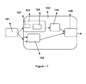
Figure 7 is an embodiment of a device for up-sampling low-resolution depth data according to the present invention. - The reference numbers as used in figures may possess the following meanings;
Nearest neighbour up sample (10) Bound detection (20) Adaptive support region filtering (30) 3D content supplier (101) 3D processing unit (102) Depth estimator unit (103) Stereo matching unit (104) Up sampler (105) Depth based processing unit (106) Down sampler (107) - Hereinafter, the embodiments of the present invention will be described in detail with reference to the attached drawings. The present invention is not restricted to the following embodiments and many variations are possible within the scope of the present invention. The embodiments of the present invention are provided in order to more completely explain examples of the present invention to a person skilled in the art.
- It has to be mentioned that stereo content can be present in various formats and can be supplied through various sources, which can provide video scenes of digital stereo video, digital stereo images, scanned film print stereo frames through a broadcast live system in real time or storage medium such as a hard-disk, scanner, optical disk or the like.
- With respect to
Figures 1 to 6 , a method of up-sampling low-resolution depth data according to the invention is explained, wherein the low-resolution depth data can be in the form of a disparity map obtained through stereo image processing or in the form of a range map obtained by active sensors. According to the principle of the invention, the low-resolution depth data are combined with corresponding high-resolution colour data of the same scene to provide high-resolution depth data with improved precision achieved by the depth data up-sampling according to the invention. Thus, the high-resolution depth map received by the method of depth data up-sampling according to the invention can be used for virtual view synthesis, depth-based enhancement or related 3D applications for 3D televisions or similar 3D applications in computers, beamers or the like for viewing 3D movies or other 3D content by consumers. - When the low-resolution depth data are in form of a disparity map, the estimated disparity map is self-registered with one of the stereo images. When the low-resolution depth data is in the form of a range map, however, a registration is required between colour data and depth data, which can be achieved by homograph mapping. According to the invention it is assumed that the depth data and the colour data are registered.
-
Figure 1 shows the method according to the present invention of up-sampling low-resolution disparity depth maps by exploiting high-resolution colour images of the same scene in two steps. In particular, in a first procedure the low-resolution disparity map is up-sampled using a nearest neighbour-interpolation (10). In the second procedure, the high resolution colour image of the same scene as with respect to the first procedure is used to detect the vertical and horizontal bounds (20), which will be explained in more detail. Once the vertical and horizontal bounds are determined, an averaging filter is applied among the arbitrary shaped region by the utilization of horizontal and vertical integral data of the disparity map so that adaptive support region filtering (30) leads to the high-resolution disparity map. - In particular, the second procedure involves detecting of adaptive shaped regions for each pixel defining colour-wise similar pixel groups in the high-resolution colour image which is achieved by vertical and horizontal bound search which limits the colour variation within. During bound search, neighbouring pixel bounds are necessary to decrease the computational complexity. Once the vertical and horizontal bounds are determined, the averaging filter is applied among the arbitrary shaped region by the utilization of horizontal and vertical integral data of the disparity map, wherein integral data enable the fast computation which is independent from an increase in window sizes. The averaging operation within colour-wise similar pixel groups provide crisp, especially at object boundaries, and smooth high-resolution depth data wherein erroneous regions are also corrected in some manner.
- It is the advantage of the method according to the invention in view of the known joint bilateral up-sampling algorithms that the computational complexity can be reduced by utilization of summed area tables wherein a higher precision is achieved at object boundaries due to connected support regions.
- In the following, the present invention is explained in more detail with respect to
Figures 2 to 6 . - It is a further disadvantage of the prior art that during up-sampling of low resolution disparity maps by fixed coefficient filters, such as bicubic and bilinear, the disparity edges do not correspond to colour edges, which causes artifacts at object boundaries and does not provide correction of wrong disparity assignments. However, the up sampling should preserve edge information as well as smooth disparity map at un-textured regions, providing disparity correction. In that manner, the present invention first up scales the low resolution disparity map to the original high resolution image size by widely utilized nearest neighbour interpolation, as given in equation (B). In (B), HighDisp and LowDisp correspond to high and low resolution disparity maps, SH and SV correspond to the horizontal and vertical scaling factor between two resolutions. The disparity values are also scaled by the horizontal scaling factor, since disparity is defined among horizontal axis and is directly related to the width of the stereo frames.

- The scaling in equation (B) is unsuitable to provide high precision up sampled disparity map. Therefore, adaptive support region filtering operation is performed to refine the disparity map. According to an adaptive support region the idea can be used to estimate disparity maps between stereo pairs.
- However, the present invention exploits the adaptive support region idea for up sampling and smoothing low resolution disparity maps according to the high resolution colour image rather than stereo disparity map estimation. Disparity cost values can be aggregated among support regions and the disparity values providing minimum cost is assigned to the pixels. In the present invention, adaptive support region is utilized to filter disparity maps. Adaptive support region for each pixel is determined by detecting vertical and horizontal intensity bounds in the high resolution colour image.
- As given in
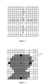
figure 2 , for each pixel a search is performed in four directions (up, down, left and right) to determine the colour wise neighbourhood. In any direction, the search continues until the first pixel whose absolute intensity difference with the centre pixel is above a predetermined threshold is reached, which actually forms the bound in the corresponding direction. Hence, for each pixel four bounds in four directions are determined which define colour wise similar pixel region bounds. This search can be performed for each pixel independently which actually increases computation complexity as the search width increases. However, according to this invention, bound detection is performed in a computationally efficient way by enforcing bounds of the neighbouring pixels during the search for a pixel. As illustrated infigure 3 , before the bound detection of a pixel, the bounds of left (indexed as 1) and upper (indexed as 2) neighbour pixels have been detected in the scan order. The horizontal bound search of the pixel (black circled) starts form the left (L1) and right (R1) bounds of the left neighbouring pixel, if the intensity difference of L1 with the corresponding pixel is below (above) the predefined threshold, search continues in left (right) direction; if the intensity difference of R1 and the centre pixel is below (above) the threshold, search continues in right (left) direction. The same procedure is also followed during the vertical bound detection as well; the bound search in upward direction starts from the upper bound (U2) of the upper neighbouring pixel and the direction is determined according to the intensity difference between U2 and the centre pixel. If the difference is below (above) the threshold, search continues in upward (downward) direction. The bound search in downward direction starts from the lower bound (D2) of the upper neighbouring pixel and the search direction is determined based on the intensity difference. If the absolute difference is below (above) the threshold, search is conducted in downward (upward) direction. Utilization of the bounds of the neighbouring pixels provides a decrease in the search range, which actually saves almost 50% of the computation of the bound search. The idea in this search is logical, since similar coloured neighbouring pixels have close bounds, hence unnecessary search is prevented. - Once the bounds for each pixel in the high resolution colour image are determined (upper bound UB, lower bound DB, left bound LB and right bound RB), the next step involves averaging of disparity values by exploiting the bounds and the disparity maps. The adaptive support region for a pixel is extracted by considering horizontal bounds of the pixels in the vertical bound of the corresponding pixel as illustrated in
figure 4 . This region (3) defines the locally similar coloured pixels around the pixel in an efficient way, and the next step involves an averaging operation of the disparity values within the support region. It is important to note that, calculating the average disparity value among the support region for each pixel requires lots of computation, and as the support region sizes increase, such a process becomes inefficient. Therefore, summed area tables are utilized to perform averaging efficiently and be independent of the region size. Summed area tables or integral images are vital tools for efficient box filtering, whose coefficients are all same i.e., averaging filters. Integral image of an image is obtained by equation (C), where each pixel value involves the sum of the values before that pixel as illustrated infigure 5 , the sum of the pixels (4).
- Once the integral image is calculated, the average values within a box (rectangle) window can be calculated by four addition operation (equation D) independent of the window size.

- The same idea can be exploited for arbitrary support region averaging by orthogonal horizontal and vertical integral images, which actually involve two 1D integration instead of one 2D integration. In that manner, initially the horizontal integral image of the nearest neighbour up scaled disparity map is constructed (equation E), where each row is treated independently and the integral is evaluated among consecutive columns.

- Horizontal integral image of the disparity map can be utilized to determine the sum of disparity values within a closed horizontal bound easily (equation F), hence for each row illustrated in
figure 6 the total disparity value among horizontal bounds are calculated (horizontal gray coloured pixels) and the total disparity value is determined by summation of these values in vertical direction starting from pixel a to pixel b as given in equation (G).

- The vertical summation given in equation (G) can be achieved by integral data as well in order to decrease computational complexity. In that manner, the vertical integral data of the horizontal sum data is obtained via (H),

and the total disparity value within the support region is obtained through one subtraction among the vertical integral data as given in equation (I). Thus, the computational complexity does not depend on the length of the vertical bounds, which enables the utilization of larger neighbourhood increasing the robustness and precision.
- The utilization of vertical and horizontal integral data provides the computation complexity of the averaging filter to be independent of the adaptive region width; in that manner the horizontal and vertical search width could be chosen as large as possible.
- The average disparity value within the adaptive support region is finally calculated by normalizing the total sum with the number of pixels in the region, which is also determined by summing up the width of the horizontal bounds of the pixels located among the vertical bounds of the corresponding pixel, as in equation (J).

- As in the summation of total disparity values within an arbitrary region, vertical and horizontal integral data can be utilized to calculate the area of the arbitrary region for each pixel instead of equation J, which turns out to be computationally burden as the region size increases. In that manner, initially assigning column indexes to the count data (InitCount) forming the horizontal integral data, the horizontal width for each pixel can be calculated by utilizing the horizontal bounds as:

- In equation (K), HorCount gives the width of horizontal bounds for each pixel; in order to calculate the total number of pixels, vertical summation is also required. Hence, vertical integral data is obtained from the horizontal integral data as follows in equation (L):

- Finally, total number of pixels can be found by equation (M) whose computational complexity is insensitive to the area unlike the solution given in equation (1J).

- Disparity assignment is achieved by normalizing the sum of disparity values by the arbitrary region area as in equation N

- It is important to note that, the proposed up sampling method exploits averaging filter among arbitrarily shaped local windows by vertical and horizontal passes. The utilization of summed area tables (integral data) provides the independency of the algorithm to the area of the support region. In that manner, the proposed method is much faster than edge preserving joint bilateral up sampling, which is actually a widely utilized algorithm. Moreover, during the detection of region bounds utilizing neighbouring relations between pixels tremendously decreases computational complexity of the algorithm. The presented invention provides connected support regions for each pixel, having a compact relation which is not the case in bilateral up-sampling and increasing precision.
- In the following, an embodiment is described, wherein the method of the invention is a combination of eight steps.
- Step 1: Up scale the low resolution input depth map to the desired resolution by nearest neighbour interpolation.
- Step 2: Detect the horizontal and vertical bounds of each pixel on the high resolution colour image depending on the intensity differences. In order to decrease computation complexity, exploit bounds of neighbouring pixels to start the bound search. Thus, right bound RB, left bound LB, upper bound UB and lower bound DB are detected for each pixel.
- Step 3: Obtain the horizontal integral disparity map by utilizing the following formula (E) for each row independently.

- Step 4: For each pixel, calculate the sum of disparity values among horizontal direction by utilizing the horizontal integral image and the horizontal (left and right LB, RB) bounds.

- Step 5: Obtain the vertical integral of the horizontally summed disparity map by integrating over each column independently.

- Step 6: For each pixel, calculate the total disparity values among the arbitrary support region by one subtraction of lower and upper bounds over the vertical integral data extracted in step 5.

- Step 7: Calculate the total area of the arbitrary support region for each pixel by vertical and horizontal integral data. First, form the horizontal integral, and calculate horizontal bound widths for each pixel; then form the vertical integral data of the horizontal bounds.
- Finally, calculate the vertical summation of the horizontal width data by utilizing the vertical bounds, which gives the area of the arbitrary regions for each pixel.


- Step 8: The final disparity value for each pixel is obtained by normalizing the sum value determined in step 6 by support area calculated in step 7.

- With respect to
Figure 7 , a depth data up-sampler device is explained in the following. - Depth Data Upsampler is a device that increases the resolution of depth data depending on the high resolution colour image. Depth data correspond to 3D structure that can be obtained through a stereo (multi-view) depth estimator or active sensors (IR or laser) that exploit time-of-flight. Thus, the 3D content supplier (101) provides digital stereo (multi-view) video, images, scanned film print stereo (multi-view) frames or colour and its measured low resolution depth data to a 3D processing unit (102). The 3D stereo or multi-view content can be provided through a broadcast live system, or from a stored medium, wherein the colour plus depth can be provided through an active sensor involving IR or laser transmitter and receiver capturing depth data and a camera capturing colour data.
- The 3D processing unit (102) is a device that exploits 3D data for several applications, in that manner the unit (102) can be a part of a 3D TV system, a computer specialised for 3D applications or a processor embedded on active sensors to provide processed depth data.
- Depending on the type of the input data, 3D processing unit (102) may involve a depth estimator unit (103) for stereo or multi-view content, involves a depth upsampler unit (105) and a depth based processing unit (106). For stereo or multi-view content, depth data is required to be extracted; in that manner, depth estimator unit (103) is specialised for estimating 3D structure. In depth estimator unit (103), a down sampler unit (107) is required to decrease the resolution of the input data so that fast processing can be achieved especially for real-time systems of 3D TVs. The downsampling shrinks the number of depth hypotheses and number of pixels in the images, enabling low computational complexity. This unit is followed by a stereo (multi-view) depth estimator or matching unit (104) that extracts 3D structure by pixel matching. Exploiting down sampled data, the output of depth estimator (104) is low resolution depth map(s) of stereo or multi-view frames. In most cases, low resolution depth data is required to be up sampled especially for depth based applications in 3D TVs and computers. The depth data provided from active sensors is also low resolution and up sampling is vital for various applications such as virtual view synthesis. The invention refers in particular to a depth up-sampling device (105) and the corresponding method, which are important for 3D processing units in almost every application. Depth up-sampling device (105) gets two inputs, low resolution depth data and the corresponding high resolution colour view. For stereo or multi-view case, depth data can belong to any of the views and its colour data is available; for the colour plus depth case, both are provided through a capturing device or 3D content supplier (101). Depth up-sampling device (105) outputs high resolution depth data for the corresponding high resolution colour view by following the steps explained in
Figure 1 . The high resolution depth data can be used by another unit in the 3D processing unit (102). The depth-based processing unit (106) is a module performing any depth driven application involving virtual view synthesis, on scene display embedding, depth based enhancement. Depending on the type of the 3D processing unit, depth-based processing unit (106) may show variation. For example, for 3D TVs, depth-based processing unit (106) may involve adaptive depth adjustment via virtual view synthesis or depth based enhancement. For a computer providing high resolution depth data may be sufficient or virtual tour within the 3D content can be achieved by virtual view synthesis. For an embedded processor on an active sensor, providing high resolution depth data can be sufficient. - In summary, the present invention provides a method and a device for up-sampling low resolution depth data of a video sequence to higher resolution. In particular, the invention provides the ability for systems estimating depth maps to process at lower resolutions so that the computational complexity is reduced wherein the estimated depth maps are up-sampled to the original video resolution. In addition, the registration of low resolution depth information gathered from active sensors to high resolution colour image is also provided.
- The up-sampling method according to the invention is basically achieved by up-scaling low resolution depth data to the desired resolution via well known nearest neighbour interpolation which do not preserve colour and depth edges. The method of the invention further involves detection of adaptive shaped regions for each pixel defining colour wise similar pixel groups in the high resolution colour image, which is achieved by vertical and horizontal bound search which limits the colour variation within. During bound search, neighbouring pixel bounds are constrained in order to decrease computational complexity. Once the vertical and horizontal bounds are determined, an averaging filter is applied among the arbitrary shaped region by the utilization of horizontal and vertical integral data of the disparity map. Integral data enable fast computation insensitive to increase in window sizes. The averaging operation within colour wise similar pixel groups provide crisp, especially at object boundaries, and smooth high resolution depth data, where erroneous regions are also corrected in some manner. The advantage of the proposed method over well known joint bilateral up sampling algorithm is the lower computational complexity by the utilization of summed area tables and higher precision at object boundaries due to connected support region. The invention can be extended to extraction of depth (disparity) for videos captured through multiple cameras in addition to stereo by analysing images pair wise.
Claims (10)
- Method of processing three-dimensional image data by up-sampling low resolution depth data, in particular in the form of a range map or a disparity map of stereo content, such as digital stereo video, digital images, scanned film print stereo frames through a broadcast live system in real time or through a storage medium such as a hard disk, scanner, optical disk or the like, comprising the following successive steps:- up-scaling the low resolution depth data to the desired resolution using a nearest neighbour interpolation to receive an up-scaled disparity map,- detecting the horizontal and vertical bounds of each pixel of a high resolution colour image based on intensity differences, wherein the low resolution depth data correspond to the high resolution colour image,- combining the up-scaled disparity map and the detected vertical and horizontal bounds by applying an averaging filter among an arbitrary shaped region by the utilization of horizontal and vertical integral data of the up-scaled disparity map to receive a high resolution disparity map.
- Method according to claim 1, characterized in that the averaging filter performs a filtering among the nearest neighbour up-scaled disparity map by utilizing adaptive support windows detected through processing of the high resolution colour images, wherein the adaptive support windows are determined by detecting the vertical and horizontal bounds for each pixel having an intensity range within a threshold, wherein then for each pixel the averaging of the disparity values among the detected bounds of the neighbouring pixels located within the bounds of the corresponding pixels is performed.
- Method according to claim 1 or 2, characterized in that the averaging of the disparity values is performed by the utilization of summed area tables of the nearest neighbour up-scaled disparity map in horizontal and vertical direction.
- Method according to one of the preceding claims, wherein the horizontal integral image of the nearest neighbour up-scaled disparity map is calculated by the equation

wherein each row is treated independently and the integral is evaluated among consecutive columns, and wherein for each pixel the sum of disparity values in horizontal direction is calculated by utilizing the horizontal integral image and the horizontal bounds according to the following equation:
wherein LB are the left bounds and RB are the right bounds. - Method according to one of the preceding claims, wherein the vertical integral of the horizontally summed disparity map is obtained by integrating over each column independently by the following equation:

wherein the total disparity values are calculated for each pixel among the arbitrary support region by a subtraction of lower and upper bounds over the vertical integral data resulting in Sum(x,y),
wherein the total area of the arbitrary support region for each pixel Area(x,y) is calculated by vertical and horizontal integral data,
and wherein the final disparity value for each pixel is calculated by normalising the sum value Sum(x,y) by the support area Area(x,y) by the equation
- Device for processing three-dimensional image data by up-sampling low resolution depth data, in particular in particular in the form of a range map or a disparity map of stereo content, such as digital stereo video, digital images, scanned film print stereo frames through a broadcast live system in real time or through a storage medium such as a hard disk, scanner, optical disk or the like, comprising- a depth estimator unit (103) which provides the low resolution depth data,- a depth up-sampling unit (105) which combines the low resolution depth data of the depth estimator unit (103) and corresponding high resolution colour data to process a high resolution disparity map, wherein the low resolution depth data are up-scaled to the desired resolution using a nearest neighbour interpolation to receive an up-scaled disparity map,wherein the horizontal and vertical bounds of each pixel of a high resolution colour image based on intensity differences are detected, wherein the low resolution depth data correspond to the high resolution colour image, and wherein the up-scaled disparity map and the detected vertical and horizontal bounds are combined by applying an averaging filter among an arbitrary shaped region by the utilization of horizontal and vertical integral data of the up-scaled disparity map to receive the high resolution disparity map.
- Device according to claim 6, characterized in that the averaging filter performs a filtering among the nearest neighbour up-scaled disparity map by utilizing adaptive support windows detected through processing of the high resolution colour images, wherein the adaptive support windows are determined by detecting the vertical and horizontal bounds for each pixel having an intensity range within a threshold, wherein then for each pixel the averaging of the disparity values among the detected bounds of the neighbouring pixels located within the bounds of the corresponding pixels is performed.
- Device according to claim 6 or 7, characterized in that the averaging of the disparity values is performed by the utilization of summed area tables of the nearest neighbour up-scaled disparity map in horizontal and vertical direction.
- Device according to any of claims 6 to 8, wherein the horizontal integral image of the nearest neighbour up-scaled disparity map is calculated by the equation

wherein each row is treated independently and the integral is evaluated among consecutive columns, and wherein for each pixel the sum of disparity values in horizontal direction is calculated by utilizing the horizontal integral image and the horizontal bounds according to the following equation:
wherein LB are the left bounds and RB are the right bounds. - Device according to any of claims 6 to 9, wherein the vertical integral of the horizontally summed disparity map is obtained by integrating over each column independently by the following equation:

wherein the total disparity values are calculated for each pixel among the arbitrary support region by a subtraction of lower and upper bounds over the vertical integral data resulting in Sum(x,y),
wherein the total area of the arbitrary support region for each pixel Area(x,y) is calculated by vertical and horizontal integral data,
and wherein the final disparity value for each pixel is calculated by normalising the sum value Sum(x,y) by the support area Area(x,y) by the equation
Applications Claiming Priority (1)
| Application Number | Priority Date | Filing Date | Title |
|---|---|---|---|
| TR2010/10439A TR201010439A2 (en) | 2010-12-14 | 2010-12-14 | Up-sampling of depth data |
Publications (3)
| Publication Number | Publication Date |
|---|---|
| EP2466901A2 true EP2466901A2 (en) | 2012-06-20 |
| EP2466901A3 EP2466901A3 (en) | 2013-09-04 |
| EP2466901B1 EP2466901B1 (en) | 2017-06-14 |
Family
ID=45065822
Family Applications (1)
| Application Number | Title | Priority Date | Filing Date |
|---|---|---|---|
| EP11191976.7A Active EP2466901B1 (en) | 2010-12-14 | 2011-12-05 | Depth data upsampling |
Country Status (3)
| Country | Link |
|---|---|
| EP (1) | EP2466901B1 (en) |
| ES (1) | ES2638896T3 (en) |
| TR (1) | TR201010439A2 (en) |
Cited By (9)
| Publication number | Priority date | Publication date | Assignee | Title |
|---|---|---|---|---|
| CN102819837A (en) * | 2012-07-12 | 2012-12-12 | 清华大学 | Method and device for depth map processing based on feedback control |
| CN103049914A (en) * | 2012-12-19 | 2013-04-17 | 香港应用科技研究院有限公司 | Boundary-based high-resolution depth map generation |
| US20130266211A1 (en) * | 2012-04-06 | 2013-10-10 | Brigham Young University | Stereo vision apparatus and method |
| US9076236B2 (en) | 2013-09-12 | 2015-07-07 | At&T Intellectual Property I, L.P. | Guided image upsampling using bitmap tracing |
| AU2014218390B2 (en) * | 2014-08-27 | 2017-01-12 | Canon Kabushiki Kaisha | Method, system and apparatus for forming a high resolution depth map |
| US9761000B2 (en) | 2015-09-18 | 2017-09-12 | Qualcomm Incorporated | Systems and methods for non-obstacle area detection |
| JP2018066701A (en) * | 2016-10-21 | 2018-04-26 | ソニーセミコンダクタソリューションズ株式会社 | Distance measurement device and method for controlling distance measurement device |
| US9998725B2 (en) | 2015-10-05 | 2018-06-12 | Electronics And Telecommunications Research Institute | Apparatus and method for generating depth information |
| US10362296B2 (en) | 2017-08-17 | 2019-07-23 | Microsoft Technology Licensing, Llc | Localized depth map generation |
Citations (1)
| Publication number | Priority date | Publication date | Assignee | Title |
|---|---|---|---|---|
| US20080267494A1 (en) | 2007-04-30 | 2008-10-30 | Microsoft Corporation | Joint bilateral upsampling |
Family Cites Families (1)
| Publication number | Priority date | Publication date | Assignee | Title |
|---|---|---|---|---|
| KR101502365B1 (en) * | 2008-11-06 | 2015-03-13 | 삼성전자주식회사 | Three-dimensional image generator and control method thereof |
-
2010
- 2010-12-14 TR TR2010/10439A patent/TR201010439A2/en unknown
-
2011
- 2011-12-05 EP EP11191976.7A patent/EP2466901B1/en active Active
- 2011-12-05 ES ES11191976.7T patent/ES2638896T3/en active Active
Patent Citations (1)
| Publication number | Priority date | Publication date | Assignee | Title |
|---|---|---|---|---|
| US20080267494A1 (en) | 2007-04-30 | 2008-10-30 | Microsoft Corporation | Joint bilateral upsampling |
Cited By (20)
| Publication number | Priority date | Publication date | Assignee | Title |
|---|---|---|---|---|
| US20130266211A1 (en) * | 2012-04-06 | 2013-10-10 | Brigham Young University | Stereo vision apparatus and method |
| US9317923B2 (en) * | 2012-04-06 | 2016-04-19 | Brigham Young University | Stereo vision apparatus and method |
| CN102819837A (en) * | 2012-07-12 | 2012-12-12 | 清华大学 | Method and device for depth map processing based on feedback control |
| CN102819837B (en) * | 2012-07-12 | 2015-02-18 | 清华大学 | Method and device for depth map processing based on feedback control |
| CN103049914A (en) * | 2012-12-19 | 2013-04-17 | 香港应用科技研究院有限公司 | Boundary-based high-resolution depth map generation |
| US8891905B2 (en) | 2012-12-19 | 2014-11-18 | Hong Kong Applied Science And Technology Research Institute Co., Ltd. | Boundary-based high resolution depth mapping |
| CN103049914B (en) * | 2012-12-19 | 2016-03-16 | 香港应用科技研究院有限公司 | High-resolution depth map generation method and system based on boundary |
| US9076236B2 (en) | 2013-09-12 | 2015-07-07 | At&T Intellectual Property I, L.P. | Guided image upsampling using bitmap tracing |
| US9491472B2 (en) | 2013-09-12 | 2016-11-08 | At&T Intellectual Property I, L.P. | Guided image upsampling using bitmap tracing |
| US10402941B2 (en) | 2013-09-12 | 2019-09-03 | At&T Intellectual Property I, L.P. | Guided image upsampling using bitmap tracing |
| US9589319B2 (en) | 2014-08-27 | 2017-03-07 | Canon Kabushiki Kaisha | Method, system and apparatus for forming a high resolution depth map |
| AU2014218390B2 (en) * | 2014-08-27 | 2017-01-12 | Canon Kabushiki Kaisha | Method, system and apparatus for forming a high resolution depth map |
| US9761000B2 (en) | 2015-09-18 | 2017-09-12 | Qualcomm Incorporated | Systems and methods for non-obstacle area detection |
| US9905015B2 (en) | 2015-09-18 | 2018-02-27 | Qualcomm Incorporated | Systems and methods for non-obstacle area detection |
| US10395377B2 (en) | 2015-09-18 | 2019-08-27 | Qualcomm Incorporated | Systems and methods for non-obstacle area detection |
| US9998725B2 (en) | 2015-10-05 | 2018-06-12 | Electronics And Telecommunications Research Institute | Apparatus and method for generating depth information |
| JP2018066701A (en) * | 2016-10-21 | 2018-04-26 | ソニーセミコンダクタソリューションズ株式会社 | Distance measurement device and method for controlling distance measurement device |
| WO2018074085A1 (en) * | 2016-10-21 | 2018-04-26 | ソニーセミコンダクタソリューションズ株式会社 | Rangefinder and rangefinder control method |
| US11454723B2 (en) | 2016-10-21 | 2022-09-27 | Sony Semiconductor Solutions Corporation | Distance measuring device and distance measuring device control method |
| US10362296B2 (en) | 2017-08-17 | 2019-07-23 | Microsoft Technology Licensing, Llc | Localized depth map generation |
Also Published As
| Publication number | Publication date |
|---|---|
| ES2638896T3 (en) | 2017-10-24 |
| EP2466901B1 (en) | 2017-06-14 |
| EP2466901A3 (en) | 2013-09-04 |
| TR201010439A2 (en) | 2012-07-23 |
Similar Documents
| Publication | Publication Date | Title |
|---|---|---|
| EP2466901B1 (en) | Depth data upsampling | |
| US8780172B2 (en) | Depth and video co-processing | |
| Kang et al. | A context-adaptive SPN predictor for trustworthy source camera identification | |
| EP2209087B1 (en) | Apparatus and method of obtaining high-resolution image | |
| Yang et al. | Depth recovery using an adaptive color-guided auto-regressive model | |
| US11062464B2 (en) | Image processing apparatus, method, and storage medium to derive optical flow | |
| WO2019133922A1 (en) | Point cloud denoising systems and methods | |
| US10841558B2 (en) | Aligning two images by matching their feature points | |
| US20230127009A1 (en) | Joint objects image signal processing in temporal domain | |
| US20140072232A1 (en) | Super-resolution method and apparatus for video image | |
| WO2019222364A1 (en) | Panoramic image construction based on images captured by rotating imager | |
| US20140169701A1 (en) | Boundary-based high resolution depth mapping | |
| Hua et al. | Extended guided filtering for depth map upsampling | |
| EP2530642A1 (en) | Method of cropping a 3D content | |
| CN117456376A (en) | A remote sensing satellite image target detection method based on deep learning | |
| CN112508832A (en) | Object-oriented remote sensing image data space-time fusion method, system and equipment | |
| EP2466903B1 (en) | A method and device for disparity range detection | |
| KR101262164B1 (en) | Method for generating high resolution depth image from low resolution depth image, and medium recording the same | |
| CN113269696B (en) | Method for denoising image, electronic device, and medium | |
| CN101547323B (en) | Image conversion method, device and display system | |
| Yang et al. | Depth map reconstruction and rectification through coding parameters for mobile 3D video system | |
| Yu et al. | Continuous digital zooming of asymmetric dual camera images using registration and variational image restoration | |
| TW201322732A (en) | Method for adjusting moving depths of video | |
| JP2005339535A (en) | Calculation of dissimilarity measure | |
| CN121305060B (en) | A method and system for real-time alignment of visible and infrared images taken by drones |
Legal Events
| Date | Code | Title | Description |
|---|---|---|---|
| PUAI | Public reference made under article 153(3) epc to a published international application that has entered the european phase |
Free format text: ORIGINAL CODE: 0009012 |
|
| AK | Designated contracting states |
Kind code of ref document: A2 Designated state(s): AL AT BE BG CH CY CZ DE DK EE ES FI FR GB GR HR HU IE IS IT LI LT LU LV MC MK MT NL NO PL PT RO RS SE SI SK SM TR |
|
| AX | Request for extension of the european patent |
Extension state: BA ME |
|
| PUAL | Search report despatched |
Free format text: ORIGINAL CODE: 0009013 |
|
| AK | Designated contracting states |
Kind code of ref document: A3 Designated state(s): AL AT BE BG CH CY CZ DE DK EE ES FI FR GB GR HR HU IE IS IT LI LT LU LV MC MK MT NL NO PL PT RO RS SE SI SK SM TR |
|
| AX | Request for extension of the european patent |
Extension state: BA ME |
|
| RIC1 | Information provided on ipc code assigned before grant |
Ipc: H04N 13/00 20060101AFI20130726BHEP |
|
| 17P | Request for examination filed |
Effective date: 20140304 |
|
| 17Q | First examination report despatched |
Effective date: 20151103 |
|
| GRAP | Despatch of communication of intention to grant a patent |
Free format text: ORIGINAL CODE: EPIDOSNIGR1 |
|
| INTG | Intention to grant announced |
Effective date: 20170105 |
|
| GRAS | Grant fee paid |
Free format text: ORIGINAL CODE: EPIDOSNIGR3 |
|
| GRAA | (expected) grant |
Free format text: ORIGINAL CODE: 0009210 |
|
| AK | Designated contracting states |
Kind code of ref document: B1 Designated state(s): AL AT BE BG CH CY CZ DE DK EE ES FI FR GB GR HR HU IE IS IT LI LT LU LV MC MK MT NL NO PL PT RO RS SE SI SK SM TR |
|
| REG | Reference to a national code |
Ref country code: GB Ref legal event code: FG4D |
|
| REG | Reference to a national code |
Ref country code: CH Ref legal event code: EP Ref country code: AT Ref legal event code: REF Ref document number: 901966 Country of ref document: AT Kind code of ref document: T Effective date: 20170615 |
|
| REG | Reference to a national code |
Ref country code: IE Ref legal event code: FG4D |
|
| REG | Reference to a national code |
Ref country code: DE Ref legal event code: R096 Ref document number: 602011038670 Country of ref document: DE |
|
| REG | Reference to a national code |
Ref country code: NL Ref legal event code: MP Effective date: 20170614 |
|
| REG | Reference to a national code |
Ref country code: ES Ref legal event code: FG2A Ref document number: 2638896 Country of ref document: ES Kind code of ref document: T3 Effective date: 20171024 |
|
| REG | Reference to a national code |
Ref country code: LT Ref legal event code: MG4D |
|
| PG25 | Lapsed in a contracting state [announced via postgrant information from national office to epo] |
Ref country code: LT Free format text: LAPSE BECAUSE OF FAILURE TO SUBMIT A TRANSLATION OF THE DESCRIPTION OR TO PAY THE FEE WITHIN THE PRESCRIBED TIME-LIMIT Effective date: 20170614 Ref country code: GR Free format text: LAPSE BECAUSE OF FAILURE TO SUBMIT A TRANSLATION OF THE DESCRIPTION OR TO PAY THE FEE WITHIN THE PRESCRIBED TIME-LIMIT Effective date: 20170915 Ref country code: NO Free format text: LAPSE BECAUSE OF FAILURE TO SUBMIT A TRANSLATION OF THE DESCRIPTION OR TO PAY THE FEE WITHIN THE PRESCRIBED TIME-LIMIT Effective date: 20170914 Ref country code: HR Free format text: LAPSE BECAUSE OF FAILURE TO SUBMIT A TRANSLATION OF THE DESCRIPTION OR TO PAY THE FEE WITHIN THE PRESCRIBED TIME-LIMIT Effective date: 20170614 Ref country code: FI Free format text: LAPSE BECAUSE OF FAILURE TO SUBMIT A TRANSLATION OF THE DESCRIPTION OR TO PAY THE FEE WITHIN THE PRESCRIBED TIME-LIMIT Effective date: 20170614 |
|
| REG | Reference to a national code |
Ref country code: AT Ref legal event code: MK05 Ref document number: 901966 Country of ref document: AT Kind code of ref document: T Effective date: 20170614 |
|
| REG | Reference to a national code |
Ref country code: FR Ref legal event code: PLFP Year of fee payment: 7 |
|
| PG25 | Lapsed in a contracting state [announced via postgrant information from national office to epo] |
Ref country code: RS Free format text: LAPSE BECAUSE OF FAILURE TO SUBMIT A TRANSLATION OF THE DESCRIPTION OR TO PAY THE FEE WITHIN THE PRESCRIBED TIME-LIMIT Effective date: 20170614 Ref country code: NL Free format text: LAPSE BECAUSE OF FAILURE TO SUBMIT A TRANSLATION OF THE DESCRIPTION OR TO PAY THE FEE WITHIN THE PRESCRIBED TIME-LIMIT Effective date: 20170614 Ref country code: SE Free format text: LAPSE BECAUSE OF FAILURE TO SUBMIT A TRANSLATION OF THE DESCRIPTION OR TO PAY THE FEE WITHIN THE PRESCRIBED TIME-LIMIT Effective date: 20170614 Ref country code: BG Free format text: LAPSE BECAUSE OF FAILURE TO SUBMIT A TRANSLATION OF THE DESCRIPTION OR TO PAY THE FEE WITHIN THE PRESCRIBED TIME-LIMIT Effective date: 20170914 Ref country code: LV Free format text: LAPSE BECAUSE OF FAILURE TO SUBMIT A TRANSLATION OF THE DESCRIPTION OR TO PAY THE FEE WITHIN THE PRESCRIBED TIME-LIMIT Effective date: 20170614 |
|
| PG25 | Lapsed in a contracting state [announced via postgrant information from national office to epo] |
Ref country code: RO Free format text: LAPSE BECAUSE OF FAILURE TO SUBMIT A TRANSLATION OF THE DESCRIPTION OR TO PAY THE FEE WITHIN THE PRESCRIBED TIME-LIMIT Effective date: 20170614 Ref country code: EE Free format text: LAPSE BECAUSE OF FAILURE TO SUBMIT A TRANSLATION OF THE DESCRIPTION OR TO PAY THE FEE WITHIN THE PRESCRIBED TIME-LIMIT Effective date: 20170614 Ref country code: SK Free format text: LAPSE BECAUSE OF FAILURE TO SUBMIT A TRANSLATION OF THE DESCRIPTION OR TO PAY THE FEE WITHIN THE PRESCRIBED TIME-LIMIT Effective date: 20170614 Ref country code: CZ Free format text: LAPSE BECAUSE OF FAILURE TO SUBMIT A TRANSLATION OF THE DESCRIPTION OR TO PAY THE FEE WITHIN THE PRESCRIBED TIME-LIMIT Effective date: 20170614 Ref country code: AT Free format text: LAPSE BECAUSE OF FAILURE TO SUBMIT A TRANSLATION OF THE DESCRIPTION OR TO PAY THE FEE WITHIN THE PRESCRIBED TIME-LIMIT Effective date: 20170614 |
|
| PG25 | Lapsed in a contracting state [announced via postgrant information from national office to epo] |
Ref country code: SM Free format text: LAPSE BECAUSE OF FAILURE TO SUBMIT A TRANSLATION OF THE DESCRIPTION OR TO PAY THE FEE WITHIN THE PRESCRIBED TIME-LIMIT Effective date: 20170614 Ref country code: IS Free format text: LAPSE BECAUSE OF FAILURE TO SUBMIT A TRANSLATION OF THE DESCRIPTION OR TO PAY THE FEE WITHIN THE PRESCRIBED TIME-LIMIT Effective date: 20171014 Ref country code: PL Free format text: LAPSE BECAUSE OF FAILURE TO SUBMIT A TRANSLATION OF THE DESCRIPTION OR TO PAY THE FEE WITHIN THE PRESCRIBED TIME-LIMIT Effective date: 20170614 |
|
| REG | Reference to a national code |
Ref country code: DE Ref legal event code: R097 Ref document number: 602011038670 Country of ref document: DE |
|
| PLBE | No opposition filed within time limit |
Free format text: ORIGINAL CODE: 0009261 |
|
| STAA | Information on the status of an ep patent application or granted ep patent |
Free format text: STATUS: NO OPPOSITION FILED WITHIN TIME LIMIT |
|
| PG25 | Lapsed in a contracting state [announced via postgrant information from national office to epo] |
Ref country code: DK Free format text: LAPSE BECAUSE OF FAILURE TO SUBMIT A TRANSLATION OF THE DESCRIPTION OR TO PAY THE FEE WITHIN THE PRESCRIBED TIME-LIMIT Effective date: 20170614 |
|
| 26N | No opposition filed |
Effective date: 20180315 |
|
| REG | Reference to a national code |
Ref country code: CH Ref legal event code: PL |
|
| PG25 | Lapsed in a contracting state [announced via postgrant information from national office to epo] |
Ref country code: SI Free format text: LAPSE BECAUSE OF FAILURE TO SUBMIT A TRANSLATION OF THE DESCRIPTION OR TO PAY THE FEE WITHIN THE PRESCRIBED TIME-LIMIT Effective date: 20170614 |
|
| REG | Reference to a national code |
Ref country code: IE Ref legal event code: MM4A |
|
| PG25 | Lapsed in a contracting state [announced via postgrant information from national office to epo] |
Ref country code: MT Free format text: LAPSE BECAUSE OF NON-PAYMENT OF DUE FEES Effective date: 20171205 Ref country code: LU Free format text: LAPSE BECAUSE OF NON-PAYMENT OF DUE FEES Effective date: 20171205 |
|
| REG | Reference to a national code |
Ref country code: BE Ref legal event code: MM Effective date: 20171231 |
|
| PG25 | Lapsed in a contracting state [announced via postgrant information from national office to epo] |
Ref country code: IE Free format text: LAPSE BECAUSE OF NON-PAYMENT OF DUE FEES Effective date: 20171205 |
|
| PG25 | Lapsed in a contracting state [announced via postgrant information from national office to epo] |
Ref country code: CH Free format text: LAPSE BECAUSE OF NON-PAYMENT OF DUE FEES Effective date: 20171231 Ref country code: BE Free format text: LAPSE BECAUSE OF NON-PAYMENT OF DUE FEES Effective date: 20171231 Ref country code: LI Free format text: LAPSE BECAUSE OF NON-PAYMENT OF DUE FEES Effective date: 20171231 |
|
| PG25 | Lapsed in a contracting state [announced via postgrant information from national office to epo] |
Ref country code: HU Free format text: LAPSE BECAUSE OF FAILURE TO SUBMIT A TRANSLATION OF THE DESCRIPTION OR TO PAY THE FEE WITHIN THE PRESCRIBED TIME-LIMIT; INVALID AB INITIO Effective date: 20111205 Ref country code: MC Free format text: LAPSE BECAUSE OF FAILURE TO SUBMIT A TRANSLATION OF THE DESCRIPTION OR TO PAY THE FEE WITHIN THE PRESCRIBED TIME-LIMIT Effective date: 20170614 |
|
| PG25 | Lapsed in a contracting state [announced via postgrant information from national office to epo] |
Ref country code: CY Free format text: LAPSE BECAUSE OF NON-PAYMENT OF DUE FEES Effective date: 20170614 |
|
| PG25 | Lapsed in a contracting state [announced via postgrant information from national office to epo] |
Ref country code: MK Free format text: LAPSE BECAUSE OF FAILURE TO SUBMIT A TRANSLATION OF THE DESCRIPTION OR TO PAY THE FEE WITHIN THE PRESCRIBED TIME-LIMIT Effective date: 20170614 |
|
| PG25 | Lapsed in a contracting state [announced via postgrant information from national office to epo] |
Ref country code: PT Free format text: LAPSE BECAUSE OF FAILURE TO SUBMIT A TRANSLATION OF THE DESCRIPTION OR TO PAY THE FEE WITHIN THE PRESCRIBED TIME-LIMIT Effective date: 20170614 |
|
| PG25 | Lapsed in a contracting state [announced via postgrant information from national office to epo] |
Ref country code: AL Free format text: LAPSE BECAUSE OF FAILURE TO SUBMIT A TRANSLATION OF THE DESCRIPTION OR TO PAY THE FEE WITHIN THE PRESCRIBED TIME-LIMIT Effective date: 20170614 |
|
| REG | Reference to a national code |
Ref country code: DE Ref legal event code: R082 Ref document number: 602011038670 Country of ref document: DE Representative=s name: LEONHARD, REIMUND, DIPL.-ING., DE Ref country code: DE Ref legal event code: R082 Ref document number: 602011038670 Country of ref document: DE Representative=s name: LEONHARD, REIMUND, DIPL.-ING., ES |
|
| PGFP | Annual fee paid to national office [announced via postgrant information from national office to epo] |
Ref country code: DE Payment date: 20241210 Year of fee payment: 14 |
|
| PGFP | Annual fee paid to national office [announced via postgrant information from national office to epo] |
Ref country code: GB Payment date: 20241224 Year of fee payment: 14 |
|
| PGFP | Annual fee paid to national office [announced via postgrant information from national office to epo] |
Ref country code: FR Payment date: 20241223 Year of fee payment: 14 |
|
| PGFP | Annual fee paid to national office [announced via postgrant information from national office to epo] |
Ref country code: ES Payment date: 20250131 Year of fee payment: 14 |
|
| PGFP | Annual fee paid to national office [announced via postgrant information from national office to epo] |
Ref country code: IT Payment date: 20241227 Year of fee payment: 14 |
|
| PGFP | Annual fee paid to national office [announced via postgrant information from national office to epo] |
Ref country code: TR Payment date: 20251201 Year of fee payment: 15 |