EP2466693A1 - Water-proof connector and method of assembly of water-proof connector - Google Patents
Water-proof connector and method of assembly of water-proof connector Download PDFInfo
- Publication number
- EP2466693A1 EP2466693A1 EP20110193702 EP11193702A EP2466693A1 EP 2466693 A1 EP2466693 A1 EP 2466693A1 EP 20110193702 EP20110193702 EP 20110193702 EP 11193702 A EP11193702 A EP 11193702A EP 2466693 A1 EP2466693 A1 EP 2466693A1
- Authority
- EP
- European Patent Office
- Prior art keywords
- wire seal
- housing
- insertion holes
- boss pins
- water
- Prior art date
- Legal status (The legal status is an assumption and is not a legal conclusion. Google has not performed a legal analysis and makes no representation as to the accuracy of the status listed.)
- Granted
Links
- 238000000034 method Methods 0.000 title claims description 5
- 238000003780 insertion Methods 0.000 claims abstract description 44
- 230000037431 insertion Effects 0.000 claims abstract description 44
- 238000007789 sealing Methods 0.000 claims abstract description 3
- 230000002093 peripheral effect Effects 0.000 description 13
- 229920001971 elastomer Polymers 0.000 description 4
- 239000000463 material Substances 0.000 description 4
- XLYOFNOQVPJJNP-UHFFFAOYSA-N water Substances O XLYOFNOQVPJJNP-UHFFFAOYSA-N 0.000 description 2
- 230000006835 compression Effects 0.000 description 1
- 238000007906 compression Methods 0.000 description 1
- 238000010276 construction Methods 0.000 description 1
- 238000007796 conventional method Methods 0.000 description 1
- 230000007423 decrease Effects 0.000 description 1
- 238000006073 displacement reaction Methods 0.000 description 1
- 239000000806 elastomer Substances 0.000 description 1
- 230000000149 penetrating effect Effects 0.000 description 1
- 229920000642 polymer Polymers 0.000 description 1
- 239000011347 resin Substances 0.000 description 1
- 229920005989 resin Polymers 0.000 description 1
Images



Classifications
-
- H—ELECTRICITY
- H01—ELECTRIC ELEMENTS
- H01R—ELECTRICALLY-CONDUCTIVE CONNECTIONS; STRUCTURAL ASSOCIATIONS OF A PLURALITY OF MUTUALLY-INSULATED ELECTRICAL CONNECTING ELEMENTS; COUPLING DEVICES; CURRENT COLLECTORS
- H01R13/00—Details of coupling devices of the kinds covered by groups H01R12/70 or H01R24/00 - H01R33/00
- H01R13/46—Bases; Cases
- H01R13/52—Dustproof, splashproof, drip-proof, waterproof, or flameproof cases
- H01R13/5205—Sealing means between cable and housing, e.g. grommet
- H01R13/5208—Sealing means between cable and housing, e.g. grommet having at least two cable receiving openings
-
- H—ELECTRICITY
- H01—ELECTRIC ELEMENTS
- H01R—ELECTRICALLY-CONDUCTIVE CONNECTIONS; STRUCTURAL ASSOCIATIONS OF A PLURALITY OF MUTUALLY-INSULATED ELECTRICAL CONNECTING ELEMENTS; COUPLING DEVICES; CURRENT COLLECTORS
- H01R13/00—Details of coupling devices of the kinds covered by groups H01R12/70 or H01R24/00 - H01R33/00
- H01R13/46—Bases; Cases
- H01R13/52—Dustproof, splashproof, drip-proof, waterproof, or flameproof cases
- H01R13/5202—Sealing means between parts of housing or between housing part and a wall, e.g. sealing rings
-
- H—ELECTRICITY
- H01—ELECTRIC ELEMENTS
- H01R—ELECTRICALLY-CONDUCTIVE CONNECTIONS; STRUCTURAL ASSOCIATIONS OF A PLURALITY OF MUTUALLY-INSULATED ELECTRICAL CONNECTING ELEMENTS; COUPLING DEVICES; CURRENT COLLECTORS
- H01R13/00—Details of coupling devices of the kinds covered by groups H01R12/70 or H01R24/00 - H01R33/00
- H01R13/62—Means for facilitating engagement or disengagement of coupling parts or for holding them in engagement
- H01R13/629—Additional means for facilitating engagement or disengagement of coupling parts, e.g. aligning or guiding means, levers, gas pressure electrical locking indicators, manufacturing tolerances
- H01R13/631—Additional means for facilitating engagement or disengagement of coupling parts, e.g. aligning or guiding means, levers, gas pressure electrical locking indicators, manufacturing tolerances for engagement only
-
- H—ELECTRICITY
- H01—ELECTRIC ELEMENTS
- H01R—ELECTRICALLY-CONDUCTIVE CONNECTIONS; STRUCTURAL ASSOCIATIONS OF A PLURALITY OF MUTUALLY-INSULATED ELECTRICAL CONNECTING ELEMENTS; COUPLING DEVICES; CURRENT COLLECTORS
- H01R13/00—Details of coupling devices of the kinds covered by groups H01R12/70 or H01R24/00 - H01R33/00
- H01R13/46—Bases; Cases
- H01R13/52—Dustproof, splashproof, drip-proof, waterproof, or flameproof cases
- H01R13/5219—Sealing means between coupling parts, e.g. interfacial seal
- H01R13/5221—Sealing means between coupling parts, e.g. interfacial seal having cable sealing means
-
- H—ELECTRICITY
- H01—ELECTRIC ELEMENTS
- H01R—ELECTRICALLY-CONDUCTIVE CONNECTIONS; STRUCTURAL ASSOCIATIONS OF A PLURALITY OF MUTUALLY-INSULATED ELECTRICAL CONNECTING ELEMENTS; COUPLING DEVICES; CURRENT COLLECTORS
- H01R43/00—Apparatus or processes specially adapted for manufacturing, assembling, maintaining, or repairing of line connectors or current collectors or for joining electric conductors
- H01R43/005—Apparatus or processes specially adapted for manufacturing, assembling, maintaining, or repairing of line connectors or current collectors or for joining electric conductors for making dustproof, splashproof, drip-proof, waterproof, or flameproof connection, coupling, or casing
Definitions
- the present invention relates to a water-proof connector and a method of assembly of the water-proof connector.
- a known water-proof connector is provided with a member referred to as a wire seal or a collective rubber stopper in a connector housing in order to prevent entry of water or the like from the outside (see Japanese Patent No. 3174261 , for example).
- the wire seal has a plurality of contact insertion holes at positions corresponding to a plurality of cavities in the connector housing. When a contact is inserted into the cavity through the contact insertion hole, the inner periphery of the contact insertion hole comes into intimate contact with an electrical wire connected to the contact to provide waterproofness.
- the connector housing comprises an outer housing and an inner housing. With the water-proof connector, the inner housing is fitted into a recess formed in the outer housing, and the wire seal is interposed between the outer housing and the inner housing.
- the connector housing is made of a resin material
- the wire seal is made of a rubber-based material.
- the wire seal is fixed in the inner housing and positioned with pins with respect to the outer housing. That is, pin-shaped bosses are formed on the outer housing, and recesses into which the bosses are inserted are formed in the wire seal fitted in the inner housing. The wire seal is positioned in the outer housing by inserting the bosses into the recesses of the wire seal.
- the wire seal to be fitted into the inner housing has a predetermined fastening margin in order to ensure sealability between the wire seal and the inner housing. Therefore, when the wire seal is fitted into the inner housing, the wire seal is inwardly compressed and deformed. The compression and deformation of the wire seal may result in a displacement of the recesses formed in the wire seal from the original positions. In this case, the bosses on the outer housing cannot be inserted into the recesses of the wire seal, and the assembly of the water-proof connector fails.
- the outer housing and the inner housing may be forcedly fitted to each other, because the wire seal is made of a rubber-based material.
- the contacts cannot be inserted into the contact insertion holes in the wire seal or are bent, and the connector cannot carry out its function as a connector.
- the present invention has been devised in view of the technical problem described above, and an object of the present invention is to provide a water-proof connector that can be smoothly assembled and can properly carry out its function as a connector, and a method of assembly of the water-proof connector.
- the present invention provides a water-proof connector comprising: a connector housing in which a plurality of cavities into which contacts are accommodated are formed; and a wire seal that has a plurality of contact insertion holes formed at positions corresponding to the cavities and provides sealing by the inner peripheries of the contact insertion holes coming into intimate contact with electrical wires connected to the contacts when the contacts are inserted into the cavities through the contact insertion holes.
- the connector housing comprises: an outer housing having a recess for housing the wire seal; and an inner housing to be fitted into the recess with the wire seal interposed between the outer housing and the inner housing, a plurality of boss pins for positioning the wire seal with respect to the outer housing are formed in the outer housing, and a plurality of pin insertion holes into which the boss pins are inserted are formed in the wire seal.
- boss pins disposed along the outer periphery of the wire seal are tapered from the tip end part toward the base end part so as to have at least a surface facing toward the outer periphery of the wire seal inclined from the inner side of the wire seal toward the outer side.
- boss pins disposed along the outer periphery of the wire seal are tapered at least on the side facing toward the outer periphery of the wire seal as described above, the boss pins can be reliably guided into the pin insertion holes in the wire seal even if the boss pins are misaligned with the pin insertion holes.
- the boss pins disposed along the outer periphery of the wire seal are preferably longer than the other boss pins.
- the present invention provides a method of assembly of a water-proof connector such as that described above comprising: a step of mounting a wire seal on a tip end part of an inner housing; and a step of inserting the inner housing with the wire seal mounted on the tip end part into a recess of an outer housing to insert boss pins into pin insertion holes in the wire seal.
- the boss pins can be reliably guided into the pin insertion holes.
- the water-proof connector can be smoothly assembled and properly carry out its function as a connector.
- a water-proof connector 1 shown in FIGS. 1 to 3 comprises an inner housing 10, a wire seal 30, and an outer housing 50.
- the inner housing 10 has a substantially rectangular parallelepiped shape.
- a plurality of cavities 11 for accommodating contacts (not shown) are formed in the inner housing 10.
- each cavity 11 penetrating the inner housing 10 in the front-rear direction has a housing lance for primarily holding the contact.
- the inner housing 10 has a frontward extending peripheral wall 12 formed along the circumference of the front end of the inner housing 10 facing the outer housing 50.
- the interior of the peripheral wall 12 forms a seal housing recess 13 for housing the wire seal 30.
- the wire seal 30, which is a collective water-proof member, has a substantially plate shape and is configured to be housed in the seal housing recess 13 of the inner housing 10.
- the wire seal 30 is typically made of an elastomer (an elastic polymer) but can be made of any material that provides waterproofness.
- the outer shape and dimensions of the wire seal 30 are designed to ensure intimate contact with the inner peripheral surface of the peripheral wall 12.
- a plurality of ridges 32a, 32b and 32c for improving the contact with the inner peripheral surface of the peripheral wall 12 of the inner housing 10 are formed on the outer peripheral surface of the wire seal 30.
- the wire seal 30 has a plurality of contact insertion holes 31 at positions corresponding to the cavities 11. Electrical wires connected to power contacts accommodated in the cavities 11 are led to the side of the outer housing 50 through the contact insertion holes 31.
- a plurality of ridges 33a, 33b and 33c are formed on the inner periphery of each contact insertion hole 31, and the ridges 33a, 33b and 33c are in intimate contact with the outer peripheral surface of an electrical wire W. As a result, water can be prevented from entering the interior of the inner housing 10 through each contact insertion hole 31.
- the outer housing 50 is mounted to cover the inner housing 10 to prevent the wire seal 30 from dropping off.
- the outer housing 50 has a plurality of electrical wire insertion holes 51 at positions corresponding to the cavities 11.
- the electrical wires W to be connected to the contacts are led to the rear side through the electrical wire insertion holes 51.
- a plurality of boss pins 70 are formed in an outer peripheral part of a region in which the electrical wire insertion holes 51 are formed.
- the plurality of boss pins 70 are provided at intervals along the outer peripheral part of the region in which the electrical wire insertion holes 51 are formed.
- the boss pins 70 may be disposed in the region in which the electrical wire insertion holes 51 are formed.
- the tip end part 70c may have a tapered surface 71 only in the portion facing outward from the region in which the electrical wire insertion holes 51 are formed.
- a tip end part 70d of the boss pin 70B may have a round shape, for example.
- the length of protrusion of the boss pins 70A from the outer housing 50 is greater than the length of protrusion of the boss pins 70B.
- the wire seal 30 has pin insertion holes 80 at positions corresponding to the boss pins 70 of the outer housing 50.
- the boss pins 70A of the boss pins 70 that are disposed along the outer periphery of the region in which the electrical wire insertion holes 51 are formed have the tapered tip end parts 70c. Therefore, in fitting of the wire seal 30 mounted in the inner housing 10 into the outer housing 50, even if the boss pins 70A are misaligned with the pin insertion holes 80 when the tip end parts 70c of the boss pins 70A come into contact with the pin insertion holes 80, the boss pins 70A can be easily guided into the pin insertion holes 80.
- boss pins 70A of the boss pins 70 that are disposed in the outer peripheral part of the region in which the electrical wire insertion holes 51 are formed have a greater length of protrusion, when the wire seal 30 is fitted into the outer housing 50, the tip end parts 70c of the boss pins 70A disposed in the outer peripheral part come into contact with the pin insertion holes 80 earlier than the boss pins 70B disposed in that region. As a result, even if the boss pins 70A and 70B are misaligned with the pin insertion holes 80, the boss pins 70A and 70B can be easily guided into the pin insertion holes 80.
- the wire seal 30 can be reliably assembled into the outer housing 50 at a proper position by smoothly and reliably fitting the boss pins 70 into the pin insertion holes 80.
- the water-proof connector 1 can be smoothly assembled and properly carry out its function as a connector.
Landscapes
- Connector Housings Or Holding Contact Members (AREA)
- Manufacturing Of Electrical Connectors (AREA)
Abstract
Description
- The present invention relates to a water-proof connector and a method of assembly of the water-proof connector.
- A known water-proof connector is provided with a member referred to as a wire seal or a collective rubber stopper in a connector housing in order to prevent entry of water or the like from the outside (see Japanese Patent No.
3174261 - The connector housing comprises an outer housing and an inner housing. With the water-proof connector, the inner housing is fitted into a recess formed in the outer housing, and the wire seal is interposed between the outer housing and the inner housing.
- Typically, the connector housing is made of a resin material, and the wire seal is made of a rubber-based material. In order to align the cavities formed in the outer housing and the inner housing and the contact insertion holes formed in the wire seal with each other, the wire seal is fixed in the inner housing and positioned with pins with respect to the outer housing. That is, pin-shaped bosses are formed on the outer housing, and recesses into which the bosses are inserted are formed in the wire seal fitted in the inner housing. The wire seal is positioned in the outer housing by inserting the bosses into the recesses of the wire seal.
- However, the conventional technique described above has the problem described below.
- In assembly of the water-proof connector, the wire seal to be fitted into the inner housing has a predetermined fastening margin in order to ensure sealability between the wire seal and the inner housing. Therefore, when the wire seal is fitted into the inner housing, the wire seal is inwardly compressed and deformed. The compression and deformation of the wire seal may result in a displacement of the recesses formed in the wire seal from the original positions. In this case, the bosses on the outer housing cannot be inserted into the recesses of the wire seal, and the assembly of the water-proof connector fails.
- Even if the wire seal is not properly positioned in the recess of the outer housing, the outer housing and the inner housing may be forcedly fitted to each other, because the wire seal is made of a rubber-based material. However, in such a case, the contacts cannot be inserted into the contact insertion holes in the wire seal or are bent, and the connector cannot carry out its function as a connector.
- The present invention has been devised in view of the technical problem described above, and an object of the present invention is to provide a water-proof connector that can be smoothly assembled and can properly carry out its function as a connector, and a method of assembly of the water-proof connector.
- To attain the object, the present invention provides a water-proof connector comprising: a connector housing in which a plurality of cavities into which contacts are accommodated are formed; and a wire seal that has a plurality of contact insertion holes formed at positions corresponding to the cavities and provides sealing by the inner peripheries of the contact insertion holes coming into intimate contact with electrical wires connected to the contacts when the contacts are inserted into the cavities through the contact insertion holes. The connector housing comprises: an outer housing having a recess for housing the wire seal; and an inner housing to be fitted into the recess with the wire seal interposed between the outer housing and the inner housing, a plurality of boss pins for positioning the wire seal with respect to the outer housing are formed in the outer housing, and a plurality of pin insertion holes into which the boss pins are inserted are formed in the wire seal. Of the plurality of boss pins, boss pins disposed along the outer periphery of the wire seal are tapered from the tip end part toward the base end part so as to have at least a surface facing toward the outer periphery of the wire seal inclined from the inner side of the wire seal toward the outer side.
- Since the boss pins disposed along the outer periphery of the wire seal are tapered at least on the side facing toward the outer periphery of the wire seal as described above, the boss pins can be reliably guided into the pin insertion holes in the wire seal even if the boss pins are misaligned with the pin insertion holes.
- Of the plurality of boss pins, the boss pins disposed along the outer periphery of the wire seal are preferably longer than the other boss pins.
- Furthermore, the present invention provides a method of assembly of a water-proof connector such as that described above comprising: a step of mounting a wire seal on a tip end part of an inner housing; and a step of inserting the inner housing with the wire seal mounted on the tip end part into a recess of an outer housing to insert boss pins into pin insertion holes in the wire seal.
- According to the present invention, even if the boss pins are misaligned with the pin insertion holes in the wire seal, the boss pins can be reliably guided into the pin insertion holes. As a result, the water-proof connector can be smoothly assembled and properly carry out its function as a connector.
- The present invention will be described with reference to the accompanying drawings, in which:
-
FIG. 1 is an exploded perspective view showing a configuration of a water-proof connector according to an embodiment; -
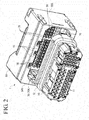
FIG. 2 is an exploded perspective view of the water-proof connector shown inFIG. 1 viewed at a different angle; -
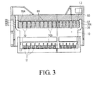
FIG. 3 is a cross-sectional view of the water-proof connector; -
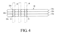
FIG. 4 is a cross-sectional view of a wire seal; -
FIG. 5 is a perspective view of an outer housing; -
FIG. 6 is a cross-sectional view of boss pins formed in the outer housing; and -
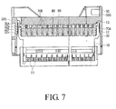
FIG. 7 is a cross-sectional view of the water-proof connector being assembled. - A water-
proof connector 1 shown inFIGS. 1 to 3 comprises aninner housing 10, awire seal 30, and anouter housing 50. - The
inner housing 10 has a substantially rectangular parallelepiped shape. A plurality ofcavities 11 for accommodating contacts (not shown) are formed in theinner housing 10. Although not shown, eachcavity 11 penetrating theinner housing 10 in the front-rear direction has a housing lance for primarily holding the contact. - The
inner housing 10 has a frontward extendingperipheral wall 12 formed along the circumference of the front end of theinner housing 10 facing theouter housing 50. The interior of theperipheral wall 12 forms a seal housing recess 13 for housing thewire seal 30. - The
wire seal 30, which is a collective water-proof member, has a substantially plate shape and is configured to be housed in theseal housing recess 13 of theinner housing 10. Thewire seal 30 is typically made of an elastomer (an elastic polymer) but can be made of any material that provides waterproofness. - The outer shape and dimensions of the
wire seal 30 are designed to ensure intimate contact with the inner peripheral surface of theperipheral wall 12. A plurality ofridges peripheral wall 12 of theinner housing 10 are formed on the outer peripheral surface of thewire seal 30. - The
wire seal 30 has a plurality ofcontact insertion holes 31 at positions corresponding to thecavities 11. Electrical wires connected to power contacts accommodated in thecavities 11 are led to the side of theouter housing 50 through thecontact insertion holes 31. - As shown in
FIG. 4 , a plurality ofridges contact insertion hole 31, and theridges inner housing 10 through eachcontact insertion hole 31. - The
outer housing 50 is mounted to cover theinner housing 10 to prevent thewire seal 30 from dropping off. - The
outer housing 50 has a plurality of electricalwire insertion holes 51 at positions corresponding to thecavities 11. The electrical wires W to be connected to the contacts are led to the rear side through the electricalwire insertion holes 51. - As shown in
FIG. 5 , in theouter housing 50 configured as described above, a plurality ofboss pins 70 are formed in an outer peripheral part of a region in which the electricalwire insertion holes 51 are formed. The plurality ofboss pins 70 are provided at intervals along the outer peripheral part of the region in which the electricalwire insertion holes 51 are formed. In addition, theboss pins 70 may be disposed in the region in which the electricalwire insertion holes 51 are formed. - As shown in
FIGS. 5 to 7 , of the plurality ofboss pins 70 formed in theouter housing 50,boss pins 70A disposed along the outer peripheral part of the region in which the electricalwire insertion holes 51 are formed, in particular, along ashorter side 50S of theouter housing 50, differ fromboss pins 70B disposed in the other regions in thattip end parts 70c are tapered so that the diameter gradually decreases toward the tip end. As shown inFIG. 6 , thetip end part 70c may have atapered surface 71 only in the portion facing outward from the region in which the electricalwire insertion holes 51 are formed. Atip end part 70d of theboss pin 70B may have a round shape, for example. - The length of protrusion of the
boss pins 70A from theouter housing 50 is greater than the length of protrusion of theboss pins 70B. - As shown in
FIG. 1 , thewire seal 30 haspin insertion holes 80 at positions corresponding to theboss pins 70 of theouter housing 50. - With the construction described above, the
boss pins 70A of theboss pins 70 that are disposed along the outer periphery of the region in which the electricalwire insertion holes 51 are formed have the taperedtip end parts 70c. Therefore, in fitting of thewire seal 30 mounted in theinner housing 10 into theouter housing 50, even if theboss pins 70A are misaligned with thepin insertion holes 80 when thetip end parts 70c of theboss pins 70A come into contact with thepin insertion holes 80, theboss pins 70A can be easily guided into thepin insertion holes 80. - In addition, since the
boss pins 70A of theboss pins 70 that are disposed in the outer peripheral part of the region in which the electricalwire insertion holes 51 are formed have a greater length of protrusion, when thewire seal 30 is fitted into theouter housing 50, thetip end parts 70c of theboss pins 70A disposed in the outer peripheral part come into contact with thepin insertion holes 80 earlier than theboss pins 70B disposed in that region. As a result, even if theboss pins pin insertion holes 80, theboss pins pin insertion holes 80. - As described above, the
wire seal 30 can be reliably assembled into theouter housing 50 at a proper position by smoothly and reliably fitting theboss pins 70 into thepin insertion holes 80. As a result, the water-proof connector 1 can be smoothly assembled and properly carry out its function as a connector. - Although particular configurations of components of the water-
proof connector 1 have been described in the embodiment described above, the configurations of theinner housing 10 and theouter housing 50, for example, are intended only for illustrative purposes, and the present invention can be applied to any water-proof connector incorporating thewire seal 30. - The components described in the above embodiment can be appropriately omitted or modified without departing from the claimed invention.
Claims (3)
- A water-proof connector (1) comprising:a connector housing (10, 50) in which a plurality of cavities (11) are formed for accommodating contacts; anda wire seal (30) that has a plurality of contact insertion holes (31) formed at positions corresponding to the cavities (11) and provides sealing by the inner peripheries of the contact insertion holes (31) coming into intimate contact with electrical wires (W) connected to the contacts when the contacts are inserted into the cavities (11) through the contact insertion holes (31),wherein the connector housing comprises:an outer housing (50) having a recess; andan inner housing (10) to be fitted into the recess with the wire seal (30) interposed between the outer housing (50) and the inner housing (10),a plurality of boss pins (70) for positioning the wire seal (30) with respect to the outer housing (50) are formed in the outer housing (50),a plurality of pin insertion holes (80) into which the boss pins (70) are inserted are formed in the wire seal (30), andof the plurality of boss pins (70), boss pins (70A) disposed along the outer periphery of the wire seal (30) are tapered from a tip end part (70C) toward a base end part so as to have at least a surface (71) facing toward the outer periphery of the wire seal (30) inclined from the inner side of the wire seal (30) toward the outer side.
- The water-proof connector according to claim 1, wherein, of the plurality of boss pins (70), the boss pins (70A) disposed along the outer periphery of the wire seal (30) are longer than the other boss pins (70B).
- A method of assembly of a water-proof connector (1) according to claim 1 or 2, comprising:a step of mounting the wire seal (30) in a tip end part of the inner housing (10); anda step of inserting the inner housing (10) with the wire seal (30) mounted in the tip end part into the recess (50) of the outer housing to insert the boss pins (70) into the pin insertion holes (80) in the wire seal (30).
Applications Claiming Priority (1)
| Application Number | Priority Date | Filing Date | Title |
|---|---|---|---|
| JP2010281814A JP5663291B2 (en) | 2010-12-17 | 2010-12-17 | Waterproof connector, how to assemble waterproof connector |
Publications (2)
| Publication Number | Publication Date |
|---|---|
| EP2466693A1 true EP2466693A1 (en) | 2012-06-20 |
| EP2466693B1 EP2466693B1 (en) | 2015-08-19 |
Family
ID=45507348
Family Applications (1)
| Application Number | Title | Priority Date | Filing Date |
|---|---|---|---|
| EP11193702.5A Not-in-force EP2466693B1 (en) | 2010-12-17 | 2011-12-15 | Water-proof connector and method of assembly of water-proof connector |
Country Status (4)
| Country | Link |
|---|---|
| US (1) | US8568169B2 (en) |
| EP (1) | EP2466693B1 (en) |
| JP (1) | JP5663291B2 (en) |
| CN (1) | CN102570155B (en) |
Cited By (1)
| Publication number | Priority date | Publication date | Assignee | Title |
|---|---|---|---|---|
| CN114389092A (en) * | 2020-10-02 | 2022-04-22 | 住友电装株式会社 | Connector with a locking member |
Families Citing this family (7)
| Publication number | Priority date | Publication date | Assignee | Title |
|---|---|---|---|---|
| CN104795657B (en) * | 2014-01-16 | 2017-07-11 | 凡甲电子(苏州)有限公司 | Rechargeable battery socket |
| KR102064300B1 (en) * | 2015-07-29 | 2020-01-09 | 몰렉스 엘엘씨 | Modular connectors |
| JP1682893S (en) * | 2020-10-28 | 2021-04-05 | ||
| JP1682895S (en) * | 2020-10-28 | 2021-04-05 | ||
| JP1682894S (en) * | 2020-10-28 | 2021-04-05 | ||
| CN114665315B (en) * | 2022-03-28 | 2022-12-20 | 深圳尊悦智能科技有限公司 | Processor equipment for integrated service of Internet of things |
| JP2024138684A (en) * | 2023-03-27 | 2024-10-09 | 住友電装株式会社 | connector |
Citations (4)
| Publication number | Priority date | Publication date | Assignee | Title |
|---|---|---|---|---|
| JP3174261B2 (en) | 1996-01-29 | 2001-06-11 | 住友電装株式会社 | Waterproof connector and method of manufacturing the same |
| US20030087551A1 (en) * | 2001-11-05 | 2003-05-08 | Sumitomo Wiring Systems, Ltd. | Connector |
| EP1592090A1 (en) * | 2004-04-28 | 2005-11-02 | Tyco Electronics AMP K.K. | A waterproof connector sealing member and a waterproof connector |
| US20060040553A1 (en) * | 2004-08-18 | 2006-02-23 | Sumitomo Wiring Systems, Ltd. | Watertight connector |
Family Cites Families (8)
| Publication number | Priority date | Publication date | Assignee | Title |
|---|---|---|---|---|
| JPH03174261A (en) | 1989-11-30 | 1991-07-29 | Kobe Steel Ltd | Bag breaking device in noncombustible refuse treating installation |
| JP3250882B2 (en) * | 1993-09-03 | 2002-01-28 | 東洋エンジニアリング株式会社 | Automatic plug-in connection device |
| EP1010215B1 (en) * | 1997-02-19 | 2002-04-24 | The Whitaker Corporation | Electrical connector with a family seal |
| JP2003173840A (en) * | 2001-12-05 | 2003-06-20 | Jst Mfg Co Ltd | Waterproof connector |
| JP2004039584A (en) * | 2002-07-08 | 2004-02-05 | Sumitomo Wiring Syst Ltd | Waterproof connector |
| JP2004363068A (en) * | 2003-06-09 | 2004-12-24 | Sumitomo Wiring Syst Ltd | Rubber stopper for waterproof connector |
| FR2866485A1 (en) * | 2004-02-12 | 2005-08-19 | Framatome Connectors Int | Electrical connector part, has sealing unit provided for sealing cable passages of cable guiding rail and pierced in selective manner for insertion of contacts in preset sockets, where unit has markings for identification of sockets |
| SG127773A1 (en) * | 2005-06-01 | 2006-12-29 | Mea Technologies Pte Ltd | Waterproof connector |
-
2010
- 2010-12-17 JP JP2010281814A patent/JP5663291B2/en active Active
-
2011
- 2011-12-15 EP EP11193702.5A patent/EP2466693B1/en not_active Not-in-force
- 2011-12-16 US US13/328,297 patent/US8568169B2/en active Active
- 2011-12-16 CN CN201110438731.0A patent/CN102570155B/en active Active
Patent Citations (4)
| Publication number | Priority date | Publication date | Assignee | Title |
|---|---|---|---|---|
| JP3174261B2 (en) | 1996-01-29 | 2001-06-11 | 住友電装株式会社 | Waterproof connector and method of manufacturing the same |
| US20030087551A1 (en) * | 2001-11-05 | 2003-05-08 | Sumitomo Wiring Systems, Ltd. | Connector |
| EP1592090A1 (en) * | 2004-04-28 | 2005-11-02 | Tyco Electronics AMP K.K. | A waterproof connector sealing member and a waterproof connector |
| US20060040553A1 (en) * | 2004-08-18 | 2006-02-23 | Sumitomo Wiring Systems, Ltd. | Watertight connector |
Cited By (2)
| Publication number | Priority date | Publication date | Assignee | Title |
|---|---|---|---|---|
| CN114389092A (en) * | 2020-10-02 | 2022-04-22 | 住友电装株式会社 | Connector with a locking member |
| CN114389092B (en) * | 2020-10-02 | 2024-05-24 | 住友电装株式会社 | Connector with a plurality of connectors |
Also Published As
| Publication number | Publication date |
|---|---|
| JP5663291B2 (en) | 2015-02-04 |
| CN102570155A (en) | 2012-07-11 |
| EP2466693B1 (en) | 2015-08-19 |
| US20120156910A1 (en) | 2012-06-21 |
| US8568169B2 (en) | 2013-10-29 |
| JP2012129149A (en) | 2012-07-05 |
| CN102570155B (en) | 2015-11-25 |
Similar Documents
| Publication | Publication Date | Title |
|---|---|---|
| EP2466693A1 (en) | Water-proof connector and method of assembly of water-proof connector | |
| US8469742B2 (en) | Wire seal having a body with a projection insertable into a contact insertion passageway | |
| KR101552625B1 (en) | Connector | |
| US8393911B2 (en) | Water seal plug and connector with the water seal plug | |
| US8128431B2 (en) | Connector | |
| US9022804B2 (en) | Waterproof plug | |
| CN103427204A (en) | Female connector and card edge connector | |
| KR20090023101A (en) | Connectors, Jack Parts, Electronics and Plug Parts | |
| CN109768419B (en) | Connector with a locking member | |
| CN104247163A (en) | Waterproof connector | |
| US20190356064A1 (en) | Connector | |
| EP2665140A1 (en) | Electric connector | |
| JP6951669B2 (en) | Connector and connector device | |
| JP5947485B2 (en) | Relay connector | |
| EP2894729A1 (en) | Connector and electronic device provided with same | |
| JP2015015138A (en) | Waterproof connector | |
| CN113169479A (en) | Connector with a locking member | |
| KR101690801B1 (en) | connector | |
| WO2022092078A1 (en) | Connector | |
| JP5683257B2 (en) | Relay connector | |
| US9787018B2 (en) | Watertight connector | |
| CN104350646B (en) | Connector | |
| JP2005044717A (en) | Lamp socket | |
| US20260031567A1 (en) | Relay connector | |
| US7314381B2 (en) | Electric component having connector attached to case via seal member |
Legal Events
| Date | Code | Title | Description |
|---|---|---|---|
| PUAI | Public reference made under article 153(3) epc to a published international application that has entered the european phase |
Free format text: ORIGINAL CODE: 0009012 |
|
| AK | Designated contracting states |
Kind code of ref document: A1 Designated state(s): AL AT BE BG CH CY CZ DE DK EE ES FI FR GB GR HR HU IE IS IT LI LT LU LV MC MK MT NL NO PL PT RO RS SE SI SK SM TR |
|
| AX | Request for extension of the european patent |
Extension state: BA ME |
|
| 17P | Request for examination filed |
Effective date: 20121113 |
|
| 17Q | First examination report despatched |
Effective date: 20140724 |
|
| RIC1 | Information provided on ipc code assigned before grant |
Ipc: H01R 13/52 20060101AFI20150130BHEP Ipc: H01R 13/631 20060101ALI20150130BHEP Ipc: H01R 43/00 20060101ALN20150130BHEP |
|
| GRAP | Despatch of communication of intention to grant a patent |
Free format text: ORIGINAL CODE: EPIDOSNIGR1 |
|
| INTG | Intention to grant announced |
Effective date: 20150320 |
|
| RIC1 | Information provided on ipc code assigned before grant |
Ipc: H01R 43/00 20060101ALN20150309BHEP Ipc: H01R 13/631 20060101ALI20150309BHEP Ipc: H01R 13/52 20060101AFI20150309BHEP |
|
| GRAS | Grant fee paid |
Free format text: ORIGINAL CODE: EPIDOSNIGR3 |
|
| GRAA | (expected) grant |
Free format text: ORIGINAL CODE: 0009210 |
|
| AK | Designated contracting states |
Kind code of ref document: B1 Designated state(s): AL AT BE BG CH CY CZ DE DK EE ES FI FR GB GR HR HU IE IS IT LI LT LU LV MC MK MT NL NO PL PT RO RS SE SI SK SM TR |
|
| REG | Reference to a national code |
Ref country code: GB Ref legal event code: FG4D |
|
| REG | Reference to a national code |
Ref country code: CH Ref legal event code: EP |
|
| REG | Reference to a national code |
Ref country code: IE Ref legal event code: FG4D |
|
| REG | Reference to a national code |
Ref country code: AT Ref legal event code: REF Ref document number: 744377 Country of ref document: AT Kind code of ref document: T Effective date: 20150915 |
|
| REG | Reference to a national code |
Ref country code: DE Ref legal event code: R096 Ref document number: 602011018880 Country of ref document: DE |
|
| REG | Reference to a national code |
Ref country code: FR Ref legal event code: PLFP Year of fee payment: 5 |
|
| REG | Reference to a national code |
Ref country code: AT Ref legal event code: MK05 Ref document number: 744377 Country of ref document: AT Kind code of ref document: T Effective date: 20150819 |
|
| REG | Reference to a national code |
Ref country code: LT Ref legal event code: MG4D |
|
| REG | Reference to a national code |
Ref country code: NL Ref legal event code: MP Effective date: 20150819 |
|
| PG25 | Lapsed in a contracting state [announced via postgrant information from national office to epo] |
Ref country code: FI Free format text: LAPSE BECAUSE OF FAILURE TO SUBMIT A TRANSLATION OF THE DESCRIPTION OR TO PAY THE FEE WITHIN THE PRESCRIBED TIME-LIMIT Effective date: 20150819 Ref country code: LV Free format text: LAPSE BECAUSE OF FAILURE TO SUBMIT A TRANSLATION OF THE DESCRIPTION OR TO PAY THE FEE WITHIN THE PRESCRIBED TIME-LIMIT Effective date: 20150819 Ref country code: LT Free format text: LAPSE BECAUSE OF FAILURE TO SUBMIT A TRANSLATION OF THE DESCRIPTION OR TO PAY THE FEE WITHIN THE PRESCRIBED TIME-LIMIT Effective date: 20150819 Ref country code: GR Free format text: LAPSE BECAUSE OF FAILURE TO SUBMIT A TRANSLATION OF THE DESCRIPTION OR TO PAY THE FEE WITHIN THE PRESCRIBED TIME-LIMIT Effective date: 20151120 Ref country code: NO Free format text: LAPSE BECAUSE OF FAILURE TO SUBMIT A TRANSLATION OF THE DESCRIPTION OR TO PAY THE FEE WITHIN THE PRESCRIBED TIME-LIMIT Effective date: 20151119 |
|
| PG25 | Lapsed in a contracting state [announced via postgrant information from national office to epo] |
Ref country code: ES Free format text: LAPSE BECAUSE OF FAILURE TO SUBMIT A TRANSLATION OF THE DESCRIPTION OR TO PAY THE FEE WITHIN THE PRESCRIBED TIME-LIMIT Effective date: 20150819 Ref country code: IS Free format text: LAPSE BECAUSE OF FAILURE TO SUBMIT A TRANSLATION OF THE DESCRIPTION OR TO PAY THE FEE WITHIN THE PRESCRIBED TIME-LIMIT Effective date: 20151219 Ref country code: PL Free format text: LAPSE BECAUSE OF FAILURE TO SUBMIT A TRANSLATION OF THE DESCRIPTION OR TO PAY THE FEE WITHIN THE PRESCRIBED TIME-LIMIT Effective date: 20150819 Ref country code: RS Free format text: LAPSE BECAUSE OF FAILURE TO SUBMIT A TRANSLATION OF THE DESCRIPTION OR TO PAY THE FEE WITHIN THE PRESCRIBED TIME-LIMIT Effective date: 20150819 Ref country code: AT Free format text: LAPSE BECAUSE OF FAILURE TO SUBMIT A TRANSLATION OF THE DESCRIPTION OR TO PAY THE FEE WITHIN THE PRESCRIBED TIME-LIMIT Effective date: 20150819 Ref country code: PT Free format text: LAPSE BECAUSE OF FAILURE TO SUBMIT A TRANSLATION OF THE DESCRIPTION OR TO PAY THE FEE WITHIN THE PRESCRIBED TIME-LIMIT Effective date: 20151221 Ref country code: SE Free format text: LAPSE BECAUSE OF FAILURE TO SUBMIT A TRANSLATION OF THE DESCRIPTION OR TO PAY THE FEE WITHIN THE PRESCRIBED TIME-LIMIT Effective date: 20150819 |
|
| PG25 | Lapsed in a contracting state [announced via postgrant information from national office to epo] |
Ref country code: NL Free format text: LAPSE BECAUSE OF FAILURE TO SUBMIT A TRANSLATION OF THE DESCRIPTION OR TO PAY THE FEE WITHIN THE PRESCRIBED TIME-LIMIT Effective date: 20150819 |
|
| PG25 | Lapsed in a contracting state [announced via postgrant information from national office to epo] |
Ref country code: DK Free format text: LAPSE BECAUSE OF FAILURE TO SUBMIT A TRANSLATION OF THE DESCRIPTION OR TO PAY THE FEE WITHIN THE PRESCRIBED TIME-LIMIT Effective date: 20150819 Ref country code: SK Free format text: LAPSE BECAUSE OF FAILURE TO SUBMIT A TRANSLATION OF THE DESCRIPTION OR TO PAY THE FEE WITHIN THE PRESCRIBED TIME-LIMIT Effective date: 20150819 Ref country code: CZ Free format text: LAPSE BECAUSE OF FAILURE TO SUBMIT A TRANSLATION OF THE DESCRIPTION OR TO PAY THE FEE WITHIN THE PRESCRIBED TIME-LIMIT Effective date: 20150819 Ref country code: IT Free format text: LAPSE BECAUSE OF FAILURE TO SUBMIT A TRANSLATION OF THE DESCRIPTION OR TO PAY THE FEE WITHIN THE PRESCRIBED TIME-LIMIT Effective date: 20150819 Ref country code: EE Free format text: LAPSE BECAUSE OF FAILURE TO SUBMIT A TRANSLATION OF THE DESCRIPTION OR TO PAY THE FEE WITHIN THE PRESCRIBED TIME-LIMIT Effective date: 20150819 |
|
| REG | Reference to a national code |
Ref country code: DE Ref legal event code: R097 Ref document number: 602011018880 Country of ref document: DE |
|
| PG25 | Lapsed in a contracting state [announced via postgrant information from national office to epo] |
Ref country code: RO Free format text: LAPSE BECAUSE OF FAILURE TO SUBMIT A TRANSLATION OF THE DESCRIPTION OR TO PAY THE FEE WITHIN THE PRESCRIBED TIME-LIMIT Effective date: 20150819 Ref country code: BE Free format text: LAPSE BECAUSE OF NON-PAYMENT OF DUE FEES Effective date: 20151231 |
|
| PLBE | No opposition filed within time limit |
Free format text: ORIGINAL CODE: 0009261 |
|
| STAA | Information on the status of an ep patent application or granted ep patent |
Free format text: STATUS: NO OPPOSITION FILED WITHIN TIME LIMIT |
|
| 26N | No opposition filed |
Effective date: 20160520 |
|
| PG25 | Lapsed in a contracting state [announced via postgrant information from national office to epo] |
Ref country code: MC Free format text: LAPSE BECAUSE OF FAILURE TO SUBMIT A TRANSLATION OF THE DESCRIPTION OR TO PAY THE FEE WITHIN THE PRESCRIBED TIME-LIMIT Effective date: 20150819 Ref country code: LU Free format text: LAPSE BECAUSE OF FAILURE TO SUBMIT A TRANSLATION OF THE DESCRIPTION OR TO PAY THE FEE WITHIN THE PRESCRIBED TIME-LIMIT Effective date: 20151215 |
|
| REG | Reference to a national code |
Ref country code: CH Ref legal event code: PL |
|
| PG25 | Lapsed in a contracting state [announced via postgrant information from national office to epo] |
Ref country code: SI Free format text: LAPSE BECAUSE OF FAILURE TO SUBMIT A TRANSLATION OF THE DESCRIPTION OR TO PAY THE FEE WITHIN THE PRESCRIBED TIME-LIMIT Effective date: 20150819 |
|
| REG | Reference to a national code |
Ref country code: IE Ref legal event code: MM4A |
|
| PG25 | Lapsed in a contracting state [announced via postgrant information from national office to epo] |
Ref country code: CH Free format text: LAPSE BECAUSE OF NON-PAYMENT OF DUE FEES Effective date: 20151231 Ref country code: LI Free format text: LAPSE BECAUSE OF NON-PAYMENT OF DUE FEES Effective date: 20151231 Ref country code: IE Free format text: LAPSE BECAUSE OF NON-PAYMENT OF DUE FEES Effective date: 20151215 |
|
| REG | Reference to a national code |
Ref country code: FR Ref legal event code: PLFP Year of fee payment: 6 |
|
| PG25 | Lapsed in a contracting state [announced via postgrant information from national office to epo] |
Ref country code: BE Free format text: LAPSE BECAUSE OF FAILURE TO SUBMIT A TRANSLATION OF THE DESCRIPTION OR TO PAY THE FEE WITHIN THE PRESCRIBED TIME-LIMIT Effective date: 20150819 |
|
| PG25 | Lapsed in a contracting state [announced via postgrant information from national office to epo] |
Ref country code: BG Free format text: LAPSE BECAUSE OF FAILURE TO SUBMIT A TRANSLATION OF THE DESCRIPTION OR TO PAY THE FEE WITHIN THE PRESCRIBED TIME-LIMIT Effective date: 20150819 Ref country code: HU Free format text: LAPSE BECAUSE OF FAILURE TO SUBMIT A TRANSLATION OF THE DESCRIPTION OR TO PAY THE FEE WITHIN THE PRESCRIBED TIME-LIMIT; INVALID AB INITIO Effective date: 20111215 Ref country code: SM Free format text: LAPSE BECAUSE OF FAILURE TO SUBMIT A TRANSLATION OF THE DESCRIPTION OR TO PAY THE FEE WITHIN THE PRESCRIBED TIME-LIMIT Effective date: 20150819 |
|
| PG25 | Lapsed in a contracting state [announced via postgrant information from national office to epo] |
Ref country code: CY Free format text: LAPSE BECAUSE OF FAILURE TO SUBMIT A TRANSLATION OF THE DESCRIPTION OR TO PAY THE FEE WITHIN THE PRESCRIBED TIME-LIMIT Effective date: 20150819 |
|
| PG25 | Lapsed in a contracting state [announced via postgrant information from national office to epo] |
Ref country code: HR Free format text: LAPSE BECAUSE OF FAILURE TO SUBMIT A TRANSLATION OF THE DESCRIPTION OR TO PAY THE FEE WITHIN THE PRESCRIBED TIME-LIMIT Effective date: 20150819 |
|
| PG25 | Lapsed in a contracting state [announced via postgrant information from national office to epo] |
Ref country code: TR Free format text: LAPSE BECAUSE OF FAILURE TO SUBMIT A TRANSLATION OF THE DESCRIPTION OR TO PAY THE FEE WITHIN THE PRESCRIBED TIME-LIMIT Effective date: 20150819 Ref country code: MT Free format text: LAPSE BECAUSE OF FAILURE TO SUBMIT A TRANSLATION OF THE DESCRIPTION OR TO PAY THE FEE WITHIN THE PRESCRIBED TIME-LIMIT Effective date: 20150819 |
|
| REG | Reference to a national code |
Ref country code: FR Ref legal event code: PLFP Year of fee payment: 7 |
|
| PG25 | Lapsed in a contracting state [announced via postgrant information from national office to epo] |
Ref country code: MK Free format text: LAPSE BECAUSE OF FAILURE TO SUBMIT A TRANSLATION OF THE DESCRIPTION OR TO PAY THE FEE WITHIN THE PRESCRIBED TIME-LIMIT Effective date: 20150819 |
|
| PG25 | Lapsed in a contracting state [announced via postgrant information from national office to epo] |
Ref country code: AL Free format text: LAPSE BECAUSE OF FAILURE TO SUBMIT A TRANSLATION OF THE DESCRIPTION OR TO PAY THE FEE WITHIN THE PRESCRIBED TIME-LIMIT Effective date: 20150819 |
|
| PGFP | Annual fee paid to national office [announced via postgrant information from national office to epo] |
Ref country code: GB Payment date: 20181212 Year of fee payment: 8 Ref country code: FR Payment date: 20181121 Year of fee payment: 8 |
|
| GBPC | Gb: european patent ceased through non-payment of renewal fee |
Effective date: 20191215 |
|
| PG25 | Lapsed in a contracting state [announced via postgrant information from national office to epo] |
Ref country code: GB Free format text: LAPSE BECAUSE OF NON-PAYMENT OF DUE FEES Effective date: 20191215 |
|
| PGFP | Annual fee paid to national office [announced via postgrant information from national office to epo] |
Ref country code: DE Payment date: 20201201 Year of fee payment: 10 |
|
| PG25 | Lapsed in a contracting state [announced via postgrant information from national office to epo] |
Ref country code: FR Free format text: LAPSE BECAUSE OF NON-PAYMENT OF DUE FEES Effective date: 20191231 |
|
| REG | Reference to a national code |
Ref country code: DE Ref legal event code: R119 Ref document number: 602011018880 Country of ref document: DE |
|
| PG25 | Lapsed in a contracting state [announced via postgrant information from national office to epo] |
Ref country code: DE Free format text: LAPSE BECAUSE OF NON-PAYMENT OF DUE FEES Effective date: 20220701 |