EP2466543A2 - Position and orientation measurement device and position and orientation measurement method - Google Patents
Position and orientation measurement device and position and orientation measurement method Download PDFInfo
- Publication number
- EP2466543A2 EP2466543A2 EP11193591A EP11193591A EP2466543A2 EP 2466543 A2 EP2466543 A2 EP 2466543A2 EP 11193591 A EP11193591 A EP 11193591A EP 11193591 A EP11193591 A EP 11193591A EP 2466543 A2 EP2466543 A2 EP 2466543A2
- Authority
- EP
- European Patent Office
- Prior art keywords
- orientation
- image
- dimensional shape
- shape model
- measurement device
- Prior art date
- Legal status (The legal status is an assumption and is not a legal conclusion. Google has not performed a legal analysis and makes no representation as to the accuracy of the status listed.)
- Granted
Links
Images


Classifications
-
- G—PHYSICS
- G06—COMPUTING; CALCULATING OR COUNTING
- G06T—IMAGE DATA PROCESSING OR GENERATION, IN GENERAL
- G06T7/00—Image analysis
- G06T7/70—Determining position or orientation of objects or cameras
- G06T7/73—Determining position or orientation of objects or cameras using feature-based methods
- G06T7/75—Determining position or orientation of objects or cameras using feature-based methods involving models
-
- G—PHYSICS
- G06—COMPUTING; CALCULATING OR COUNTING
- G06T—IMAGE DATA PROCESSING OR GENERATION, IN GENERAL
- G06T2207/00—Indexing scheme for image analysis or image enhancement
- G06T2207/10—Image acquisition modality
- G06T2207/10004—Still image; Photographic image
-
- G—PHYSICS
- G06—COMPUTING; CALCULATING OR COUNTING
- G06T—IMAGE DATA PROCESSING OR GENERATION, IN GENERAL
- G06T2207/00—Indexing scheme for image analysis or image enhancement
- G06T2207/10—Image acquisition modality
- G06T2207/10028—Range image; Depth image; 3D point clouds
Definitions
- the present invention relates to a position and orientation measurement device and a position and orientation measurement method for measuring a position and orientation of an object to be measured.
- robots are beginning to perform complex tasks, such as an assembly of industrial products, which have been performed by human beings.
- An arm type robot is mainly used to perform such tasks, and the robot grips a part by an end effector such as a hand attached to the tip of the arm and performs an assembly. It is necessary to accurately measure relative position and orientation between the part and the robot (end effector) for the robot to appropriately grip the part.
- the measurement of position and orientation of a part needs to be quick and accurate.
- Such a position and orientation measurement technique is required in various fields such as self-position estimation for a robot to move autonomously and creation of three-dimensional model data from actual measurement data in addition to assembly of industrial products by a robot.
- a grayscale (or color) image obtained from a camera and a distance image obtained from a noncontact distance sensor are mainly used. Measurement of position and orientation for each object is generally performed by fitting a three-dimensional shape model of the object to measurement data (grayscale image or distance image).
- measurement data grayscale image or distance image.
- Non-Patent Document 1 a method is disclosed in which a three-dimensional shape model of an object is represented by a wireframe model that is a set of line segments and a projection image of the line segments is fitted to edges on a grayscale image, so that the position and orientation of the object is measured.
- the position and orientation of the object is measured so that "a distance on a two-dimensional image plane" between a projection image of a portion to be an edge on the image such as a contour portion of the object and a boundary of surfaces and an edge on the image becomes minimum.
- a measurement accuracy of a component of the position and orientation which largely changes the distance on the two-dimensional image plane, is high.
- the measurement accuracy of components other than the above component is not necessarily high. Specifically, the measurement accuracy of a position component in a direction perpendicular to the optical axis of the camera and an orientation component around the optical axis is high. On the other hand, the measurement accuracy of a position component (depth) in a direction of the optical axis of the camera is low.
- Non-Patent Document 2 a method is disclosed in which a three-dimensional shape model (polygon model) of an object is fitted to a three-dimensional point group data on the surface of the object which is obtained from a distance image, so that the position and orientation of the object is measured.
- a three-dimensional shape model polygon model
- Non-Patent Document 2 The method that uses a distance image as disclosed in Non-Patent Document 2 is a method for directly minimizing a distance "in a three-dimensional space” between the point group and the model, so that the measurement accuracy of the position and orientation is basically high.
- a distance of the contour portion of the object may not be able to be measured stably, so that the position and orientation at which the contour portion correctly corresponds cannot be measured depending on the shape and the observation direction of the object.
- the scale of the distance on the two-dimensional image plane is different from that of the error in the three-dimensional space, so that, in a simple method that estimates the position and orientation so that the sum of the two evaluation functions becomes minimum, there is a problem that influence of one of the two evaluation functions becomes large.
- a measurement method of the position and orientation is proposed in which information of the grayscale image and information of the distance image are complementarily used by collectively evaluating errors of different scales by using a common scale.
- common scales errors in the two-dimensional image plane and errors in the three-dimensional space are respectively represented by probabilities of occurrence (likelihoods) in probability distributions of these errors, and a highly accurate measurement of the position and orientation is performed by maximizing the product of the likelihoods.
- the estimation of the position and orientation by fitting the three-dimensional shape model to the grayscale image and the distance image includes two steps of (1) associating the model with the image and (2) calculating the position and orientation based on a result of the association. To estimate a highly accurate position and orientation, these steps are generally repeated a plurality of times. In the two steps described above, the calculation time taken to associate the model with the image often becomes a problem.
- Non-Patent Document 1 In the method disclosed in Non-Patent Document 1 described above, line segments in the three-dimensional shape model are projected onto the image on the basis of an initial value of the position and orientation, and corresponding edges are searched near the projected images on the image, so that the association process of the model with the image is speeded up. On the other hand, when associating the distance image with the three-dimensional shape model, it is necessary to search for a nearest point in the three-dimensional space.
- the nearest point is searched by using a kd-tree.
- a calculation in which the order is O(N log M) is required (N is the number of points in data, M is the number of points in the model), so that it takes time to use data having a large number of measurement points, such as the distance image in which each pixel becomes a measurement point.
- Non-Patent Document 1 a method in which the model is projected onto the image to speed up the association is proposed. Specifically, a calculation for projecting a geometric feature in the three-dimensional shape model onto the image is performed on the basis of an initial value of the position and orientation, and the position of the geometric feature on the image is calculated. Next, the geometric feature is associated with a pixel in the distance image on the basis of the position of the geometric feature on the image, so that a quick association is realized.
- the present invention has been made in consideration of the above situation, and has as its object to reduce the number of association errors between the image and the three-dimensional shape model and realize a quick and robust measurement of the position and orientation of the object by using measurement data having good characteristics according to a level of shift of the initial value.
- the present invention in its first aspect provides a position and orientation measurement device as specified in claims 1 to 7.
- the present invention in its second aspect provides a position and orientation measurement method as specified in claim 8.
- Fig. 1 is a block diagram showing an example of a schematic configuration of a position and orientation measurement system including a position and orientation measurement device according to a first embodiment of the present invention.
- Figs. 2A to 2D are schematic diagrams for explaining a three-dimensional shape model of the first embodiment of the present invention.
- Fig. 3 is a flowchart showing an example of a procedure of a position and orientation measurement process performed by the position and orientation measurement device according to the first embodiment of the present invention.
- Fig. 4 is a flowchart showing an example of a procedure of a position and orientation measurement (position and orientation calculation) in step S1030 in Fig. 3 .
- Figs. 5A and 5B are schematic diagrams for explaining edge detection in the first embodiment of the present invention.
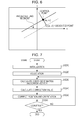
- Fig. 6 is a schematic diagram for explaining a relationship between a projected image of a line segment and a detected edge in the first embodiment of the present invention.
- Fig. 7 is a flowchart showing an example of a procedure of a position and orientation calculation in step S1040 in Fig. 3 .
- Fig. 8 is a schematic diagram for explaining an association process of a distance image and a three-dimensional shape model in step S1220 in Fig. 7 in the first embodiment of the present invention.
- Fig. 9 is a flowchart showing an example of a procedure of a position and orientation measurement process performed by a position and orientation measurement device according to a second embodiment of the present invention.
- the position and orientation of an object is estimated by using information of a grayscale image, and then the position and orientation is estimated so that a model is fitted to a feature of the grayscale image and a distance image at the same time.
- an initial value of the position and orientation is given in advance.
- an association error occurs frequently when associating a distance image (three-dimensional point group) with a three-dimensional shape model by projecting a model.
- an overlap area between a projection image of the model and an actual object image is enlarged as much as possible by estimating the position and orientation using a feature of the image, so that the number of association errors is reduced when associating the distance image.
- Fig. 1 is a block diagram showing an example of a schematic configuration of a position and orientation measurement system including a position and orientation measurement device according to a first embodiment of the present invention.
- the position and orientation measurement system includes a position and orientation measurement device 100, a gray scale image capturing unit 200, and a distance measurement unit 300.
- the position and orientation measurement device 100 includes a three-dimensional shape model storage unit 110, an approximate position and orientation input unit 120, a grayscale image input unit 130, an image feature detector 140, a distance image input unit 150, and a position and orientation calculator 160.
- the gray scale image capturing unit 200 and the distance measurement unit 300 are connected to the position and orientation measurement device 100.
- the gray scale image capturing unit 200 is a camera that captures a normal grayscale image.
- An image captured by the gray scale image capturing unit 200 may be a grayscale image or a color image.
- the image captured by the gray scale image capturing unit 200 is inputted into the position and orientation measurement device 100 via the grayscale image input unit 130.
- Internal parameters such as a focal length and a principal point of the camera and a lens distortion parameter are calibrated in advance by a method described in Z. Zhang, "A flexible new technique for camera calibration", IEEE Transactions on Pattern Analysis and Machine Intelligence, Vol.22, No.11, pages 1330-1334, 2000 .
- the distance measurement unit 300 measures a distance to a point on a surface of an object to be measured.
- a distance sensor that outputs a distance image is used as the distance measurement unit 300.
- the distance image is an image in which each pixel has information of a distance from the distance measurement unit 300.
- each pixel does not store information of a distance, but stores three-dimensional coordinates, which are calculated on the basis of the distance, in a coordinate system based on the measurement device.
- three-dimensional point group data can be obtained from the distance image.
- the distance values are converted into the three-dimensional point group by multiplying an eye vector corresponding to each pixel position by the distance values.
- an active type distance sensor is used in which an image of two-dimensional pattern light emitted to an object from a liquid crystal projector is captured by a camera and the distances are measured by triangulation.
- the distance sensor is not limited to this, but may be any distance sensor, which can output a distance image, such as a distance sensor of other active methods such as an optical cutting method and a time-of-flight method or a distance sensor of a passive method using a stereo camera.
- the same camera is used for the distance sensor and the gray scale image capturing unit 200.
- the relative positions and orientations of the distance sensor and the gray scale image capturing unit 200 are calibrated in advance. For example, an image of a calibration object whose three-dimensional shape is known is captured, and the relative positions and orientations are obtained from a position and orientation of the object based on the grayscale image and a position and orientation of the object based on the distance image.
- the distance image measured by the distance measurement unit 300 is inputted into the position and orientation measurement device 100 via the distance image input unit 150.
- the three-dimensional shape model storage unit 110 stores a three-dimensional shape model of an object whose position and orientation will be measured.
- the object is described as a three-dimensional shape model including line segments and surfaces.
- Figs. 2A to 2D are schematic diagrams for explaining a three-dimensional shape model of the first embodiment of the present invention.
- the three-dimensional shape model is defined by a set of points and a set of line segments obtained by connecting the points.
- a three-dimensional shape model of an object to be measured 10-1 is formed by 14 points P1 to P14.
- a three-dimensional shape model of an object to be measured 10-2 is formed by 16 line segments L1 to L16.
- the points P1 to P14 are represented by three-dimensional coordinate values.
- the line segments L1 to L16 are represented by IDs of points forming the line segments.
- the three-dimensional shape model holds information of surfaces. Each surface is represented by IDs of points forming the surface.
- the three-dimensional shape models shown in Figs. 2A and 2B store information of six surfaces forming a rectangular solid. The three-dimensional shape model is used when the position and orientation calculator 160 calculates a position and orientation of an object.
- the approximate position and orientation input unit 120 inputs an approximate value of position and orientation of an object with respect to the position and orientation measurement device 100.
- a three-dimensional coordinate system reference coordinate system
- the position and orientation of an object with respect to the position and orientation measurement device 100 represents the position and orientation of the object in the reference coordinate system.
- the reference coordinate system is a coordinate system in which the origin is the center of the camera which is the gray scale image capturing unit 200, the x axis is the horizontal direction of the image, the y axis is the vertical direction of the image, and the z axis is the optical axis of the camera.
- the position and orientation measurement device 100 continuously performs measurement in the time axis direction, and uses previous (previous time) measurement values as the approximate position and orientation.
- the input method of the approximate value of the position and orientation is not limited to this.
- the amount of change of the position and orientation is estimated on the basis of past measurement results of the position and orientation, and the current position and orientation may be estimated from a past position and orientation and the estimated amount of change. If an approximate position and orientation of the object is known in advance, the values of the approximate position and orientation are used as the approximated values.
- the grayscale image input unit 130 performs processing for inputting the grayscale image captured by the gray scale image capturing unit 200 into the position and orientation measurement device 100.
- the image feature detector 140 detects image features from the grayscale image inputted from the grayscale image input unit 130. In the present embodiment, edges are detected as the image features.
- the image feature detector 140 projects the line segments of the three-dimensional shape model onto the image on the basis of the approximate value of the position and orientation of the object inputted from the approximate position and orientation input unit 120 and searches for corresponding edges near the projected line segments.
- the distance image input unit 150 performs processing for inputting the distance image obtained by the distance measurement unit 300 into the position and orientation measurement device 100.
- the position and orientation calculator 160 measures the position and orientation of the object on the basis of the image features detected by the image feature detector 140, the three-dimensional point group inputted by the distance image input unit 150, and the three-dimensional shape model stored in the three-dimensional shape model storage unit 110.
- Fig. 3 is a flowchart showing an example of a procedure of a position and orientation measurement process performed by the position and orientation measurement device according to the first embodiment of the present invention.
- the approximate position and orientation input unit 120 inputs an approximate value of the position and orientation of the object with respect to the position and orientation measurement device 100 (camera) into the position and orientation measurement device 100. As described above, in the present invention, the position and orientation measured at a previous time is used as the approximate value.
- the grayscale image input unit 130 and the distance image input unit 150 obtain measurement data for calculating the position and orientation of the object. Specifically the grayscale image input unit 130 and the distance image input unit 150 obtain the grayscale image and the distance image of the object to be measured. As described above, three-dimensional coordinates of a point in the reference coordinate system is recorded in each pixel of the distance image.
- the grayscale image captured by the gray scale image capturing unit 200 is inputted into the position and orientation measurement device 100 via the grayscale image input unit 130.
- the distance image outputted from the distance measurement unit 300 is inputted into the position and orientation measurement device 100 via the distance image input unit 150.
- the image feature detector 140 and the position and orientation calculator 160 measure (calculate) the position and orientation of the object on the basis of information of the grayscale image.
- the position and orientation of the object is calculated so that the projection images of the line segments in the three-dimensional shape model fit to the edges that are the feature of the gray scale image.
- Fig. 4 is a flowchart showing an example of a procedure of the position and orientation measurement (position and orientation calculation) in step S1030 in Fig. 3 .
- the position and orientation is optimized so that the sum of squares of distances between a line segment projected on the image and a line segment based on a position and orientation which is estimated as an edge detected on the image becomes minimum.
- the position and orientation of the object is represented by a six-dimensional vector s.
- the s includes three elements that represent the position of the object to be measured and three elements that represent the orientation of the object to be measured.
- the three elements that represent the orientation are represented by, for example, Euler angles, a three dimensional vector whose direction represents a rotation axis passing through the origin and whose norm represents a rotation angle, and the like.
- step S1010 an initialization process is performed in the position and orientation measurement device 100.
- the approximate position and orientation of the object to be measured which is obtained in step S1010, is inputted as an approximate value for the position and orientation calculation.
- the image feature detector 140 detects image features and associates the image features with the three-dimensional shape model on the grayscale image inputted in step S1020.
- edges are detected as the image features.
- the edge is a point where the color density gradient is maximum.
- an edge is detected by a method disclosed in Non-Patent Document 1 described above.
- the edge detection method disclosed in Non-Patent Document 1 is a top-down type method, and a corresponding edge is searched from the model side, so that the detection and the association are performed at the same time.
- Figs. 5A and 5B are schematic diagrams for explaining the edge detection in the first embodiment of the present invention.
- images of each line segments included in the three-dimensional shape model, which are projected on the image are calculated by using the approximate value of the position and orientation of the object to be measured which is inputted in step S1110 and the calibrated internal parameters of the camera.
- the projection image of a line segment is also a line segment on the image.
- control points are set on the projected line at regular intervals on the image, and one-dimensional edge detection is performed on a line segment which passes through a control point and vertically crosses the projected line ( Fig. 5A ).
- the edge is detected as an extreme value of the color density gradient of pixel values, so that, as shown in Fig. 5B , if there is an edge near another edge, a plurality of edges may be detected.
- an edge at which the color density gradient is the largest is defined as a corresponding edge.
- the position and orientation calculator 160 calculates a coefficient matrix/error vector for calculating the position and orientation on the basis of the association of the control points on the segment lines in the three-dimensional shape model with the edges on the image.
- Fig. 6 is a schematic diagram for explaining a relationship between a projected image of a line segment and a detected edge in the first embodiment of the present invention.
- the horizontal direction and the vertical direction are respectively defined as u axis and v axis.
- a position of a control point on a line segment projected on the image on the basis of an approximate value s0 of the position and orientation is represented by (u0, v0), and an inclination of the line segment to which the control point belongs on the image is represented by an inclination ⁇ with respect to the u axis.
- the inclination ⁇ is obtained by projecting three-dimensional coordinates of both ends of the line segment on the image on the basis of the approximate value (s0) of s, and calculating the inclination of a line segment connecting the coordinates of both ends on the image.
- the normal vector of the line segment on the image is (sin ⁇ , -cos ⁇ ).
- the image coordinates of the corresponding point (edge) of the control point is defined as (u', v').
- a point (u, v) on a straight line (dashed line in Fig. 6 ) which passes through the point (u', v') and has an inclination of ⁇ is represented by the formula (1) below ( ⁇ is a constant).
- the position of the control point on the image varies depending on the position and orientation of the object to be measured.
- the image coordinates (u, v) of the control point can be approximated around (u0, v0) by a first order Taylor expansion as described by the formula (2) below.
- the observation equation of the formula (3) can be established for all associated control points.
- J of the left-hand member is the coefficient matrix to be obtained and E of the left-hand member is the error vector.
- the position and orientation calculator 160 obtains a correction value ⁇ s of the potion and orientation by a least square criterion by using a generalized inverse matrix (Jt ⁇ J)-1-Jt of the matrix J on the basis of the formula (5).
- a correction value ⁇ s of the potion and orientation by a least square criterion by using a generalized inverse matrix (Jt ⁇ J)-1-Jt of the matrix J on the basis of the formula (5).
- many association errors (outliers) occur, so that a robust estimation method described below is used.
- a value of the error vector in the right-hand member of the formula (4) is large. Therefore, a small weight is added to data whose absolute value of error is large and a large weight is added to data whose absolute value of error is small, so that influence of data whose error is large is suppressed.
- the weight is added by a Tukey function as shown by the formula (6) below.
- w ⁇ d - r ⁇ 1 - d - r c 1 2 2 0 d - r ⁇ c 1 d - r > c 1
- c1 is a constant in the formula (6).
- the function for adding a weight is not limited to the Tukey function, but any function can be used which adds a small weight to data whose error is large and adds a large weight to data whose error is small, such as, for example, a Huber function.
- the weight corresponding to each measurement data is assumed to be wi.
- a weight matrix W is defined as shown by the formula (7).
- the weight matrix W is a square matrix with all zeros except for diagonal components, and the diagonal components have weights wi.
- the formula (5) is changed to the formula (8) below by using the weight matrix W.
- WJ ⁇ s WE
- the position and orientation calculator 160 solves the formula (8) as shown by the formula (9), so that the position and orientation calculator 160 obtains the correction value ⁇ s.
- ⁇ s J T ⁇ WJ - 1 ⁇ J T ⁇ WE
- the position and orientation calculator 160 corrects the approximate value of the position and orientation by the correction value ⁇ s of the position and orientation calculated in step S1140. s ⁇ - s + ⁇ s
- the position and orientation calculator 160 determines whether the approximate value converges or not, and if the approximate value converges, the position and orientation calculator 160 ends the process of the flowchart. On the other hand, if the approximate value does not converge, the position and orientation calculator 160 returns to step S1130.
- the position and orientation calculator 160 determines that the approximate value converges when the correction value ⁇ s is substantially 0 and when the sum of squares of the error vectors hardly changes before and after the correction.
- the approximate value of the position and orientation inputted in step S1010 is updated using the information of the grayscale image.
- the overlap area between the projection image of the three-dimensional shape model on the image based on the approximate value of the position and orientation and the actual object image is enlarged, so that the number of association errors when associating the distance image with the three-dimensional shape model on the basis of the projection of the three-dimensional shape model is reduced.
- the image feature detector 140 and the position and orientation calculator 160 estimates (calculates) a position and orientation in which the three-dimensional shape model fits to both the grayscale image and the distance image by using the approximate value of the position and orientation updated in step S1030.
- the position and orientation is optimized so that a sum of the sum of squares of distances between a line segment projected on the image and a line segment based on a position and orientation which is estimated as an edge on the image and the sum of squares of distances between the three-dimensional point group and the three-dimensional shape model becomes minimum.
- Fig. 7 is a flowchart showing an example of a procedure of the position and orientation calculation in step S1040 in Fig. 3 .
- the procedure of this step is substantially the same as that of step S1030 shown in the flowchart of Fig. 4 , so that the redundant description will be omitted.
- step S1030 an initialization process is performed in the position and orientation measurement device 100.
- the approximate position and orientation of the object to be measured which is obtained in step S1030, is inputted as an approximate value for the position and orientation calculation.
- the image feature detector 140 detects image features and associates the image features with the three-dimensional shape model on the grayscale image inputted in step S1020. Similarly, the image feature detector 140 associates the distance image inputted in step S1020 with the three-dimensional shape model.
- the processing performed on the grayscale image is the same as that in step S1120, so that the description will be omitted.
- an association process of the distance image with the three-dimensional shape model will be described.
- Fig. 8 is a schematic diagram for explaining the association process of the distance image with the three-dimensional shape model in step S1220 in Fig. 7 in the first embodiment of the present invention.
- association is performed by projecting a three-dimensional model of an object (polygon model) 810 to a distance image plane 820.
- the reason why the three-dimensional model is projected onto the distance image is to determine which pixel of the distance image is associated with which polygon of the polygon model 810.
- the polygon model 810 is rendered on an image buffer having the same size as that of the distance image by using the calibrated internal parameters of the camera and the approximate value of the position and orientation.
- the image where the polygon model 810 is rendered is referred to as a polygon rendered image.
- the polygon model 810 is rendered by assigning an individual color to each polygon.
- the color of each polygon is represented by RGB color.
- polygons associated with each pixel of the distance image can be identified by the color of the image.
- the rendering of the polygons may be quickly performed on a GPU (Graphics Processing Unit) and the rendered image may be read.
- the values of each pixel of the polygon rendered image are read.
- a pixel storing a value other than black is associated with a three-dimensional coordinates stored by the pixel of the distance image and a polygon corresponding to the color on the polygon rendered image.
- the position and orientation calculator 160 calculates a coefficient matrix/error vector for calculating the position and orientation on the basis of the association of the control points on the segment lines in the three-dimensional shape model with the edges on the image and the association of the polygons with the three-dimensional points.
- the calculation of the coefficient matrix/error vector based on the association of the control points on the segment lines in the three-dimensional shape model with the edges on the image is the same as that in step S1130, so that the description will be omitted.
- the calculation method of the coefficient matrix/error vector based on the association of the pixels (three-dimensional points) of the distance image with surfaces will be described.
- the coordinate conversion from the coordinate system of the object to be measured to the reference coordinate system on the basis of the approximate value of the position and orientation is represented by the formula (10) below.
- X ⁇ Rx + t
- R is a 3x3 rotation matrix representing an orientation and t is a three-dimensional vector representing a position.
- the coefficients of the equation of a plane in the reference coordinate system are represented by the formula (11) below.
- the three-dimensional coordinates (x, y, z) of the point Q in the reference coordinate system is converted by the position and orientation s of the object to be measured, and can be approximated around three-dimensional coordinates (x0, y0, z0) at a certain position and orientation s by a first order Taylor expansion as described by the formula (12) below.
- J of the left-hand member is the coefficient matrix to be obtained and E of the left-hand member is the error vector.
- the position and orientation calculator 160 calculates the correction value ⁇ s of the position and orientation on the basis of the formula (15).
- the position and orientation calculator 160 corrects the approximate value of the position and orientation by the correction value ⁇ s of the position and orientation calculated in step S1240. s ⁇ - s + ⁇ s
- the position and orientation calculator 160 determines whether the approximate value converges or not, and if the approximate value converges, the position and orientation calculator 160 ends the process of the flowchart. On the other hand, if the approximate value does not converge, the position and orientation calculator 160 returns to step S1230.
- the position and orientation calculator 160 determines that the approximate value converges when the correction value ⁇ s is substantially 0 and when the sum of squares of the error vectors hardly changes before and after the correction.
- the position and orientation measurement device 100 of the first embodiment has the position and orientation calculator 160 that updates the approximate position and orientation of the object with respect to the position and orientation measurement device 100 so that the three-dimensional shape model fits to the image features of the gray scale image and the distance image.
- the position and orientation calculator 160 calculates a first position and orientation so that an overlap area between the object image on the image plane and the projection image of the three-dimensional shape model is the largest possible by using at least information of the grayscale image (step S1030 in Fig. 3 ). Also, the position and orientation calculator 160 calculates a second position and orientation by associating the three-dimensional shape model with the image features of the gray scale image and the distance image on the basis of the projection image of the three-dimensional shape model projected on the image plane using the first position and orientation (step S1040 in Fig. 3 ).
- the position and orientation of the object is estimated (calculated) using the grayscale image and the approximate value of the position and orientation is updated, and thereafter the distance image is associated with the three-dimensional shape model by projecting the three-dimensional shape model, so that the number of association errors is reduced.
- the position and orientation can be estimated (calculated) with a high degree of accuracy by using the grayscale image and the distance image, and the position and orientation measurement device becomes robust against a shift of the approximate value of the position and orientation.
- the first position and orientation is part of components of the position and orientation. Specifically, the first position and orientation is a position perpendicular to the optical axis of the camera of the position and orientation measurement device 100 and an orientation around the optical axis.
- three components of the position components perpendicular to the optical axis of the camera and the orientation components around the optical axis are estimated as unknown parameters. These three parameters are represented by three-dimensional vector s'.
- the image coordinates (u, v) of the control point can be approximated around (u0, v0) by a first order Taylor expansion as described by the formula (17) below.
- the process in the present modified example is effective when the shape of the projection image based on the approximate position and orientation is similar to the shape of the actual object on the image.
- the association information between the measurement data and the three-dimensional shape model is used as fixed information.
- the association information varies depending on a change of the position and orientation to be estimated. Therefore, the association process may be retried after the position and orientation is updated.
- the association process takes time, so that the association process is not retried every time the position and orientation is updated, but may be retried after the position and orientation is updated several times.
- the approximate value of the position and orientation is inputted from a past measurement result.
- the input method of the approximate value of the position and orientation is not limited to this, and the approximate value may be directly calculated on the basis of the information of the grayscale image and the distance image without performing repetitive calculations.
- the approximate position and orientation input unit 120 inputs a position and orientation of the object calculated from information of the grayscale image or the distance image by a calculation method that does not require the initial value of the position and orientation as the approximate position and orientation.
- the position and orientation may be directly calculated by associating line segments detected from the entire image with line segments in the three-dimensional shape model.
- edges are detected from the entire image by, for example, Canny's edge detector and edges adjacent to each other are labeled.
- line segment fitting is performed on edges having the same label by broken line approximation.
- the position and orientation may be calculated by Liu's method according to Y. Liu, T. S. Huang, and O. D. Faugeras, "Determination of camera location from 2-D to 3-D line and point correspondences," Proc. CVPR'88, pp. 82-88, 1988 .
- the position and orientation may be calculated on the basis of the distance image by Johnson's method according to A. Johnson and M. Hebert, "Using spin images for efficient object recognition in cluttered 3D scenes," IEEE Transactions on Pattern Analysis and Machine Intelligence, vol. 21, no. 5, pp. 433-449, 1999 .
- the position and orientation is estimated using only the grayscale image in a pre-stage process.
- the process of step S1040 is performed instead of the process of step S1030.
- a large value is used for a threshold value c1 in the formula (6) to decrease the weight in general so that the association errors of the distance image do not largely affect the calculation of the position and orientation.
- the position and orientation of the object is estimated using the grayscale image and the approximate value of the position and orientation is updated, and thereafter the distance image is associated with the three-dimensional shape model by projecting the three-dimensional shape model.
- the update method of the approximate value of the position and orientation is not limited to this.
- a position component corresponding to the depth from the camera may be estimated (calculated) using data of the distance image. If a difference between the approximate value of the position and orientation and the true value is large, it is difficult to correctly associate the distance image with the three-dimensional shape model by projecting the three-dimensional shape model.
- the distance from the camera to the surface of the object can be assumed to be substantially the same, the depth can be near the true value even if the association is somewhat incorrect.
- a position component corresponding to the depth of the object is estimated using the distance image, and thereafter, the process described in the first embodiment is performed.
- Fig. 9 is a flowchart showing an example of a procedure of a position and orientation measurement process performed by a position and orientation measurement device according to the second embodiment of the present invention.
- steps S2010, S2020, and S2040 are respectively the same as steps S1010, S1020, and S1040 in Fig. 3 of the first embodiment, so that the description thereof will be omitted.
- steps S2025 and S2030 in the process of Fig. 9 will be described.
- step S2025 for example, the position and orientation calculator 160 updates the approximate value of the position component corresponding to the depth in the position and orientation of the object on the basis of the information of the distance image.
- the position and orientation calculator 160 associates the distance image with the three-dimensional shape model by the method described in step S1220 of the first embodiment on the basis of the approximate value of the position and orientation inputted in step S2010.
- the position and orientation calculator 160 updates the position of the object on the basis of the result of the association.
- the position of the object is updated as described below.
- the position and orientation calculator 160 calculates three-dimensional coordinates of an intersection point between a light beam which is emitted from the origin of the reference coordinate system (the projection center of the camera) and passes through a pixel on the distance image which is associated with the model surface and the three-dimensional shape model surface.
- ⁇ is a parameter
- the three-dimensional coordinates stored in a pixel on the distance image is defined as xdata and the calculated three-dimensional coordinates of the intersection point is defined as xcalc.
- the position of the object t0 is updated so that an average value /zcalc of z components of xcalc corresponds to an average value /zdata of z components of xdata.
- the updated position t' is calculated by the formula (19). The reason why the z component of the position t0 is not simply updated is because the z component differently affects the position depending on an observation direction of the object.
- t ⁇ t z + z ⁇ data - z ⁇ calc t z t x t y t z
- the image feature detector 140 and the position and orientation calculator 160 measure (calculate) the position and orientation of the object on the basis of information of the grayscale image.
- the basic process is the same as that in step S1030 of the first embodiment, the approximate value of the position and orientation inputted in step S2025 is used as the inputted approximate value of the position and orientation. The description of the process after that will be omitted.
- a position component corresponding to the depth of the object is estimated using the distance image, and thereafter, the process described in the first embodiment is performed. Thereby, a shift of the approximate value of the position component corresponding to the depth is corrected, so that the number of association errors can be reduced in the process thereafter.
- the feature of the grayscale image is edges and the position and orientation is measured by fitting line segments in the three-dimensional shape model to the edges.
- the feature of the grayscale image is not limited to edges, but, for example, may be feature points that are two-dimensional features.
- the feature point is a characteristic point on an image such as a corner point.
- the feature point can be detected by Harris's detector according to C. Harris and M. Stephens, "A combined corner and edge detector" Proc. the 4th Alvey Vision Conference, pp. 147-151, 1988 .
- Harris's detector according to C. Harris and M. Stephens, "A combined corner and edge detector" Proc. the 4th Alvey Vision Conference, pp. 147-151, 1988 .
- each feature point can be associated with a point in the three-dimensional point group in the model.
- the feature points are used, first, the feature points are detected from the entire image by the Harris's detector. Next, each point in the three-dimensional point group in the model is projected on the image on the basis of the approximate value of the position and orientation, and associated with a nearest feature point on the image.
- the present invention can be implemented by performing the process described below. Specifically, in the process, software (program) that realizes functions of the embodiments described above is provided to a system or a device via a network or various storage media, and a computer (CPU or MPU) of the system or the device reads and executes the program.
- program software that realizes functions of the embodiments described above is provided to a system or a device via a network or various storage media, and a computer (CPU or MPU) of the system or the device reads and executes the program.
- the program and a computer-readable storage medium storing the program are included in the present invention.
- the post-stage estimation method of the position and orientation is not limited to this. If the object to be measured is a polyhedron which is composed of plural faces and at least three different faces are observed largely enough in the image captured by the capturing unit, it is possible to estimate the position and orientation precisely from only the distance image. And, if the object to be measured is composed of curved surfaces, and normal vectors of the object surface observed from the capturing unit are distributed enough three-dimensionally, it is possible to estimate the position and orientation precisely from only the distance image.
- the position and orientation is estimated by using only the distance image and regarding the updated approximate value as the initial value.
- the following description is a flow chart indicating an example of procedure of the position and orientation measurement device associated with the third embodiment.
- Step S3010, S3010, S3030 are the same as Step S1010, S1020, S1030 of Fig.3 in the first embodiment, so that the description will be omitted.
- the following is the description about Step S3040.
- the position and orientation calculator 160 estimates (calculates) the position and orientation so that the three -dimensional shape model fits to the distance image by using the approximate value of the position and orientation which are updated in Step S3030.
- the optimization of the position and orientation is performed so that square sum of distance between the three dimensional point group to be obtained from the distance image and the three-dimensional shape model becomes smallest.
- Step S3040 The following description is a flow chart indicating an example of procedure of the calculation of the position and orientation in Step S3040.
- the processing procedure in this step is basically the same procedure as the one in Step S1040 represented by the flow chart of Fig.7 except that the processing about the grayscale image is deleted, therefore, the redundant description will be omitted.
- an initialization process is performed in the position and orient ation measurement device 100.
- the approximate position and orientation of the object to be measured which is obtained in step S3030, is inputted as an approximate value for the position and orientation calculation.
- the image feature detector 140 associates the distance image inputted in Step S3020 with the three-dimensional shape model.
- the association process of the distance image with the three-dimensional shape model is the same as the process of Step S1220, so that the description will be omitted.
- the position and orientation calculator 160 calculates coefficient matrix/error vector for calculating the position and orientation based on the correspondences between the faces and the corresponding three dimensional points.
- the calculation method is the same as Step S1230, so that the description will be omitted.
- linear simultaneous equations for small change of each components of s are the formula (22) below a 1 ⁇ ⁇ ⁇ x ⁇ s 1 + b 1 ⁇ ⁇ ⁇ y ⁇ s 1 + c 1 ⁇ ⁇ ⁇ z ⁇ s 1 a 1 ⁇ ⁇ ⁇ x ⁇ s 2 + b 1 ⁇ ⁇ ⁇ y ⁇ s 2 + c 1 ⁇ ⁇ ⁇ z ⁇ s 2 ... a 1 ⁇ ⁇ ⁇ x ⁇ s 6 + b 1 ⁇ ⁇ ⁇ y ⁇ s 6 + c 1 ⁇ ⁇ ⁇ z ⁇ s 6 a 2 ⁇ ⁇ ⁇ x ⁇ s 1 + b 2 ⁇ ⁇ ⁇ y ⁇ s 1 + c 2 ⁇ ⁇ ⁇ z ⁇ s 1 a 2 ⁇ ⁇ ⁇ x ⁇ s 2 + b 2 ⁇ ⁇ ⁇ y ⁇ s 1
- J of the left-hand member is the coefficient matrix to be obtained and E of the right-hand member is the error vector.
- J ⁇ ⁇ ⁇ s E
- the position and orientation calculator 160 calculates the correction value ⁇ s of the position and orientation based on formula(23).
- the correction value ⁇ s is calculated by the following formula (24) by using weight matrix W.
- ⁇ ⁇ s J T ⁇ WJ - 1 ⁇ J T ⁇ WE
- the position and orientation calculator 160 by using the correction value ⁇ s of the position and orientation which are calculated in Step S3140, corrects the approximate value of the position and orientation. s ⁇ s + ⁇ ⁇ s
- the position and orientation calculator 160 determines whether the approximate value converges or not, and if the approximate value converges, the position and orientation calculator 160 ends the process of the flowchart. On the other hand, if the approximate value does not converge, the position and orientation calculator 160 returns to step S3 130.
- the position and orientation calculator 160 determines that the approximate value converges when the correction value ⁇ s is substantially 0 and when the sum of squares of the error vectors hardly changes before and after the correction.
- the position and orientation of the object is estimated by using only the distance image and regarding the updated approximate value as the initial value.
- the distance image is used for the estimation of the position and orientation with the grayscale image as the three-dimensional measurement data of the object.
- the three-dimensional measurement data used for the estimation of the position and orientation is not limited to the distance image having three-dimensional coordinates about each pixels, other measurement data representing three dimensional information of points group on the object surface may be used for the other embodiment.
- the group of three-dimensional coordinates may be used.
- the difference of this embodiment and the other embodiment is only about association of the three-dimensional shape model with the three-dimensional measurement data, so that the redundant description will be omitted.
- Step S1220 if the three-dimensional measurement data is the distance image, based on the approximate value of the position and orientation of the object, by projecting the three-dimensional shape model on the distance image, the association of pixel of the distance image with the polygon of the three-dimensional shape model is performed.
- the projection-based method cannot be used.
- the correspondence between a three-dimensional coordinate and the corresponding polygon is found by searching for the polygon which is the closest to each measurement points three-dimensionally.
- plural points(area-polygon-point) are generated on each polygon of the three-dimensional shape model more densely than the density of the measurement points, and t hree-dimensional coordinates of the area-polygon-point and the belonging Polygon ID is stored.
- searching for the each area-polygon-point corresponding to the each measurement point is performed.
- the area-polygon-point is connected to the belonging Polygon ID, therefore, the measurement point is associated with the polygon by searching.
- the estimation of the position and orientation in this invention is adapted.
- aspects of the present invention can also be realized by a computer of a system or apparatus (or devices such as a CPU or MPU) that reads out and executes a program recorded on a memory device to perform the functions of the above-described embodiment(s), and by a method, the steps of which are performed by a computer of a system or apparatus by, for example, reading out and executing a program recorded on a memory device to perform the functions of the above-described embodiment(s).
- the program is provided to the computer for example via a network or from a recording medium of various types serving as the memory device (e.g., computer-readable medium).
Abstract
Description
- The present invention relates to a position and orientation measurement device and a position and orientation measurement method for measuring a position and orientation of an object to be measured.
- In recent years, as robot technology develops, robots are beginning to perform complex tasks, such as an assembly of industrial products, which have been performed by human beings. An arm type robot is mainly used to perform such tasks, and the robot grips a part by an end effector such as a hand attached to the tip of the arm and performs an assembly. It is necessary to accurately measure relative position and orientation between the part and the robot (end effector) for the robot to appropriately grip the part. When a robotic assembly is applied to an actual assembly operation, the measurement of position and orientation of a part needs to be quick and accurate. Such a position and orientation measurement technique is required in various fields such as self-position estimation for a robot to move autonomously and creation of three-dimensional model data from actual measurement data in addition to assembly of industrial products by a robot.
- To measure position and orientation of a part in a manufacturing site of industrial products, a grayscale (or color) image obtained from a camera and a distance image obtained from a noncontact distance sensor are mainly used. Measurement of position and orientation for each object is generally performed by fitting a three-dimensional shape model of the object to measurement data (grayscale image or distance image). In T. Drummond and R. Cipolla, "Real-time visual tracking of complex structures," IEEE Transactions on Pattern Analysis and Machine Intelligence, vol.24, no.7, pp. 932-946, 2002 (hereinafter referred to as Non-Patent Document 1), a method is disclosed in which a three-dimensional shape model of an object is represented by a wireframe model that is a set of line segments and a projection image of the line segments is fitted to edges on a grayscale image, so that the position and orientation of the object is measured. In the method using the edges on the grayscale image, the position and orientation of the object is measured so that "a distance on a two-dimensional image plane" between a projection image of a portion to be an edge on the image such as a contour portion of the object and a boundary of surfaces and an edge on the image becomes minimum. Therefore, a measurement accuracy of a component of the position and orientation, which largely changes the distance on the two-dimensional image plane, is high. However, the measurement accuracy of components other than the above component is not necessarily high. Specifically, the measurement accuracy of a position component in a direction perpendicular to the optical axis of the camera and an orientation component around the optical axis is high. On the other hand, the measurement accuracy of a position component (depth) in a direction of the optical axis of the camera is low.
- In D. A. Simon, M. Hebert, and T. Kanade, "Real-time 3-D pose estimation using a high-speed range sensor," Proc. 1994 IEEE International Conference on Robotics and Automation (ICRA'94), pp. 2235-2241, 1994 (hereinafter referred to as Non-Patent Document 2), a method is disclosed in which a three-dimensional shape model (polygon model) of an object is fitted to a three-dimensional point group data on the surface of the object which is obtained from a distance image, so that the position and orientation of the object is measured. The method that uses a distance image as disclosed in Non-Patent Document 2 is a method for directly minimizing a distance "in a three-dimensional space" between the point group and the model, so that the measurement accuracy of the position and orientation is basically high. However, in an active stereo method disclosed in Satoh, Iguchi, "Distance image input by space code" Journal of Electronics, Information and Communication, vol. J68-D, no. 3, pp. 369-375, 1985, a distance of the contour portion of the object may not be able to be measured stably, so that the position and orientation at which the contour portion correctly corresponds cannot be measured depending on the shape and the observation direction of the object.
- In view of the characteristics of the method using a grayscale image and the method using a distance image described above, it can be said that there is a complementary relationship between information obtained from the grayscale image and information obtained from the distance image in the estimation of the position and orientation. Therefore, the position and orientation is measured so that the three-dimensional shape model fits to both the grayscale image and the distance image, and thereby the measurement accuracy of the position and orientation can be improved. In the methods described below which are disclosed in
Non-Patent Document 1 and Non-Patent Document 2, the sum of squares of errors between the model projection image and edges on a two-dimensional image plane and the sum of squares of errors between the model and the point group in a three-dimensional space are minimized respectively as an evaluation function. The scale of the distance on the two-dimensional image plane is different from that of the error in the three-dimensional space, so that, in a simple method that estimates the position and orientation so that the sum of the two evaluation functions becomes minimum, there is a problem that influence of one of the two evaluation functions becomes large. Conventionally, a measurement method of the position and orientation is proposed in which information of the grayscale image and information of the distance image are complementarily used by collectively evaluating errors of different scales by using a common scale. Here, as one of common scales, errors in the two-dimensional image plane and errors in the three-dimensional space are respectively represented by probabilities of occurrence (likelihoods) in probability distributions of these errors, and a highly accurate measurement of the position and orientation is performed by maximizing the product of the likelihoods. - There is a strict restriction of time in a manufacturing process of industrial products, so that a measurement of a position and orientation of a part, which is a part of the manufacturing process, needs to be performed as fast as possible. There are many other cases, in which the measurement of a position and orientation needs to be performed quickly, such as self-position estimation of a robot. The estimation of the position and orientation by fitting the three-dimensional shape model to the grayscale image and the distance image includes two steps of (1) associating the model with the image and (2) calculating the position and orientation based on a result of the association. To estimate a highly accurate position and orientation, these steps are generally repeated a plurality of times. In the two steps described above, the calculation time taken to associate the model with the image often becomes a problem.
- In the method disclosed in Non-Patent
Document 1 described above, line segments in the three-dimensional shape model are projected onto the image on the basis of an initial value of the position and orientation, and corresponding edges are searched near the projected images on the image, so that the association process of the model with the image is speeded up. On the other hand, when associating the distance image with the three-dimensional shape model, it is necessary to search for a nearest point in the three-dimensional space. - In the Non-Patent Document 2 described above, the nearest point is searched by using a kd-tree. However, in this method, a calculation in which the order is O(N log M) is required (N is the number of points in data, M is the number of points in the model), so that it takes time to use data having a large number of measurement points, such as the distance image in which each pixel becomes a measurement point.
- On the other hand, conventionally, in the same manner as the method of Non-Patent
Document 1 described above, a method in which the model is projected onto the image to speed up the association is proposed. Specifically, a calculation for projecting a geometric feature in the three-dimensional shape model onto the image is performed on the basis of an initial value of the position and orientation, and the position of the geometric feature on the image is calculated. Next, the geometric feature is associated with a pixel in the distance image on the basis of the position of the geometric feature on the image, so that a quick association is realized. - However, to associate the image with the three-dimensional shape model on the basis of the projection of the three-dimensional shape model onto the image, it is required that the projection image of the three-dimensional shape model and the image of the actual object sufficiently overlap each other. Therefore, if a shift between the initial value of the position and orientation used for projection and the actual position and orientation is large, a large number of association errors occur and the calculation of the position and orientation in a later process fails. When associating edges in the grayscale image, explicit features (edges) are used, so that the association is relatively robust against a shift of initial value.
- On the other hand, when associating the distance image, explicit features such as edges in the grayscale image are not used, so that the association is not so robust against a shift of initial value and the calculation of the position and orientation may fail. Conversely, if the shift of initial value is small and the distance image can be correctly associated with the model, it is possible to measure the position and orientation at a high degree of accuracy by using the distance image. As described above, the robust property against the shift of initial value is different between the grayscale image and the distance image. In other words, conventionally, the characteristics described above are not considered, and the robust property against the shift of initial value can be further improved by selectively using measurement data with good characteristics step-by-step.
- The present invention has been made in consideration of the above situation, and has as its object to reduce the number of association errors between the image and the three-dimensional shape model and realize a quick and robust measurement of the position and orientation of the object by using measurement data having good characteristics according to a level of shift of the initial value.
- The present invention in its first aspect provides a position and orientation measurement device as specified in
claims 1 to 7. - The present invention in its second aspect provides a position and orientation measurement method as specified in claim 8.
- Further features of the present invention will become apparent from the following description of exemplary embodiments with reference to the attached drawings.
- The accompanying drawings, which are incorporated in and constitute a part of the specification, illustrate embodiments of the invention and, together with the description, serve to explain the principles of the invention.
-
Fig. 1 is a block diagram showing an example of a schematic configuration of a position and orientation measurement system including a position and orientation measurement device according to a first embodiment of the present invention. -
Figs. 2A to 2D are schematic diagrams for explaining a three-dimensional shape model of the first embodiment of the present invention. -
Fig. 3 is a flowchart showing an example of a procedure of a position and orientation measurement process performed by the position and orientation measurement device according to the first embodiment of the present invention. -
Fig. 4 is a flowchart showing an example of a procedure of a position and orientation measurement (position and orientation calculation) in step S1030 inFig. 3 . -
Figs. 5A and 5B are schematic diagrams for explaining edge detection in the first embodiment of the present invention. -
Fig. 6 is a schematic diagram for explaining a relationship between a projected image of a line segment and a detected edge in the first embodiment of the present invention. -
Fig. 7 is a flowchart showing an example of a procedure of a position and orientation calculation in step S1040 inFig. 3 . -
Fig. 8 is a schematic diagram for explaining an association process of a distance image and a three-dimensional shape model in step S1220 inFig. 7 in the first embodiment of the present invention. -
Fig. 9 is a flowchart showing an example of a procedure of a position and orientation measurement process performed by a position and orientation measurement device according to a second embodiment of the present invention. - Embodiments of the present invention will be described in detail in accordance with the accompanying drawings.
- In a first embodiment, first, the position and orientation of an object is estimated by using information of a grayscale image, and then the position and orientation is estimated so that a model is fitted to a feature of the grayscale image and a distance image at the same time.
- In the present embodiment, an initial value of the position and orientation is given in advance. When a difference between the actual position and orientation and the initial value is large, an association error occurs frequently when associating a distance image (three-dimensional point group) with a three-dimensional shape model by projecting a model. In the first embodiment, before associating the distance image, an overlap area between a projection image of the model and an actual object image is enlarged as much as possible by estimating the position and orientation using a feature of the image, so that the number of association errors is reduced when associating the distance image.
-
Fig. 1 is a block diagram showing an example of a schematic configuration of a position and orientation measurement system including a position and orientation measurement device according to a first embodiment of the present invention. - As shown in
Fig. 1 , the position and orientation measurement system includes a position andorientation measurement device 100, a gray scaleimage capturing unit 200, and adistance measurement unit 300. - As shown in
Fig. 1 , the position andorientation measurement device 100 includes a three-dimensional shapemodel storage unit 110, an approximate position andorientation input unit 120, a grayscaleimage input unit 130, animage feature detector 140, a distanceimage input unit 150, and a position andorientation calculator 160. The gray scaleimage capturing unit 200 and thedistance measurement unit 300 are connected to the position andorientation measurement device 100. - The gray scale
image capturing unit 200 is a camera that captures a normal grayscale image. An image captured by the gray scaleimage capturing unit 200 may be a grayscale image or a color image. The image captured by the gray scaleimage capturing unit 200 is inputted into the position andorientation measurement device 100 via the grayscaleimage input unit 130. Internal parameters such as a focal length and a principal point of the camera and a lens distortion parameter are calibrated in advance by a method described in Z. Zhang, "A flexible new technique for camera calibration", IEEE Transactions on Pattern Analysis and Machine Intelligence, Vol.22, No.11, pages 1330-1334, 2000. - The
distance measurement unit 300 measures a distance to a point on a surface of an object to be measured. In the present embodiment, a distance sensor that outputs a distance image is used as thedistance measurement unit 300. The distance image is an image in which each pixel has information of a distance from thedistance measurement unit 300. In the present embodiment, each pixel does not store information of a distance, but stores three-dimensional coordinates, which are calculated on the basis of the distance, in a coordinate system based on the measurement device. In other words, three-dimensional point group data can be obtained from the distance image. The distance values are converted into the three-dimensional point group by multiplying an eye vector corresponding to each pixel position by the distance values. As the distance sensor, an active type distance sensor is used in which an image of two-dimensional pattern light emitted to an object from a liquid crystal projector is captured by a camera and the distances are measured by triangulation. The distance sensor is not limited to this, but may be any distance sensor, which can output a distance image, such as a distance sensor of other active methods such as an optical cutting method and a time-of-flight method or a distance sensor of a passive method using a stereo camera. In the present embodiment, the same camera is used for the distance sensor and the gray scaleimage capturing unit 200. - Thereby, it is assumed that a grayscale image and a distance image from the same viewpoint can be obtained. When a camera of the distance senor is different from a camera of the gray scale
image capturing unit 200, the relative positions and orientations of the distance sensor and the gray scaleimage capturing unit 200 are calibrated in advance. For example, an image of a calibration object whose three-dimensional shape is known is captured, and the relative positions and orientations are obtained from a position and orientation of the object based on the grayscale image and a position and orientation of the object based on the distance image. The distance image measured by thedistance measurement unit 300 is inputted into the position andorientation measurement device 100 via the distanceimage input unit 150. - Next, components included in the position and
orientation measurement device 100 will be described. - The three-dimensional shape
model storage unit 110 stores a three-dimensional shape model of an object whose position and orientation will be measured. In the present embodiment, the object is described as a three-dimensional shape model including line segments and surfaces. -
Figs. 2A to 2D are schematic diagrams for explaining a three-dimensional shape model of the first embodiment of the present invention. The three-dimensional shape model is defined by a set of points and a set of line segments obtained by connecting the points. As shown inFig. 2A , a three-dimensional shape model of an object to be measured 10-1 is formed by 14 points P1 to P14. As shown inFig. 2B , a three-dimensional shape model of an object to be measured 10-2 is formed by 16 line segments L1 to L16. As shown inFig. 2C , the points P1 to P14 are represented by three-dimensional coordinate values. As shown inFig. 2D , the line segments L1 to L16 are represented by IDs of points forming the line segments. Further, the three-dimensional shape model holds information of surfaces. Each surface is represented by IDs of points forming the surface. The three-dimensional shape models shown inFigs. 2A and 2B store information of six surfaces forming a rectangular solid. The three-dimensional shape model is used when the position andorientation calculator 160 calculates a position and orientation of an object. - The approximate position and
orientation input unit 120 inputs an approximate value of position and orientation of an object with respect to the position andorientation measurement device 100. In the position andorientation measurement device 100, a three-dimensional coordinate system (reference coordinate system) that is the reference of the position and orientation measurement is defined. The position and orientation of an object with respect to the position andorientation measurement device 100 represents the position and orientation of the object in the reference coordinate system. - In the present embodiment, the reference coordinate system is a coordinate system in which the origin is the center of the camera which is the gray scale
image capturing unit 200, the x axis is the horizontal direction of the image, the y axis is the vertical direction of the image, and the z axis is the optical axis of the camera. In the present embodiment, the position andorientation measurement device 100 continuously performs measurement in the time axis direction, and uses previous (previous time) measurement values as the approximate position and orientation. However, the input method of the approximate value of the position and orientation is not limited to this. For example, the amount of change of the position and orientation is estimated on the basis of past measurement results of the position and orientation, and the current position and orientation may be estimated from a past position and orientation and the estimated amount of change. If an approximate position and orientation of the object is known in advance, the values of the approximate position and orientation are used as the approximated values. - The grayscale
image input unit 130 performs processing for inputting the grayscale image captured by the gray scaleimage capturing unit 200 into the position andorientation measurement device 100. - The
image feature detector 140 detects image features from the grayscale image inputted from the grayscaleimage input unit 130. In the present embodiment, edges are detected as the image features. - Specifically, the
image feature detector 140 projects the line segments of the three-dimensional shape model onto the image on the basis of the approximate value of the position and orientation of the object inputted from the approximate position andorientation input unit 120 and searches for corresponding edges near the projected line segments. - The distance
image input unit 150 performs processing for inputting the distance image obtained by thedistance measurement unit 300 into the position andorientation measurement device 100. - The position and
orientation calculator 160 measures the position and orientation of the object on the basis of the image features detected by theimage feature detector 140, the three-dimensional point group inputted by the distanceimage input unit 150, and the three-dimensional shape model stored in the three-dimensional shapemodel storage unit 110. -
Fig. 3 is a flowchart showing an example of a procedure of a position and orientation measurement process performed by the position and orientation measurement device according to the first embodiment of the present invention. - The approximate position and
orientation input unit 120 inputs an approximate value of the position and orientation of the object with respect to the position and orientation measurement device 100 (camera) into the position andorientation measurement device 100. As described above, in the present invention, the position and orientation measured at a previous time is used as the approximate value. - The grayscale
image input unit 130 and the distanceimage input unit 150 obtain measurement data for calculating the position and orientation of the object. Specifically the grayscaleimage input unit 130 and the distanceimage input unit 150 obtain the grayscale image and the distance image of the object to be measured. As described above, three-dimensional coordinates of a point in the reference coordinate system is recorded in each pixel of the distance image. The grayscale image captured by the gray scaleimage capturing unit 200 is inputted into the position andorientation measurement device 100 via the grayscaleimage input unit 130. The distance image outputted from thedistance measurement unit 300 is inputted into the position andorientation measurement device 100 via the distanceimage input unit 150. - The
image feature detector 140 and the position andorientation calculator 160 measure (calculate) the position and orientation of the object on the basis of information of the grayscale image. In step S1030, the position and orientation of the object is calculated so that the projection images of the line segments in the three-dimensional shape model fit to the edges that are the feature of the gray scale image. -
Fig. 4 is a flowchart showing an example of a procedure of the position and orientation measurement (position and orientation calculation) in step S1030 inFig. 3 . Here, the position and orientation is optimized so that the sum of squares of distances between a line segment projected on the image and a line segment based on a position and orientation which is estimated as an edge detected on the image becomes minimum. In the description below, the position and orientation of the object is represented by a six-dimensional vector s. The s includes three elements that represent the position of the object to be measured and three elements that represent the orientation of the object to be measured. The three elements that represent the orientation are represented by, for example, Euler angles, a three dimensional vector whose direction represents a rotation axis passing through the origin and whose norm represents a rotation angle, and the like. - Hereinafter, the procedure of the position and orientation calculation in step S1030 in
Fig. 3 will be described. - First, an initialization process is performed in the position and
orientation measurement device 100. Here, the approximate position and orientation of the object to be measured, which is obtained in step S1010, is inputted as an approximate value for the position and orientation calculation. - Next, the
image feature detector 140 detects image features and associates the image features with the three-dimensional shape model on the grayscale image inputted in step S1020. In the present embodiment, edges are detected as the image features. The edge is a point where the color density gradient is maximum. In the present embodiment, an edge is detected by a method disclosed inNon-Patent Document 1 described above. The edge detection method disclosed inNon-Patent Document 1 is a top-down type method, and a corresponding edge is searched from the model side, so that the detection and the association are performed at the same time. -
Figs. 5A and 5B are schematic diagrams for explaining the edge detection in the first embodiment of the present invention. First, here, images of each line segments included in the three-dimensional shape model, which are projected on the image, are calculated by using the approximate value of the position and orientation of the object to be measured which is inputted in step S1110 and the calibrated internal parameters of the camera. The projection image of a line segment is also a line segment on the image. Next, control points are set on the projected line at regular intervals on the image, and one-dimensional edge detection is performed on a line segment which passes through a control point and vertically crosses the projected line (Fig. 5A ). The edge is detected as an extreme value of the color density gradient of pixel values, so that, as shown inFig. 5B , if there is an edge near another edge, a plurality of edges may be detected. - In the present embodiment, among the detected edges, an edge at which the color density gradient is the largest is defined as a corresponding edge.
- Next, for example, the position and
orientation calculator 160 calculates a coefficient matrix/error vector for calculating the position and orientation on the basis of the association of the control points on the segment lines in the three-dimensional shape model with the edges on the image. -
Fig. 6 is a schematic diagram for explaining a relationship between a projected image of a line segment and a detected edge in the first embodiment of the present invention. - In
Fig. 6 , the horizontal direction and the vertical direction are respectively defined as u axis and v axis. A position of a control point on a line segment projected on the image on the basis of an approximate value s0 of the position and orientation is represented by (u0, v0), and an inclination of the line segment to which the control point belongs on the image is represented by an inclination θ with respect to the u axis. The inclination θ is obtained by projecting three-dimensional coordinates of both ends of the line segment on the image on the basis of the approximate value (s0) of s, and calculating the inclination of a line segment connecting the coordinates of both ends on the image. The normal vector of the line segment on the image is (sinθ, -cosθ). The image coordinates of the corresponding point (edge) of the control point is defined as (u', v'). Here, a point (u, v) on a straight line (dashed line inFig. 6 ) which passes through the point (u', v') and has an inclination of θ is represented by the formula (1) below (θ is a constant).
Here, d = u'sinθ - v'cosθ (constant) - The position of the control point on the image varies depending on the position and orientation of the object to be measured. The image coordinates (u, v) of the control point can be approximated around (u0, v0) by a first order Taylor expansion as described by the formula (2) below. Here, Δsi (i = 1, 2, ···, 6) indicates a minor change of each component of s.

- If it is assumed that the position of the control point on the image obtained from a correct s is located on a straight line represented by the formula (1), the formula (3) below, which is an observation equation, can be obtained by substituting the formula (2) into the formula (1).

Here, r = u0sinθ - v0cosθ (constant) - The observation equation of the formula (3) can be established for all associated control points. The formula (3) is an equation for a minor change Δsi (i = 1, 2, ···, 6) of each component of s, and linear simultaneous equations related to Δsi shown by the formula (4) below can be established.

- The linear simultaneous equations are represented as the formula (5) below.

- In the formula (5), J of the left-hand member is the coefficient matrix to be obtained and E of the left-hand member is the error vector.
- Next, for example, the position and
orientation calculator 160 obtains a correction value Δs of the potion and orientation by a least square criterion by using a generalized inverse matrix (Jt·J)-1-Jt of the matrix J on the basis of the formula (5). However, when associating the edge, many association errors (outliers) occur, so that a robust estimation method described below is used. Generally, at an outlier edge, a value of the error vector in the right-hand member of the formula (4) is large. Therefore, a small weight is added to data whose absolute value of error is large and a large weight is added to data whose absolute value of error is small, so that influence of data whose error is large is suppressed. For example, the weight is added by a Tukey function as shown by the formula (6) below.
- Here, c1 is a constant in the formula (6). The function for adding a weight is not limited to the Tukey function, but any function can be used which adds a small weight to data whose error is large and adds a large weight to data whose error is small, such as, for example, a Huber function. The weight corresponding to each measurement data is assumed to be wi. Here, a weight matrix W is defined as shown by the formula (7).

- The weight matrix W is a square matrix with all zeros except for diagonal components, and the diagonal components have weights wi. The formula (5) is changed to the formula (8) below by using the weight matrix W.

- Then, for example, the position and
orientation calculator 160 solves the formula (8) as shown by the formula (9), so that the position andorientation calculator 160 obtains the correction value Δs.
- Next, for example, the position and
orientation calculator 160 corrects the approximate value of the position and orientation by the correction value Δs of the position and orientation calculated in step S1140.
- Next, for example, the position and
orientation calculator 160 determines whether the approximate value converges or not, and if the approximate value converges, the position andorientation calculator 160 ends the process of the flowchart. On the other hand, if the approximate value does not converge, the position andorientation calculator 160 returns to step S1130. The position andorientation calculator 160 determines that the approximate value converges when the correction value Δs is substantially 0 and when the sum of squares of the error vectors hardly changes before and after the correction. - By the above processing, the approximate value of the position and orientation inputted in step S1010 is updated using the information of the grayscale image. As a result, the overlap area between the projection image of the three-dimensional shape model on the image based on the approximate value of the position and orientation and the actual object image is enlarged, so that the number of association errors when associating the distance image with the three-dimensional shape model on the basis of the projection of the three-dimensional shape model is reduced.
- Next, a calculation process of the position and orientation using the grayscale image and the distance image will be described. In this step, the
image feature detector 140 and the position andorientation calculator 160 estimates (calculates) a position and orientation in which the three-dimensional shape model fits to both the grayscale image and the distance image by using the approximate value of the position and orientation updated in step S1030. Here, the position and orientation is optimized so that a sum of the sum of squares of distances between a line segment projected on the image and a line segment based on a position and orientation which is estimated as an edge on the image and the sum of squares of distances between the three-dimensional point group and the three-dimensional shape model becomes minimum. -
Fig. 7 is a flowchart showing an example of a procedure of the position and orientation calculation in step S1040 inFig. 3 . The procedure of this step is substantially the same as that of step S1030 shown in the flowchart ofFig. 4 , so that the redundant description will be omitted. - First, an initialization process is performed in the position and
orientation measurement device 100. Here, the approximate position and orientation of the object to be measured, which is obtained in step S1030, is inputted as an approximate value for the position and orientation calculation. - Next, the
image feature detector 140 detects image features and associates the image features with the three-dimensional shape model on the grayscale image inputted in step S1020. Similarly, theimage feature detector 140 associates the distance image inputted in step S1020 with the three-dimensional shape model. The processing performed on the grayscale image is the same as that in step S1120, so that the description will be omitted. Hereinafter, an association process of the distance image with the three-dimensional shape model will be described. -
Fig. 8 is a schematic diagram for explaining the association process of the distance image with the three-dimensional shape model in step S1220 inFig. 7 in the first embodiment of the present invention. - In this step, in the same manner as in a method disclosed in Oishi, Nakazawa, Ikeuchi, "Quick simultaneous position matching of multiple distance images using index image" vol. J89-D, no. 3, pp. 513-521, 2006, association is performed by projecting a three-dimensional model of an object (polygon model) 810 to a
distance image plane 820. Here, the reason why the three-dimensional model is projected onto the distance image is to determine which pixel of the distance image is associated with which polygon of thepolygon model 810. Here, thepolygon model 810 is rendered on an image buffer having the same size as that of the distance image by using the calibrated internal parameters of the camera and the approximate value of the position and orientation. Hereinafter, the image where thepolygon model 810 is rendered is referred to as a polygon rendered image. - The
polygon model 810 is rendered by assigning an individual color to each polygon. The color of each polygon is represented by RGB color. To distinguish from the background, the polygons are rendered by using colors other than black (R=0, G=0, and B=0). Thereby, polygons associated with each pixel of the distance image can be identified by the color of the image. The rendering of the polygons may be quickly performed on a GPU (Graphics Processing Unit) and the rendered image may be read. After thepolygon model 810 is rendered, the values of each pixel of the polygon rendered image are read. A pixel storing a value other than black is associated with a three-dimensional coordinates stored by the pixel of the distance image and a polygon corresponding to the color on the polygon rendered image. - Next, for example, the position and
orientation calculator 160 calculates a coefficient matrix/error vector for calculating the position and orientation on the basis of the association of the control points on the segment lines in the three-dimensional shape model with the edges on the image and the association of the polygons with the three-dimensional points. The calculation of the coefficient matrix/error vector based on the association of the control points on the segment lines in the three-dimensional shape model with the edges on the image is the same as that in step S1130, so that the description will be omitted. Hereinafter, the calculation method of the coefficient matrix/error vector based on the association of the pixels (three-dimensional points) of the distance image with surfaces will be described. - An equation of a plane in three-dimensional space is generally represented by ax + by + cz = e(a2+b2+c2=1). Here, an equation of a plane in a coordinate system of an object to be measured in a certain surface of the three-dimensional shape model is assumed to be ax + by + cz = e. The equation of a plane can be converted into an equation of a plane a'x + b'y + c'z = e' in the reference coordinate system on the basis of the approximate value of the position and orientation. The coordinate conversion from the coordinate system of the object to be measured to the reference coordinate system on the basis of the approximate value of the position and orientation is represented by the formula (10) below.

- Here, in the formula (10), R is a 3x3 rotation matrix representing an orientation and t is a three-dimensional vector representing a position. At this time, the coefficients of the equation of a plane in the reference coordinate system are represented by the formula (11) below.

- The coordinate conversion of a plane is described in detail in, for example, Kanaya, "Shape CAD and geometry mathematics" (Kyoritsu Shuppan). It is assumed that a point P whose measurement value of the three-dimensional coordinates in the reference coordinate system is (x', y', z') is associated with a surface F in the three-dimensional shape model. A foot of a perpendicular drawn from the point P to the surface F is defined as Q. The three-dimensional coordinates (x, y, z) of the point Q in the reference coordinate system is converted by the position and orientation s of the object to be measured, and can be approximated around three-dimensional coordinates (x0, y0, z0) at a certain position and orientation s by a first order Taylor expansion as described by the formula (12) below.

- If it is assumed that (x, y, z) converted by a correct s is located on a plane (a'x + b'y + c'z = e', e' = a'x' + b'y' + c'z') which has the same normal vector as that of the surface F and passes through the point P, the formula (13) below can be obtained by substituting the formula (12) into the equation of the plane.

Here, q = a'x0 + b'y0 + c'z0 (constant) - The observation equation of the formula (13) can be established for all associated point group data.
- The observation equations of the formula (3) and the formula (13) are equations for a minor change Δsi (i = 1, 2, ···, 6) of each component of s, and the linear simultaneous equations related to Δsi shown by the formula (13) can be established as shown by the formula (14) below.

- The linear simultaneous equations shown by the formula (14) are represented as the formula (15) below.

- In the formula (15), J of the left-hand member is the coefficient matrix to be obtained and E of the left-hand member is the error vector.
- Next, for example, the position and
orientation calculator 160 calculates the correction value Δs of the position and orientation on the basis of the formula (15). However, it is inevitable that outliers such as association errors are mixed into data associated with the edges and data associated with the distance data. Therefore, by the robust estimation method as described in step S1140, the correction value Δs is calculated by the formula (16) using the weight matrix W.
- Next, for example, the position and
orientation calculator 160 corrects the approximate value of the position and orientation by the correction value Δs of the position and orientation calculated in step S1240.
- Next, for example, the position and
orientation calculator 160 determines whether the approximate value converges or not, and if the approximate value converges, the position andorientation calculator 160 ends the process of the flowchart. On the other hand, if the approximate value does not converge, the position andorientation calculator 160 returns to step S1230. The position andorientation calculator 160 determines that the approximate value converges when the correction value Δs is substantially 0 and when the sum of squares of the error vectors hardly changes before and after the correction. - As described above, the position and
orientation measurement device 100 of the first embodiment has the position andorientation calculator 160 that updates the approximate position and orientation of the object with respect to the position andorientation measurement device 100 so that the three-dimensional shape model fits to the image features of the gray scale image and the distance image. - The position and
orientation calculator 160 calculates a first position and orientation so that an overlap area between the object image on the image plane and the projection image of the three-dimensional shape model is the largest possible by using at least information of the grayscale image (step S1030 inFig. 3 ). Also, the position andorientation calculator 160 calculates a second position and orientation by associating the three-dimensional shape model with the image features of the gray scale image and the distance image on the basis of the projection image of the three-dimensional shape model projected on the image plane using the first position and orientation (step S1040 inFig. 3 ). - In this way, in the first embodiment, the position and orientation of the object is estimated (calculated) using the grayscale image and the approximate value of the position and orientation is updated, and thereafter the distance image is associated with the three-dimensional shape model by projecting the three-dimensional shape model, so that the number of association errors is reduced. As a result, the position and orientation can be estimated (calculated) with a high degree of accuracy by using the grayscale image and the distance image, and the position and orientation measurement device becomes robust against a shift of the approximate value of the position and orientation.
- In the first embodiment described above, in the estimation of the position and orientation using only the grayscale image, which is a pre-stage process, all of the six freedoms of the position and orientation are estimated. However, in this process, not all the freedoms are required to be estimated, and only the components, by which the position and orientation can be estimated with a high degree of accuracy using the grayscale image, may be estimated. When the background and the structure of the object are complicated, it is inevitable that the edges on the grayscale image are mis-associated with the model. When the components to be estimated are limited, over-fitting to the measurement data is mitigated, so that robust property against association error can be expected to be improved. In the present modified example, the first position and orientation is part of components of the position and orientation. Specifically, the first position and orientation is a position perpendicular to the optical axis of the camera of the position and
orientation measurement device 100 and an orientation around the optical axis. - In the present modified example, three components of the position components perpendicular to the optical axis of the camera and the orientation components around the optical axis are estimated as unknown parameters. These three parameters are represented by three-dimensional vector s'. The image coordinates (u, v) of the control point can be approximated around (u0, v0) by a first order Taylor expansion as described by the formula (17) below. Here, Δs'i (i = 1, 2, and 3) indicates a minor change of each component of s'.

- The formula (18) below, which is an observation equation, can be obtained by substituting the formula (17) into the formula (1).

- The correction value Δs'i (i = 1, 2, and 3) is calculated by the same process as that in the first embodiment by using the formula (18) established for all the associated control points as simultaneous equations.
- The process in the present modified example is effective when the shape of the projection image based on the approximate position and orientation is similar to the shape of the actual object on the image.
- In the first embodiment described above, in the calculation process of the position and orientation in steps S1030 and S1040, the association information between the measurement data and the three-dimensional shape model is used as fixed information. However, in practice, the association information varies depending on a change of the position and orientation to be estimated. Therefore, the association process may be retried after the position and orientation is updated. However, the association process takes time, so that the association process is not retried every time the position and orientation is updated, but may be retried after the position and orientation is updated several times.
- In the first embodiment described above, the approximate value of the position and orientation is inputted from a past measurement result. However, the input method of the approximate value of the position and orientation is not limited to this, and the approximate value may be directly calculated on the basis of the information of the grayscale image and the distance image without performing repetitive calculations. In this case, the approximate position and
orientation input unit 120 inputs a position and orientation of the object calculated from information of the grayscale image or the distance image by a calculation method that does not require the initial value of the position and orientation as the approximate position and orientation. For example, the position and orientation may be directly calculated by associating line segments detected from the entire image with line segments in the three-dimensional shape model. Specifically, first, edges are detected from the entire image by, for example, Canny's edge detector and edges adjacent to each other are labeled. Next, line segment fitting is performed on edges having the same label by broken line approximation. On the basis of the association of the line segments on the image with the line segments in the three-dimensional shape model obtained in this way, the position and orientation may be calculated by Liu's method according to Y. Liu, T. S. Huang, and O. D. Faugeras, "Determination of camera location from 2-D to 3-D line and point correspondences," Proc. CVPR'88, pp. 82-88, 1988. Also, for example, the position and orientation may be calculated on the basis of the distance image by Johnson's method according to A. Johnson and M. Hebert, "Using spin images for efficient object recognition in cluttered 3D scenes," IEEE Transactions on Pattern Analysis and Machine Intelligence, vol. 21, no. 5, pp. 433-449, 1999. - In the first embodiment described above, the position and orientation is estimated using only the grayscale image in a pre-stage process. However, not only the information of the grayscale image, but also the information of the distance image may be used within the extent that the association errors do not exert a bad influence. Specifically, the process of step S1040 is performed instead of the process of step S1030. At this time, a large value is used for a threshold value c1 in the formula (6) to decrease the weight in general so that the association errors of the distance image do not largely affect the calculation of the position and orientation. Second Embodiment (obtain depth before 2D)
- In the first embodiment described above, first, the position and orientation of the object is estimated using the grayscale image and the approximate value of the position and orientation is updated, and thereafter the distance image is associated with the three-dimensional shape model by projecting the three-dimensional shape model. However, the update method of the approximate value of the position and orientation is not limited to this. For example, in the position and orientation, a position component corresponding to the depth from the camera may be estimated (calculated) using data of the distance image.
If a difference between the approximate value of the position and orientation and the true value is large, it is difficult to correctly associate the distance image with the three-dimensional shape model by projecting the three-dimensional shape model. However, when the distance from the camera to the surface of the object can be assumed to be substantially the same, the depth can be near the true value even if the association is somewhat incorrect. - Therefore, in the present embodiment, first, a position component corresponding to the depth of the object is estimated using the distance image, and thereafter, the process described in the first embodiment is performed. Thereby, even when an approximate value of the position component corresponding to the depth is largely different from the true value, the position and orientation is robustly measured (calculated).
-
Fig. 9 is a flowchart showing an example of a procedure of a position and orientation measurement process performed by a position and orientation measurement device according to the second embodiment of the present invention. - Among the steps, steps S2010, S2020, and S2040 are respectively the same as steps S1010, S1020, and S1040 in
Fig. 3 of the first embodiment, so that the description thereof will be omitted. Hereinafter, steps S2025 and S2030 in the process ofFig. 9 will be described. - In step S2025, for example, the position and
orientation calculator 160 updates the approximate value of the position component corresponding to the depth in the position and orientation of the object on the basis of the information of the distance image. - Specifically, first, the position and
orientation calculator 160 associates the distance image with the three-dimensional shape model by the method described in step S1220 of the first embodiment on the basis of the approximate value of the position and orientation inputted in step S2010. Next, for example, the position andorientation calculator 160 updates the position of the object on the basis of the result of the association. The position of the object is updated as described below. Here, the three-dimensional vector representing the approximate value of the position of the object in the reference coordinate system is defined as t0 = [tx ty tz]t. Next, for example, the position andorientation calculator 160 calculates three-dimensional coordinates of an intersection point between a light beam which is emitted from the origin of the reference coordinate system (the projection center of the camera) and passes through a pixel on the distance image which is associated with the model surface and the three-dimensional shape model surface. When the direction vector of the light beam is d = [dx dy dz]t, three-dimensional coordinates x of a point on the light beam is represented by x = αd (α is a parameter). When it is assumed that this point is located on the model surface a'x + b'y + c'z = e', α is obtained and x is calculated, so that the three-dimensional coordinates of the intersection point are calculated. The three-dimensional coordinates stored in a pixel on the distance image is defined as xdata and the calculated three-dimensional coordinates of the intersection point is defined as xcalc. The position of the object t0 is updated so that an average value /zcalc of z components of xcalc corresponds to an average value /zdata of z components of xdata. The updated position t' is calculated by the formula (19). The reason why the z component of the position t0 is not simply updated is because the z component differently affects the position depending on an observation direction of the object.
- The
image feature detector 140 and the position andorientation calculator 160 measure (calculate) the position and orientation of the object on the basis of information of the grayscale image. Although the basic process is the same as that in step S1030 of the first embodiment, the approximate value of the position and orientation inputted in step S2025 is used as the inputted approximate value of the position and orientation. The description of the process after that will be omitted. - In this way, in the second embodiment, a position component corresponding to the depth of the object is estimated using the distance image, and thereafter, the process described in the first embodiment is performed. Thereby, a shift of the approximate value of the position component corresponding to the depth is corrected, so that the number of association errors can be reduced in the process thereafter.
- In the embodiments and the modified examples of the present invention, the feature of the grayscale image is edges and the position and orientation is measured by fitting line segments in the three-dimensional shape model to the edges. However, the feature of the grayscale image is not limited to edges, but, for example, may be feature points that are two-dimensional features. The feature point is a characteristic point on an image such as a corner point. For example, the feature point can be detected by Harris's detector according to C. Harris and M. Stephens, "A combined corner and edge detector" Proc. the 4th Alvey Vision Conference, pp. 147-151, 1988. When the three-dimensional shape model is represented by a three-dimensional point group, each feature point can be associated with a point in the three-dimensional point group in the model. When the feature points are used, first, the feature points are detected from the entire image by the Harris's detector. Next, each point in the three-dimensional point group in the model is projected on the image on the basis of the approximate value of the position and orientation, and associated with a nearest feature point on the image.
- The present invention can be implemented by performing the process described below. Specifically, in the process, software (program) that realizes functions of the embodiments described above is provided to a system or a device via a network or various storage media, and a computer (CPU or MPU) of the system or the device reads and executes the program.
- The program and a computer-readable storage medium storing the program are included in the present invention.
- In the other embodiment described above, in the post-stage estimation of the position and orientation, the both information of the grayscale image and the distance image is used. However, the post-stage estimation method of the position and orientation is not limited to this. If the object to be measured is a polyhedron which is composed of plural faces and at least three different faces are observed largely enough in the image captured by the capturing unit, it is possible to estimate the position and orientation precisely from only the distance image. And, if the object to be measured is composed of curved surfaces, and normal vectors of the object surface observed from the capturing unit are distributed enough three-dimensionally, it is possible to estimate the position and orientation precisely from only the distance image.
- Then, in the present embodiment, at first, as it is described in the first embodiment, after updating the approximate value of the position and orientation by using the grayscale image, the position and orientation is estimated by using only the distance image and regarding the updated approximate value as the initial value.
- The following description is a flow chart indicating an example of procedure of the position and orientation measurement device associated with the third embodiment.
- In each steps, Step S3010, S3010, S3030 are the same as Step S1010, S1020, S1030 of
Fig.3 in the first embodiment, so that the description will be omitted. The following is the description about Step S3040. - In this step, the position and
orientation calculator 160 estimates (calculates) the position and orientation so that the three -dimensional shape model fits to the distance image by using the approximate value of the position and orientation which are updated in Step S3030. Here, the optimization of the position and orientation is performed so that square sum of distance between the three dimensional point group to be obtained from the distance image and the three-dimensional shape model becomes smallest. - The following description is a flow chart indicating an example of procedure of the calculation of the position and orientation in Step S3040.
- The processing procedure in this step is basically the same procedure as the one in Step S1040 represented by the flow chart of
Fig.7 except that the processing about the grayscale image is deleted, therefore, the redundant description will be omitted. - First, an initialization process is performed in the position and
orient ation measurement device 100. Here, the approximate position and orientation of the object to be measured, which is obtained in step S3030, is inputted as an approximate value for the position and orientation calculation. - Next, the
image feature detector 140 associates the distance image inputted in Step S3020 with the three-dimensional shape model. The association process of the distance image with the three-dimensional shape model is the same as the process of Step S1220, so that the description will be omitted. - Next , for example, the position and
orientation calculator 160 calculates coefficient matrix/error vector for calculating the position and orientation based on the correspondences between the faces and the corresponding three dimensional points. The calculation method is the same as Step S1230, so that the description will be omitted. In this step, information of only the distance image is used, therefore, linear simultaneous equations for small change of each components of s are the formula (22) below
- The linear simultaneous equations represented by this formula(22) are represented as the formula(23) below.
- In the formula(23), J of the left-hand member is the coefficient matrix to be obtained and E of the right-hand member is the error vector.

- Next , for example, the position and
orientation calculator 160 calculates the correction value Δs of the position and orientation based on formula(23). - It is inevitable that the correspondence data includes outliers which have large errors caused by wrong correspondence, therefore, applying the robust estimation method as described in step S1140, the correction value Δ s is calculated by the following formula (24) by using weight matrix W.

- Next , for example, the position and
orientation calculator 160 , by using the correction value Δs of the position and orientation which are calculated in Step S3140, corrects the approximate value of the position and orientation.
- Next, for example, the position and
orientation calculator 160 determines whether the approximate value converges or not, and if the approximate value converges, the position andorientation calculator 160 ends the process of the flowchart. On the other hand, if the approximate value does not converge, the position andorientation calculator 160 returns to step S3130. The position andorientation calculator 160 determines that the approximate value converges when the correction value Δs is substantially 0 and when the sum of squares of the error vectors hardly changes before and after the correction.
as it is described in the aforementioned embodiment, in the third embodiment, at first, after estimating the approximate value of the position and orientation of the object by using the grayscale image, the position and orientation of the object is estimated by using only the distance image and regarding the updated approximate value as the initial value. By this way, If estimation is performed precisely from only the distance image, in post-processing, the processing about the grayscale image is needless, therefore, it is possible to calculate the position and orientation rapidly. - In the other embodiment described above, the distance image is used for the estimation of the position and orientation with the grayscale image as the three-dimensional measurement data of the object. However, the three-dimensional measurement data used for the estimation of the position and orientation is not limited to the distance image having three-dimensional coordinates about each pixels, other measurement data representing three dimensional information of points group on the object surface may be used for the other embodiment. For example, the group of three-dimensional coordinates may be used. On the other hand, the difference of this embodiment and the other embodiment is only about association of the three-dimensional shape model with the three-dimensional measurement data, so that the redundant description will be omitted.
- As described in the explanation of Step S1220, if the three-dimensional measurement data is the distance image, based on the approximate value of the position and orientation of the object, by projecting the three-dimensional shape model on the distance image, the association of pixel of the distance image with the polygon of the three-dimensional shape model is performed.
- If the three-dimensional measurement data is the group of three-dimensional coordinates, the projection-based method cannot be used. In this case, the correspondence between a three-dimensional coordinate and the corresponding polygon is found by searching for the polygon which is the closest to each measurement points three-dimensionally. The detailed explanation is following.
- At first, plural points(area-polygon-point) are generated on each polygon of the three-dimensional shape model more densely than the density of the measurement points, and three-dimensional coordinates of the area-polygon-point and the belonging Polygon ID is stored. In case of the association, by using k- d tree, searching for the each area-polygon-point corresponding to the each measurement point is performed. The area-polygon-point is connected to the belonging Polygon ID, therefore, the measurement point is associated with the polygon by searching.
- As it is described in the aforementioned embodiment, if the three-dimensional measurement data of the object is not the distance image having three-dimensional coordinates about each pixel, the estimation of the position and orientation in this invention is adapted.
- Aspects of the present invention can also be realized by a computer of a system or apparatus (or devices such as a CPU or MPU) that reads out and executes a program recorded on a memory device to perform the functions of the above-described embodiment(s), and by a method, the steps of which are performed by a computer of a system or apparatus by, for example, reading out and executing a program recorded on a memory device to perform the functions of the above-described embodiment(s). For this purpose, the program is provided to the computer for example via a network or from a recording medium of various types serving as the memory device (e.g., computer-readable medium).
- While the present invention has been described with reference to exemplary embodiments, it is to be understood that the invention is not limited to the disclosed exemplary embodiments. The scope of the following claims is to be accorded the broadest interpretation so as to encompass all such modifications and equivalent structures and functions.
Claims (8)
- A position and orientation measurement device that measures a position and orientation of an object to be measured, the device comprising:storage means (110) configured to store a three-dimensional shape model of the object;grayscale image input means (130) configured to input a grayscale image of the object;distance image input means (150)configured to input a distance image of the object;approximate position and orientation input means (120) configured to input an approximate position and orientation of the object with respect to the position and orientation measurement device; andposition and orientation calculation means (160) configured to update the approximate position and orientation so that the three-dimensional shape model fits to image features of the grayscale image and the distance image,wherein the position and orientation calculation means (160) is configured to calculate a first position and orientation so that an object image on an image plane and a projection image of the three-dimensional shape model on the image plane overlap each other by using at least information of the grayscale image, to associate the three-dimensional shape model with the image features of the grayscale image and the distance image on the basis of the projection image of the three-dimensional shape model projected onto the image plane by using the first position and orientation, and to calculate a second position and orientation on the basis of a result of the association, and to update the approximate position and orientation with the calculated second position and orientation.
- The position and orientation measurement device according to Claim 1, wherein the first position and orientation calculated by the position and orientation calculation means is a component of the position and orientation of the object.
- The position and orientation measurement device according to Claim 2, wherein the first position and orientation is a position in a direction perpendicular to an optical axis of a camera of the position and orientation measurement device and an orientation around the optical axis.
- The position and orientation measurement device according to any preceding claim, wherein the approximate position and orientation input means is configured to input a position and orientation of the object calculated from information of the grayscale image or the distance image by a calculation method that does not require an initial value of the position and orientation asan approximate position and orientation.
- The position and orientation measurement device according to any preceding claim, wherein the position and orientation calculation means is configured to calculate a position corresponding to a depth from the position and orientation measurement device to the object by using information of the distance image before calculating the first position and orientation, and to calculate the first position and orientation using the calculated position corresponding to the depth.
- The position and orientation measurement device according to any preceding claim, wherein the image features comprise edges.
- The position and orientation measurement device according to any preceding claim, wherein the image features comprise feature points.
- A position and orientation measurement method by a position and orientation measurement device that measures position and orientation of an object to be measured, the method comprising:a storage step for storing a three-dimensional shape model of the object;a grayscale image input step for inputting a grayscale image of the object;a distance image input step for inputting a distance image of the object;an approximate position and orientation input step for inputting an approximate position and orientation of the object with respect to the position and orientation measurement device; anda position and orientation calculation step for updating the approximate position and orientation so that the three-dimensional shape model fits to image features of the grayscale image and the distance image,wherein the position and orientation calculation step comprises calculating a first position and orientation so that an object image on an image plane and a projection image of the three-dimensional shape model overlap each other by using at least information of the grayscale image, associating the three-dimensional shape model with the image features of the grayscale image and the distance image on the basis of the projection image of the three-dimensional shape model projected onto the image plane by using the first position and orientation, and calculating a second position and orientation on the basis of a result of the association.
Applications Claiming Priority (1)
| Application Number | Priority Date | Filing Date | Title |
|---|---|---|---|
| JP2010278270 | 2010-12-14 |
Publications (3)
| Publication Number | Publication Date |
|---|---|
| EP2466543A2 true EP2466543A2 (en) | 2012-06-20 |
| EP2466543A3 EP2466543A3 (en) | 2017-04-26 |
| EP2466543B1 EP2466543B1 (en) | 2018-07-04 |
Family
ID=45440183
Family Applications (1)
| Application Number | Title | Priority Date | Filing Date |
|---|---|---|---|
| EP11193591.2A Not-in-force EP2466543B1 (en) | 2010-12-14 | 2011-12-14 | Position and orientation measurement device and position and orientation measurement method |
Country Status (3)
| Country | Link |
|---|---|
| US (1) | US9519971B2 (en) |
| EP (1) | EP2466543B1 (en) |
| JP (1) | JP5839971B2 (en) |
Cited By (1)
| Publication number | Priority date | Publication date | Assignee | Title |
|---|---|---|---|---|
| US20120148100A1 (en) * | 2010-12-14 | 2012-06-14 | Canon Kabushiki Kaisha | Position and orientation measurement device and position and orientation measurement method |
Families Citing this family (30)
| Publication number | Priority date | Publication date | Assignee | Title |
|---|---|---|---|---|
| JP5496008B2 (en) * | 2010-08-06 | 2014-05-21 | キヤノン株式会社 | Position / orientation measuring apparatus, position / orientation measuring method, and program |
| JP5671281B2 (en) * | 2010-08-20 | 2015-02-18 | キヤノン株式会社 | Position / orientation measuring apparatus, control method and program for position / orientation measuring apparatus |
| JP5839929B2 (en) * | 2010-11-19 | 2016-01-06 | キヤノン株式会社 | Information processing apparatus, information processing system, information processing method, and program |
| US20140081459A1 (en) * | 2012-09-20 | 2014-03-20 | Marc Dubois | Depth mapping vision system with 2d optical pattern for robotic applications |
| US9772173B2 (en) * | 2013-06-27 | 2017-09-26 | Faro Technologies, Inc. | Method for measuring 3D coordinates of a surface with a portable articulated arm coordinate measuring machine having a camera |
| JP6324025B2 (en) * | 2013-11-05 | 2018-05-16 | キヤノン株式会社 | Information processing apparatus and information processing method |
| JP6351243B2 (en) * | 2013-11-28 | 2018-07-04 | キヤノン株式会社 | Image processing apparatus and image processing method |
| JP6444027B2 (en) * | 2013-12-09 | 2018-12-26 | キヤノン株式会社 | Information processing apparatus, information processing apparatus control method, information processing system, and program |
| JP6317618B2 (en) * | 2014-05-01 | 2018-04-25 | キヤノン株式会社 | Information processing apparatus and method, measuring apparatus, and working apparatus |
| US9727776B2 (en) * | 2014-05-27 | 2017-08-08 | Microsoft Technology Licensing, Llc | Object orientation estimation |
| US10021379B2 (en) | 2014-06-12 | 2018-07-10 | Faro Technologies, Inc. | Six degree-of-freedom triangulation scanner and camera for augmented reality |
| US9402070B2 (en) | 2014-06-12 | 2016-07-26 | Faro Technologies, Inc. | Coordinate measuring device with a six degree-of-freedom handheld probe and integrated camera for augmented reality |
| US10176625B2 (en) | 2014-09-25 | 2019-01-08 | Faro Technologies, Inc. | Augmented reality camera for use with 3D metrology equipment in forming 3D images from 2D camera images |
| US9506744B2 (en) | 2014-12-16 | 2016-11-29 | Faro Technologies, Inc. | Triangulation scanner and camera for augmented reality |
| JP2016170050A (en) * | 2015-03-12 | 2016-09-23 | キヤノン株式会社 | Position attitude measurement device, position attitude measurement method and computer program |
| CN108271408B (en) | 2015-04-01 | 2020-12-04 | 瓦亚视觉有限公司 | Generating three-dimensional maps of scenes using passive and active measurements |
| JP6503906B2 (en) * | 2015-06-10 | 2019-04-24 | 富士通株式会社 | Image processing apparatus, image processing method and image processing program |
| US9800852B1 (en) * | 2016-09-07 | 2017-10-24 | Essential Products, Inc. | Color reconstruction |
| CN106584090B (en) * | 2016-12-26 | 2018-10-02 | 清华大学 | Workpiece assembling method based on structured light three-dimensional measurement system |
| US10445928B2 (en) | 2017-02-11 | 2019-10-15 | Vayavision Ltd. | Method and system for generating multidimensional maps of a scene using a plurality of sensors of various types |
| CN108510540B (en) * | 2017-02-23 | 2020-02-07 | 杭州海康威视数字技术股份有限公司 | Stereoscopic vision camera and height acquisition method thereof |
| US20180268614A1 (en) * | 2017-03-16 | 2018-09-20 | General Electric Company | Systems and methods for aligning pmi object on a model |
| US10304210B2 (en) * | 2017-05-25 | 2019-05-28 | GM Global Technology Operations LLC | Method and apparatus for camera calibration |
| EP3698324B1 (en) | 2017-10-20 | 2022-09-21 | Toyota Motor Europe | Method and system for processing an image and determining viewpoints of objects |
| US10436590B2 (en) * | 2017-11-10 | 2019-10-08 | Ankobot (Shanghai) Smart Technologies Co., Ltd. | Localization system and method, and robot using the same |
| US10682774B2 (en) * | 2017-12-12 | 2020-06-16 | X Development Llc | Sensorized robotic gripping device |
| EP4185924A1 (en) | 2020-07-21 | 2023-05-31 | Leddartech Inc. | Beam-steering device particularly for lidar systems |
| WO2022016277A1 (en) | 2020-07-21 | 2022-01-27 | Leddartech Inc. | Systems and methods for wide-angle lidar using non-uniform magnification optics |
| CA3210182A1 (en) | 2020-07-21 | 2021-10-06 | Leddartech Inc. | Beam-steering devices and methods for lidar applications |
| JP2024501161A (en) * | 2020-12-04 | 2024-01-11 | ヒンジ ヘルス, インコーポレイテッド | 3D localization of objects in images or videos |
Family Cites Families (34)
| Publication number | Priority date | Publication date | Assignee | Title |
|---|---|---|---|---|
| JPH0644282B2 (en) * | 1985-10-02 | 1994-06-08 | 富士通株式会社 | Object search method |
| JP2919284B2 (en) * | 1994-02-23 | 1999-07-12 | 松下電工株式会社 | Object recognition method |
| FR2720155B1 (en) * | 1994-05-19 | 1996-06-28 | Lorraine Laminage | Three-dimensional measurement of the surface of a large object. |
| US5988862A (en) * | 1996-04-24 | 1999-11-23 | Cyra Technologies, Inc. | Integrated system for quickly and accurately imaging and modeling three dimensional objects |
| US6438272B1 (en) * | 1997-12-31 | 2002-08-20 | The Research Foundation Of State University Of Ny | Method and apparatus for three dimensional surface contouring using a digital video projection system |
| JP4794708B2 (en) * | 1999-02-04 | 2011-10-19 | オリンパス株式会社 | 3D position and orientation sensing device |
| JP2001250122A (en) * | 2000-03-06 | 2001-09-14 | Nippon Telegr & Teleph Corp <Ntt> | Method for determining position and posture of body and program recording medium for the same |
| JP2003533685A (en) * | 2000-05-16 | 2003-11-11 | シュタインビフラー オプトテヒニク ゲーエムベーハー | Method and apparatus for measuring three-dimensional shape of object |
| JP4573085B2 (en) * | 2001-08-10 | 2010-11-04 | 日本電気株式会社 | Position and orientation recognition device, position and orientation recognition method, and position and orientation recognition program |
| EP1431915B1 (en) * | 2001-09-25 | 2008-05-21 | Matsushita Electric Industrial Co., Ltd. | Parameter estimation apparatus and data collating apparatus |
| US7706601B2 (en) * | 2003-08-29 | 2010-04-27 | Nec Corporation | Object posture estimation/correlation system using weight information |
| US7746377B2 (en) * | 2003-11-28 | 2010-06-29 | Topcon Corporation | Three-dimensional image display apparatus and method |
| JP2007114071A (en) * | 2005-10-20 | 2007-05-10 | Omron Corp | Three-dimensional shape measuring apparatus, program, computer-readable storage medium, and three-dimensional shape measuring method |
| JP4431749B2 (en) * | 2006-03-31 | 2010-03-17 | 国立大学法人静岡大学 | Face posture detection method |
| US7844106B2 (en) * | 2007-04-23 | 2010-11-30 | Mitsubishi Electric Research Laboratories, Inc | Method and system for determining poses of objects from range images using adaptive sampling of pose spaces |
| JP5013961B2 (en) * | 2007-05-21 | 2012-08-29 | キヤノン株式会社 | Position / orientation measuring apparatus and control method thereof |
| US7957583B2 (en) * | 2007-08-02 | 2011-06-07 | Roboticvisiontech Llc | System and method of three-dimensional pose estimation |
| JP5297727B2 (en) * | 2008-09-04 | 2013-09-25 | トヨタ自動車株式会社 | Robot apparatus and object position / orientation estimation method |
| JP5094663B2 (en) * | 2008-09-24 | 2012-12-12 | キヤノン株式会社 | Position / orientation estimation model generation apparatus, position / orientation calculation apparatus, image processing apparatus, and methods thereof |
| US8217961B2 (en) * | 2009-03-27 | 2012-07-10 | Mitsubishi Electric Research Laboratories, Inc. | Method for estimating 3D pose of specular objects |
| JP5567908B2 (en) * | 2009-06-24 | 2014-08-06 | キヤノン株式会社 | Three-dimensional measuring apparatus, measuring method and program |
| JP5393318B2 (en) * | 2009-07-28 | 2014-01-22 | キヤノン株式会社 | Position and orientation measurement method and apparatus |
| JP5460341B2 (en) * | 2010-01-06 | 2014-04-02 | キヤノン株式会社 | Three-dimensional measuring apparatus and control method thereof |
| JP5618569B2 (en) * | 2010-02-25 | 2014-11-05 | キヤノン株式会社 | Position and orientation estimation apparatus and method |
| DE102010020284A1 (en) * | 2010-05-12 | 2011-11-17 | Siemens Aktiengesellschaft | Determination of 3D positions and orientations of surgical objects from 2D X-ray images |
| JP5612916B2 (en) * | 2010-06-18 | 2014-10-22 | キヤノン株式会社 | Position / orientation measuring apparatus, processing method thereof, program, robot system |
| JP5496008B2 (en) * | 2010-08-06 | 2014-05-21 | キヤノン株式会社 | Position / orientation measuring apparatus, position / orientation measuring method, and program |
| JP5671281B2 (en) * | 2010-08-20 | 2015-02-18 | キヤノン株式会社 | Position / orientation measuring apparatus, control method and program for position / orientation measuring apparatus |
| JP5839929B2 (en) * | 2010-11-19 | 2016-01-06 | キヤノン株式会社 | Information processing apparatus, information processing system, information processing method, and program |
| JP5839971B2 (en) * | 2010-12-14 | 2016-01-06 | キヤノン株式会社 | Information processing apparatus, information processing method, and program |
| US9437005B2 (en) * | 2011-07-08 | 2016-09-06 | Canon Kabushiki Kaisha | Information processing apparatus and information processing method |
| US9279661B2 (en) * | 2011-07-08 | 2016-03-08 | Canon Kabushiki Kaisha | Information processing apparatus and information processing method |
| KR101907077B1 (en) * | 2012-03-06 | 2018-10-11 | 삼성전자주식회사 | Method and apparatus for motion recognition |
| JP6004809B2 (en) * | 2012-03-13 | 2016-10-12 | キヤノン株式会社 | Position / orientation estimation apparatus, information processing apparatus, and information processing method |
-
2011
- 2011-12-06 JP JP2011267109A patent/JP5839971B2/en not_active Expired - Fee Related
- 2011-12-12 US US13/323,504 patent/US9519971B2/en active Active
- 2011-12-14 EP EP11193591.2A patent/EP2466543B1/en not_active Not-in-force
Non-Patent Citations (8)
| Title |
|---|
| A. JOHNSON; M. HEBERT: "Using spin images for efficient object recognition in cluttered 3D scenes", IEEE TRANSACTIONS ON PATTERN ANALYSIS AND MACHINE INTELLIGENCE, vol. 21, no. 5, 1999, pages 433 - 449, XP000833582, DOI: doi:10.1109/34.765655 |
| C. HARRIS; M. STEPHENS: "A combined corner and edge detector", PROC. THE 4TH ALVEY VISION CONFERENCE, 1988, pages 147 - 151 |
| D. A. SIMON; M. HEBERT; T. KANADE: "Real-time 3-D pose estimation using a high-speed range sensor", PROC. 1994 IEEE INTERNATIONAL CONFERENCE ON ROBOTICS AND AUTOMATION (ICRA'94, 1994, pages 2235 - 2241, XP000478600, DOI: doi:10.1109/ROBOT.1994.350953 |
| NAKAZAWA, IKEUCHI: "Quick simultaneous position matching of multiple distance images using index image", NAKAZAWA, IKEUCHI, vol. J89-D, no. 3, 2006, pages 513 - 521 |
| SATOH, IGUCHI: "Distance image input by space code", JOURNAL OF ELECTRONICS, INFORMATION AND COMMUNICATION, vol. J68-D, no. 3, 1985, pages 369 - 375 |
| T. DRUMMOND; R. CIPOLLA: "Real-time visual tracking of complex structures", IEEE TRANSACTIONS ON PATTERN ANALYSIS AND MACHINE INTELLIGENCE, vol. 24, no. 7, 2002, pages 932 - 946, XP011094540, DOI: doi:10.1109/TPAMI.2002.1017620 |
| Y. LIU; T. S. HUANG; 0. D. FAUGERAS: "Determination of camera location from 2-D to 3-D line and point correspondences", PROC. CVPR'88, 1988, pages 82 - 88, XP010012830, DOI: doi:10.1109/CVPR.1988.196218 |
| Z. ZHANG: "A flexible new technique for camera calibration", IEEE TRANSACTIONS ON PATTERN ANALYSIS AND MACHINE INTELLIGENCE, vol. 22, no. LL, 2000, pages 1330 - 1334 |
Cited By (2)
| Publication number | Priority date | Publication date | Assignee | Title |
|---|---|---|---|---|
| US20120148100A1 (en) * | 2010-12-14 | 2012-06-14 | Canon Kabushiki Kaisha | Position and orientation measurement device and position and orientation measurement method |
| US9519971B2 (en) * | 2010-12-14 | 2016-12-13 | Canon Kabushiki Kaisha | Position and orientation measurement device and position and orientation measurement method |
Also Published As
| Publication number | Publication date |
|---|---|
| EP2466543A3 (en) | 2017-04-26 |
| US9519971B2 (en) | 2016-12-13 |
| EP2466543B1 (en) | 2018-07-04 |
| JP2012141962A (en) | 2012-07-26 |
| JP5839971B2 (en) | 2016-01-06 |
| US20120148100A1 (en) | 2012-06-14 |
Similar Documents
| Publication | Publication Date | Title |
|---|---|---|
| EP2466543B1 (en) | Position and orientation measurement device and position and orientation measurement method | |
| US20200096317A1 (en) | Three-dimensional measurement apparatus, processing method, and non-transitory computer-readable storage medium | |
| JP5567908B2 (en) | Three-dimensional measuring apparatus, measuring method and program | |
| JP5393318B2 (en) | Position and orientation measurement method and apparatus | |
| US9355453B2 (en) | Three-dimensional measurement apparatus, model generation apparatus, processing method thereof, and non-transitory computer-readable storage medium | |
| JP5627325B2 (en) | Position / orientation measuring apparatus, position / orientation measuring method, and program | |
| JP6324025B2 (en) | Information processing apparatus and information processing method | |
| JP6370038B2 (en) | Position and orientation measurement apparatus and method | |
| WO2012066769A1 (en) | Information processing apparatus and information processing method | |
| US20150125035A1 (en) | Image processing apparatus, image processing method, and storage medium for position and orientation measurement of a measurement target object | |
| US20130076865A1 (en) | Position/orientation measurement apparatus, processing method therefor, and non-transitory computer-readable storage medium | |
| US10203197B2 (en) | Range measurement apparatus and range measurement method | |
| JP6677522B2 (en) | Information processing apparatus, control method for information processing apparatus, and program | |
| JP2016170050A (en) | Position attitude measurement device, position attitude measurement method and computer program | |
| JP6180158B2 (en) | Position / orientation measuring apparatus, control method and program for position / orientation measuring apparatus | |
| JP5976089B2 (en) | Position / orientation measuring apparatus, position / orientation measuring method, and program | |
| JP2015132523A (en) | Position/attitude measurement apparatus, position/attitude measurement method, and program | |
| JP6766229B2 (en) | Position and posture measuring device and method | |
| JP5938201B2 (en) | Position / orientation measuring apparatus, processing method thereof, and program |
Legal Events
| Date | Code | Title | Description |
|---|---|---|---|
| PUAI | Public reference made under article 153(3) epc to a published international application that has entered the european phase |
Free format text: ORIGINAL CODE: 0009012 |
|
| AK | Designated contracting states |
Kind code of ref document: A2 Designated state(s): AL AT BE BG CH CY CZ DE DK EE ES FI FR GB GR HR HU IE IS IT LI LT LU LV MC MK MT NL NO PL PT RO RS SE SI SK SM TR |
|
| AX | Request for extension of the european patent |
Extension state: BA ME |
|
| PUAL | Search report despatched |
Free format text: ORIGINAL CODE: 0009013 |
|
| AK | Designated contracting states |
Kind code of ref document: A3 Designated state(s): AL AT BE BG CH CY CZ DE DK EE ES FI FR GB GR HR HU IE IS IT LI LT LU LV MC MK MT NL NO PL PT RO RS SE SI SK SM TR |
|
| AX | Request for extension of the european patent |
Extension state: BA ME |
|
| RIC1 | Information provided on ipc code assigned before grant |
Ipc: G06T 7/00 20170101AFI20170317BHEP |
|
| REG | Reference to a national code |
Ref country code: DE Ref legal event code: R079 Ref document number: 602011049711 Country of ref document: DE Free format text: PREVIOUS MAIN CLASS: G06T0007000000 Ipc: G06T0007730000 |
|
| 17P | Request for examination filed |
Effective date: 20171026 |
|
| RBV | Designated contracting states (corrected) |
Designated state(s): AL AT BE BG CH CY CZ DE DK EE ES FI FR GB GR HR HU IE IS IT LI LT LU LV MC MK MT NL NO PL PT RO RS SE SI SK SM TR |
|
| RIC1 | Information provided on ipc code assigned before grant |
Ipc: G06T 7/73 20170101AFI20171123BHEP |
|
| GRAP | Despatch of communication of intention to grant a patent |
Free format text: ORIGINAL CODE: EPIDOSNIGR1 |
|
| INTG | Intention to grant announced |
Effective date: 20180201 |
|
| RAP1 | Party data changed (applicant data changed or rights of an application transferred) |
Owner name: CANON KABUSHIKI KAISHA |
|
| RIN1 | Information on inventor provided before grant (corrected) |
Inventor name: KOTAKE, DAISUKE Inventor name: UCHIYAMA, SHINJI Inventor name: TATENO, KEISUKE |
|
| GRAS | Grant fee paid |
Free format text: ORIGINAL CODE: EPIDOSNIGR3 |
|
| GRAA | (expected) grant |
Free format text: ORIGINAL CODE: 0009210 |
|
| AK | Designated contracting states |
Kind code of ref document: B1 Designated state(s): AL AT BE BG CH CY CZ DE DK EE ES FI FR GB GR HR HU IE IS IT LI LT LU LV MC MK MT NL NO PL PT RO RS SE SI SK SM TR |
|
| REG | Reference to a national code |
Ref country code: GB Ref legal event code: FG4D |
|
| REG | Reference to a national code |
Ref country code: CH Ref legal event code: EP |
|
| REG | Reference to a national code |
Ref country code: AT Ref legal event code: REF Ref document number: 1015310 Country of ref document: AT Kind code of ref document: T Effective date: 20180715 |
|
| REG | Reference to a national code |
Ref country code: IE Ref legal event code: FG4D |
|
| REG | Reference to a national code |
Ref country code: DE Ref legal event code: R096 Ref document number: 602011049711 Country of ref document: DE |
|
| REG | Reference to a national code |
Ref country code: NL Ref legal event code: MP Effective date: 20180704 |
|
| REG | Reference to a national code |
Ref country code: LT Ref legal event code: MG4D |
|
| REG | Reference to a national code |
Ref country code: CH Ref legal event code: PK Free format text: BERICHTIGUNGEN |
|
| REG | Reference to a national code |
Ref country code: AT Ref legal event code: MK05 Ref document number: 1015310 Country of ref document: AT Kind code of ref document: T Effective date: 20180704 |
|
| PG25 | Lapsed in a contracting state [announced via postgrant information from national office to epo] |
Ref country code: NL Free format text: LAPSE BECAUSE OF FAILURE TO SUBMIT A TRANSLATION OF THE DESCRIPTION OR TO PAY THE FEE WITHIN THE PRESCRIBED TIME-LIMIT Effective date: 20180704 |
|
| RIC2 | Information provided on ipc code assigned after grant |
Ipc: G06T 7/73 20170101AFI20171123BHEP |
|
| PG25 | Lapsed in a contracting state [announced via postgrant information from national office to epo] |
Ref country code: NO Free format text: LAPSE BECAUSE OF FAILURE TO SUBMIT A TRANSLATION OF THE DESCRIPTION OR TO PAY THE FEE WITHIN THE PRESCRIBED TIME-LIMIT Effective date: 20181004 Ref country code: BG Free format text: LAPSE BECAUSE OF FAILURE TO SUBMIT A TRANSLATION OF THE DESCRIPTION OR TO PAY THE FEE WITHIN THE PRESCRIBED TIME-LIMIT Effective date: 20181004 Ref country code: AT Free format text: LAPSE BECAUSE OF FAILURE TO SUBMIT A TRANSLATION OF THE DESCRIPTION OR TO PAY THE FEE WITHIN THE PRESCRIBED TIME-LIMIT Effective date: 20180704 Ref country code: SE Free format text: LAPSE BECAUSE OF FAILURE TO SUBMIT A TRANSLATION OF THE DESCRIPTION OR TO PAY THE FEE WITHIN THE PRESCRIBED TIME-LIMIT Effective date: 20180704 Ref country code: IS Free format text: LAPSE BECAUSE OF FAILURE TO SUBMIT A TRANSLATION OF THE DESCRIPTION OR TO PAY THE FEE WITHIN THE PRESCRIBED TIME-LIMIT Effective date: 20181104 Ref country code: FI Free format text: LAPSE BECAUSE OF FAILURE TO SUBMIT A TRANSLATION OF THE DESCRIPTION OR TO PAY THE FEE WITHIN THE PRESCRIBED TIME-LIMIT Effective date: 20180704 Ref country code: GR Free format text: LAPSE BECAUSE OF FAILURE TO SUBMIT A TRANSLATION OF THE DESCRIPTION OR TO PAY THE FEE WITHIN THE PRESCRIBED TIME-LIMIT Effective date: 20181005 Ref country code: RS Free format text: LAPSE BECAUSE OF FAILURE TO SUBMIT A TRANSLATION OF THE DESCRIPTION OR TO PAY THE FEE WITHIN THE PRESCRIBED TIME-LIMIT Effective date: 20180704 Ref country code: CZ Free format text: LAPSE BECAUSE OF FAILURE TO SUBMIT A TRANSLATION OF THE DESCRIPTION OR TO PAY THE FEE WITHIN THE PRESCRIBED TIME-LIMIT Effective date: 20180704 Ref country code: LT Free format text: LAPSE BECAUSE OF FAILURE TO SUBMIT A TRANSLATION OF THE DESCRIPTION OR TO PAY THE FEE WITHIN THE PRESCRIBED TIME-LIMIT Effective date: 20180704 Ref country code: PL Free format text: LAPSE BECAUSE OF FAILURE TO SUBMIT A TRANSLATION OF THE DESCRIPTION OR TO PAY THE FEE WITHIN THE PRESCRIBED TIME-LIMIT Effective date: 20180704 |
|
| REG | Reference to a national code |
Ref country code: CH Ref legal event code: PK Free format text: BERICHTIGUNGEN |
|
| RIC2 | Information provided on ipc code assigned after grant |
Ipc: G06T 7/73 20170101AFI20171123BHEP |
|
| PG25 | Lapsed in a contracting state [announced via postgrant information from national office to epo] |
Ref country code: LV Free format text: LAPSE BECAUSE OF FAILURE TO SUBMIT A TRANSLATION OF THE DESCRIPTION OR TO PAY THE FEE WITHIN THE PRESCRIBED TIME-LIMIT Effective date: 20180704 Ref country code: ES Free format text: LAPSE BECAUSE OF FAILURE TO SUBMIT A TRANSLATION OF THE DESCRIPTION OR TO PAY THE FEE WITHIN THE PRESCRIBED TIME-LIMIT Effective date: 20180704 Ref country code: HR Free format text: LAPSE BECAUSE OF FAILURE TO SUBMIT A TRANSLATION OF THE DESCRIPTION OR TO PAY THE FEE WITHIN THE PRESCRIBED TIME-LIMIT Effective date: 20180704 Ref country code: AL Free format text: LAPSE BECAUSE OF FAILURE TO SUBMIT A TRANSLATION OF THE DESCRIPTION OR TO PAY THE FEE WITHIN THE PRESCRIBED TIME-LIMIT Effective date: 20180704 |
|
| REG | Reference to a national code |
Ref country code: DE Ref legal event code: R097 Ref document number: 602011049711 Country of ref document: DE |
|
| PG25 | Lapsed in a contracting state [announced via postgrant information from national office to epo] |
Ref country code: RO Free format text: LAPSE BECAUSE OF FAILURE TO SUBMIT A TRANSLATION OF THE DESCRIPTION OR TO PAY THE FEE WITHIN THE PRESCRIBED TIME-LIMIT Effective date: 20180704 Ref country code: EE Free format text: LAPSE BECAUSE OF FAILURE TO SUBMIT A TRANSLATION OF THE DESCRIPTION OR TO PAY THE FEE WITHIN THE PRESCRIBED TIME-LIMIT Effective date: 20180704 Ref country code: IT Free format text: LAPSE BECAUSE OF FAILURE TO SUBMIT A TRANSLATION OF THE DESCRIPTION OR TO PAY THE FEE WITHIN THE PRESCRIBED TIME-LIMIT Effective date: 20180704 |
|
| PLBE | No opposition filed within time limit |
Free format text: ORIGINAL CODE: 0009261 |
|
| STAA | Information on the status of an ep patent application or granted ep patent |
Free format text: STATUS: NO OPPOSITION FILED WITHIN TIME LIMIT |
|
| PG25 | Lapsed in a contracting state [announced via postgrant information from national office to epo] |
Ref country code: SK Free format text: LAPSE BECAUSE OF FAILURE TO SUBMIT A TRANSLATION OF THE DESCRIPTION OR TO PAY THE FEE WITHIN THE PRESCRIBED TIME-LIMIT Effective date: 20180704 Ref country code: SM Free format text: LAPSE BECAUSE OF FAILURE TO SUBMIT A TRANSLATION OF THE DESCRIPTION OR TO PAY THE FEE WITHIN THE PRESCRIBED TIME-LIMIT Effective date: 20180704 Ref country code: DK Free format text: LAPSE BECAUSE OF FAILURE TO SUBMIT A TRANSLATION OF THE DESCRIPTION OR TO PAY THE FEE WITHIN THE PRESCRIBED TIME-LIMIT Effective date: 20180704 |
|
| 26N | No opposition filed |
Effective date: 20190405 |
|
| REG | Reference to a national code |
Ref country code: CH Ref legal event code: PL |
|
| GBPC | Gb: european patent ceased through non-payment of renewal fee |
Effective date: 20181214 |
|
| PG25 | Lapsed in a contracting state [announced via postgrant information from national office to epo] |
Ref country code: MC Free format text: LAPSE BECAUSE OF FAILURE TO SUBMIT A TRANSLATION OF THE DESCRIPTION OR TO PAY THE FEE WITHIN THE PRESCRIBED TIME-LIMIT Effective date: 20180704 Ref country code: SI Free format text: LAPSE BECAUSE OF FAILURE TO SUBMIT A TRANSLATION OF THE DESCRIPTION OR TO PAY THE FEE WITHIN THE PRESCRIBED TIME-LIMIT Effective date: 20180704 Ref country code: LU Free format text: LAPSE BECAUSE OF NON-PAYMENT OF DUE FEES Effective date: 20181214 |
|
| REG | Reference to a national code |
Ref country code: IE Ref legal event code: MM4A |
|
| REG | Reference to a national code |
Ref country code: BE Ref legal event code: MM Effective date: 20181231 |
|
| PG25 | Lapsed in a contracting state [announced via postgrant information from national office to epo] |
Ref country code: FR Free format text: LAPSE BECAUSE OF NON-PAYMENT OF DUE FEES Effective date: 20181231 Ref country code: IE Free format text: LAPSE BECAUSE OF NON-PAYMENT OF DUE FEES Effective date: 20181214 |
|
| PG25 | Lapsed in a contracting state [announced via postgrant information from national office to epo] |
Ref country code: BE Free format text: LAPSE BECAUSE OF NON-PAYMENT OF DUE FEES Effective date: 20181231 |
|
| PG25 | Lapsed in a contracting state [announced via postgrant information from national office to epo] |
Ref country code: LI Free format text: LAPSE BECAUSE OF NON-PAYMENT OF DUE FEES Effective date: 20181231 Ref country code: CH Free format text: LAPSE BECAUSE OF NON-PAYMENT OF DUE FEES Effective date: 20181231 Ref country code: GB Free format text: LAPSE BECAUSE OF NON-PAYMENT OF DUE FEES Effective date: 20181214 |
|
| PG25 | Lapsed in a contracting state [announced via postgrant information from national office to epo] |
Ref country code: MT Free format text: LAPSE BECAUSE OF NON-PAYMENT OF DUE FEES Effective date: 20181214 |
|
| PG25 | Lapsed in a contracting state [announced via postgrant information from national office to epo] |
Ref country code: TR Free format text: LAPSE BECAUSE OF FAILURE TO SUBMIT A TRANSLATION OF THE DESCRIPTION OR TO PAY THE FEE WITHIN THE PRESCRIBED TIME-LIMIT Effective date: 20180704 |
|
| PG25 | Lapsed in a contracting state [announced via postgrant information from national office to epo] |
Ref country code: PT Free format text: LAPSE BECAUSE OF FAILURE TO SUBMIT A TRANSLATION OF THE DESCRIPTION OR TO PAY THE FEE WITHIN THE PRESCRIBED TIME-LIMIT Effective date: 20180704 |
|
| PG25 | Lapsed in a contracting state [announced via postgrant information from national office to epo] |
Ref country code: CY Free format text: LAPSE BECAUSE OF FAILURE TO SUBMIT A TRANSLATION OF THE DESCRIPTION OR TO PAY THE FEE WITHIN THE PRESCRIBED TIME-LIMIT Effective date: 20180704 Ref country code: MK Free format text: LAPSE BECAUSE OF NON-PAYMENT OF DUE FEES Effective date: 20180704 Ref country code: HU Free format text: LAPSE BECAUSE OF FAILURE TO SUBMIT A TRANSLATION OF THE DESCRIPTION OR TO PAY THE FEE WITHIN THE PRESCRIBED TIME-LIMIT; INVALID AB INITIO Effective date: 20111214 |
|
| PGFP | Annual fee paid to national office [announced via postgrant information from national office to epo] |
Ref country code: DE Payment date: 20211117 Year of fee payment: 11 |
|
| REG | Reference to a national code |
Ref country code: DE Ref legal event code: R119 Ref document number: 602011049711 Country of ref document: DE |
|
| PG25 | Lapsed in a contracting state [announced via postgrant information from national office to epo] |
Ref country code: DE Free format text: LAPSE BECAUSE OF NON-PAYMENT OF DUE FEES Effective date: 20230701 |