EP2466330A2 - Ultrasound system and method for processing beam-forming based on sampling data - Google Patents
Ultrasound system and method for processing beam-forming based on sampling data Download PDFInfo
- Publication number
- EP2466330A2 EP2466330A2 EP11193761A EP11193761A EP2466330A2 EP 2466330 A2 EP2466330 A2 EP 2466330A2 EP 11193761 A EP11193761 A EP 11193761A EP 11193761 A EP11193761 A EP 11193761A EP 2466330 A2 EP2466330 A2 EP 2466330A2
- Authority
- EP
- European Patent Office
- Prior art keywords
- pixels
- sampling data
- beam forming
- ultrasound
- transducer elements
- Prior art date
- Legal status (The legal status is an assumption and is not a legal conclusion. Google has not performed a legal analysis and makes no representation as to the accuracy of the status listed.)
- Granted
Links
Images





Classifications
-
- G—PHYSICS
- G01—MEASURING; TESTING
- G01S—RADIO DIRECTION-FINDING; RADIO NAVIGATION; DETERMINING DISTANCE OR VELOCITY BY USE OF RADIO WAVES; LOCATING OR PRESENCE-DETECTING BY USE OF THE REFLECTION OR RERADIATION OF RADIO WAVES; ANALOGOUS ARRANGEMENTS USING OTHER WAVES
- G01S7/00—Details of systems according to groups G01S13/00, G01S15/00, G01S17/00
- G01S7/52—Details of systems according to groups G01S13/00, G01S15/00, G01S17/00 of systems according to group G01S15/00
- G01S7/52017—Details of systems according to groups G01S13/00, G01S15/00, G01S17/00 of systems according to group G01S15/00 particularly adapted to short-range imaging
- G01S7/52046—Techniques for image enhancement involving transmitter or receiver
-
- G—PHYSICS
- G01—MEASURING; TESTING
- G01S—RADIO DIRECTION-FINDING; RADIO NAVIGATION; DETERMINING DISTANCE OR VELOCITY BY USE OF RADIO WAVES; LOCATING OR PRESENCE-DETECTING BY USE OF THE REFLECTION OR RERADIATION OF RADIO WAVES; ANALOGOUS ARRANGEMENTS USING OTHER WAVES
- G01S15/00—Systems using the reflection or reradiation of acoustic waves, e.g. sonar systems
- G01S15/88—Sonar systems specially adapted for specific applications
- G01S15/89—Sonar systems specially adapted for specific applications for mapping or imaging
- G01S15/8906—Short-range imaging systems; Acoustic microscope systems using pulse-echo techniques
- G01S15/8909—Short-range imaging systems; Acoustic microscope systems using pulse-echo techniques using a static transducer configuration
- G01S15/8915—Short-range imaging systems; Acoustic microscope systems using pulse-echo techniques using a static transducer configuration using a transducer array
-
- G—PHYSICS
- G01—MEASURING; TESTING
- G01S—RADIO DIRECTION-FINDING; RADIO NAVIGATION; DETERMINING DISTANCE OR VELOCITY BY USE OF RADIO WAVES; LOCATING OR PRESENCE-DETECTING BY USE OF THE REFLECTION OR RERADIATION OF RADIO WAVES; ANALOGOUS ARRANGEMENTS USING OTHER WAVES
- G01S7/00—Details of systems according to groups G01S13/00, G01S15/00, G01S17/00
- G01S7/52—Details of systems according to groups G01S13/00, G01S15/00, G01S17/00 of systems according to group G01S15/00
- G01S7/52017—Details of systems according to groups G01S13/00, G01S15/00, G01S17/00 of systems according to group G01S15/00 particularly adapted to short-range imaging
- G01S7/52023—Details of receivers
- G01S7/52034—Data rate converters
-
- G—PHYSICS
- G10—MUSICAL INSTRUMENTS; ACOUSTICS
- G10K—SOUND-PRODUCING DEVICES; METHODS OR DEVICES FOR PROTECTING AGAINST, OR FOR DAMPING, NOISE OR OTHER ACOUSTIC WAVES IN GENERAL; ACOUSTICS NOT OTHERWISE PROVIDED FOR
- G10K11/00—Methods or devices for transmitting, conducting or directing sound in general; Methods or devices for protecting against, or for damping, noise or other acoustic waves in general
- G10K11/18—Methods or devices for transmitting, conducting or directing sound
- G10K11/26—Sound-focusing or directing, e.g. scanning
- G10K11/34—Sound-focusing or directing, e.g. scanning using electrical steering of transducer arrays, e.g. beam steering
- G10K11/341—Circuits therefor
Definitions
- the present invention generally relates to ultrasound systems, and more particularly to a beam forming processing based on sampling data in an ultrasound system.
- An ultrasound system has become an important and popular diagnostic tool since it has a wide range of applications. Specifically, due to its non-invasive and non-destructive nature, the ultrasound system has been extensively used in the medical profession. Modern high-performance ultrasound systems and techniques are commonly used to produce two or three-dimensional images of internal features of an object (e.g., human organs).
- an object e.g., human organs
- the ultrasound system is configured to transmit an ultrasound signal to a target object and receive an ultrasound signal reflected from the target object (i.e., ultrasound echo signal) to thereby form a receive signal.
- the ultrasound system is further configured to perform an analog-to-digital conversion upon the receive signal to form sampling data and perform beam forming processing upon the sampling data to thereby form receive-focused data.
- the ultrasound system is further configured to form an ultrasound image by using the receive-focused data.
- a pixel-oriented beam forming technique which is a popular technique among the software beam forming techniques, is implemented by extracting sampling data corresponding to a path length for the respective transducers for pixels of an ultrasound image to be formed and performing beam forming processing (i.e., summing) upon the extracted sampling data.
- This pixel-oriented beam forming technique is characterized by a low amount of computation and easy implementation.
- a noise pattern caused by the pixel-oriented beam forming technique may affect the resolution of an ultrasound image.
- Embodiments of performing a beam forming processing based on sampling data in an ultrasound system are disclosed.
- the ultrasound system includes an ultrasound data acquisition unit configured to form a receive signal based on an ultrasound signal reflected from a target object, perform an analog-to-digital conversion on the receive signal to form sampling data, select pixels, which the respective sampling data are used as pixel values thereof among the plurality of pixels, cumulatively assign the corresponding sampling data to the selected pixels and perform beam forming upon the cumulatively assigned sampling data for the respective pixels to form receive-focused data.
- a method of forming an ultrasound image having a plurality of pixels comprises: a) transmitting an ultrasound signal to a target object and receiving an ultrasound echo signal reflected from the target object to form a receive signal by using an ultrasound probe having a plurality of transducer elements; b) performing an analog-to-digital conversion on the receive signal to form sampling data; c) selecting pixels, which the respective sampling data are used as pixel values thereof among the plurality of pixels, and cumulatively assigning the corresponding sampling data to the selected pixels; and d) performing beam forming upon the cumulatively assigned sampling data for the respective pixels to form receive-focused data.
- FIG. 1 is a block diagram showing an illustrative embodiment of an ultrasound system.
- the ultrasound system 100 includes an ultrasound data acquisition unit 110, a processor 120, a storage unit 130 and a display unit 140.
- the ultrasound data acquisition unit 110 is configured to transmit an ultrasound signal to a target object and receive an ultrasound signal reflected from the target object (i.e., ultrasound echo signal) to thereby acquire ultrasound data.
- FIG. 2 is a block diagram showing an illustrative embodiment of the ultrasound data acquisition unit 110.
- the ultrasound data acquisition unit 100 may include an ultrasound probe 210, a transmit signal forming section 220, a beam forming section 230 and an ultrasound data forming section 240.
- the ultrasound probe 210 includes a plurality of transducer elements, which are configured to perform reciprocal conversion between an electrical signal and an ultrasound signal.
- the ultrasound probe 210 is configured to transmit an ultrasound beam along each of multiple scan lines and receive an ultrasound echo signal from the target object to thereby form a receive signal.
- the receive signal may be an analog signal.
- the ultrasound probe 210 includes at least one of a convex probe, a linear probe and the like.
- the transmit signal forming section 220 is configured to control transmission of the ultrasound signal. Also, the transmit signal forming section 220 is configured to generate transmit signals to obtain an ultrasound image by considering the transducers and focal points. If the transmit signals are provided from the transmit signal forming section 220, then the ultrasound probe 210 may be operable to convert the transmit signal into an ultrasound signal, which is propagated into the target object, and receive an ultrasound echo signal to thereby form a receive signal.
- the beaming section 230 is configured to perform analog-to-digital conversion upon the receive signal, which is provided from the ultrasound probe 210, to form sampling data. Also, the beam forming section 230 is further configured to perform software beam forming upon the sampling data in consideration of the transducer elements and focal points to form receive-focusing data according to one embodiment of the present invention.
- the beam forming section 230 is configured to perform analog-to-digital conversion upon the receive signals, which are provided trough a plurality of channels CH k , wherein 1 ⁇ k ⁇ N, from the ultrasound probe 210 to form sampling data S ⁇ ,j , wherein i and j are a positive integer.
- the sampling data S i,j may be stored in the storage unit 130.
- the beam forming section 230 may determine positions of a plurality of pixels of an ultrasound image to be formed.
- the beam forming section 230 is configured to select pixels, which the respective sampling data are used as pixel data thereof, based on locations of the transducer elements and orientations of the respective pixels with respect to the transducer elements.
- the beam forming section 230 is configured to select the pixels, which the respective sampling data are used as pixel data thereof, during the beam forming processing, based on the locations of the transducer elements and orientations of the respective pixels with respect to the transducer elements.
- the beam forming section 230 may be configured to assign sampling data corresponding to the selected pixels as pixel data in a cumulative manner.
- the beam forming section 230 is configured to set a curve CV 6,3 to select pixels, which the sample data S 6 , 3 are used as pixel data thereof, during the beam forming processing (hereinafter, referred to as "beam forming curve") based on the locations of the transducer elements and orientations of the respective pixels with respect to the transducer elements, as shown in FIG. 4 .
- the beam forming section 230 is configured to select pixels P 3,1 , P 3,2 , P 4,3 , P 4,4 , P 4,5 , P 4,6 , P 4,7 , P 4,8 , P 4,9 , ...
- the beam forming section 230 is configured to assign the sampling data S 6,3 to the selected pixles P 3,1 , P 3,2 , P 4,3 , P 4,4 , P 4,5 , P 4,6 , P 4,7 , P4 , 8, P 4,9 , ... P 3,N , as shown in FIG. 5 .
- the beam forming section 230 is configured to set a beam forming curve CV 6,4 to select pixels, which the sample data S 6,4 are used as pixel data thereof during the beam forming processing, based on the locations of the transducer elements and orientations of the respective pixels with respect to the transducer elements, as shown in FIG. 6 .
- the beam forming section 230 is configured to select pixels P 2,1 , P 3,2 , P 4,2 , P 4,3 , P 4,4 , P 5,4 , P 5,5 , P 5,6 , P 5,7 , P 5,8 , P4 , 9, P 5,9 ,..., P 3,N on which the beam forming curve CV 6,4 passes among the pixels P a,b of the ultrasound image UI. As shown in FIG.
- the sampling data S 6,4 are assigned to the pixels P 2,1 , P 3,2 , P 4,2 , P 4,3 , P 4,4 , P 5,4 , P 5,5 , P 5,6 , P 5,7 , P 5,8 , P 4,9 , P 5,9 ,..., P 3,N .
- the respective sampling data, which are used as the pixel data are cumulatively assigned to the pixels as pixel data.
- the beam forming section 230 is configured to perform beam forming processing (i.e., summing) upon the cumulatively assigned sampling data to the respective pixels P a , b of the ultrasound image UI to thereby form receive-focused data.
- beam forming processing i.e., summing
- the beam forming section 230 is configured to perform analog-to-digital conversion upon the receive signals, which are provided trough a plurality of channels CH k , wherein 1 ⁇ k ⁇ N, from the ultrasound probe 210 to form sampling data S i,j , wherein i and j are positive integer.
- the sampling data S i,j may be stored in the storage unit 130.
- the beam forming section 230 may determine locations of a plurality of pixels of an ultrasound image to be formed.
- the beam forming section 230 is configured to select pixels, which the respective sampling data are used as pixel data thereof, based on locations of the transducer elements and orientations of the respective pixels with respect to the transducer elements.
- the beam forming section 230 is configured to detect the pixels, which the respective sampling data are used as pixel data thereof during the beam forming process, based on the locations of the transducer elements and orientations of the respective pixels with respect to the transducer elements.
- the beam forming section 230 may assign sampling data corresponding to the detected pixels as pixel data in a cumulative manner.
- the beam forming section is further configured to determine pixels existing in the same column among the selected pixels and set weights corresponding to the respective determined pixels.
- the beam forming section is further configured to apply the weights to the respective pixels.
- the beam forming section 230 is configured to set a curve CV 6 , 3 to select pixels, which the sample data S 6 , 3 are used as pixel data thereof during the beam forming processing (hereinafter, referred to as "beam forming curve"), based on the locations of the transducer elements and orientations of the respective pixels of the ultrasound image with respect to the transducer elements, as shown in FIG. 4 .
- the beam forming section 230 is configured to select pixels P 3,1 , P 3,2 , P 4,3 , P 4,4 , P 4,5 , P 4,6 , P 4,7 , P 4,8 , P 4,9 , ...
- the beam forming section 230 is configured to assign the sampling data S 6 , 3 to the selected pixels P 3,1 , P 3,2 , P 4,3 , P 4,4 , P 4,5 , P 4,6 , P 4,7 , P 4,8 , P 4,9 , ... P 3,N , as shown in FIG. 5 .
- the beam forming section 230 is configured to determine pixels P 3,2 and P 4,2 , which exist in the same column among the selected pixels P 3,1 , P 3,2 , P 4,3 , P 4,4 , P 4,5 , P 4,6 , P 4,7 , P 4,5 , P 4,9 , ... P 3,N . As illustrated in FIG.
- the beam forming section 230 is configured to compute distances W 1 and W 2 from a center of each of the pixels P 3,2 and P 4,2 , which exist in the same column, to the beam forming curve CV 6 , 3 and set a first weight ⁇ 1 corresponding to the pixel P 3 , 2 based on the distance W 1 and a second weight ⁇ 2 corresponding to the pixel P 4,2 based on the distance W 2 .
- the first and second weights ⁇ 1 and ⁇ 2 may be set to be in proportion to or in inverse proportion to the computed distances.
- the beam forming section 230 is configured to apply the first weight ⁇ 1 to the sampling data S 6,3 assigned to the pixel P 3,2 and to apply the second weight ⁇ 2 to the sampling data S 6,3 assigned to the pixel P 4,2 .
- the beam forming second 230 is configured to perform the above process upon the remaining sampling data.
- the beam forming section 230 is configured to perform beam forming processing (i.e., summing) upon the cumulatively assigned sampling data to the respective pixels P a,b of the ultrasound image UI to thereby form receive-focused data.
- beam forming processing i.e., summing
- the beam forming section 230 is configured to perform analog-to-digital conversion upon the receive signals, which are provided trough a plurality of channels CH k , wherein 1 ⁇ k ⁇ N, from the ultrasound probe 210 to form sampling data S i,j , wherein i and j are positive integer.
- the sampling data S i,j may be stored in the storage unit 130.
- the beam forming section 230 is configured to set a sampling data set to select pixels using sampling data S i,j during a beam forming process.
- the beam forming section 230 is configured to set a sampling data set of S 1,1 , S 1,4 ,..., S 1,t , S 2,1, 5 2,4 ,...,S 2,t ... S p,t (denoted by a box) to select pixels, which the sampling data S i,j are used as pixel data thereof during the beam forming process, as shown in FIG. 9 .
- the beam forming section 230 is configured to select pixels, which the respective sample data of the sampling data set are used as pixel data thereof during the beam forming processing, based on the locations of the transducer elements and orientations of the respective pixels of the ultrasound image with respect to the transducer elements.
- the beam forming section 230 is further configured to cumulatively assign the sampling data to the selected pixels in the same manner with the first embodiment or the second embodiment.
- the beam forming section 230 is further configured to perform beam forming processing upon the sampling data, which are cumulatively assigned to each of the pixels of the ultrasound image, to thereby form receive-focused data.
- the beam forming section 230 is configured to perform down sampling upon the receive signal, which is provided through a plurality of channels from the probe 210, to form down-sampled sampling data.
- the beam forming section 230 is configured to select the pixels corresponding to the respective sampling data. That is, the beam forming section 230 is configured to select the pixels, which the respective sampling data are used as the pixel values thereof during the beam forming processing, based on the locations of the transducers and the orientations of the pixels of the ultrasound image with respect to the ultrasound probe.
- the beam forming section 230 is further configured to cumulatively assign the respective sampling data to the selected pixels in the same manner of the first embodiment or the second embodiment.
- the beam forming section 230 is further configured to perform beam forming processing upon the sampling data, which are cumulatively assigned to the respective pixels, to form receive-focused data.
- the ultrasound data forming section 240 is configured to form ultrasound data corresponding to the ultrasound image by using the receive-focused data, which are provided from the beam forming section 230.
- the ultrasound data may be radio frequency data, however, it may be not limited thereto.
- the ultrasound data forming section 240 is further configured to perform a variety of data processing (e.g., gain adjustment, etc.), which is necessary for forming the ultrasound data, upon the receive-focused data.
- the processor 120 is coupled to the ultrasound data acquisition unit 110.
- the processor 120 may include a central processing unit, a microprocessor, a graphic processing unit and the like.
- the storage unit 130 is configured to store the sampling data formed in the ultrasound data acquisition unit 110. Also, the storage unit 130 is further configured to store the ultrasound data acquired in the ultrasound data acquisition unit 110.
- the display unit 140 is configured to display the ultrasound image formed in the processor 120.
- the display unit 140 may include a liquid crystal display, an organic light emitting diodes and the like.
Landscapes
- Engineering & Computer Science (AREA)
- Physics & Mathematics (AREA)
- Radar, Positioning & Navigation (AREA)
- Remote Sensing (AREA)
- Computer Networks & Wireless Communication (AREA)
- General Physics & Mathematics (AREA)
- Acoustics & Sound (AREA)
- Multimedia (AREA)
- Ultra Sonic Daignosis Equipment (AREA)
Abstract
Description
- The present application claims priority from Korean Patent Application No.
10-2010-0129665 filed on December 17, 2010 - The present invention generally relates to ultrasound systems, and more particularly to a beam forming processing based on sampling data in an ultrasound system.
- An ultrasound system has become an important and popular diagnostic tool since it has a wide range of applications. Specifically, due to its non-invasive and non-destructive nature, the ultrasound system has been extensively used in the medical profession. Modern high-performance ultrasound systems and techniques are commonly used to produce two or three-dimensional images of internal features of an object (e.g., human organs).
- The ultrasound system is configured to transmit an ultrasound signal to a target object and receive an ultrasound signal reflected from the target object (i.e., ultrasound echo signal) to thereby form a receive signal. The ultrasound system is further configured to perform an analog-to-digital conversion upon the receive signal to form sampling data and perform beam forming processing upon the sampling data to thereby form receive-focused data. The ultrasound system is further configured to form an ultrasound image by using the receive-focused data.
- As the processing speed of a central processing unit (CPU) becomes faster, the software beam forming processing, which is performed in CPU, has been adopted. Currently, a pixel-oriented beam forming technique, which is a popular technique among the software beam forming techniques, is implemented by extracting sampling data corresponding to a path length for the respective transducers for pixels of an ultrasound image to be formed and performing beam forming processing (i.e., summing) upon the extracted sampling data. This pixel-oriented beam forming technique is characterized by a low amount of computation and easy implementation. However, in such a technique, there is a problem since a noise pattern caused by the pixel-oriented beam forming technique may affect the resolution of an ultrasound image.
- Embodiments of performing a beam forming processing based on sampling data in an ultrasound system are disclosed. The ultrasound system includes an ultrasound data acquisition unit configured to form a receive signal based on an ultrasound signal reflected from a target object, perform an analog-to-digital conversion on the receive signal to form sampling data, select pixels, which the respective sampling data are used as pixel values thereof among the plurality of pixels, cumulatively assign the corresponding sampling data to the selected pixels and perform beam forming upon the cumulatively assigned sampling data for the respective pixels to form receive-focused data.
- In another embodiment, a method of forming an ultrasound image having a plurality of pixels, comprises: a) transmitting an ultrasound signal to a target object and receiving an ultrasound echo signal reflected from the target object to form a receive signal by using an ultrasound probe having a plurality of transducer elements; b) performing an analog-to-digital conversion on the receive signal to form sampling data; c) selecting pixels, which the respective sampling data are used as pixel values thereof among the plurality of pixels, and cumulatively assigning the corresponding sampling data to the selected pixels; and d) performing beam forming upon the cumulatively assigned sampling data for the respective pixels to form receive-focused data.
- The Summary is provided to introduce a selection of concepts in a simplified form that are further described below in the Detailed Description. This Summary is not intended to identify key or essential features of the claimed subject matter, nor is it intended to be used in determining the scope of the claimed subject matter.
-
-
FIG. 1 is a block diagram showing an illustrative embodiment of an ultrasound system. -
FIG. 2 is a block diagram showing an illustrative embodiment of an ultrasound data acquisition unit. -
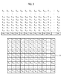
FIG. 3 is an exemplary diagram showing sampling data and pixels of an ultrasound image. -
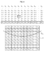
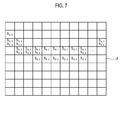
FIGS. 4 to 7 are diagrams showing an example of performing sampling data-oriented beam forming processing in accordance with a first embodiment of the present invention. -
FIG. 8 is an exemplary diagram showing an example of setting weights in accordance with a second embodiment of the present invention. -
FIG. 9 is an exemplary diagram showing an example of setting a sampling data set in accordance with a third embodiment of the present invention. - Hereinafter, embodiments of the present invention will be described by referring to the accompanying drawings.
-
FIG. 1 is a block diagram showing an illustrative embodiment of an ultrasound system. Referring toFIG. 1 , theultrasound system 100 includes an ultrasounddata acquisition unit 110, aprocessor 120, astorage unit 130 and adisplay unit 140. - The ultrasound
data acquisition unit 110 is configured to transmit an ultrasound signal to a target object and receive an ultrasound signal reflected from the target object (i.e., ultrasound echo signal) to thereby acquire ultrasound data. -
FIG. 2 is a block diagram showing an illustrative embodiment of the ultrasounddata acquisition unit 110. Referring toFIG. 2 , the ultrasounddata acquisition unit 100 may include anultrasound probe 210, a transmitsignal forming section 220, abeam forming section 230 and an ultrasounddata forming section 240. - The
ultrasound probe 210 includes a plurality of transducer elements, which are configured to perform reciprocal conversion between an electrical signal and an ultrasound signal. Theultrasound probe 210 is configured to transmit an ultrasound beam along each of multiple scan lines and receive an ultrasound echo signal from the target object to thereby form a receive signal. In one embodiment, the receive signal may be an analog signal. Theultrasound probe 210 includes at least one of a convex probe, a linear probe and the like. - The transmit
signal forming section 220 is configured to control transmission of the ultrasound signal. Also, the transmitsignal forming section 220 is configured to generate transmit signals to obtain an ultrasound image by considering the transducers and focal points. If the transmit signals are provided from the transmitsignal forming section 220, then theultrasound probe 210 may be operable to convert the transmit signal into an ultrasound signal, which is propagated into the target object, and receive an ultrasound echo signal to thereby form a receive signal. - The beaming
section 230 is configured to perform analog-to-digital conversion upon the receive signal, which is provided from theultrasound probe 210, to form sampling data. Also, thebeam forming section 230 is further configured to perform software beam forming upon the sampling data in consideration of the transducer elements and focal points to form receive-focusing data according to one embodiment of the present invention. - According to a first embodiment of the present invention, the
beam forming section 230 is configured to perform analog-to-digital conversion upon the receive signals, which are provided trough a plurality of channels CHk, wherein 1≤k≤N, from theultrasound probe 210 to form sampling data S¡,j, wherein i and j are a positive integer. The sampling data Si,j may be stored in thestorage unit 130. Thebeam forming section 230 may determine positions of a plurality of pixels of an ultrasound image to be formed. Thebeam forming section 230 is configured to select pixels, which the respective sampling data are used as pixel data thereof, based on locations of the transducer elements and orientations of the respective pixels with respect to the transducer elements. That is, thebeam forming section 230 is configured to select the pixels, which the respective sampling data are used as pixel data thereof, during the beam forming processing, based on the locations of the transducer elements and orientations of the respective pixels with respect to the transducer elements. Thebeam forming section 230 may be configured to assign sampling data corresponding to the selected pixels as pixel data in a cumulative manner. - In one embodiment, the
beam forming section 230 is configured to set a curve CV6,3 to select pixels, which the sample data S6,3 are used as pixel data thereof, during the beam forming processing (hereinafter, referred to as "beam forming curve") based on the locations of the transducer elements and orientations of the respective pixels with respect to the transducer elements, as shown inFIG. 4 . Thebeam forming section 230 is configured to select pixels P3,1, P3,2, P4,3, P4,4, P4,5, P4,6, P4,7, P4,8, P4,9, ... P3,N on which the beam forming curve CV6,3 passes among the pixels Pa,b of the ultrasound image UI, wherein 1≤a≤M, 1≤b≤N. Thebeam forming section 230 is configured to assign the sampling data S6,3 to the selected pixles P3,1, P3,2, P4,3, P4,4, P4,5, P4,6, P4,7,P4 ,8, P4,9, ... P3,N, as shown inFIG. 5 . Thereafter, thebeam forming section 230 is configured to set a beam forming curve CV6,4 to select pixels, which the sample data S6,4 are used as pixel data thereof during the beam forming processing, based on the locations of the transducer elements and orientations of the respective pixels with respect to the transducer elements, as shown inFIG. 6 . Thebeam forming section 230 is configured to select pixels P2,1, P3,2, P4,2, P4,3, P4,4, P5,4, P5,5, P5,6, P5,7, P5,8,P4 ,9, P5,9,..., P3,N on which the beam forming curve CV6,4 passes among the pixels Pa,b of the ultrasound image UI. As shown inFIG. 7 , the sampling data S6,4 are assigned to the pixels P2,1, P3,2, P4,2, P4,3, P4,4, P5,4, P5,5, P5,6, P5,7, P5,8, P4,9, P5,9,..., P3,N. In this Way, the respective sampling data, which are used as the pixel data, are cumulatively assigned to the pixels as pixel data. - The
beam forming section 230 is configured to perform beam forming processing (i.e., summing) upon the cumulatively assigned sampling data to the respective pixels Pa,b of the ultrasound image UI to thereby form receive-focused data. - In a second embodiment of the present invention, the
beam forming section 230 is configured to perform analog-to-digital conversion upon the receive signals, which are provided trough a plurality of channels CHk, wherein 1≤k≤N, from theultrasound probe 210 to form sampling data Si,j, wherein i and j are positive integer. The sampling data Si,j may be stored in thestorage unit 130. Thebeam forming section 230 may determine locations of a plurality of pixels of an ultrasound image to be formed. Thebeam forming section 230 is configured to select pixels, which the respective sampling data are used as pixel data thereof, based on locations of the transducer elements and orientations of the respective pixels with respect to the transducer elements. That is, thebeam forming section 230 is configured to detect the pixels, which the respective sampling data are used as pixel data thereof during the beam forming process, based on the locations of the transducer elements and orientations of the respective pixels with respect to the transducer elements. Thebeam forming section 230 may assign sampling data corresponding to the detected pixels as pixel data in a cumulative manner. The beam forming section is further configured to determine pixels existing in the same column among the selected pixels and set weights corresponding to the respective determined pixels. The beam forming section is further configured to apply the weights to the respective pixels. - In one embodiment, the
beam forming section 230 is configured to set a curve CV6,3 to select pixels, which the sample data S6,3 are used as pixel data thereof during the beam forming processing (hereinafter, referred to as "beam forming curve"), based on the locations of the transducer elements and orientations of the respective pixels of the ultrasound image with respect to the transducer elements, as shown inFIG. 4 . Thebeam forming section 230 is configured to select pixels P3,1, P3,2, P4,3, P4,4, P4,5, P4,6, P4,7, P4,8, P4,9, ... P3,N on which the beam forming curve CV6,3 passes among the pixels Pa,b of the ultrasound image UI, wherein 1≤a≤M, 1≤b≤N. Thebeam forming section 230 is configured to assign the sampling data S6,3 to the selected pixels P3,1, P3,2, P4,3, P4,4, P4,5, P4,6, P4,7, P4,8, P4,9, ... P3,N, as shown inFIG. 5 . Thebeam forming section 230 is configured to determine pixels P3,2 and P4,2, which exist in the same column among the selected pixels P3,1, P3,2, P4,3, P4,4, P4,5, P4,6, P4,7, P4,5, P4,9, ... P3,N. As illustrated inFIG. 8 , thebeam forming section 230 is configured to compute distances W1 and W2 from a center of each of the pixels P3,2 and P4,2, which exist in the same column, to the beam forming curve CV6,3 and set a first weight α1 corresponding to the pixel P3,2 based on the distance W1 and a second weight α2 corresponding to the pixel P4,2 based on the distance W2. The first and second weights α1 and α2 may be set to be in proportion to or in inverse proportion to the computed distances. Thebeam forming section 230 is configured to apply the first weight α1 to the sampling data S6,3 assigned to the pixel P3,2 and to apply the second weight α2 to the sampling data S6,3 assigned to the pixel P4,2. The beam forming second 230 is configured to perform the above process upon the remaining sampling data. - The
beam forming section 230 is configured to perform beam forming processing (i.e., summing) upon the cumulatively assigned sampling data to the respective pixels Pa,b of the ultrasound image UI to thereby form receive-focused data. - According to a third embodiment of the present invention, the
beam forming section 230 is configured to perform analog-to-digital conversion upon the receive signals, which are provided trough a plurality of channels CHk, wherein 1≤k≤N, from theultrasound probe 210 to form sampling data Si,j, wherein i and j are positive integer. The sampling data Si,j may be stored in thestorage unit 130. Thebeam forming section 230 is configured to set a sampling data set to select pixels using sampling data Si,j during a beam forming process. - In one embodiment, the
beam forming section 230 is configured to set a sampling data set of S1,1, S1,4,..., S1,t,S 2,1, 52,4,...,S2,t ... Sp,t (denoted by a box) to select pixels, which the sampling data Si,j are used as pixel data thereof during the beam forming process, as shown inFIG. 9 . - The
beam forming section 230 is configured to select pixels, which the respective sample data of the sampling data set are used as pixel data thereof during the beam forming processing, based on the locations of the transducer elements and orientations of the respective pixels of the ultrasound image with respect to the transducer elements. Thebeam forming section 230 is further configured to cumulatively assign the sampling data to the selected pixels in the same manner with the first embodiment or the second embodiment. Thebeam forming section 230 is further configured to perform beam forming processing upon the sampling data, which are cumulatively assigned to each of the pixels of the ultrasound image, to thereby form receive-focused data. - According to a fourth embodiment, the
beam forming section 230 is configured to perform down sampling upon the receive signal, which is provided through a plurality of channels from theprobe 210, to form down-sampled sampling data. As described above, thebeam forming section 230 is configured to select the pixels corresponding to the respective sampling data. That is, thebeam forming section 230 is configured to select the pixels, which the respective sampling data are used as the pixel values thereof during the beam forming processing, based on the locations of the transducers and the orientations of the pixels of the ultrasound image with respect to the ultrasound probe. Thebeam forming section 230 is further configured to cumulatively assign the respective sampling data to the selected pixels in the same manner of the first embodiment or the second embodiment. Thebeam forming section 230 is further configured to perform beam forming processing upon the sampling data, which are cumulatively assigned to the respective pixels, to form receive-focused data. - The ultrasound
data forming section 240 is configured to form ultrasound data corresponding to the ultrasound image by using the receive-focused data, which are provided from thebeam forming section 230. The ultrasound data may be radio frequency data, however, it may be not limited thereto. Also, the ultrasounddata forming section 240 is further configured to perform a variety of data processing (e.g., gain adjustment, etc.), which is necessary for forming the ultrasound data, upon the receive-focused data. - Referring back to
FIG. 1 , theprocessor 120 is coupled to the ultrasounddata acquisition unit 110. Theprocessor 120 may include a central processing unit, a microprocessor, a graphic processing unit and the like. - The
storage unit 130 is configured to store the sampling data formed in the ultrasounddata acquisition unit 110. Also, thestorage unit 130 is further configured to store the ultrasound data acquired in the ultrasounddata acquisition unit 110. - The
display unit 140 is configured to display the ultrasound image formed in theprocessor 120. Thedisplay unit 140 may include a liquid crystal display, an organic light emitting diodes and the like. - Although embodiments have been described with reference to a number of illustrative embodiments thereof, it should be understood that numerous other modifications and embodiments can be devised by those skilled in the art that will fall within the spirit and scope of the principles of this disclosure. More particularly, numerous variations and modifications are possible in the component parts and/or arrangements of the subject combination arrangement within the scope of the disclosure, the drawings and the appended claims. In addition to variations and modifications in the component parts and/or arrangements, alternative uses will also be apparent to those skilled in the art.
Claims (15)
- An ultrasound system for forming an ultrasound image having a plurality of pixels, comprising:an ultrasound data acquisition unit configured to form a receive signal based on an ultrasound signal reflected from a target object, perform analog-to-digital conversion on the receive signal to form sampling data, select pixels, which the respective sampling data are used as pixel values thereof among the plurality of pixels, cumulatively assign the corresponding sampling data to the selected pixels and perform beam forming upon the cumulatively assigned sampling data for the respective pixels to form receive-focused data.
- The ultrasound system of Claim 1, wherein the ultrasound data acquisition unit includes:a transmit signal forming section configured to form transmit signals to acquire the ultrasound image;an ultrasound probe including a plurality of transducer elements and operable to transmit an ultrasound signal to the target object in response to the transmit signals and output the receive signal in response to an ultrasound echo signal reflected from the target obj ect; anda beam forming unit configured to perform the analog-to-digital conversion on the receive signal to form sampling data, select pixels, which the respective sampling data are used as pixel values thereof among the plurality of pixels based on locations of the respective transducer elements and orientations of the pixels with respect to the transducer elements, cumulatively assign the corresponding sampling data to the selected pixels and perform beam forming upon the cumulatively assigned sampling data for the respective pixels to form the receive-focused data
- The ultrasound system of Claim 2, wherein the beam forming section is configured to:set a sampling data set to select the pixels , which the respective sampling data are used as the pixel values thereof among the sampling data during a beam forming process, andselect pixels , which the respective sampling data are used in the sampling data as pixel values thereof among the plurality of pixels based on locations of the respective transducer elements and orientations of the pixels with respect to the transducer elements.
- The ultrasound system of Claim 2, wherein the beam forming section is configured to perform down sampling upon the receive signal to form the sampling data with down-sampled.
- The ultrasound system of any one of Claims 2 to 4, wherein the beam forming section is configured to set a beam forming curve to select the pixels, which the respective sampling data are used as pixel values thereof among the plurality of pixels based on locations of the respective transducer elements and orientations of the pixels with respect to the transducer elements during the beam forming and detect pixels through the beam forming curve passes.
- The ultrasound system of any one of Claim 2 to Claim 4, wherein the beam forming section is further configured to,
set a beam forming curve to select the pixels , which the respective sampling data are used as pixel values thereof among the plurality of pixels based on locations of the respective transducer elements and orientations of the pixels with respect to the transducer elements during the beam forming,
select pixels on which the beam forming curve passes,
determine pixels existing in a same column among the selected pixels,
set weights corresponding to the respective determined pixels, and
apply the weights to the sampling data assigned to the corresponding pixels. - The ultrasound system of Claim 6, wherein the beam forming section is configured to compute distances between centers of the determined pixels the beam forming curve, and apply the weight based on the computed distances.
- The ultrasound system of Claim 7, wherein the weights are set in proportion to or in inverse proportion to the computed distances.
- A method of forming an ultrasound image having a plurality of pixels, comprising:a) transmitting an ultrasound signal to a target object and receiving an ultrasound echo signal reflected from the target object to form a receive signal by using an ultrasound probe having a plurality of transducer elements;b) performing analog-to-digital conversion on the receive signal to form sampling data;c) selecting pixels, which the respective sampling data are used as pixel values thereof among the plurality of pixels, and cumulatively assigning the corresponding sampling data to the selected pixels; andd) performing beam forming upon the cumulatively assigned sampling data for the respective pixels to form receive-focused data.
- The method of Claim 9, wherein the step c) includes selecting pixels, which the respective sampling data are used as pixel values thereof among the plurality of pixels based on locations of the respective transducer elements and orientations of the pixels with respect to the transducer elements, and cumulatively assigning the corresponding sampling data to the selected pixels
- The method of Claim 10, wherein the c) includes:setting a sampling data set to select the pixels, which the respective sampling data are used as the pixel values thereof among the sampling data during a beam forming process, andselecting pixels, which the respective sampling data are used in the sampling data as pixel values thereof among the plurality of pixels based on locations of the respective transducer elements and orientations of the pixels with respect to the transducer elements.
- The method of Claim 10, wherein the step b) includes performing down sampling upon the receive signal to form the sampling data with down-sampled.
- The method of Claim 10, wherein the step c) includes:setting a beam forming curve to select the pixels , which the respective sampling data are used as pixel values thereof among the plurality of pixels based on locations of the respective transducer elements and orientations of the pixels with respect to the transducer elements during the beam forming; andselecting pixels on which the beam forming curve passes.
- The method of Claim 10, wherein the step c) includes:c1) setting a beam forming curve to select the pixels , which the respective sampling data are used as pixel values thereof among the plurality of pixels based on locations of the respective transducer elements and orientations of the pixels with respect to the transducer elements during the beam forming;c2) selecting pixels on which the beam forming curve passes;c3) cumulatively assigning the corresponding sampling data to the selected pixels;c4) determining pixels existing in a same column among the selected pixels;c5) setting weights corresponding to the respective determined pixels, andc6) applying the weights to the sampling data assigned to the corresponding pixels.
- The method of Claim 14, wherein the step c5) includes:computing distances between centers of the determined pixels the beam forming curve; andapplying the weight based on the computed distances.
Applications Claiming Priority (1)
| Application Number | Priority Date | Filing Date | Title |
|---|---|---|---|
| KR1020100129665A KR101231955B1 (en) | 2010-12-17 | 2010-12-17 | Ultrasound system and method for processing beam-forming based on sampling data |
Publications (3)
| Publication Number | Publication Date |
|---|---|
| EP2466330A2 true EP2466330A2 (en) | 2012-06-20 |
| EP2466330A3 EP2466330A3 (en) | 2013-11-13 |
| EP2466330B1 EP2466330B1 (en) | 2019-07-24 |
Family
ID=45554432
Family Applications (1)
| Application Number | Title | Priority Date | Filing Date |
|---|---|---|---|
| EP11193761.1A Active EP2466330B1 (en) | 2010-12-17 | 2011-12-15 | Ultrasound system and method for processing beam-forming based on sampling data |
Country Status (4)
| Country | Link |
|---|---|
| US (1) | US9081084B2 (en) |
| EP (1) | EP2466330B1 (en) |
| JP (1) | JP2012130683A (en) |
| KR (1) | KR101231955B1 (en) |
Cited By (1)
| Publication number | Priority date | Publication date | Assignee | Title |
|---|---|---|---|---|
| EP3248027A4 (en) * | 2015-01-23 | 2018-07-18 | Dalhousie University | Systems and methods for beamforming using variable sampling |
Families Citing this family (4)
| Publication number | Priority date | Publication date | Assignee | Title |
|---|---|---|---|---|
| KR101348772B1 (en) * | 2011-12-29 | 2014-01-07 | 삼성메디슨 주식회사 | Ultrasound system and method for providing doppler spectrum images corresponding to at least two sample volumes |
| US10667790B2 (en) | 2012-03-26 | 2020-06-02 | Teratech Corporation | Tablet ultrasound system |
| US9877699B2 (en) | 2012-03-26 | 2018-01-30 | Teratech Corporation | Tablet ultrasound system |
| CN110167449A (en) | 2016-11-16 | 2019-08-23 | 德拉工业公司 | Portable ultrasound system |
Family Cites Families (8)
| Publication number | Priority date | Publication date | Assignee | Title |
|---|---|---|---|---|
| US6088295A (en) * | 1998-12-29 | 2000-07-11 | The United States Of America As Represented By The Secretary Of The Navy | Feature imaging and adaptive focusing for synthetic aperture processor |
| JP2003061956A (en) | 2001-08-30 | 2003-03-04 | Toshiba Corp | Ultrasound diagnostic apparatus, medical diagnostic apparatus, and image processing method |
| US6592523B2 (en) * | 2001-11-21 | 2003-07-15 | Ge Medical Systems Global Technology Company, Llc | Computationally efficient noise reduction filter for enhancement of ultrasound images |
| PL1874192T3 (en) * | 2005-04-14 | 2017-12-29 | Verasonics, Inc. | Ultrasound imaging system with pixel oriented processing |
| EP1750143A3 (en) | 2005-07-27 | 2009-09-09 | Medison Co., Ltd. | Ultrasound diagnostic system and method of automatically controlling brightness and contrast of a three-dimensional ultrasound image |
| JP5091556B2 (en) | 2007-06-22 | 2012-12-05 | 株式会社東芝 | Ultrasonic diagnostic apparatus and ultrasonic image generation method |
| JP5689315B2 (en) | 2007-08-23 | 2015-03-25 | ヴェラゾニックス,インコーポレーテッド | Adaptive ultrasound image reconstruction based on detection process of local media motion |
| US9117439B2 (en) | 2008-03-13 | 2015-08-25 | Supersonic Imagine | Method and apparatus for ultrasound synthetic imagining |
-
2010
- 2010-12-17 KR KR1020100129665A patent/KR101231955B1/en active Active
-
2011
- 2011-12-15 US US13/327,243 patent/US9081084B2/en active Active
- 2011-12-15 JP JP2011274944A patent/JP2012130683A/en active Pending
- 2011-12-15 EP EP11193761.1A patent/EP2466330B1/en active Active
Non-Patent Citations (1)
| Title |
|---|
| None |
Cited By (2)
| Publication number | Priority date | Publication date | Assignee | Title |
|---|---|---|---|---|
| EP3248027A4 (en) * | 2015-01-23 | 2018-07-18 | Dalhousie University | Systems and methods for beamforming using variable sampling |
| US10989810B2 (en) | 2015-01-23 | 2021-04-27 | Dalhousie University | Systems and methods for beamforming using variable sampling |
Also Published As
| Publication number | Publication date |
|---|---|
| EP2466330B1 (en) | 2019-07-24 |
| KR101231955B1 (en) | 2013-02-08 |
| KR20120068174A (en) | 2012-06-27 |
| US20120157847A1 (en) | 2012-06-21 |
| EP2466330A3 (en) | 2013-11-13 |
| US9081084B2 (en) | 2015-07-14 |
| JP2012130683A (en) | 2012-07-12 |
Similar Documents
| Publication | Publication Date | Title |
|---|---|---|
| US9008383B2 (en) | Enhancing quality of ultrasound image in ultrasound system | |
| US8792690B2 (en) | Enhancing quality of ultrasound spatial compound image based on beam profile in ultrasound system | |
| US8317708B2 (en) | Setting an optimal image parameter in an ultrasound system | |
| EP2444001A1 (en) | Providing an ultrasound spatial compound image based on a phased array probe in an ultrasound system | |
| JP6547612B2 (en) | IMAGE PROCESSING APPARATUS, IMAGE PROCESSING METHOD, AND ULTRASONIC DIAGNOSTIC APPARATUS PROVIDED WITH IMAGE PROCESSING APPARATUS | |
| US20130172745A1 (en) | Providing vector doppler image based on decision data in ultrasound system | |
| EP2302414A2 (en) | Ultrasound system and method of performing measurement on three-dimensional ultrasound image | |
| US20130172749A1 (en) | Providing doppler spectrum images corresponding to at least two sample volumes in ultrasound system | |
| US20170188998A1 (en) | Providing user interface in ultrasound system | |
| US9474510B2 (en) | Ultrasound and system for forming an ultrasound image | |
| EP2444821A2 (en) | Providing an ultrasound spatial compound image based on center lines of ultrasound images in an ultrasound system | |
| US9081084B2 (en) | Ultrasound system and method for processing beam-forming based on sampling data | |
| US9510803B2 (en) | Providing compound image of doppler spectrum images in ultrasound system | |
| US20130165783A1 (en) | Providing motion mode image in ultrasound system | |
| EP2281509B1 (en) | Setting a Sagittal View in an Ultrasound System | |
| JP5767002B2 (en) | Ultrasonic transmission / reception device and fish quantity detection method | |
| JP6712313B2 (en) | Signal processing device and radar device | |
| US20130165792A1 (en) | Forming vector information based on vector doppler in ultrasound system | |
| EP2446827B1 (en) | Providing a body mark in an ultrasound system | |
| EP2281510A1 (en) | Providing a plurality of slice images in an ultrasound system | |
| EP2422704A2 (en) | Providing ultrasound spatial compound images in an ultrasound system | |
| US20110282205A1 (en) | Providing at least one slice image with additional information in an ultrasound system | |
| EP2293098A1 (en) | Steering angle adjustment of scan lines using virtual transducer elements in an ultrasound system | |
| EP2251831A2 (en) | Ultrasound system and method for rendering volume data | |
| JP5936857B2 (en) | Ultrasonic diagnostic apparatus and image processing program thereof |
Legal Events
| Date | Code | Title | Description |
|---|---|---|---|
| PUAI | Public reference made under article 153(3) epc to a published international application that has entered the european phase |
Free format text: ORIGINAL CODE: 0009012 |
|
| AK | Designated contracting states |
Kind code of ref document: A2 Designated state(s): AL AT BE BG CH CY CZ DE DK EE ES FI FR GB GR HR HU IE IS IT LI LT LU LV MC MK MT NL NO PL PT RO RS SE SI SK SM TR |
|
| AX | Request for extension of the european patent |
Extension state: BA ME |
|
| PUAL | Search report despatched |
Free format text: ORIGINAL CODE: 0009013 |
|
| AK | Designated contracting states |
Kind code of ref document: A3 Designated state(s): AL AT BE BG CH CY CZ DE DK EE ES FI FR GB GR HR HU IE IS IT LI LT LU LV MC MK MT NL NO PL PT RO RS SE SI SK SM TR |
|
| AX | Request for extension of the european patent |
Extension state: BA ME |
|
| RIC1 | Information provided on ipc code assigned before grant |
Ipc: G10K 11/34 20060101ALI20131008BHEP Ipc: G01S 7/52 20060101AFI20131008BHEP |
|
| 17P | Request for examination filed |
Effective date: 20140317 |
|
| RBV | Designated contracting states (corrected) |
Designated state(s): AL AT BE BG CH CY CZ DE DK EE ES FI FR GB GR HR HU IE IS IT LI LT LU LV MC MK MT NL NO PL PT RO RS SE SI SK SM TR |
|
| 17Q | First examination report despatched |
Effective date: 20161004 |
|
| STAA | Information on the status of an ep patent application or granted ep patent |
Free format text: STATUS: EXAMINATION IS IN PROGRESS |
|
| REG | Reference to a national code |
Ref country code: DE Ref legal event code: R079 Ref document number: 602011060629 Country of ref document: DE Free format text: PREVIOUS MAIN CLASS: G01S0007520000 Ipc: G01S0015890000 |
|
| GRAP | Despatch of communication of intention to grant a patent |
Free format text: ORIGINAL CODE: EPIDOSNIGR1 |
|
| STAA | Information on the status of an ep patent application or granted ep patent |
Free format text: STATUS: GRANT OF PATENT IS INTENDED |
|
| RIC1 | Information provided on ipc code assigned before grant |
Ipc: G10K 11/34 20060101ALI20190211BHEP Ipc: G01S 7/52 20060101ALI20190211BHEP Ipc: G01S 15/89 20060101AFI20190211BHEP |
|
| INTG | Intention to grant announced |
Effective date: 20190308 |
|
| GRAS | Grant fee paid |
Free format text: ORIGINAL CODE: EPIDOSNIGR3 |
|
| GRAA | (expected) grant |
Free format text: ORIGINAL CODE: 0009210 |
|
| STAA | Information on the status of an ep patent application or granted ep patent |
Free format text: STATUS: THE PATENT HAS BEEN GRANTED |
|
| AK | Designated contracting states |
Kind code of ref document: B1 Designated state(s): AL AT BE BG CH CY CZ DE DK EE ES FI FR GB GR HR HU IE IS IT LI LT LU LV MC MK MT NL NO PL PT RO RS SE SI SK SM TR |
|
| REG | Reference to a national code |
Ref country code: GB Ref legal event code: FG4D |
|
| REG | Reference to a national code |
Ref country code: CH Ref legal event code: EP |
|
| REG | Reference to a national code |
Ref country code: DE Ref legal event code: R096 Ref document number: 602011060629 Country of ref document: DE |
|
| REG | Reference to a national code |
Ref country code: AT Ref legal event code: REF Ref document number: 1158834 Country of ref document: AT Kind code of ref document: T Effective date: 20190815 |
|
| REG | Reference to a national code |
Ref country code: IE Ref legal event code: FG4D |
|
| REG | Reference to a national code |
Ref country code: NL Ref legal event code: MP Effective date: 20190724 |
|
| REG | Reference to a national code |
Ref country code: LT Ref legal event code: MG4D |
|
| REG | Reference to a national code |
Ref country code: AT Ref legal event code: MK05 Ref document number: 1158834 Country of ref document: AT Kind code of ref document: T Effective date: 20190724 |
|
| PG25 | Lapsed in a contracting state [announced via postgrant information from national office to epo] |
Ref country code: NL Free format text: LAPSE BECAUSE OF FAILURE TO SUBMIT A TRANSLATION OF THE DESCRIPTION OR TO PAY THE FEE WITHIN THE PRESCRIBED TIME-LIMIT Effective date: 20190724 Ref country code: SE Free format text: LAPSE BECAUSE OF FAILURE TO SUBMIT A TRANSLATION OF THE DESCRIPTION OR TO PAY THE FEE WITHIN THE PRESCRIBED TIME-LIMIT Effective date: 20190724 Ref country code: NO Free format text: LAPSE BECAUSE OF FAILURE TO SUBMIT A TRANSLATION OF THE DESCRIPTION OR TO PAY THE FEE WITHIN THE PRESCRIBED TIME-LIMIT Effective date: 20191024 Ref country code: HR Free format text: LAPSE BECAUSE OF FAILURE TO SUBMIT A TRANSLATION OF THE DESCRIPTION OR TO PAY THE FEE WITHIN THE PRESCRIBED TIME-LIMIT Effective date: 20190724 Ref country code: AT Free format text: LAPSE BECAUSE OF FAILURE TO SUBMIT A TRANSLATION OF THE DESCRIPTION OR TO PAY THE FEE WITHIN THE PRESCRIBED TIME-LIMIT Effective date: 20190724 Ref country code: LT Free format text: LAPSE BECAUSE OF FAILURE TO SUBMIT A TRANSLATION OF THE DESCRIPTION OR TO PAY THE FEE WITHIN THE PRESCRIBED TIME-LIMIT Effective date: 20190724 Ref country code: BG Free format text: LAPSE BECAUSE OF FAILURE TO SUBMIT A TRANSLATION OF THE DESCRIPTION OR TO PAY THE FEE WITHIN THE PRESCRIBED TIME-LIMIT Effective date: 20191024 Ref country code: PT Free format text: LAPSE BECAUSE OF FAILURE TO SUBMIT A TRANSLATION OF THE DESCRIPTION OR TO PAY THE FEE WITHIN THE PRESCRIBED TIME-LIMIT Effective date: 20191125 Ref country code: FI Free format text: LAPSE BECAUSE OF FAILURE TO SUBMIT A TRANSLATION OF THE DESCRIPTION OR TO PAY THE FEE WITHIN THE PRESCRIBED TIME-LIMIT Effective date: 20190724 |
|
| PG25 | Lapsed in a contracting state [announced via postgrant information from national office to epo] |
Ref country code: LV Free format text: LAPSE BECAUSE OF FAILURE TO SUBMIT A TRANSLATION OF THE DESCRIPTION OR TO PAY THE FEE WITHIN THE PRESCRIBED TIME-LIMIT Effective date: 20190724 Ref country code: IS Free format text: LAPSE BECAUSE OF FAILURE TO SUBMIT A TRANSLATION OF THE DESCRIPTION OR TO PAY THE FEE WITHIN THE PRESCRIBED TIME-LIMIT Effective date: 20191124 Ref country code: GR Free format text: LAPSE BECAUSE OF FAILURE TO SUBMIT A TRANSLATION OF THE DESCRIPTION OR TO PAY THE FEE WITHIN THE PRESCRIBED TIME-LIMIT Effective date: 20191025 Ref country code: RS Free format text: LAPSE BECAUSE OF FAILURE TO SUBMIT A TRANSLATION OF THE DESCRIPTION OR TO PAY THE FEE WITHIN THE PRESCRIBED TIME-LIMIT Effective date: 20190724 Ref country code: ES Free format text: LAPSE BECAUSE OF FAILURE TO SUBMIT A TRANSLATION OF THE DESCRIPTION OR TO PAY THE FEE WITHIN THE PRESCRIBED TIME-LIMIT Effective date: 20190724 Ref country code: AL Free format text: LAPSE BECAUSE OF FAILURE TO SUBMIT A TRANSLATION OF THE DESCRIPTION OR TO PAY THE FEE WITHIN THE PRESCRIBED TIME-LIMIT Effective date: 20190724 |
|
| PG25 | Lapsed in a contracting state [announced via postgrant information from national office to epo] |
Ref country code: TR Free format text: LAPSE BECAUSE OF FAILURE TO SUBMIT A TRANSLATION OF THE DESCRIPTION OR TO PAY THE FEE WITHIN THE PRESCRIBED TIME-LIMIT Effective date: 20190724 |
|
| PG25 | Lapsed in a contracting state [announced via postgrant information from national office to epo] |
Ref country code: EE Free format text: LAPSE BECAUSE OF FAILURE TO SUBMIT A TRANSLATION OF THE DESCRIPTION OR TO PAY THE FEE WITHIN THE PRESCRIBED TIME-LIMIT Effective date: 20190724 Ref country code: DK Free format text: LAPSE BECAUSE OF FAILURE TO SUBMIT A TRANSLATION OF THE DESCRIPTION OR TO PAY THE FEE WITHIN THE PRESCRIBED TIME-LIMIT Effective date: 20190724 Ref country code: RO Free format text: LAPSE BECAUSE OF FAILURE TO SUBMIT A TRANSLATION OF THE DESCRIPTION OR TO PAY THE FEE WITHIN THE PRESCRIBED TIME-LIMIT Effective date: 20190724 Ref country code: PL Free format text: LAPSE BECAUSE OF FAILURE TO SUBMIT A TRANSLATION OF THE DESCRIPTION OR TO PAY THE FEE WITHIN THE PRESCRIBED TIME-LIMIT Effective date: 20190724 |
|
| PG25 | Lapsed in a contracting state [announced via postgrant information from national office to epo] |
Ref country code: IS Free format text: LAPSE BECAUSE OF FAILURE TO SUBMIT A TRANSLATION OF THE DESCRIPTION OR TO PAY THE FEE WITHIN THE PRESCRIBED TIME-LIMIT Effective date: 20200224 Ref country code: SK Free format text: LAPSE BECAUSE OF FAILURE TO SUBMIT A TRANSLATION OF THE DESCRIPTION OR TO PAY THE FEE WITHIN THE PRESCRIBED TIME-LIMIT Effective date: 20190724 Ref country code: CZ Free format text: LAPSE BECAUSE OF FAILURE TO SUBMIT A TRANSLATION OF THE DESCRIPTION OR TO PAY THE FEE WITHIN THE PRESCRIBED TIME-LIMIT Effective date: 20190724 Ref country code: SM Free format text: LAPSE BECAUSE OF FAILURE TO SUBMIT A TRANSLATION OF THE DESCRIPTION OR TO PAY THE FEE WITHIN THE PRESCRIBED TIME-LIMIT Effective date: 20190724 |
|
| REG | Reference to a national code |
Ref country code: DE Ref legal event code: R097 Ref document number: 602011060629 Country of ref document: DE |
|
| PLBE | No opposition filed within time limit |
Free format text: ORIGINAL CODE: 0009261 |
|
| STAA | Information on the status of an ep patent application or granted ep patent |
Free format text: STATUS: NO OPPOSITION FILED WITHIN TIME LIMIT |
|
| PG2D | Information on lapse in contracting state deleted |
Ref country code: IS |
|
| REG | Reference to a national code |
Ref country code: CH Ref legal event code: PL |
|
| 26N | No opposition filed |
Effective date: 20200603 |
|
| REG | Reference to a national code |
Ref country code: BE Ref legal event code: MM Effective date: 20191231 |
|
| PG25 | Lapsed in a contracting state [announced via postgrant information from national office to epo] |
Ref country code: SI Free format text: LAPSE BECAUSE OF FAILURE TO SUBMIT A TRANSLATION OF THE DESCRIPTION OR TO PAY THE FEE WITHIN THE PRESCRIBED TIME-LIMIT Effective date: 20190724 Ref country code: MC Free format text: LAPSE BECAUSE OF FAILURE TO SUBMIT A TRANSLATION OF THE DESCRIPTION OR TO PAY THE FEE WITHIN THE PRESCRIBED TIME-LIMIT Effective date: 20190724 |
|
| GBPC | Gb: european patent ceased through non-payment of renewal fee |
Effective date: 20191215 |
|
| PG25 | Lapsed in a contracting state [announced via postgrant information from national office to epo] |
Ref country code: LU Free format text: LAPSE BECAUSE OF NON-PAYMENT OF DUE FEES Effective date: 20191215 Ref country code: IE Free format text: LAPSE BECAUSE OF NON-PAYMENT OF DUE FEES Effective date: 20191215 Ref country code: GB Free format text: LAPSE BECAUSE OF NON-PAYMENT OF DUE FEES Effective date: 20191215 |
|
| PG25 | Lapsed in a contracting state [announced via postgrant information from national office to epo] |
Ref country code: CH Free format text: LAPSE BECAUSE OF NON-PAYMENT OF DUE FEES Effective date: 20191231 Ref country code: BE Free format text: LAPSE BECAUSE OF NON-PAYMENT OF DUE FEES Effective date: 20191231 Ref country code: LI Free format text: LAPSE BECAUSE OF NON-PAYMENT OF DUE FEES Effective date: 20191231 |
|
| PG25 | Lapsed in a contracting state [announced via postgrant information from national office to epo] |
Ref country code: CY Free format text: LAPSE BECAUSE OF FAILURE TO SUBMIT A TRANSLATION OF THE DESCRIPTION OR TO PAY THE FEE WITHIN THE PRESCRIBED TIME-LIMIT Effective date: 20190724 |
|
| PG25 | Lapsed in a contracting state [announced via postgrant information from national office to epo] |
Ref country code: MT Free format text: LAPSE BECAUSE OF FAILURE TO SUBMIT A TRANSLATION OF THE DESCRIPTION OR TO PAY THE FEE WITHIN THE PRESCRIBED TIME-LIMIT Effective date: 20190724 Ref country code: HU Free format text: LAPSE BECAUSE OF FAILURE TO SUBMIT A TRANSLATION OF THE DESCRIPTION OR TO PAY THE FEE WITHIN THE PRESCRIBED TIME-LIMIT; INVALID AB INITIO Effective date: 20111215 |
|
| PG25 | Lapsed in a contracting state [announced via postgrant information from national office to epo] |
Ref country code: MK Free format text: LAPSE BECAUSE OF FAILURE TO SUBMIT A TRANSLATION OF THE DESCRIPTION OR TO PAY THE FEE WITHIN THE PRESCRIBED TIME-LIMIT Effective date: 20190724 |
|
| PGFP | Annual fee paid to national office [announced via postgrant information from national office to epo] |
Ref country code: DE Payment date: 20251105 Year of fee payment: 15 |
|
| PGFP | Annual fee paid to national office [announced via postgrant information from national office to epo] |
Ref country code: IT Payment date: 20251106 Year of fee payment: 15 |
|
| PGFP | Annual fee paid to national office [announced via postgrant information from national office to epo] |
Ref country code: FR Payment date: 20251111 Year of fee payment: 15 |