EP2466268A2 - Rotation angle detection device - Google Patents
Rotation angle detection device Download PDFInfo
- Publication number
- EP2466268A2 EP2466268A2 EP11193347A EP11193347A EP2466268A2 EP 2466268 A2 EP2466268 A2 EP 2466268A2 EP 11193347 A EP11193347 A EP 11193347A EP 11193347 A EP11193347 A EP 11193347A EP 2466268 A2 EP2466268 A2 EP 2466268A2
- Authority
- EP
- European Patent Office
- Prior art keywords
- rotation angle
- output signal
- sinusoidal signal
- sinusoidal
- sin
- Prior art date
- Legal status (The legal status is an assumption and is not a legal conclusion. Google has not performed a legal analysis and makes no representation as to the accuracy of the status listed.)
- Granted
Links
- 238000001514 detection method Methods 0.000 title claims description 25
- 230000002159 abnormal effect Effects 0.000 claims abstract description 61
- 230000014509 gene expression Effects 0.000 claims description 39
- 230000005856 abnormality Effects 0.000 abstract description 74
- 238000012544 monitoring process Methods 0.000 abstract description 71
- 238000000034 method Methods 0.000 description 9
- 230000015654 memory Effects 0.000 description 8
- 230000007257 malfunction Effects 0.000 description 3
- 230000008569 process Effects 0.000 description 3
- 230000008859 change Effects 0.000 description 2
- 230000007423 decrease Effects 0.000 description 2
- 230000006870 function Effects 0.000 description 2
- 238000012986 modification Methods 0.000 description 1
- 230000004048 modification Effects 0.000 description 1
Images



Classifications
-
- G—PHYSICS
- G01—MEASURING; TESTING
- G01D—MEASURING NOT SPECIALLY ADAPTED FOR A SPECIFIC VARIABLE; ARRANGEMENTS FOR MEASURING TWO OR MORE VARIABLES NOT COVERED IN A SINGLE OTHER SUBCLASS; TARIFF METERING APPARATUS; MEASURING OR TESTING NOT OTHERWISE PROVIDED FOR
- G01D5/00—Mechanical means for transferring the output of a sensing member; Means for converting the output of a sensing member to another variable where the form or nature of the sensing member does not constrain the means for converting; Transducers not specially adapted for a specific variable
- G01D5/12—Mechanical means for transferring the output of a sensing member; Means for converting the output of a sensing member to another variable where the form or nature of the sensing member does not constrain the means for converting; Transducers not specially adapted for a specific variable using electric or magnetic means
- G01D5/244—Mechanical means for transferring the output of a sensing member; Means for converting the output of a sensing member to another variable where the form or nature of the sensing member does not constrain the means for converting; Transducers not specially adapted for a specific variable using electric or magnetic means influencing characteristics of pulses or pulse trains; generating pulses or pulse trains
-
- G—PHYSICS
- G01—MEASURING; TESTING
- G01D—MEASURING NOT SPECIALLY ADAPTED FOR A SPECIFIC VARIABLE; ARRANGEMENTS FOR MEASURING TWO OR MORE VARIABLES NOT COVERED IN A SINGLE OTHER SUBCLASS; TARIFF METERING APPARATUS; MEASURING OR TESTING NOT OTHERWISE PROVIDED FOR
- G01D5/00—Mechanical means for transferring the output of a sensing member; Means for converting the output of a sensing member to another variable where the form or nature of the sensing member does not constrain the means for converting; Transducers not specially adapted for a specific variable
- G01D5/12—Mechanical means for transferring the output of a sensing member; Means for converting the output of a sensing member to another variable where the form or nature of the sensing member does not constrain the means for converting; Transducers not specially adapted for a specific variable using electric or magnetic means
- G01D5/244—Mechanical means for transferring the output of a sensing member; Means for converting the output of a sensing member to another variable where the form or nature of the sensing member does not constrain the means for converting; Transducers not specially adapted for a specific variable using electric or magnetic means influencing characteristics of pulses or pulse trains; generating pulses or pulse trains
- G01D5/24457—Failure detection
- G01D5/24461—Failure detection by redundancy or plausibility
-
- G—PHYSICS
- G01—MEASURING; TESTING
- G01D—MEASURING NOT SPECIALLY ADAPTED FOR A SPECIFIC VARIABLE; ARRANGEMENTS FOR MEASURING TWO OR MORE VARIABLES NOT COVERED IN A SINGLE OTHER SUBCLASS; TARIFF METERING APPARATUS; MEASURING OR TESTING NOT OTHERWISE PROVIDED FOR
- G01D5/00—Mechanical means for transferring the output of a sensing member; Means for converting the output of a sensing member to another variable where the form or nature of the sensing member does not constrain the means for converting; Transducers not specially adapted for a specific variable
- G01D5/26—Mechanical means for transferring the output of a sensing member; Means for converting the output of a sensing member to another variable where the form or nature of the sensing member does not constrain the means for converting; Transducers not specially adapted for a specific variable characterised by optical transfer means, i.e. using infrared, visible, or ultraviolet light
- G01D5/32—Mechanical means for transferring the output of a sensing member; Means for converting the output of a sensing member to another variable where the form or nature of the sensing member does not constrain the means for converting; Transducers not specially adapted for a specific variable characterised by optical transfer means, i.e. using infrared, visible, or ultraviolet light with attenuation or whole or partial obturation of beams of light
- G01D5/34—Mechanical means for transferring the output of a sensing member; Means for converting the output of a sensing member to another variable where the form or nature of the sensing member does not constrain the means for converting; Transducers not specially adapted for a specific variable characterised by optical transfer means, i.e. using infrared, visible, or ultraviolet light with attenuation or whole or partial obturation of beams of light the beams of light being detected by photocells
- G01D5/347—Mechanical means for transferring the output of a sensing member; Means for converting the output of a sensing member to another variable where the form or nature of the sensing member does not constrain the means for converting; Transducers not specially adapted for a specific variable characterised by optical transfer means, i.e. using infrared, visible, or ultraviolet light with attenuation or whole or partial obturation of beams of light the beams of light being detected by photocells using displacement encoding scales
- G01D5/3473—Circular or rotary encoders
Definitions
- the invention relates to a rotation angle detection device that detects the rotation angle of a rotor.
- FIG. 4 shows, by way of example, a conventional rotation angle detection device.
- This rotation angle detection device includes a rotor 1 that has a magnet with two poles, that is, a north (N) pole and a south (S) pole, and two magnetic sensors 11 and 12 that are arranged such that the angular interval, about the rotation axis of the rotor 1, between the magnetic sensors 11 and 12 is 90 degrees.
- the magnetic sensors 11 and 12 output respective sinusoidal signals that have a phase difference of 90 degrees.
- the rotation angle detection device detects the rotation angle of the rotor 1 based on the two sinusoidal signals.
- Japanese Patent Application Publications No. 2008-241411 , No. 2002-213944 , No. 2010-110147 , No. 2006-78392 , and No. 2010-48760 refer to, for example, Japanese Patent Application Publications No. 2008-241411 , No. 2002-213944 , No. 2010-110147 , No. 2006-78392 , and No. 2010-48760 .
- the direction indicated by the arrow in FIG. 4 is the normal rotation direction of the rotor 1.
- the rotation angle of the rotor 1 increases as the rotor 1 rotates in the normal direction, and decreases as the rotor 1 rotates in the reverse direction.
- A1 and A2 each represent an amplitude.
- FIG. 5 illustrates how the output signals V 1 and V2 of the respective magnetic sensors 11 and 12 change as the rotation angle ⁇ of the rotor 1 changes.
- the rotation angle 8 of the rotor 1 may be determined according to, for example, Expression 1 shown below.
- An aspect of the invention relates to a rotation angle detection device that includes a first sensor, a second sensor, and a third sensor that output, respectively, a first sinusoidal signal, a second sinusoidal signal, and a third sinusoidal signal, which are different in phase from each other, according to rotation of a rotor, and that detects a rotation angle of the rotor based on the output signals of the first sensor, the second sensor, and the third sensor.
- the rotation angle detection device includes: a determination unit that determines, based on the first sinusoidal signal, the second sinusoidal signal, and the third sinusoidal signal, whether the first sinusoidal signal, the second sinusoidal signal, and the third sinusoidal signal are each normal or abnormal; and a rotation angle calculation unit that calculates the rotation angle of the rotor based on at least two sinusoidal signals that are among the first sinusoidal signal, the second sinusoidal signal, and the third sinusoidal signal, and that are determined as being normal by the determination unit.
- FIG. 1 is a view schematically showing the configuration of the rotation angle detection device according to the example embodiment of the invention.
- the rotation angle detection device may be used, for example, to detect the rotation angle of a rotor of a brushless motor included in an electric power steering system.
- the rotation angle detection device has, for example, a detection rotor 1 that rotates as the brushless motor runs (will hereinafter be referred to as "rotor 1").
- the rotor 1 has a magnet with two poles, that is, a north (N) pole and a south (S) pole.
- Three magnetic sensors 11, 12, and 13 are provided around the rotor 1 at given intervals along the circumferential direction of the rotor 1. It is to be noted that the three magnetic sensors 11, 12, and 13 will be referred to as “first magnetic sensor 11 ", “second magnetic sensor 12", and “third magnetic sensor 13", respectively, where necessary.
- These magnetic sensors 11, 12, and 13 may each be, for example, a magnetic sensor that includes an element of which the electric characteristics change under the influence of the magnetic field, such as a Hall element and a magnetoresistance element (MR element).
- MR element magnetoresistance element
- the angular interval, about the rotation axis of the rotor 1, between the first magnetic sensor 11 and the second magnetic sensor 12 is ⁇ , which is set to, for example, 30 degrees in this example embodiment.
- the angular interval, about the rotation axis of the rotor 1, between the first magnetic sensor 11 and the third magnetic sensor 13 is ⁇ , which is larger than ⁇ and is set to, for example, 60 degrees in this example embodiment.
- the angular interval, about the rotation axis of the rotor 1, between the second magnetic sensor 12 and the third magnetic sensor 13 is ( ⁇ - ⁇ ), which is 30 degrees in this example embodiment.
- the direction indicated by the arrow in FIG. 1 is the normal rotation direction of the rotor 1.
- the rotation angle of the rotor 1 increases as the rotor 1 rotates in the normal direction, and decreases as the rotor 1 rotates in the reverse direction.
- A1, A2, and A3 each represent an amplitude.
- the output signal V1 of the first magnetic sensor 11, the output signal V2 of the second magnetic sensor 12, and the output signal V3 of the third magnetic sensor 13 are all input into a rotation angle calculation unit 20.
- the rotation angle calculation unit 20 calculates the rotation angle ⁇ of the rotor 1 based on the output signal V 1 of the first magnetic sensor 11, the output signal V2 of the second magnetic sensor 12, and the output signal V3 of the third magnetic sensor 13. It is to be noted that the output signal V1 of the first magnetic sensor 11, the output signal V2 of the second magnetic sensor 12, and the output signal V3 of the third magnetic sensor 13 will hereinafter be referred to as "first output signal V1", “second output signal V2", and "third output signal V3", respectively, where necessary.
- the rotation angle calculation unit 20 is constituted of, for example, a microcomputer that includes a CPU (Central Processing Unit), memories (ROM, RAM, etc.), and so on.
- the rotation angle calculation unit 20 serves as multiple function processing portions when the CPU executes given programs stored in the ROM.
- the multiple function processing portions include a first rotation angle calculation portion 21 (an example of "first rotation angle calculation unit"), a second rotation angle calculation portion 22 (an example of “second rotation angle calculation unit”), a third rotation angle calculation portion 23 (an example of "third rotation angle calculation unit”), an abnormality monitoring portion 24 (an example of "determination unit”), and a final rotation angle calculation portion 25 (an example of "fourth rotation angle calculation unit”).
- cos ⁇ and sin ⁇ are stored in the memory in advance, and Expression 4 is, like Expression 2 above, derived through an expression obtained by developing sin( ⁇ + ⁇ ) using a trigonometric addition formula.
- the third rotation angle calculation portion 23 calculates a third rotation angle ⁇ 3 that corresponds to the rotation angle of the rotor 1, based on the second output signal V2 and the third output signal V3.
- the concept of a method of calculating the third rotation angle ⁇ 3 using the third rotation angle calculation portion 23 will be described.
- the third rotation angle calculation portion 23 calculates the third rotation angle ⁇ 3 by subtracting ⁇ from the calculated rotation angle ⁇ 3 '.
- the second output signal V2 is expressed, using ⁇ ' that is ⁇ + ⁇ , as a sinusoidal signal sin ⁇ '
- the third output signal V3 is expressed, using ⁇ ', as a sinusoidal signal sin( ⁇ ' + ( ⁇ - ⁇ )) that is advanced, by ( ⁇ - ⁇ ), in phase with respect to the sinusoidal signal sin ⁇ '
- the third rotation angle calculation portion 23 generates the signal V 23 according to Expression 6 shown below.
- the third rotation angle calculation portion 23 calculates the third rotation angle ⁇ 3 according to Expression 8 shown below.
- ⁇ 3 ⁇ 3 ⁇ ⁇ - ⁇
- ⁇ is stored in the memory in advance.
- the abnormality monitoring portion 24 determines whether each of the first output signal V1, the second output signal V2, and the third output signal V3 is normal or abnormal, based on the first output signal V1, the second output signal V2, and the third output signal V3.
- the abnormality monitoring portion 24 determines whether the first output signal V1, the second output signal V2, and the third output signal V3 are normal or abnormal based on the first output signal V1, the second output signal V2, and the third output signal V3, and the signal V 12 calculated according to Expression 2, the signal V 13 calculated according to Expression 4, and the signal V 23 calculated according to Expression 6.
- the abnormality monitoring portion 24 detects malfunctions of the respective magnetic sensors 11, 12, and 13. If the magnetic sensors 11, 12, and 13 malfunction, the output signals V1, V2, and V3 are fixed to, for example, 0 (zero), the upper limits thereof, or the lower limits thereof, respectively.
- the concept of the normality-abnormality determination made by the abnormality monitoring portion 24 will be described.
- the first output signal V1 is expressed as sin ⁇
- the abnormality monitoring portion 24 determines that the first output signal V1 and the second output signal V2 are both normal. If the value of V1 2 + V 12 2 is out of the range of 1 ⁇ d, on the other hand, the abnormality monitoring portion 24 determines that there is a possibility that at least one of the first output signal V1 and the second output signal V2 may be presently abnormal.
- the process of determining whether the value of V1 2 + V 12 2 is within the range of 1 ⁇ d is periodically executed at given calculation cycles, and it is determined that there is a possibility that at least one of the first output signal V1 and the second output signal V2 may be presently abnormal, if a state where the value of V1 2 + V 12 2 is out of the range of 1 ⁇ d is successively detected a predetermined number of times or more.
- first determination result where necessary.
- d is a constant that is set to a value within a range, for example, from 0 to 0.1. When d is set to 0, therefore, it is determined whether the value of V1 2 + V 12 2 is 1. When d is set to 0.1, it is determined whether the value of V1 2 + V 12 2 is within a range from 0.9 to 1.1.
- the first output signal V1 is expressed as sin ⁇
- the abnormality monitoring portion 24 determines that the first output signal V1 and the third output signal V3 are both normal if the value of V1 2 + V 13 2 is within the range of 1 ⁇ d (d ⁇ 0), and determines that there is a possibility that at least one of the first output signal V1 and the third output signal V3 may be presently abnormal if the value of V1 2 + V 13 2 is out of the range of 1 ⁇ d.
- the process of determining whether the value of V1 2 + V 13 2 is within the range of 1 ⁇ d is periodically executed at given calculation cycles, and it is determined that there is a possibility that at least one of the first output signal V1 and the third output signal V3 may be presently abnormal, if a state where the value of V1 2 + V 13 2 is out of the range of 1 ⁇ d is successively detected a predetermined number of times or more.
- the result of the determination described above will be referred to as "second determination result" where necessary.
- the second output signal V2 is expressed as sin ⁇ '.
- the abnormality monitoring portion 24 determines that the second output signal V2 and the third output signal V3 are normal if the value of V2 2 + V 23 2 is within the range of 1 ⁇ d (d ⁇ 0), and determines that there is a possibility that at least one of the second output signal V2 and V3 may be presently abnormal if the value of V2 2 + V 23 2 is out of the range of 1 ⁇ d.
- the process of determining whether the value of V2 2 + V 23 2 is within the range of 1 ⁇ d is periodically executed at given calculation cycles, and it is determined that there is a possibility that at least one of the second output signal V2 and the third output signal V3 may be presently abnormal, if a state where the value of V2 2 + V 23 2 is out of the range of 1 ⁇ d is successively detected a predetermined number of times or more.
- the result of the determination described above will be referred to as "third determination result" where necessary.
- the abnormality monitoring portion 24 determines whether each of the first output signal V1, the second output signal V2, and the third output signal V3 is normal or abnormal, based on the first to third determination results.
- the result of this determination made by the abnormality monitoring portion 24 will be referred to as "final determination result” where necessary.
- Table 1 shown below indicates the relations between the final determination results and the first to third determination results.
- the abnormality monitoring portion 24 determines that the output signals V1, V2, and V3 are all normal. On the other hand, if the first to third determination results are all "abnormal” (i.e., results indicating that there is a possibility of an abnormality), the abnormality monitoring portion 24 determines that at least two of the output signals V1, V2, and V3 are abnormal. In this case, the rotation angle can not be calculated, and therefore the motor is stopped.
- the abnormality monitoring portion 24 determines that the first output signal V1 is abnormal and the second output signal V2 and the third output signal V3 are normal. If the first determination result and the third determination result are "abnormal” but the second determination result is "normal”, the abnormality monitoring portion 24 determines that the second output signal V2 is abnormal and the first output signal V1 and the third output signal V3 are normal. Next, if the second determination result and the third determination result are "abnormal” but the first determination result is "normal”, the abnormality monitoring portion 24 determines that the third output signal V3 is abnormal and the first output signal V1 and the second output signal V2 are normal.
- the final rotation angle calculation portion 25 calculates a final rotation angle ⁇ based on the final determination result obtained by the abnormality monitoring portion 24, the first rotation angle ⁇ 1 calculated by the first rotation angle calculation portion 21, the second rotation angle ⁇ 2 calculated by the second rotation angle calculation portion 22, and the third rotation angle ⁇ 3 calculated by the third rotation angle calculation portion 23. Specifically, the final rotation angle calculation portion 25 calculates the final rotation angle ⁇ based on the rotation angles that are among the first rotation angle ⁇ 1 , the second rotation angle ⁇ 2 , and the third rotation angle ⁇ 3 , and that are calculated based on the combination of the output signals determined as being normal by the abnormality monitoring portion 24.
- the final rotation angle calculation portion 25 may determine, as the final rotation angle ⁇ , the average of the median of the first rotation angle ⁇ 1 , the second rotation angle ⁇ 2 , and the third rotation angle ⁇ 3 , and another one of the rotation angles ⁇ 1 , ⁇ 2 , and ⁇ 3 which is closer to the median. Further, if the abnormality monitoring portion 24 determines that the output signals V1, V2, and V3 are all normal, the final rotation angle calculation portion 25 may determine any one of the first rotation angle ⁇ 1 , the second rotation angle ⁇ 2 , and the third rotation angle ⁇ 3 as the final rotation angle ⁇ .
- the final rotation angle calculation portion 25 determines the third rotation angle ⁇ 3 , which is calculated based on the second output signal V2 and the third output signal V3, as the final rotation angle ⁇ . If the abnormality monitoring portion 24 determines that the second output signal V2 is abnormal and the first output signal V 1 and the third output signal V3 are normal, the final rotation angle calculation portion 25 determines the second rotation angle ⁇ 2 , which is calculated based on the first output signal V1 and the third output signal V3, as the final rotation angle ⁇ .
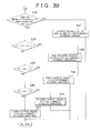
- FIG. 2 is a flowchart illustrating the procedure of the rotation angle calculation routine executed by the rotation angle calculation unit 20.
- the first rotation angle calculation portion 21 calculates the first rotation angle ⁇ 1 by using the output signals V1 and V2, which are read in step S1, and the values of sin ⁇ and cos ⁇ , which are stored in the memory, according to Expressions 2 and 3.
- the second rotation angle calculation portion 22 calculates the second rotation angle ⁇ 2 by using the output signals V1 and V3, which are read in step S1, and the values of sin ⁇ and cos ⁇ , which are stored in the memory, according to Expressions 4 and 5.
- the third rotation angle calculation portion 23 calculates the third rotation angle ⁇ 3 by using the output signals V2 and V3, which are read in step S1, and the values of ⁇ , sin( ⁇ - ⁇ ), and cos( ⁇ - ⁇ ), which are stored in the memory, according to Expressions 6, 7, and 8.
- the abnormality monitoring portion 24 executes an abnormality monitoring process (step S3), which will be described later in detail. If it is determined in the abnormality monitoring process that two or more of the output signals are abnormal (step S4: YES), the abnormality monitoring portion 24 outputs a motor stop command (step S5), so that the motor is stopped. In this case, the rotation angle calculation routine is discontinued.
- the final rotation angle calculation portion 25 calculates the final rotation angle ⁇ based on the first rotation angle ⁇ 1 , the second rotation angle ⁇ 2 , and the third rotation angle ⁇ 3 (step S7). For example, at this time, the final rotation angle calculation portion 25 calculates the average of the first rotation angle ⁇ 1 , the second rotation angle ⁇ 2 , and the third rotation angle ⁇ 3 according to Expression 9 above, and determines the calculated average as the final rotation angle ⁇ . Thereafter, the present cycle of the rotation angle calculation routine is finished.
- the final rotation angle calculation portion 25 determines the third rotation angle ⁇ 3 as the final rotation angle ⁇ (step S9), after which the present cycle of the rotation angle calculation routine is finished. If the abnormality monitoring portion 24 determines that the second output signal V2 is abnormal (step S10: YES), the final rotation angle calculation portion 25 determines the second rotation angle ⁇ 2 as the final rotation angle ⁇ (step S11), after which the present cycle of the rotation angle calculation routine is finished.
- step S10 If the abnormality monitoring portion 24 determines that the third output signal V3 is abnormal (step S10: NO), the final rotation angle calculation portion 25 determines the first rotation angle ⁇ 1 as the final rotation angle ⁇ (step S12), after which the present cycle of the rotation angle calculation routine is finished.
- the abnormality monitoring portion 24 determines whether the value of V1 2 + V 12 2 is within the range of 1 ⁇ d (d ⁇ 0) (step S21). More specifically, at this time, the abnormality monitoring portion 24 determines whether a first condition represented by Expression 10 shown below is satisfied.
- V 12 V ⁇ 2 - V ⁇ 1 ⁇ cos ⁇ sin ⁇
- step S21 If the value of V1 2 + V 12 2 is within the range of 1 ⁇ d (i.e., if the first condition is satisfied) (step S21: YES), the abnormality monitoring portion 24 decrements a first count value K1 by 1 only (-1) (step S22). Then, the abnormality monitoring portion 24 proceeds to step S26. It is to be noted that the initial value of the first count value K1 is 0, and the first count value K1 is an integer of equal to or larger than 0 and does not become a negative value. Therefore, even if the first count value K1 is decremented in step S22, the first count value K1 does not become smaller than 0.
- step S21 if it is determined in this step that the value of V1 2 + V 12 2 is out of the range of 1 ⁇ d (i.e., if the first condition is not satisfied) (step S21: NO), the abnormality monitoring portion 24 increments the first count value K1 by 1 only (+1) (step S23). Then, the abnormality monitoring portion 24 determines whether the first count value K1 is equal to or larger than a predetermined threshold B (step S24). If the first count value K1 is smaller than the threshold B (step S24: NO), the abnormality monitoring portion 24 proceeds to step S26.
- step S24 YES
- step S26 the abnormality monitoring portion 24 determines whether the value of V1 2 + V 13 2 is within the range of 1 ⁇ d (d ⁇ 0). More specifically, at this time, the abnormality monitoring portion 24 determines whether a second condition represented by Expression 11 shown below is satisfied.
- V 13 V ⁇ 3 - V ⁇ 1 ⁇ cos ⁇ sin ⁇
- step S26 If the value of V1 2 + V 13 2 is within the range of 1 ⁇ d (i.e., if the second condition is satisfied) (step S26: YES), the abnormality monitoring portion 24 decrements a second count value K2 by 1 only (-1) (step S27), and then proceeds to step S31. It is to be noted that the initial value of the second count value K2 is 0, and the second count value K2 is an integer of equal to or larger than 0 and does not become a negative value.
- step S26 If it is determined in step S26 that the value of V1 2 + V 13 2 is out of the range of 1 ⁇ d (i.e., if the second condition is not satisfied) (step S26: NO), the abnormality monitoring portion 24 increments the second count value K2 by 1 only (+1) (step S28). Then, the abnormality monitoring portion 24 determines whether the second count value K2 is equal to or larger than the threshold B (step S29). If the second count value K2 is smaller than the threshold B (step S29: NO), the abnormality monitoring portion 24 proceeds to step S31.
- step S29 YES
- step S31 the abnormality monitoring portion 24 determines whether the value of V2 2 + V 23 2 is within the range of 1 ⁇ d (d ⁇ 0). More specifically, at this time, the abnormality monitoring portion 24 determines whether a third condition represented by Expression 12 shown below is satisfied.
- V 23 V ⁇ 3 - V ⁇ 2 ⁇ cos ⁇ - ⁇ sin ⁇ - ⁇
- step S31 If the value of V2 2 + V 23 2 is within the range of 1 ⁇ d (i.e., if the third condition is satisfied) (step S31: YES), the abnormality monitoring portion 24 decrements a third count value K3 by 1 only (-1) (step S32), and then proceeds to step S36. It is to be noted that the initial value of the third count value K3 is 0, and the third count value K3 is an integer of equal to or larger than 0 and does not become a negative value.
- step S31 determines whether the third count value K3 is equal to or larger than the threshold B (step S34). If the third count value K3 is smaller than the threshold B (step S34: NO), the abnormality monitoring portion 24 proceeds to step S36.
- step S34 YES
- step S36 the abnormality monitoring portion 24 determines whether at least two of the first flag F1, the second flag F2, and the third flag F3 are set at 1.
- step S36 If at least two of the first flag F1, the second flag F2, and the third flag F3 are not set at 1 (step S36: NO), that is, if at least two of the first to third determination results are "normal", the abnormality monitoring portion 24 determines that all the output signals V1, V2, and V3 are normal (step S37). Then, the rotation angle calculation unit 20 proceeds to step S4 in the rotation angle calculation routine shown in FIG. 2 .
- step S36 determines whether the flags F1, F2, and F3 are all set at 1 (step S38). If all the flags F1, F2, and F3 are set at 1 (step S38: YES), that is, if the first to third determination results are all "abnormal", the abnormality monitoring portion 24 determines that at least two of the first output signal V1, the second output signal V2, and the third output signal V3 are abnormal (step S39). Then, the rotation angle calculation unit 20 proceeds to step S4 in the rotation angle calculation routine shown in FIG. 2 .
- step S38 determines whether two of the first flag F1, the second flag F2, and the third flag F3 are set at 1 while the remaining one is set at 0 (i.e., the initial value) (step S38: NO).
- the abnormality monitoring portion 24 determines whether the first flag F1 and the second flag F2 are set at 1 (step S40). If the first flag F 1 and the second flag F2 are set at 1 (step S40: YES), that is, if the first and second determination results are "abnormal” and the third determination result is "normal”, the abnormality monitoring portion 24 determines that the first output signal V1 is abnormal (step S41). Then, the rotation angle calculation unit 20 proceeds to step S4 in the rotation angle calculation routine shown in FIG. 2 .
- step S40 determines whether the first flag F1 and the third flag F3 are set at 1 (step S42). If the first flag F1 and the third flag F3 are set at 1 (step S42: YES), that is, if the first and third determination results are "abnormal” and the second determination result is "normal”, the abnormality monitoring portion 24 determines that the second output signal V2 is abnormal (step S43). Then, the rotation angle calculation unit 20 proceeds to step S4 in the rotation angle calculation routine shown in FIG. 2 .
- step S42 determines that one of the first flag F1 and the third flag F3 is not set at 1 (step S42: NO). That is, at this time, the abnormality monitoring portion 24 determines that the second and third determination results are "abnormal" and the first determination result is "normal". In this case, the abnormality monitoring portion 24 determines that the third output signal V3 is abnormal (step S44). Then, the rotation angle calculation unit 20 proceeds to step S4 in the rotation angle calculation routine shown in FIG. 2 .
Landscapes
- Physics & Mathematics (AREA)
- General Physics & Mathematics (AREA)
- Transmission And Conversion Of Sensor Element Output (AREA)
- Measurement Of Length, Angles, Or The Like Using Electric Or Magnetic Means (AREA)
- Combined Controls Of Internal Combustion Engines (AREA)
- Length Measuring Devices With Unspecified Measuring Means (AREA)
Abstract
Description
- The invention relates to a rotation angle detection device that detects the rotation angle of a rotor.
- A brushless motor used in, for example, an electric power steering system is controlled by applying currents to stator coils according to the rotation angle of a rotor.
FIG. 4 shows, by way of example, a conventional rotation angle detection device. This rotation angle detection device includes arotor 1 that has a magnet with two poles, that is, a north (N) pole and a south (S) pole, and twomagnetic sensors rotor 1, between themagnetic sensors magnetic sensors rotor 1 based on the two sinusoidal signals. With regard to such a rotation angle detection device, refer to, for example, Japanese Patent Application Publications No.2008-241411 2002-213944 2010-110147 2006-78392 2010-48760 - The direction indicated by the arrow in
FIG. 4 is the normal rotation direction of therotor 1. The rotation angle of therotor 1 increases as therotor 1 rotates in the normal direction, and decreases as therotor 1 rotates in the reverse direction. As to the rotation angle θ of therotor 1, themagnetic sensor 11 outputs anoutput signal V 1 expressed asV 1 = A1 • sinθ, and themagnetic sensor 12 outputs an output signal V2 expressed as V2 = A2 • sign(θ + 90°) = A2 • cosθ. Note that A1 and A2 each represent an amplitude. - If the amplitudes A1 and A2 are both regarded as being equal to A, or the output signals V1 and V2 are normalized such that the amplitudes A1 and A2 are equal to a predetermined value A, the output signal V1 is expressed as V1 = A • sinθ, and the output signal V2 is expressed as V2 = A • cosθ. Further, if A is 1 (A = 1), the
output signal V 1 is expressed asV 1 = sinθ, and the output signal V2 is expressed as V2 = cosθ. Thus, for facilitating understanding on the following descriptions, theoutput signal V 1 of themagnetic sensor 11 will be expressed as V1 = sinθ, and the output signal V2 of themagnetic sensor 12 will be expressed as V2 = sin(θ + 90°) = cosθ.FIG. 5 illustrates how theoutput signals V 1 and V2 of the respectivemagnetic sensors rotor 1 changes. - The
rotation angle 8 of therotor 1 may be determined according to, for example,Expression 1 shown below.
- However, with the conventional rotation angle detection devices, such as the one described above, the rotation angle is not accurately calculated if one of the magnetic sensors comes to output abnormal output signals.
- It is an object of the invention to provide a rotation angle detection device that, when one of multiple sensors outputs an abnormal signal, identifies the abnormal signal and accurately calculates a rotation angle based on the normal signals output from other sensors.
- An aspect of the invention relates to a rotation angle detection device that includes a first sensor, a second sensor, and a third sensor that output, respectively, a first sinusoidal signal, a second sinusoidal signal, and a third sinusoidal signal, which are different in phase from each other, according to rotation of a rotor, and that detects a rotation angle of the rotor based on the output signals of the first sensor, the second sensor, and the third sensor. The rotation angle detection device includes: a determination unit that determines, based on the first sinusoidal signal, the second sinusoidal signal, and the third sinusoidal signal, whether the first sinusoidal signal, the second sinusoidal signal, and the third sinusoidal signal are each normal or abnormal; and a rotation angle calculation unit that calculates the rotation angle of the rotor based on at least two sinusoidal signals that are among the first sinusoidal signal, the second sinusoidal signal, and the third sinusoidal signal, and that are determined as being normal by the determination unit.
- The foregoing and further features and advantages of the invention will become apparent from the following description of example embodiments with reference to the accompanying drawings, wherein like numerals are used to represent like elements and wherein:
-
FIG. 1 is a view schematically showing the configuration of a rotation angle detection device according to an example embodiment of the invention; -
FIG. 2 is a flowchart illustrating the procedure of a rotation angle calculation routine executed by the rotation angle detection device; -
FIG. 3A and3B are flowcharts together illustrating the procedure of an abnormality monitoring process executed in step S3 in the rotation angle detection routine shown inFIG. 2 ; -
FIG. 4 is a schematic view for describing a rotation angle detection method implemented by a conventional rotation angle detection device; and -
FIG. 5 is a chart schematically illustrating output signals of two magnetic sensors arranged such that the angular interval therebetween is 90 degrees. - Hereafter, an example embodiment of the invention will be described in detail with reference to the accompanying drawings. In the example embodiment, the invention is embodied as a rotation angle detection device that detects the rotation angle of a rotor of a brushless motor.
FIG. 1 is a view schematically showing the configuration of the rotation angle detection device according to the example embodiment of the invention. The rotation angle detection device may be used, for example, to detect the rotation angle of a rotor of a brushless motor included in an electric power steering system. The rotation angle detection device has, for example, adetection rotor 1 that rotates as the brushless motor runs (will hereinafter be referred to as "rotor 1"). Therotor 1 has a magnet with two poles, that is, a north (N) pole and a south (S) pole. Threemagnetic sensors rotor 1 at given intervals along the circumferential direction of therotor 1. It is to be noted that the threemagnetic sensors magnetic sensor 11 ", "secondmagnetic sensor 12", and "thirdmagnetic sensor 13", respectively, where necessary. Thesemagnetic sensors - The angular interval, about the rotation axis of the
rotor 1, between the firstmagnetic sensor 11 and the secondmagnetic sensor 12 is α, which is set to, for example, 30 degrees in this example embodiment. The angular interval, about the rotation axis of therotor 1, between the firstmagnetic sensor 11 and the thirdmagnetic sensor 13 is β, which is larger than α and is set to, for example, 60 degrees in this example embodiment. As a result, the angular interval, about the rotation axis of therotor 1, between the secondmagnetic sensor 12 and the thirdmagnetic sensor 13 is (β - α), which is 30 degrees in this example embodiment. - In this example embodiment, the direction indicated by the arrow in
FIG. 1 is the normal rotation direction of therotor 1. The rotation angle of therotor 1 increases as therotor 1 rotates in the normal direction, and decreases as therotor 1 rotates in the reverse direction. As to the rotation angle θ of therotor 1, the firstmagnetic sensor 11 outputs an output signal V1 expressed asV 1 = A1 • sinθ, and the secondmagnetic sensor 12 outputs an output signal V2 expressed as V2 = A2 • sin(θ + α), and the thirdmagnetic sensor 13 outputs an output signal V3 expressed as V3 = A3 • sin(θ + β). Note that A1, A2, and A3 each represent an amplitude. - If all the amplitudes A1, A2, and A3 are regarded as being equal to A, or the output signals V1, V2, and V3 are normalized such that the amplitudes A1, A2, and A3 are equal to a predetermined value A, the output signals V1, V2, and V3 are expressed as A • sinθ, A • sin(θ + α), and A • sin(θ + β), respectively. Further, if A is 1 (A = 1), the output signal V1 is expressed as sinθ, the output signal V2 is expressed as sin(θ + α), and the output signal V3 is expressed as sin(θ + β). Thus, for facilitating understanding on the following descriptions, the
output signal V 1 of the firstmagnetic sensor 11 will be expressed asV 1 = sinθ, and the output signal V2 of the secondmagnetic sensor 12 will be expressed as V2 = sin(θ + α), and the output signal V3 of the thirdmagnetic sensor 13 will be expressed as V3 = sin(θ + β). - The output signal V1 of the first
magnetic sensor 11, the output signal V2 of the secondmagnetic sensor 12, and the output signal V3 of the thirdmagnetic sensor 13 are all input into a rotationangle calculation unit 20. The rotationangle calculation unit 20 calculates the rotation angle θ of therotor 1 based on theoutput signal V 1 of the firstmagnetic sensor 11, the output signal V2 of the secondmagnetic sensor 12, and the output signal V3 of the thirdmagnetic sensor 13. It is to be noted that the output signal V1 of the firstmagnetic sensor 11, the output signal V2 of the secondmagnetic sensor 12, and the output signal V3 of the thirdmagnetic sensor 13 will hereinafter be referred to as "first output signal V1", "second output signal V2", and "third output signal V3", respectively, where necessary. - The rotation
angle calculation unit 20 is constituted of, for example, a microcomputer that includes a CPU (Central Processing Unit), memories (ROM, RAM, etc.), and so on. The rotationangle calculation unit 20 serves as multiple function processing portions when the CPU executes given programs stored in the ROM. The multiple function processing portions include a first rotation angle calculation portion 21 (an example of "first rotation angle calculation unit"), a second rotation angle calculation portion 22 (an example of "second rotation angle calculation unit"), a third rotation angle calculation portion 23 (an example of "third rotation angle calculation unit"), an abnormality monitoring portion 24 (an example of "determination unit"), and a final rotation angle calculation portion 25 (an example of "fourth rotation angle calculation unit"). - The first rotation
angle calculation portion 21 calculates a first rotation angle θ1 that corresponds to the rotation angle of therotor 1, based on the first output signal V1 and the second output signal V2. More specifically, the first rotationangle calculation portion 21 first generates, based on the first output signal V1 (= sinθ) and the second output signal V2 (= sin(θ + α), a signal V12 (= sin(θ + 90°) = cosθ) that is different in phase from the first output signal V1 by 90 degrees. More specifically, the first rotationangle calculation portion 21 generates the signal V12 according to Expression 2 shown below. -

- As is known from Expression 2, the first rotation
angle calculation portion 21 generates the signal V12 (= cosθ) based on the first output signal V 1 (= sinθ), the second output signal V2 (= sin(θ + α)), cosα, and sinα. Note that cosα and sinα are stored in a given memory in advance, and Expression 2 is derived through an expression obtained by developing sin(θ + α) using a trigonometric addition formula. Then, the first rotationangle calculation portion 21 calculates the first rotation angle θ1 by using the signal V12 (= cosθ) and the first output signal V1 (= sinθ), according to Expression 3 shown below. -

- The second rotation
angle calculation portion 22 calculates a second rotation angle θ2 that corresponds to the rotation angle of therotor 1, based on the first output signal V1 and the third output signal V3. More specifically, the second rotationangle calculation portion 22 first generates, based on the first output signal V1 (= sinθ) and the third output signal V3 (= sin(θ + β)), a signal V13 (= sin(θ + 90°)) = cosθ) that is different in phase from the first output signal V1 by 90 degrees. More specifically, the second rotationangle calculation portion 22 generates the signal V13 according to Expression 4 shown below. -

- As is known from Expression 4, the second rotation
angle calculation portion 22 generates the signal V13 (= cosθ) based on the first output signal V1 (= sinθ), the third output signal V3 (= sin(θ + β)), cosβ, and sinβ. Note that cosβ and sinβ are stored in the memory in advance, and Expression 4 is, like Expression 2 above, derived through an expression obtained by developing sin(θ + β) using a trigonometric addition formula. - Then, the second rotation
angle calculation portion 22 calculates the second rotation angle θ2 by using the signal V13 (= cosθ) and the first output signal V1 (= sinθ), according to Expression 5 shown below. -

- The third rotation
angle calculation portion 23 calculates a third rotation angle θ3 that corresponds to the rotation angle of therotor 1, based on the second output signal V2 and the third output signal V3. The concept of a method of calculating the third rotation angle θ3 using the third rotationangle calculation portion 23 will be described. First, the third rotationangle calculation portion 23 calculates, based on the second output signal V2 and the third output signal V3, a rotation angle θ3' (= θ + α) that is advanced with respect to (larger than) the rotation angle θ of therotor 1 by α. Then, the third rotationangle calculation portion 23 calculates the third rotation angle θ3 by subtracting α from the calculated rotation angle θ3'. - More specifically, the third rotation
angle calculation portion 23 first generates, based on the second output signal V2 (= sin(θ + α)) and the third output signal V3 (= sin(θ + β)), a signal V23 (= sin(θ + α + 90°)) that is different in phase from the second output signal V2 by 90 degrees. If the second output signal V2 is expressed, using θ' that is θ + α, as a sinusoidal signal sinθ', and the third output signal V3 is expressed, using θ', as a sinusoidal signal sin(θ' + (β - α)) that is advanced, by (β - α), in phase with respect to the sinusoidal signal sinθ', the signal V23 (= sin(θ' + 90°) = cosθ') that is different in phase from the sinusoidal signal sinθ' by 90 degrees is obtained in the same method as that used by the first rotationangle calculation portion 21. - More specifically, the third rotation
angle calculation portion 23 generates the signal V23 according to Expression 6 shown below. -

- As is known from Expression 6, the third rotation
angle calculation portion 23 generates the signal V23 (= cosθ') based on the second output signal V2 (= sin(θ + α)), the third output signal V3(sin(θ + β)), cos(β - α), and sin(β - α). Note that cos(β - α) and sin(β - α) are stored in the memory in advance. Then, the third rotationangle calculation portion 23 calculates the rotation angle 03' by using the signal V23 (= cosθ') and the second output signal V2 (= sinθ' = sin(θ + α)), according to Expression 7 shown below. -

- Subsequently, the third rotation
angle calculation portion 23 calculates the third rotation angle θ3 according toExpression 8 shown below.
Note that α is stored in the memory in advance. Theabnormality monitoring portion 24 determines whether each of the first output signal V1, the second output signal V2, and the third output signal V3 is normal or abnormal, based on the first output signal V1, the second output signal V2, and the third output signal V3. More specifically, theabnormality monitoring portion 24 determines whether the first output signal V1, the second output signal V2, and the third output signal V3 are normal or abnormal based on the first output signal V1, the second output signal V2, and the third output signal V3, and the signal V12 calculated according to Expression 2, the signal V13 calculated according to Expression 4, and the signal V23 calculated according to Expression 6. - In other words, the
abnormality monitoring portion 24 detects malfunctions of the respectivemagnetic sensors magnetic sensors abnormality monitoring portion 24 will be described. The first output signal V1 is expressed as sinθ, and the signal V12, which is generated based on the first output signal V1 and the second output signal V2, is expressed as cosθ. Because sinθ2 + cosθ2 is 1 (sinθ2 + cosθ2 = 1), if the first output signal V1 and the second output signal V2 are normal, the condition that V12 + V12 2 = 1 should be satisfied. - Thus, if the value of V12 + V12 2 is within the range of 1 ± d (d ≥ 0), the
abnormality monitoring portion 24 determines that the first output signal V1 and the second output signal V2 are both normal. If the value of V12 + V12 2 is out of the range of 1 ± d, on the other hand, theabnormality monitoring portion 24 determines that there is a possibility that at least one of the first output signal V1 and the second output signal V2 may be presently abnormal. However, it is to be noted that in this example embodiment, the process of determining whether the value of V12 + V12 2 is within the range of 1 ± d is periodically executed at given calculation cycles, and it is determined that there is a possibility that at least one of the first output signal V1 and the second output signal V2 may be presently abnormal, if a state where the value of V12 + V12 2 is out of the range of 1 ± d is successively detected a predetermined number of times or more. In the following, the result of the determination described above will be referred to as "first determination result" where necessary. Note that d is a constant that is set to a value within a range, for example, from 0 to 0.1. When d is set to 0, therefore, it is determined whether the value of V12 + V12 2 is 1. When d is set to 0.1, it is determined whether the value of V12 + V12 2 is within a range from 0.9 to 1.1. - Further, the first output signal V1 is expressed as sinθ, and the signal V13, which is generated based on the first output signal V1 and the third output signal V3, is expressed as cosθ. Because sinθ2 + cosθ2 is 1 (sinθ2 + cosθ2 = 1), if the first output signal V1 and the third output signal V3 are normal, the condition that V12 + V13 2 = 1 should be satisfied. Therefore, the
abnormality monitoring portion 24 determines that the first output signal V1 and the third output signal V3 are both normal if the value of V12 + V13 2 is within the range of 1 ± d (d ≥ 0), and determines that there is a possibility that at least one of the first output signal V1 and the third output signal V3 may be presently abnormal if the value of V12 + V13 2 is out of the range of 1 ± d. However, it is to be noted that in this example embodiment, the process of determining whether the value of V12 + V13 2 is within the range of 1 ± d is periodically executed at given calculation cycles, and it is determined that there is a possibility that at least one of the first output signal V1 and the third output signal V3 may be presently abnormal, if a state where the value of V12 + V13 2 is out of the range of 1 ± d is successively detected a predetermined number of times or more. In the following, the result of the determination described above will be referred to as "second determination result" where necessary. - Further, as mentioned earlier, if θ' is θ + α, (θ' = θ + α), the second output signal V2 is expressed as sinθ'. The signal V23, which is generated based on the second output signal V2 and the third output signal V3, is expressed as cosθ'. Because sinθ'2 + cosθ'2 is 1 (sinθ'2 + cosθ'2 = 1), if the second output signal V2 and the third output signal V3 are normal, the condition that V22 + V23 2 = 1 should be satisfied. For this reason, the
abnormality monitoring portion 24 determines that the second output signal V2 and the third output signal V3 are normal if the value of V22 + V23 2 is within the range of 1 ± d (d ≥ 0), and determines that there is a possibility that at least one of the second output signal V2 and V3 may be presently abnormal if the value of V22 + V23 2 is out of the range of 1 ± d. However, it is to be noted that in this example embodiment, the process of determining whether the value of V22 + V23 2 is within the range of 1 ± d is periodically executed at given calculation cycles, and it is determined that there is a possibility that at least one of the second output signal V2 and the third output signal V3 may be presently abnormal, if a state where the value of V22 + V23 2 is out of the range of 1 ± d is successively detected a predetermined number of times or more. In the following, the result of the determination described above will be referred to as "third determination result" where necessary. - Then, the
abnormality monitoring portion 24 determines whether each of the first output signal V1, the second output signal V2, and the third output signal V3 is normal or abnormal, based on the first to third determination results. The result of this determination made by theabnormality monitoring portion 24 will be referred to as "final determination result" where necessary. Table 1 shown below indicates the relations between the final determination results and the first to third determination results. -
Table 1 First determination result Second determination result Third determination result Final determination result Normal Normal Normal V1, V2, and V3 are all normal Abnormal Abnormal Abnormal At least two output signals are abnormal Abnormal Abnormal Normal V1 is abnormal Abnormal Normal Abnormal V2 is abnormal Normal Abnormal Abnormal V3 is abnormal - As shown in Table 1 above, if the first to third determination results are all "normal" (i.e., results indicating there is no possibility of an abnormality), the
abnormality monitoring portion 24 determines that the output signals V1, V2, and V3 are all normal. On the other hand, if the first to third determination results are all "abnormal" (i.e., results indicating that there is a possibility of an abnormality), theabnormality monitoring portion 24 determines that at least two of the output signals V1, V2, and V3 are abnormal. In this case, the rotation angle can not be calculated, and therefore the motor is stopped. - Next, if the first determination result and the second determination result are "abnormal" but the third determination result is "normal", the
abnormality monitoring portion 24 determines that the first output signal V1 is abnormal and the second output signal V2 and the third output signal V3 are normal. If the first determination result and the third determination result are "abnormal" but the second determination result is "normal", theabnormality monitoring portion 24 determines that the second output signal V2 is abnormal and the first output signal V1 and the third output signal V3 are normal. Next, if the second determination result and the third determination result are "abnormal" but the first determination result is "normal", theabnormality monitoring portion 24 determines that the third output signal V3 is abnormal and the first output signal V1 and the second output signal V2 are normal. - The final rotation
angle calculation portion 25 calculates a final rotation angle θ based on the final determination result obtained by theabnormality monitoring portion 24, the first rotation angle θ1 calculated by the first rotationangle calculation portion 21, the second rotation angle θ2 calculated by the second rotationangle calculation portion 22, and the third rotation angle θ3 calculated by the third rotationangle calculation portion 23. Specifically, the final rotationangle calculation portion 25 calculates the final rotation angle θ based on the rotation angles that are among the first rotation angle θ1, the second rotation angle θ2, and the third rotation angle θ3, and that are calculated based on the combination of the output signals determined as being normal by theabnormality monitoring portion 24. - More specifically, if the
abnormality monitoring portion 24 determines that the output signals V1, V2, and V3 are all normal, the final rotationangle calculation portion 25 calculates the final rotation angle θ according to, for example, Expression 9 shown below. That is, the final rotationangle calculation portion 25 determines the average of the first to third rotation angles θ1, θ2, and θ3 as the final rotation angle θ.
Meanwhile, if theabnormality monitoring portion 24 determines that the output signals V1, V2, and V3 are all normal, the final rotationangle calculation portion 25 may determine the median of the first rotation angle θ1, the second rotation angle θ2, and the third rotation angle θ3 as the final rotation angle θ. Further, if theabnormality monitoring portion 24 determines that the output signals V1, V2, and V3 are all normal, the final rotationangle calculation portion 25 may determine, as the final rotation angle θ, the average of the median of the first rotation angle θ1, the second rotation angle θ2, and the third rotation angle θ3, and another one of the rotation angles θ1, θ2, and θ3 which is closer to the median. Further, if theabnormality monitoring portion 24 determines that the output signals V1, V2, and V3 are all normal, the final rotationangle calculation portion 25 may determine any one of the first rotation angle θ1, the second rotation angle θ2, and the third rotation angle θ3 as the final rotation angle θ. - Next, if the
abnormality monitoring portion 24 determines that the first output signal V1 is abnormal and the second output signal V2 and the third output signal V3 are normal, the final rotationangle calculation portion 25 determines the third rotation angle θ3, which is calculated based on the second output signal V2 and the third output signal V3, as the final rotation angle θ. If theabnormality monitoring portion 24 determines that the second output signal V2 is abnormal and the firstoutput signal V 1 and the third output signal V3 are normal, the final rotationangle calculation portion 25 determines the second rotation angle θ2, which is calculated based on the first output signal V1 and the third output signal V3, as the final rotation angle θ. - If the
abnormality monitoring portion 24 determines that the third output signal V3 is abnormal and the first output signal V1 and the second output signal V2 are normal, the final rotationangle calculation portion 25 determines the first rotation angle θ1, which is calculated based on the first output signal V1 and the second output signal V2, as the final rotation angle θ.FIG. 2 is a flowchart illustrating the procedure of the rotation angle calculation routine executed by the rotationangle calculation unit 20. - The rotation angle calculation routine is periodically executed at given calculation cycles. As shown in
FIG. 2 , first, the rotationangle calculation unit 20 reads the first output signal V 1 (= sinθ) of the firstmagnetic sensor 11, the second output signal V2 (= sin(θ + α)) of the secondmagnetic sensor 12, and the third output signal V3 (= sin(θ + β)) of the third magnetic sensor 13 (step S1). Then, the first rotationangle calculation portion 21, the second rotationangle calculation portion 22, and the third rotationangle calculation portion 23 calculate the first rotation angle θ1, the second rotation angle θ2, ad the third rotation angle θ3, respectively (step S2). That is, at this time, the first rotationangle calculation portion 21 calculates the first rotation angle θ1 by using the output signals V1 and V2, which are read in step S1, and the values of sinα and cosα, which are stored in the memory, according to Expressions 2 and 3. The second rotationangle calculation portion 22 calculates the second rotation angle θ2 by using the output signals V1 and V3, which are read in step S1, and the values of sinβ and cosβ, which are stored in the memory, according to Expressions 4 and 5. The third rotationangle calculation portion 23 calculates the third rotation angle θ3 by using the output signals V2 and V3, which are read in step S1, and the values of α, sin(β - α), and cos(β - α), which are stored in the memory, according toExpressions 6, 7, and 8. - Next, the
abnormality monitoring portion 24 executes an abnormality monitoring process (step S3), which will be described later in detail. If it is determined in the abnormality monitoring process that two or more of the output signals are abnormal (step S4: YES), theabnormality monitoring portion 24 outputs a motor stop command (step S5), so that the motor is stopped. In this case, the rotation angle calculation routine is discontinued. - If it is determined in the abnormality monitoring process that all the output signals V1, V2, and V3 are normal (step S6: YES), the final rotation
angle calculation portion 25 calculates the final rotation angle θ based on the first rotation angle θ1, the second rotation angle θ2, and the third rotation angle θ3 (step S7). For example, at this time, the final rotationangle calculation portion 25 calculates the average of the first rotation angle θ1, the second rotation angle θ2, and the third rotation angle θ3 according to Expression 9 above, and determines the calculated average as the final rotation angle θ. Thereafter, the present cycle of the rotation angle calculation routine is finished. - If the
abnormality monitoring portion 24 determines that the first output signal V1 is abnormal (step S8: YES), the final rotationangle calculation portion 25 determines the third rotation angle θ3 as the final rotation angle θ (step S9), after which the present cycle of the rotation angle calculation routine is finished. If theabnormality monitoring portion 24 determines that the second output signal V2 is abnormal (step S10: YES), the final rotationangle calculation portion 25 determines the second rotation angle θ2 as the final rotation angle θ (step S11), after which the present cycle of the rotation angle calculation routine is finished. - If the
abnormality monitoring portion 24 determines that the third output signal V3 is abnormal (step S10: NO), the final rotationangle calculation portion 25 determines the first rotation angle θ1 as the final rotation angle θ (step S12), after which the present cycle of the rotation angle calculation routine is finished. The flowcharts inFIGs. 3A and3B together illustrate the procedure of the abnormality monitoring process in step S3 in the rotation angle calculation routine illustrated inFIG. 2 . - As shown in
FIG. 3A , first, theabnormality monitoring portion 24 determines whether the value of V12 + V12 2 is within the range of 1 ± d (d ≥ 0) (step S21). More specifically, at this time, theabnormality monitoring portion 24 determines whether a first condition represented by Expression 10 shown below is satisfied. -

- If the value of V12 + V12 2 is within the range of 1 ± d (i.e., if the first condition is satisfied) (step S21: YES), the
abnormality monitoring portion 24 decrements a first count value K1 by 1 only (-1) (step S22). Then, theabnormality monitoring portion 24 proceeds to step S26. It is to be noted that the initial value of the first count value K1 is 0, and the first count value K1 is an integer of equal to or larger than 0 and does not become a negative value. Therefore, even if the first count value K1 is decremented in step S22, the first count value K1 does not become smaller than 0. - On the other hand, referring back to step S21, if it is determined in this step that the value of V12 + V12 2 is out of the range of 1 ± d (i.e., if the first condition is not satisfied) (step S21: NO), the
abnormality monitoring portion 24 increments the first count value K1 by 1 only (+1) (step S23). Then, theabnormality monitoring portion 24 determines whether the first count value K1 is equal to or larger than a predetermined threshold B (step S24). If the first count value K1 is smaller than the threshold B (step S24: NO), theabnormality monitoring portion 24 proceeds to step S26. - On the other hand, if it is determined that the first count value K1 is equal to or larger than the threshold B (step S24: YES), the
abnormality monitoring portion 24 sets a first flag F1 to 1 (F1 = 1) (step S25), and then proceeds to step S26. The first flag F1 is a flag for storing the first determination result, and its initial value is 0 (F1 = 0). In step S26, theabnormality monitoring portion 24 determines whether the value of V12 + V13 2 is within the range of 1 ± d (d ≥ 0). More specifically, at this time, theabnormality monitoring portion 24 determines whether a second condition represented byExpression 11 shown below is satisfied. -

- If the value of V12 + V13 2 is within the range of 1 ± d (i.e., if the second condition is satisfied) (step S26: YES), the
abnormality monitoring portion 24 decrements a second count value K2 by 1 only (-1) (step S27), and then proceeds to step S31. It is to be noted that the initial value of the second count value K2 is 0, and the second count value K2 is an integer of equal to or larger than 0 and does not become a negative value. - If it is determined in step S26 that the value of V12 + V13 2 is out of the range of 1 ± d (i.e., if the second condition is not satisfied) (step S26: NO), the
abnormality monitoring portion 24 increments the second count value K2 by 1 only (+1) (step S28). Then, theabnormality monitoring portion 24 determines whether the second count value K2 is equal to or larger than the threshold B (step S29). If the second count value K2 is smaller than the threshold B (step S29: NO), theabnormality monitoring portion 24 proceeds to step S31. - On the other hand, if it is determined that the second count value K2 is equal to or larger than the threshold B (step S29: YES), the
abnormality monitoring portion 24 sets a second flag F2 to 1 (F2 = 1) (step S30), and then proceeds to step S31. The second flag F2 is a flag for storing the second determination result, and its initial value is 0 (F2 = 0). In step S31, theabnormality monitoring portion 24 determines whether the value of V22 + V23 2 is within the range of 1 ± d (d ≥ 0). More specifically, at this time, theabnormality monitoring portion 24 determines whether a third condition represented byExpression 12 shown below is satisfied. -

- If the value of V22 + V23 2 is within the range of 1 ± d (i.e., if the third condition is satisfied) (step S31: YES), the
abnormality monitoring portion 24 decrements a third count value K3 by 1 only (-1) (step S32), and then proceeds to step S36. It is to be noted that the initial value of the third count value K3 is 0, and the third count value K3 is an integer of equal to or larger than 0 and does not become a negative value. - On the other hand, if it is determined in step S31 that the value of V22 + V23 2 is out of the range of 1 ± d (i.e., if the third condition is not satisfied) (step S31: NO), the
abnormality monitoring portion 24 increments the third count value K3 by 1 only (+1) (step S33). Then, theabnormality monitoring portion 24 determines whether the third count value K3 is equal to or larger than the threshold B (step S34). If the third count value K3 is smaller than the threshold B (step S34: NO), theabnormality monitoring portion 24 proceeds to step S36. - On the other hand, if it is determined that the third count value K3 is equal to or larger than the threshold B (step S34: YES), the
abnormality monitoring portion 24 sets a third flag F3 to 1 (F3 = 1) (step S35), and then proceeds to step S36. The third flag F3 is a flag for storing the third determination result, and its initial value is 0 (F3 = 0). In step S36, theabnormality monitoring portion 24 determines whether at least two of the first flag F1, the second flag F2, and the third flag F3 are set at 1. If at least two of the first flag F1, the second flag F2, and the third flag F3 are not set at 1 (step S36: NO), that is, if at least two of the first to third determination results are "normal", theabnormality monitoring portion 24 determines that all the output signals V1, V2, and V3 are normal (step S37). Then, the rotationangle calculation unit 20 proceeds to step S4 in the rotation angle calculation routine shown inFIG. 2 . - On the other hand, if it is determined in step S36 that at least two of the first flag F1, the second flag F2, and the third flag F3 are set at 1 (step S36: YES), the
abnormality monitoring portion 24 determines whether the flags F1, F2, and F3 are all set at 1 (step S38). If all the flags F1, F2, and F3 are set at 1 (step S38: YES), that is, if the first to third determination results are all "abnormal", theabnormality monitoring portion 24 determines that at least two of the first output signal V1, the second output signal V2, and the third output signal V3 are abnormal (step S39). Then, the rotationangle calculation unit 20 proceeds to step S4 in the rotation angle calculation routine shown inFIG. 2 . - In contrast, if two of the first flag F1, the second flag F2, and the third flag F3 are set at 1 while the remaining one is set at 0 (i.e., the initial value) (step S38: NO), the
abnormality monitoring portion 24 determines whether the first flag F1 and the second flag F2 are set at 1 (step S40). If thefirst flag F 1 and the second flag F2 are set at 1 (step S40: YES), that is, if the first and second determination results are "abnormal" and the third determination result is "normal", theabnormality monitoring portion 24 determines that the first output signal V1 is abnormal (step S41). Then, the rotationangle calculation unit 20 proceeds to step S4 in the rotation angle calculation routine shown inFIG. 2 . - On the other hand, if it is determined in step S40 that one of the first flag F1 and the second flag F2 is not set at 1 (step S40: NO), the
abnormality monitoring portion 24 determines whether the first flag F1 and the third flag F3 are set at 1 (step S42). If the first flag F1 and the third flag F3 are set at 1 (step S42: YES), that is, if the first and third determination results are "abnormal" and the second determination result is "normal", theabnormality monitoring portion 24 determines that the second output signal V2 is abnormal (step S43). Then, the rotationangle calculation unit 20 proceeds to step S4 in the rotation angle calculation routine shown inFIG. 2 . - On the other hand, if it is determined in step S42 that one of the first flag F1 and the third flag F3 is not set at 1 (step S42: NO), the
abnormality monitoring portion 24 determines that the second flag F2 and the third flag F3 are set at 1. That is, at this time, theabnormality monitoring portion 24 determines that the second and third determination results are "abnormal" and the first determination result is "normal". In this case, theabnormality monitoring portion 24 determines that the third output signal V3 is abnormal (step S44). Then, the rotationangle calculation unit 20 proceeds to step S4 in the rotation angle calculation routine shown inFIG. 2 . - According to the foregoing example embodiment, it is possible to detect an output signal abnormality based on the fact that one of the first output signal V1, the second output signal V2, and the third output signal V3 is abnormal, and further identify the abnormal output signal among the output signals V1, V2 and V3. Also, it is possible to calculate the rotation angle θ of the
rotor 1 based on two normal output signals, among the first output signal V1, the second output signal V2, and the third output signal V3, without using the remaining one that is abnormal. Therefore, even if one of the threemagnetic sensors rotor 1 is accurately calculated. - The disclosure has been explained in conjunction with the specific exemplary embodiment thereof. However, it is evident that many alternatives, modifications, and variations will be apparent to those skilled in the art. Accordingly, the examples of the disclosure as set forth herein are intended to be illustrative, not limiting. There are changes that may be made without departing from the scope of the claims. For example, the invention may be applied also to a case where the rotation angles of various rotors other than rotors of brushless motors are detected.
Claims (5)
- A rotation angle detection device that includes a first sensor, a second sensor, and a third sensor that output, respectively, a first sinusoidal signal, a second sinusoidal signal, and a third sinusoidal signal, which are different in phase from each other, according to rotation of a rotor, and that detects a rotation angle of the rotor based on the first, second, and third sinusoidal signals, comprising:a determination unit that determines, based on the first sinusoidal signal, the second sinusoidal signal, and the third sinusoidal signal, whether the first sinusoidal signal, the second sinusoidal signal, and the third sinusoidal signal are each normal or abnormal; anda rotation angle calculation unit that calculates the rotation angle of the rotor based on at least two sinusoidal signals that are among the first sinusoidal signal, the second sinusoidal signal, and the third sinusoidal signal, and that are determined as being normal by the determination unit.
- The rotation angle detection device according to claim 1, wherein
the determination unit comprises:a first determination unit that determines, based on the first and second sinusoidal signals, whether there is a possibility that at least one of the first and second sinusoidal signals is presently abnormal;a second determination unit that determines, based on the first and third sinusoidal signals, whether there is a possibility that at least one of the first and third sinusoidal signals is presently abnormal;a third determination unit that determines, based on the second and third sinusoidal signals, whether there is a possibility that at least one of the second and third sinusoidal signals is presently abnormal; anda fourth determination unit that determines, based on results of determinations made by the first, second, and third determination units, whether the first sinusoidal signal, the second sinusoidal signal, and the third sinusoidal signal are each normal or abnormal. - The rotation angle detection device according to claim 2, wherein:the first sensor is a sensor that outputs, as the first sinusoidal signal, a first sinusoidal signal V1 corresponding to a rotation angle θ as the rotation angle of the rotor, the first sinusoidal signal V1 being expressed as V 1 = sinθ;the second sensor is a sensor that outputs, as the second sinusoidal signal, a second sinusoidal signal V2 corresponding to the rotation angle θ of the rotor, the second sinusoidal signal V2 being expressed as V2 = sin(θ + α) where α represents a phase difference between the first and second sinusoidal signals;the third sensor is a sensor that outputs, as the third sinusoidal signal, a third sinusoidal signal V3 corresponding to the rotation angle θ of the rotor, the third sinusoidal signal V3 being expressed as V3 = sin(θ + β) where β represents a phase difference between the first and third sinusoidal signals;the first determination unit determines whether there is a possibility that at least one of the first and second sinusoidal signals is presently abnormal, based on whether a first condition represented by an expression (i) is satisfied;the second determination unit determines whether there is a possibility that at least one of the first and third sinusoidal signals is presently abnormal, based on whether a second condition represented by an expression (ii) is satisfied; andthe third determination unit determines whether there is a possibility that at least one of the second and third sinusoidal signals is presently abnormal, based on whether a third condition represented by an expression (iii) is satisfied,the first expression (i), the second expression (ii), and the third expression (iii) being


wherein d is a constant of equal to or larger than 0. - The rotation angle detection device according to any one of claims 1 to 3, wherein
the rotation angle calculation unit comprises:a first rotation angle calculation unit that calculates a first rotation angle that corresponds to the rotation angle of the rotor, based on the first and second sinusoidal signals;a second rotation angle calculation unit that calculates a second rotation angle that corresponds to the rotation angle of the rotor, based on the first and third sinusoidal signals;a third rotation angle calculation unit that calculates a third rotation angle that corresponds to the rotation angle of the rotor, based on the second and third sinusoidal signals; anda fourth rotation angle calculation unit that calculates a final rotation angle based on the rotation angles that are among the first rotation angle calculated by the first rotation angle calculation unit, the second rotation angle calculated by the second rotation angle calculation unit, and the third rotation angle calculated by the third rotation angle calculation unit, and that are calculated based on a combination of the sinusoidal signals determined as being normal by the determination unit. - The rotation angle detection device according to claim 4, wherein:the first sensor is a sensor that outputs, as the first sinusoidal signal, a first sinusoidal signal V1 corresponding to a rotation angle θ as the rotation angle of the rotor, the first sinusoidal signal V1 being expressed as V1 = sinθ;the second sensor is a sensor that outputs, as the second sinusoidal signal, a second sinusoidal signal V2 corresponding to the rotation angle θ of the rotor, the second sinusoidal signal V2 being expressed as V2 = sin(θ + α) where α, represents a phase difference between the first and second sinusoidal signals;the third sensor is a sensor that outputs, as the third sinusoidal signal, a third sinusoidal signal V3 corresponding to the rotation angle θ of the rotor, the third sinusoidal signal V3 being expressed as V3 = sin(θ + β) where β represents a phase difference between the first and third sinusoidal signals;the first rotation angle calculation unit calculates, as the first rotation angle, a first rotation angle θ1 according to an expression (iv);he second rotation angle calculation unit calculates, as the second rotation angle, a second rotation angle θ2 according to an expression (v); andthe third rotation angle calculation unit calculates, as the third rotation angle, a third rotation angle θ3 according to an expression (vi),the expression (iv), the expression (v), and the expression (vi) being


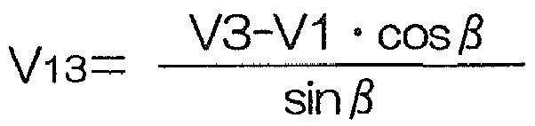


Applications Claiming Priority (1)
| Application Number | Priority Date | Filing Date | Title |
|---|---|---|---|
| JP2010279440A JP5807770B2 (en) | 2010-12-15 | 2010-12-15 | Rotation angle detector |
Publications (3)
| Publication Number | Publication Date |
|---|---|
| EP2466268A2 true EP2466268A2 (en) | 2012-06-20 |
| EP2466268A3 EP2466268A3 (en) | 2014-05-07 |
| EP2466268B1 EP2466268B1 (en) | 2016-04-27 |
Family
ID=45418407
Family Applications (1)
| Application Number | Title | Priority Date | Filing Date |
|---|---|---|---|
| EP11193347.9A Not-in-force EP2466268B1 (en) | 2010-12-15 | 2011-12-13 | Rotation angle detection device |
Country Status (4)
| Country | Link |
|---|---|
| US (1) | US9121729B2 (en) |
| EP (1) | EP2466268B1 (en) |
| JP (1) | JP5807770B2 (en) |
| CN (1) | CN102570943B (en) |
Cited By (5)
| Publication number | Priority date | Publication date | Assignee | Title |
|---|---|---|---|---|
| EP2743645A1 (en) * | 2012-12-12 | 2014-06-18 | JTEKT Corporation | Phase difference detector and rotation angle detection device including the same |
| EP2743644A1 (en) * | 2012-12-12 | 2014-06-18 | JTEKT Corporation | Rotation angle detection device and electric power steering system including the same |
| EP2743643A1 (en) * | 2012-12-12 | 2014-06-18 | Jtekt Corporation | Rotation angle detection device and electric power steering system including the same |
| EP2743647A1 (en) * | 2012-12-12 | 2014-06-18 | JTEKT Corporation | Rotation angle detection device |
| EP2743646A1 (en) * | 2012-12-12 | 2014-06-18 | JTEKT Corporation | Rotation angle detection device |
Families Citing this family (10)
| Publication number | Priority date | Publication date | Assignee | Title |
|---|---|---|---|---|
| JP5660381B2 (en) * | 2011-03-09 | 2015-01-28 | 株式会社ジェイテクト | Rotation angle detector |
| JP2014219364A (en) * | 2013-05-10 | 2014-11-20 | 株式会社ジェイテクト | Rotation angle detection apparatus |
| JP6210284B2 (en) * | 2013-09-18 | 2017-10-11 | 株式会社ジェイテクト | Rotation angle detector |
| US10103607B2 (en) * | 2014-10-20 | 2018-10-16 | Mitsubishi Electric Corporation | Rotation angle detector, rotary electrical machine and elevator hoisting machine |
| JP6664981B2 (en) * | 2016-02-08 | 2020-03-13 | ローム株式会社 | Motor drive |
| JP6354961B2 (en) * | 2016-05-20 | 2018-07-11 | Tdk株式会社 | State determination device and method, physical quantity information generation device, and angle sensor |
| JP6959835B2 (en) * | 2017-11-06 | 2021-11-05 | 株式会社東海理化電機製作所 | Rotation detector |
| KR102557609B1 (en) * | 2017-12-19 | 2023-07-20 | 엘지이노텍 주식회사 | Apparatus for sensing and method for detecting error of the same |
| JP7131281B2 (en) * | 2018-10-11 | 2022-09-06 | 株式会社デンソー | Rotation detector, steering system |
| JP7163842B2 (en) * | 2019-03-28 | 2022-11-01 | 株式会社デンソー | detection unit |
Citations (5)
| Publication number | Priority date | Publication date | Assignee | Title |
|---|---|---|---|---|
| JP2002213944A (en) | 2001-01-18 | 2002-07-31 | Niles Parts Co Ltd | Instrument for measuring rotational angle |
| JP2006078392A (en) | 2004-09-10 | 2006-03-23 | Tamagawa Seiki Co Ltd | Resolver signal error detection method |
| JP2008241411A (en) | 2007-03-27 | 2008-10-09 | Jtekt Corp | Rudder angle detector |
| JP2010048760A (en) | 2008-08-25 | 2010-03-04 | Jtekt Corp | Anomaly detection unit for resolver and electric power steering apparatus |
| JP2010110147A (en) | 2008-10-31 | 2010-05-13 | Jtekt Corp | Motor drive controller and electric power steering device |
Family Cites Families (11)
| Publication number | Priority date | Publication date | Assignee | Title |
|---|---|---|---|---|
| JP2000205811A (en) * | 1999-01-08 | 2000-07-28 | Alps Electric Co Ltd | Rotary sensor |
| JP2001174289A (en) * | 1999-12-17 | 2001-06-29 | Alps Electric Co Ltd | Rotation angle detector |
| JP4143436B2 (en) * | 2003-02-17 | 2008-09-03 | トヨタ自動車株式会社 | Magnetic rotation detector |
| EP1684051A1 (en) * | 2003-11-04 | 2006-07-26 | NSK Ltd. | Controller for electric power-steering apparatus |
| JP4797721B2 (en) * | 2005-10-20 | 2011-10-19 | 株式会社デンソー | Rotation angle detector |
| JP4559982B2 (en) * | 2006-03-02 | 2010-10-13 | 株式会社東海理化電機製作所 | Rotation angle detection device and initial setting method thereof |
| JP4656024B2 (en) * | 2006-08-22 | 2011-03-23 | 株式会社デンソー | Abnormality detection device for rotation angle detection device |
| US8115479B2 (en) * | 2006-11-21 | 2012-02-14 | Hitachi Metals, Ltd. | Rotation-angle-detecting apparatus, rotating machine, and rotation-angle-detecting method |
| JP4858855B2 (en) * | 2006-11-21 | 2012-01-18 | 日立金属株式会社 | Rotation angle detector and rotating machine |
| JP5082482B2 (en) * | 2007-02-13 | 2012-11-28 | 日本精工株式会社 | Rotation information calculation device and motor |
| JP4330083B2 (en) * | 2007-05-18 | 2009-09-09 | 株式会社日本自動車部品総合研究所 | Rotation angle detector |
-
2010
- 2010-12-15 JP JP2010279440A patent/JP5807770B2/en not_active Expired - Fee Related
-
2011
- 2011-12-13 EP EP11193347.9A patent/EP2466268B1/en not_active Not-in-force
- 2011-12-14 CN CN201110418154.9A patent/CN102570943B/en not_active Expired - Fee Related
- 2011-12-15 US US13/326,701 patent/US9121729B2/en not_active Expired - Fee Related
Patent Citations (5)
| Publication number | Priority date | Publication date | Assignee | Title |
|---|---|---|---|---|
| JP2002213944A (en) | 2001-01-18 | 2002-07-31 | Niles Parts Co Ltd | Instrument for measuring rotational angle |
| JP2006078392A (en) | 2004-09-10 | 2006-03-23 | Tamagawa Seiki Co Ltd | Resolver signal error detection method |
| JP2008241411A (en) | 2007-03-27 | 2008-10-09 | Jtekt Corp | Rudder angle detector |
| JP2010048760A (en) | 2008-08-25 | 2010-03-04 | Jtekt Corp | Anomaly detection unit for resolver and electric power steering apparatus |
| JP2010110147A (en) | 2008-10-31 | 2010-05-13 | Jtekt Corp | Motor drive controller and electric power steering device |
Cited By (11)
| Publication number | Priority date | Publication date | Assignee | Title |
|---|---|---|---|---|
| EP2743645A1 (en) * | 2012-12-12 | 2014-06-18 | JTEKT Corporation | Phase difference detector and rotation angle detection device including the same |
| EP2743644A1 (en) * | 2012-12-12 | 2014-06-18 | JTEKT Corporation | Rotation angle detection device and electric power steering system including the same |
| EP2743643A1 (en) * | 2012-12-12 | 2014-06-18 | Jtekt Corporation | Rotation angle detection device and electric power steering system including the same |
| CN103863388A (en) * | 2012-12-12 | 2014-06-18 | 株式会社捷太格特 | Rotation angle detection device and electric power steering system including the same |
| EP2743647A1 (en) * | 2012-12-12 | 2014-06-18 | JTEKT Corporation | Rotation angle detection device |
| EP2743646A1 (en) * | 2012-12-12 | 2014-06-18 | JTEKT Corporation | Rotation angle detection device |
| US9523573B2 (en) | 2012-12-12 | 2016-12-20 | Jtekt Corporation | Rotation angle detection device and electric power steering system including the same |
| US9625249B2 (en) | 2012-12-12 | 2017-04-18 | Jtekt Corporation | Rotation angle detection device and electric power steering system including the same |
| US9638509B2 (en) | 2012-12-12 | 2017-05-02 | Jtekt Corporation | Phase difference detector and rotation angle detection device including the same |
| US9658050B2 (en) | 2012-12-12 | 2017-05-23 | Jtekt Corporation | Rotation angle detection device |
| CN103863388B (en) * | 2012-12-12 | 2017-10-10 | 株式会社捷太格特 | Rotary angle detecting device and the driven steering device for possessing it |
Also Published As
| Publication number | Publication date |
|---|---|
| US20120158340A1 (en) | 2012-06-21 |
| EP2466268B1 (en) | 2016-04-27 |
| US9121729B2 (en) | 2015-09-01 |
| CN102570943A (en) | 2012-07-11 |
| EP2466268A3 (en) | 2014-05-07 |
| CN102570943B (en) | 2015-09-23 |
| JP2012127801A (en) | 2012-07-05 |
| JP5807770B2 (en) | 2015-11-10 |
Similar Documents
| Publication | Publication Date | Title |
|---|---|---|
| EP2466268B1 (en) | Rotation angle detection device | |
| US8587296B2 (en) | Rotation angle detecting device | |
| US8942952B2 (en) | Rotation angle detection apparatus | |
| US8933692B2 (en) | Rotation angle detection device | |
| US9605974B2 (en) | Rotation angle detecting device | |
| US8949068B2 (en) | Rotation angle detection device and electric power steering apparatus using same | |
| US9518844B2 (en) | Rotation angle detection device compromising | |
| US8710831B2 (en) | Rotation angle detecting device | |
| US9097509B2 (en) | Rotation angle sensor | |
| EP2472233A1 (en) | Device for detecting angle of rotation | |
| US8952683B2 (en) | Magnetic out-of-axis angle sensing principle | |
| US8957675B2 (en) | Rotation angle detection device | |
| US20120229126A1 (en) | Rotation angle detection device | |
| US20160041007A1 (en) | Hall Sensor Insensitive to External Magnetic Fields | |
| US20140158453A1 (en) | Rotation angle detection device and electric power steering system including the same | |
| US10101396B2 (en) | Detection of current sensor malfunction | |
| CN100501311C (en) | Angle of rotation sensor especially for electric steering of floor conveyors |
Legal Events
| Date | Code | Title | Description |
|---|---|---|---|
| PUAI | Public reference made under article 153(3) epc to a published international application that has entered the european phase |
Free format text: ORIGINAL CODE: 0009012 |
|
| AK | Designated contracting states |
Kind code of ref document: A2 Designated state(s): AL AT BE BG CH CY CZ DE DK EE ES FI FR GB GR HR HU IE IS IT LI LT LU LV MC MK MT NL NO PL PT RO RS SE SI SK SM TR |
|
| AX | Request for extension of the european patent |
Extension state: BA ME |
|
| PUAL | Search report despatched |
Free format text: ORIGINAL CODE: 0009013 |
|
| AK | Designated contracting states |
Kind code of ref document: A3 Designated state(s): AL AT BE BG CH CY CZ DE DK EE ES FI FR GB GR HR HU IE IS IT LI LT LU LV MC MK MT NL NO PL PT RO RS SE SI SK SM TR |
|
| AX | Request for extension of the european patent |
Extension state: BA ME |
|
| RIC1 | Information provided on ipc code assigned before grant |
Ipc: G01D 5/244 20060101AFI20140331BHEP Ipc: G01D 5/347 20060101ALI20140331BHEP |
|
| 17P | Request for examination filed |
Effective date: 20141029 |
|
| RBV | Designated contracting states (corrected) |
Designated state(s): AL AT BE BG CH CY CZ DE DK EE ES FI FR GB GR HR HU IE IS IT LI LT LU LV MC MK MT NL NO PL PT RO RS SE SI SK SM TR |
|
| 17Q | First examination report despatched |
Effective date: 20150703 |
|
| GRAP | Despatch of communication of intention to grant a patent |
Free format text: ORIGINAL CODE: EPIDOSNIGR1 |
|
| INTG | Intention to grant announced |
Effective date: 20160203 |
|
| GRAS | Grant fee paid |
Free format text: ORIGINAL CODE: EPIDOSNIGR3 |
|
| GRAA | (expected) grant |
Free format text: ORIGINAL CODE: 0009210 |
|
| AK | Designated contracting states |
Kind code of ref document: B1 Designated state(s): AL AT BE BG CH CY CZ DE DK EE ES FI FR GB GR HR HU IE IS IT LI LT LU LV MC MK MT NL NO PL PT RO RS SE SI SK SM TR |
|
| REG | Reference to a national code |
Ref country code: GB Ref legal event code: FG4D |
|
| REG | Reference to a national code |
Ref country code: CH Ref legal event code: EP |
|
| REG | Reference to a national code |
Ref country code: AT Ref legal event code: REF Ref document number: 795311 Country of ref document: AT Kind code of ref document: T Effective date: 20160515 |
|
| REG | Reference to a national code |
Ref country code: IE Ref legal event code: FG4D |
|
| REG | Reference to a national code |
Ref country code: DE Ref legal event code: R096 Ref document number: 602011025878 Country of ref document: DE |
|
| REG | Reference to a national code |
Ref country code: LT Ref legal event code: MG4D |
|
| REG | Reference to a national code |
Ref country code: NL Ref legal event code: MP Effective date: 20160427 |
|
| REG | Reference to a national code |
Ref country code: AT Ref legal event code: MK05 Ref document number: 795311 Country of ref document: AT Kind code of ref document: T Effective date: 20160427 |
|
| PG25 | Lapsed in a contracting state [announced via postgrant information from national office to epo] |
Ref country code: NL Free format text: LAPSE BECAUSE OF FAILURE TO SUBMIT A TRANSLATION OF THE DESCRIPTION OR TO PAY THE FEE WITHIN THE PRESCRIBED TIME-LIMIT Effective date: 20160427 |
|
| PG25 | Lapsed in a contracting state [announced via postgrant information from national office to epo] |
Ref country code: FI Free format text: LAPSE BECAUSE OF FAILURE TO SUBMIT A TRANSLATION OF THE DESCRIPTION OR TO PAY THE FEE WITHIN THE PRESCRIBED TIME-LIMIT Effective date: 20160427 Ref country code: LT Free format text: LAPSE BECAUSE OF FAILURE TO SUBMIT A TRANSLATION OF THE DESCRIPTION OR TO PAY THE FEE WITHIN THE PRESCRIBED TIME-LIMIT Effective date: 20160427 Ref country code: NO Free format text: LAPSE BECAUSE OF FAILURE TO SUBMIT A TRANSLATION OF THE DESCRIPTION OR TO PAY THE FEE WITHIN THE PRESCRIBED TIME-LIMIT Effective date: 20160727 Ref country code: PL Free format text: LAPSE BECAUSE OF FAILURE TO SUBMIT A TRANSLATION OF THE DESCRIPTION OR TO PAY THE FEE WITHIN THE PRESCRIBED TIME-LIMIT Effective date: 20160427 |
|
| REG | Reference to a national code |
Ref country code: FR Ref legal event code: PLFP Year of fee payment: 6 |
|
| PG25 | Lapsed in a contracting state [announced via postgrant information from national office to epo] |
Ref country code: ES Free format text: LAPSE BECAUSE OF FAILURE TO SUBMIT A TRANSLATION OF THE DESCRIPTION OR TO PAY THE FEE WITHIN THE PRESCRIBED TIME-LIMIT Effective date: 20160427 Ref country code: PT Free format text: LAPSE BECAUSE OF FAILURE TO SUBMIT A TRANSLATION OF THE DESCRIPTION OR TO PAY THE FEE WITHIN THE PRESCRIBED TIME-LIMIT Effective date: 20160829 Ref country code: SE Free format text: LAPSE BECAUSE OF FAILURE TO SUBMIT A TRANSLATION OF THE DESCRIPTION OR TO PAY THE FEE WITHIN THE PRESCRIBED TIME-LIMIT Effective date: 20160427 Ref country code: RS Free format text: LAPSE BECAUSE OF FAILURE TO SUBMIT A TRANSLATION OF THE DESCRIPTION OR TO PAY THE FEE WITHIN THE PRESCRIBED TIME-LIMIT Effective date: 20160427 Ref country code: HR Free format text: LAPSE BECAUSE OF FAILURE TO SUBMIT A TRANSLATION OF THE DESCRIPTION OR TO PAY THE FEE WITHIN THE PRESCRIBED TIME-LIMIT Effective date: 20160427 Ref country code: LV Free format text: LAPSE BECAUSE OF FAILURE TO SUBMIT A TRANSLATION OF THE DESCRIPTION OR TO PAY THE FEE WITHIN THE PRESCRIBED TIME-LIMIT Effective date: 20160427 Ref country code: AT Free format text: LAPSE BECAUSE OF FAILURE TO SUBMIT A TRANSLATION OF THE DESCRIPTION OR TO PAY THE FEE WITHIN THE PRESCRIBED TIME-LIMIT Effective date: 20160427 Ref country code: GR Free format text: LAPSE BECAUSE OF FAILURE TO SUBMIT A TRANSLATION OF THE DESCRIPTION OR TO PAY THE FEE WITHIN THE PRESCRIBED TIME-LIMIT Effective date: 20160728 |
|
| PG25 | Lapsed in a contracting state [announced via postgrant information from national office to epo] |
Ref country code: BE Free format text: LAPSE BECAUSE OF FAILURE TO SUBMIT A TRANSLATION OF THE DESCRIPTION OR TO PAY THE FEE WITHIN THE PRESCRIBED TIME-LIMIT Effective date: 20160427 Ref country code: IT Free format text: LAPSE BECAUSE OF FAILURE TO SUBMIT A TRANSLATION OF THE DESCRIPTION OR TO PAY THE FEE WITHIN THE PRESCRIBED TIME-LIMIT Effective date: 20160427 |
|
| REG | Reference to a national code |
Ref country code: DE Ref legal event code: R097 Ref document number: 602011025878 Country of ref document: DE |
|
| PG25 | Lapsed in a contracting state [announced via postgrant information from national office to epo] |
Ref country code: RO Free format text: LAPSE BECAUSE OF FAILURE TO SUBMIT A TRANSLATION OF THE DESCRIPTION OR TO PAY THE FEE WITHIN THE PRESCRIBED TIME-LIMIT Effective date: 20160427 Ref country code: CZ Free format text: LAPSE BECAUSE OF FAILURE TO SUBMIT A TRANSLATION OF THE DESCRIPTION OR TO PAY THE FEE WITHIN THE PRESCRIBED TIME-LIMIT Effective date: 20160427 Ref country code: EE Free format text: LAPSE BECAUSE OF FAILURE TO SUBMIT A TRANSLATION OF THE DESCRIPTION OR TO PAY THE FEE WITHIN THE PRESCRIBED TIME-LIMIT Effective date: 20160427 Ref country code: DK Free format text: LAPSE BECAUSE OF FAILURE TO SUBMIT A TRANSLATION OF THE DESCRIPTION OR TO PAY THE FEE WITHIN THE PRESCRIBED TIME-LIMIT Effective date: 20160427 Ref country code: SK Free format text: LAPSE BECAUSE OF FAILURE TO SUBMIT A TRANSLATION OF THE DESCRIPTION OR TO PAY THE FEE WITHIN THE PRESCRIBED TIME-LIMIT Effective date: 20160427 |
|
| PG25 | Lapsed in a contracting state [announced via postgrant information from national office to epo] |
Ref country code: SM Free format text: LAPSE BECAUSE OF FAILURE TO SUBMIT A TRANSLATION OF THE DESCRIPTION OR TO PAY THE FEE WITHIN THE PRESCRIBED TIME-LIMIT Effective date: 20160427 |
|
| PLBE | No opposition filed within time limit |
Free format text: ORIGINAL CODE: 0009261 |
|
| STAA | Information on the status of an ep patent application or granted ep patent |
Free format text: STATUS: NO OPPOSITION FILED WITHIN TIME LIMIT |
|
| 26N | No opposition filed |
Effective date: 20170130 |
|
| PG25 | Lapsed in a contracting state [announced via postgrant information from national office to epo] |
Ref country code: SI Free format text: LAPSE BECAUSE OF FAILURE TO SUBMIT A TRANSLATION OF THE DESCRIPTION OR TO PAY THE FEE WITHIN THE PRESCRIBED TIME-LIMIT Effective date: 20160427 |
|
| REG | Reference to a national code |
Ref country code: CH Ref legal event code: PL |
|
| GBPC | Gb: european patent ceased through non-payment of renewal fee |
Effective date: 20161213 |
|
| PG25 | Lapsed in a contracting state [announced via postgrant information from national office to epo] |
Ref country code: MC Free format text: LAPSE BECAUSE OF FAILURE TO SUBMIT A TRANSLATION OF THE DESCRIPTION OR TO PAY THE FEE WITHIN THE PRESCRIBED TIME-LIMIT Effective date: 20160427 |
|
| REG | Reference to a national code |
Ref country code: IE Ref legal event code: MM4A |
|
| PG25 | Lapsed in a contracting state [announced via postgrant information from national office to epo] |
Ref country code: LU Free format text: LAPSE BECAUSE OF NON-PAYMENT OF DUE FEES Effective date: 20161213 Ref country code: LI Free format text: LAPSE BECAUSE OF NON-PAYMENT OF DUE FEES Effective date: 20161231 Ref country code: CH Free format text: LAPSE BECAUSE OF NON-PAYMENT OF DUE FEES Effective date: 20161231 |
|
| REG | Reference to a national code |
Ref country code: FR Ref legal event code: PLFP Year of fee payment: 7 |
|
| PG25 | Lapsed in a contracting state [announced via postgrant information from national office to epo] |
Ref country code: IE Free format text: LAPSE BECAUSE OF NON-PAYMENT OF DUE FEES Effective date: 20161213 Ref country code: GB Free format text: LAPSE BECAUSE OF NON-PAYMENT OF DUE FEES Effective date: 20161213 |
|
| PG25 | Lapsed in a contracting state [announced via postgrant information from national office to epo] |
Ref country code: CY Free format text: LAPSE BECAUSE OF FAILURE TO SUBMIT A TRANSLATION OF THE DESCRIPTION OR TO PAY THE FEE WITHIN THE PRESCRIBED TIME-LIMIT Effective date: 20160427 Ref country code: HU Free format text: LAPSE BECAUSE OF FAILURE TO SUBMIT A TRANSLATION OF THE DESCRIPTION OR TO PAY THE FEE WITHIN THE PRESCRIBED TIME-LIMIT; INVALID AB INITIO Effective date: 20111213 |
|
| PG25 | Lapsed in a contracting state [announced via postgrant information from national office to epo] |
Ref country code: IS Free format text: LAPSE BECAUSE OF FAILURE TO SUBMIT A TRANSLATION OF THE DESCRIPTION OR TO PAY THE FEE WITHIN THE PRESCRIBED TIME-LIMIT Effective date: 20160427 Ref country code: MK Free format text: LAPSE BECAUSE OF FAILURE TO SUBMIT A TRANSLATION OF THE DESCRIPTION OR TO PAY THE FEE WITHIN THE PRESCRIBED TIME-LIMIT Effective date: 20160427 Ref country code: TR Free format text: LAPSE BECAUSE OF FAILURE TO SUBMIT A TRANSLATION OF THE DESCRIPTION OR TO PAY THE FEE WITHIN THE PRESCRIBED TIME-LIMIT Effective date: 20160427 |
|
| PG25 | Lapsed in a contracting state [announced via postgrant information from national office to epo] |
Ref country code: BG Free format text: LAPSE BECAUSE OF FAILURE TO SUBMIT A TRANSLATION OF THE DESCRIPTION OR TO PAY THE FEE WITHIN THE PRESCRIBED TIME-LIMIT Effective date: 20160427 |
|
| PG25 | Lapsed in a contracting state [announced via postgrant information from national office to epo] |
Ref country code: MT Free format text: LAPSE BECAUSE OF NON-PAYMENT OF DUE FEES Effective date: 20161213 |
|
| PG25 | Lapsed in a contracting state [announced via postgrant information from national office to epo] |
Ref country code: AL Free format text: LAPSE BECAUSE OF FAILURE TO SUBMIT A TRANSLATION OF THE DESCRIPTION OR TO PAY THE FEE WITHIN THE PRESCRIBED TIME-LIMIT Effective date: 20160427 |
|
| PGFP | Annual fee paid to national office [announced via postgrant information from national office to epo] |
Ref country code: DE Payment date: 20201201 Year of fee payment: 10 Ref country code: FR Payment date: 20201112 Year of fee payment: 10 |
|
| REG | Reference to a national code |
Ref country code: DE Ref legal event code: R119 Ref document number: 602011025878 Country of ref document: DE |
|
| PG25 | Lapsed in a contracting state [announced via postgrant information from national office to epo] |
Ref country code: DE Free format text: LAPSE BECAUSE OF NON-PAYMENT OF DUE FEES Effective date: 20220701 |
|
| PG25 | Lapsed in a contracting state [announced via postgrant information from national office to epo] |
Ref country code: FR Free format text: LAPSE BECAUSE OF NON-PAYMENT OF DUE FEES Effective date: 20211231 |