EP2466080A1 - Valve actuation and rocker arm arrangement - Google Patents
Valve actuation and rocker arm arrangement Download PDFInfo
- Publication number
- EP2466080A1 EP2466080A1 EP10252145A EP10252145A EP2466080A1 EP 2466080 A1 EP2466080 A1 EP 2466080A1 EP 10252145 A EP10252145 A EP 10252145A EP 10252145 A EP10252145 A EP 10252145A EP 2466080 A1 EP2466080 A1 EP 2466080A1
- Authority
- EP
- European Patent Office
- Prior art keywords
- rocker arm
- rocker
- arrangement
- valve
- shaft
- Prior art date
- Legal status (The legal status is an assumption and is not a legal conclusion. Google has not performed a legal analysis and makes no representation as to the accuracy of the status listed.)
- Withdrawn
Links
- 238000002485 combustion reaction Methods 0.000 claims abstract description 12
- 229910003460 diamond Inorganic materials 0.000 description 2
- 239000010432 diamond Substances 0.000 description 2
- 230000007246 mechanism Effects 0.000 description 2
- 229910001018 Cast iron Inorganic materials 0.000 description 1
- 229910000831 Steel Inorganic materials 0.000 description 1
- 230000004913 activation Effects 0.000 description 1
- 238000004519 manufacturing process Methods 0.000 description 1
- 230000000737 periodic effect Effects 0.000 description 1
- 239000010959 steel Substances 0.000 description 1
Images


Classifications
-
- F—MECHANICAL ENGINEERING; LIGHTING; HEATING; WEAPONS; BLASTING
- F01—MACHINES OR ENGINES IN GENERAL; ENGINE PLANTS IN GENERAL; STEAM ENGINES
- F01L—CYCLICALLY OPERATING VALVES FOR MACHINES OR ENGINES
- F01L1/00—Valve-gear or valve arrangements, e.g. lift-valve gear
- F01L1/26—Valve-gear or valve arrangements, e.g. lift-valve gear characterised by the provision of two or more valves operated simultaneously by same transmitting-gear; peculiar to machines or engines with more than two lift-valves per cylinder
-
- F—MECHANICAL ENGINEERING; LIGHTING; HEATING; WEAPONS; BLASTING
- F01—MACHINES OR ENGINES IN GENERAL; ENGINE PLANTS IN GENERAL; STEAM ENGINES
- F01L—CYCLICALLY OPERATING VALVES FOR MACHINES OR ENGINES
- F01L1/00—Valve-gear or valve arrangements, e.g. lift-valve gear
- F01L1/12—Transmitting gear between valve drive and valve
- F01L1/18—Rocking arms or levers
- F01L1/181—Centre pivot rocking arms
-
- F—MECHANICAL ENGINEERING; LIGHTING; HEATING; WEAPONS; BLASTING
- F01—MACHINES OR ENGINES IN GENERAL; ENGINE PLANTS IN GENERAL; STEAM ENGINES
- F01L—CYCLICALLY OPERATING VALVES FOR MACHINES OR ENGINES
- F01L1/00—Valve-gear or valve arrangements, e.g. lift-valve gear
- F01L1/12—Transmitting gear between valve drive and valve
- F01L1/14—Tappets; Push rods
- F01L1/146—Push-rods
Definitions
- This disclosure is directed to a valve actuation and rocker arm arrangement for an internal combustion engine.
- Internal combustion engines generally comprise a number of cylinders, each with at least one intake valve and at least one exhaust valve.
- a common arrangement is for each cylinder to have two intake valves and two exhaust valves, with the valves being actuated via a rocker arm and cam arrangement. Alternatively, there may be two of one type of valve and one of the other.
- Overhead valve engines are internal combustion engines wherein the intake and exhaust valves are located in the cylinder head, while the camshaft may be placed in the cylinder block.
- the valves may be actuated by the camshaft through the intermediation of lifters (also known as tappets), push rods, and rocker arms, in that order.
- lifters also known as tappets
- push rods push rods
- rocker arms rocker arms
- the rocker arms for the intake and exhaust valves use a common rocker shaft in order to reduce the weight and space required for the mechanism.
- Such an arrangement is disclosed in WO-A-2010/057648 .
- a square valve pattern may be employed.
- the intake and exhaust valves are disposed on the side of the cylinder head closest to their respective ports.
- a rocker arm arrangement (30) for an internal combustion engine comprising:
- valve actuation arrangement (10) for an internal combustion engine comprising:
- rocker arm arrangement for an internal combustion engine is as described with reference to, and as shown in the accompanying drawings.
- FIG. 1 illustrates a valve actuation arrangement 10 for an internal combustion engine (not shown) including a rocker arm arrangement 30 as described in further detail below.
- the valve actuation arrangement 10 shown is in the form of a valve train 10 suitable for use in an overhead valve engine with a substantially square shaped valve configuration.
- the valve train 10 is depicted as a valve train for a four-cylinder, four-stroke, inline internal combustion engine, having four valves per cylinder.
- valve trains comprising the valve actuation 10 and rocker arm 30 arrangements described below may be used in many other types of overhead valve engines with any number of cylinders in any configuration, for example an inline or V-configuration.
- the valve train 10 may include a camshaft 11 of a conventional design, having cam lobes 12.
- the depicted camshaft 11 features eight cam lobes 12, two for each cylinder of the four-cylinder engine with which valve train 10 may be used.
- Lifters 13, such as hydraulic tappets, may abut camshaft 11 where cam lobes 12 are provided, so that a rotating motion of the camshaft 11 results in periodic activation of the lifters 13.
- Each lifter 13 may support a first end of an elongate push rod 18.
- a second end of the push rod 18 may normally be in contact with a first end 34,38 of an associated rocker arm 31,35.
- the operable connection between the second end of the push rod 18 and the first end 34,38 of the rocker arm 31,35 may be secured by a push rod retainer 23.
- the rocker arms 31,35 are pivotably mounted on a rocker shaft 39.
- Actuation ends of a rocker arm 31,35, located opposite the first ends 34,38, may mechanically operate a pair of valves 19,20.
- Each valve 19,20 may be provided at an end of a valve stem 15 that may be slidably mounted within a valve stem guide 16.
- An upper end of each valve stem 15 may be connected to a valve spring 17 to bias the valve 19,20 towards its closed position, in touch with a valve seat (not shown).
- camshaft 11 may be an overhead camshaft that acts on the upper surface of rocker arm 31,35.
- FIGs 2 to 4 show the rocker arm arrangement 30 used in the valve actuation arrangement 10 of Figure 1 .
- the rocker arm arrangement 30 may be disposed to actuate two inlet and two exhaust valves 19,20 in a substantially square valve arrangement.
- the two sets of valves 19,20 may be operated by two rocker arms 31 and 35.
- the rocker arms 31 and 35 may be pivotally mounted on a common rocker shaft 39.
- the substantially square shape formed by the valves 19,20 may be oriented such that two of its edges lie parallel to a longitudinal axis 40 of rocker shaft 39 and two of its edges lie perpendicular to longitudinal axis 40 of rocker shaft 39.
- One set of valves 19,20 may comprise the two valves 19 that are more closely disposed to rocker shaft 39, and the other set of valves 19,20 may comprise the two valves 20 that are more remotely disposed to rocker shaft 39.
- Either one of the sets of valves 19,20 may be inlet valves, and the other set may be exhaust valves.
- Each set of inlet/exhaust valves 19 proximal to the rocker shaft 39 may be actuated by a first rocker arm 31.
- the first rocker arm 31 may have a 'split' configuration, namely a generally forked, Y- or C-shaped configuration comprising a connecting body 32, from which project two actuating levers 33, the ends of which each actuate one valve.
- the two actuating levers 33 may project in opposing directions from the connecting body 32.
- a cylindrical bore (not shown) may be provided through the body 32 to enable the pivotal mounting of the first rocker arm 31 on the rocker shaft 39.
- the first rocker arm 31 may further comprise a single point of adjustment 34, to enable the actuation of the levers 33.
- the single point of adjustment 34 may be in the form of a protrusion 34 extending from the body 32 in an opposing direction to that of the actuating levers 33.
- the protrusion 34 may have a bore 42 through it to facilitate the actuation.
- the first rocker arm 31 pivots about rocker shaft 39, and may be driven by a pushrod 18, which may in turn be driven by the camshaft 11.
- Each set of inlet/exhaust valves 20 distal to the rocker shaft 39 may be actuated by a second rocker arm 35.
- the second rocker arm 35 may also have a 'split' configuration, again being a generally forked, Y- or C-shaped configuration comprising a connecting body 36, from which project two actuating levers 37, the ends of which each actuate one valve.
- the two actuating levers 37 may project in opposing directions from the connecting body 36.
- a cylindrical bore 41 through the body 36 may enable the pivotal mounting of the second rocker arm 35 on the rocker shaft 39.
- the second rocker arm 35 may further comprise a single point of adjustment, to enable the actuation of the levers 37.
- the single point of adjustment may be in the form of a protrusion 38 extending from the body 36 in an opposing direction to that of the actuating levers 37.
- the protrusion 38 may have a bore 43 through it to facilitate the actuation.
- the second rocker arm 35 also pivots about rocker shaft 39, and may be driven by a pushrod 18, which may in turn be driven by the camshaft 11.
- the first rocker arm 31 may be nested within the second rocker arm 35, such that the connecting body 32 of the first rocker arm 31 is positioned within and is substantially surrounded by the connecting body 36 of the second rocker arm 35.
- the two rocker arms 31, 35 may lie in substantially the same plane when not actuated by their respective pushrods.
- the actuating levers 37 of the second rocker arm 35 may be arcuate and may extend around the actuating levers 33 of the first rocker arm 31. This enables a substantially square valve arrangement to be achieved using two rocker arms 31, 35 disposed on a common rocker shaft 39.
- the actuating levers 37 of the second rocker arm 35 may extend around the connecting body 32 of the first rocker arm 31. The ends of the actuating levers 33 of the first rocker arm 31 may then protrude past the ends of the actuating levers 37 of the second rocker arm 35.
- first rocker arm 31 may be replaced by an individual rocker arm which may actuate a single inlet/exhaust valve.
- second rocker arm 35 may be replaced by an individual rocker arm which may actuate a single inlet/exhaust valve.
- the actuating lever of the second rocker arm 35 may be arcuate and extend around the actuating lever, or at least one of the actuating levers, of the first rocker arm 31.
- the second rocker arm 35 may be nested within the first rocker arm 31, such that the connecting body 36 of the second rocker arm 35 is positioned within and is substantially surrounded by the connecting body 32 of the first rocker arm 31.
- This embodiment may co-operate with any of the previous embodiments with respect to the number and the arrangement of the actuating levers.
- Rocker arms 31, 35 may be made from cast iron.
- Shaft 39 may be made from steel, which may be heat treated.
- the disclosure has industrial applicability in the manufacture and operation of valve trains for internal combustion engines.
- the camshaft 11 with the cam lobes 12 may rotate, which in turn may cause the lifters 13 to move the push rods 18 reciprocally upward and downward.
- the first end of the associated rocker arm 31,35 may move up accordingly, and may cause the rocker arm to pivot around the rocker shaft 39.
- the pivoting motion of the rocker arm 31,35 may be such that the actuating levers 33,37 of the rocker arm 31,35 may move downward, thereby displacing a set of inlet/exhaust valves 19,20 from their valve seats (not shown), by pressing on their respective valve stems 15 against the action of the valve springs 17.
- the push rod 18 may then move downward as the upward force on the push rod 18 is relieved and thus valve spring 17 may force the rocker arm 31,35 back into its starting position, thereby closing the valves 19,20.
Landscapes
- Engineering & Computer Science (AREA)
- Mechanical Engineering (AREA)
- General Engineering & Computer Science (AREA)
- Valve-Gear Or Valve Arrangements (AREA)
Abstract
This disclosure is directed to a valve actuation and rocker arm arrangement for an internal combustion engine. The rocker arm arrangement (30) comprises a first rocker arm (31) and a second rocker arm (35), wherein the first (31) and second (35) rocker arms are pivotally mountable on a rocker shaft (39) and one of the first (31) or second (35) rocker arms is configured to be positioned within the other of the of the first (31) or second (35) rocker arms. The valve actuation arrangement (10) comprises a rocker arm arrangement (30) according to the disclosure, at least one inlet valve actuable by one of the first (31) or second (35) rocker arms, and at least one exhaust valve actuable by the other of the first (31) or second (35) rocker arms.
Description
- This disclosure is directed to a valve actuation and rocker arm arrangement for an internal combustion engine.
- Internal combustion engines generally comprise a number of cylinders, each with at least one intake valve and at least one exhaust valve. A common arrangement is for each cylinder to have two intake valves and two exhaust valves, with the valves being actuated via a rocker arm and cam arrangement. Alternatively, there may be two of one type of valve and one of the other.
- Overhead valve engines are internal combustion engines wherein the intake and exhaust valves are located in the cylinder head, while the camshaft may be placed in the cylinder block. In such an arrangement, the valves may be actuated by the camshaft through the intermediation of lifters (also known as tappets), push rods, and rocker arms, in that order. The valves and their associated mechanisms make up the valve train.
- Preferably, the rocker arms for the intake and exhaust valves use a common rocker shaft in order to reduce the weight and space required for the mechanism. Such an arrangement is disclosed in
WO-A-2010/057648 . - Many engines utilise a diamond configuration for the intake and exhaust valves. Such an arrangement aids the use of a common rocker shaft. However, this configuration can lead to throttling of the intake and exhaust ports, as the width of each of the ports is restricted due to the orientation of the port and its needing to navigate between cylinder head bolt bosses, pushrod apertures and other restrictions to reach the valves.
- Instead of a diamond valve configuration, a square valve pattern may be employed. In a square valve pattern, the intake and exhaust valves are disposed on the side of the cylinder head closest to their respective ports.
- According to one aspect of the present disclosure there is provided a rocker arm arrangement (30) for an internal combustion engine, comprising:
- a first rocker arm (31) comprising a first connecting body (32) and at least one first actuating lever (33)' projecting from the first connecting body (32) ; and
- a second rocker arm (35) comprising a second connecting body (36) and at least one second actuating lever (37) projecting from the second connecting body (36) ; wherein
- the first rocker arm (31) is pivotally mountable on a rocker shaft (39);
- the second rocker arm (35) is pivotally mountable on the same rocker shaft (39); and
- one of the first (31) or second (35) rocker arms is configured to be positioned within the other of the first (31) or second (35) rocker arms.
- According to a further aspect of the present disclosure there is provided a valve actuation arrangement (10) for an internal combustion engine, comprising:
- a rocker arm arrangement (30) according to any one of the preceding claims;
- at least one inlet valve actuable by one of the first (31) or second (35) rocker arms; and
- at least one exhaust valve actuable by the other of the first (31) or second (35) rocker arms.
- One exemplary embodiment of a rocker arm arrangement for an internal combustion engine is as described with reference to, and as shown in the accompanying drawings.
-
-
Figure 1 is a perspective view of a valve train incorporating a rocker arm arrangement according to the present disclosure; -
Figure 2 is a more detailed perspective view of the rocker arm arrangement shown inFigure 1 ; -
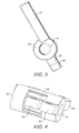
Figure 3 is a side view of the rocker arm arrangement ofFigure 2 ; and -
Figure 4 is a rear view of the rocker arm arrangement ofFigure 2 . -
Figure 1 illustrates avalve actuation arrangement 10 for an internal combustion engine (not shown) including arocker arm arrangement 30 as described in further detail below. Thevalve actuation arrangement 10 shown is in the form of avalve train 10 suitable for use in an overhead valve engine with a substantially square shaped valve configuration. Thevalve train 10 is depicted as a valve train for a four-cylinder, four-stroke, inline internal combustion engine, having four valves per cylinder. One skilled in the art will recognize, however, that valve trains comprising thevalve actuation 10 androcker arm 30 arrangements described below may be used in many other types of overhead valve engines with any number of cylinders in any configuration, for example an inline or V-configuration. - The
valve train 10 may include acamshaft 11 of a conventional design, havingcam lobes 12. In total, the depictedcamshaft 11 features eightcam lobes 12, two for each cylinder of the four-cylinder engine with whichvalve train 10 may be used.Lifters 13, such as hydraulic tappets, may abutcamshaft 11 wherecam lobes 12 are provided, so that a rotating motion of thecamshaft 11 results in periodic activation of thelifters 13. Eachlifter 13 may support a first end of anelongate push rod 18. A second end of thepush rod 18 may normally be in contact with afirst end rocker arm push rod 18 and thefirst end rocker arm push rod retainer 23. Therocker arms rocker shaft 39. - Actuation ends of a
rocker arm first ends valves valve valve stem 15 that may be slidably mounted within avalve stem guide 16. An upper end of eachvalve stem 15 may be connected to avalve spring 17 to bias thevalve - In an alternative valve train arrangement, camshaft 11 may be an overhead camshaft that acts on the upper surface of
rocker arm -
Figures 2 to 4 show therocker arm arrangement 30 used in thevalve actuation arrangement 10 ofFigure 1 . Therocker arm arrangement 30 may be disposed to actuate two inlet and twoexhaust valves valves rocker arms rocker arms common rocker shaft 39. The substantially square shape formed by thevalves longitudinal axis 40 ofrocker shaft 39 and two of its edges lie perpendicular tolongitudinal axis 40 ofrocker shaft 39. One set ofvalves valves 19 that are more closely disposed torocker shaft 39, and the other set ofvalves valves 20 that are more remotely disposed torocker shaft 39. Either one of the sets ofvalves - Each set of inlet/
exhaust valves 19 proximal to therocker shaft 39 may be actuated by afirst rocker arm 31. Thefirst rocker arm 31 may have a 'split' configuration, namely a generally forked, Y- or C-shaped configuration comprising a connectingbody 32, from which project two actuating levers 33, the ends of which each actuate one valve. The two actuating levers 33 may project in opposing directions from the connectingbody 32. A cylindrical bore (not shown) may be provided through thebody 32 to enable the pivotal mounting of thefirst rocker arm 31 on therocker shaft 39. - The
first rocker arm 31 may further comprise a single point ofadjustment 34, to enable the actuation of thelevers 33. The single point ofadjustment 34 may be in the form of aprotrusion 34 extending from thebody 32 in an opposing direction to that of the actuating levers 33. Theprotrusion 34 may have abore 42 through it to facilitate the actuation. The first rocker arm 31 pivots aboutrocker shaft 39, and may be driven by apushrod 18, which may in turn be driven by thecamshaft 11. - Each set of inlet/
exhaust valves 20 distal to therocker shaft 39 may be actuated by asecond rocker arm 35. Thesecond rocker arm 35 may also have a 'split' configuration, again being a generally forked, Y- or C-shaped configuration comprising a connectingbody 36, from which project two actuatinglevers 37, the ends of which each actuate one valve. The twoactuating levers 37 may project in opposing directions from the connectingbody 36. Acylindrical bore 41 through thebody 36 may enable the pivotal mounting of thesecond rocker arm 35 on therocker shaft 39. - The
second rocker arm 35 may further comprise a single point of adjustment, to enable the actuation of thelevers 37. The single point of adjustment may be in the form of aprotrusion 38 extending from thebody 36 in an opposing direction to that of the actuating levers 37. Theprotrusion 38 may have abore 43 through it to facilitate the actuation. - The
second rocker arm 35 also pivots aboutrocker shaft 39, and may be driven by apushrod 18, which may in turn be driven by thecamshaft 11. - The
first rocker arm 31 may be nested within thesecond rocker arm 35, such that the connectingbody 32 of thefirst rocker arm 31 is positioned within and is substantially surrounded by the connectingbody 36 of thesecond rocker arm 35. The tworocker arms second rocker arm 35 may be arcuate and may extend around the actuating levers 33 of thefirst rocker arm 31. This enables a substantially square valve arrangement to be achieved using tworocker arms common rocker shaft 39. - Alternatively, the actuating levers 37 of the
second rocker arm 35 may extend around the connectingbody 32 of thefirst rocker arm 31. The ends of the actuating levers 33 of thefirst rocker arm 31 may then protrude past the ends of the actuating levers 37 of thesecond rocker arm 35. - In an alternative embodiment for use with an engine having only three valves per cylinder,
first rocker arm 31 may be replaced by an individual rocker arm which may actuate a single inlet/exhaust valve. - In a further alternative embodiment, for use with an engine having only three valves per cylinder, or, in combination with the previous embodiment, for use with an engine having only two valves per cylinder,
second rocker arm 35 may be replaced by an individual rocker arm which may actuate a single inlet/exhaust valve. In this embodiment the actuating lever of thesecond rocker arm 35 may be arcuate and extend around the actuating lever, or at least one of the actuating levers, of thefirst rocker arm 31. - In a yet further alternative embodiment, the
second rocker arm 35 may be nested within thefirst rocker arm 31, such that the connectingbody 36 of thesecond rocker arm 35 is positioned within and is substantially surrounded by the connectingbody 32 of thefirst rocker arm 31. This embodiment may co-operate with any of the previous embodiments with respect to the number and the arrangement of the actuating levers. -
Rocker arms Shaft 39 may be made from steel, which may be heat treated. - The disclosure has industrial applicability in the manufacture and operation of valve trains for internal combustion engines.
- During normal operation of the
valve actuation arrangement 10 androcker arm arrangement 30 therefor, thecamshaft 11 with thecam lobes 12 may rotate, which in turn may cause thelifters 13 to move thepush rods 18 reciprocally upward and downward. As apush rod 18 moves upward, the first end of the associatedrocker arm rocker shaft 39. The pivoting motion of therocker arm rocker arm exhaust valves cam lobes 12, thepush rod 18 may then move downward as the upward force on thepush rod 18 is relieved and thusvalve spring 17 may force therocker arm valves
Claims (15)
- A rocker arm arrangement (30) for an internal combustion engine, comprising:a first rocker arm (31) comprising a first connecting body (32) and at least one first actuating lever (33) projecting from the first connecting body (32); anda second rocker arm (35) comprising a second connecting body (36) and at least one second actuating lever (37) projecting from the second connecting body (36); whereinthe first rocker arm (31) is pivotally mountable on a rocker shaft (39) ;the second rocker arm (35) is pivotally mountable on the same rocker shaft (39); andone of the first (31) or second (35) rocker arms is configured to be positioned within the other of the first (31) or second (35) rocker arms.
- A rocker arm arrangement (30) according to claim 1, wherein one of the first (31) or second (35) rocker arms is nestable within the other of the first (31) or second (35) rocker arms on the rocker shaft (39).
- A rocker arm arrangement (30) according to claim 1 or claim 2, wherein one of the first (31) or second (35) rocker arms is configured to be positioned within the other of the first (31) or second (35) rocker arms such that the first (32) or second (36) connecting body is positioned respectively within the second (36) or first (32) connecting body.
- A rocker arm arrangement (30) according to claim 3, wherein one of the first (32) or second (36) connecting bodies (32) is substantially surrounded by the other of the first (32) or second (36) connecting bodies.
- A rocker arm arrangement (30) according to any one of the preceding claims, further comprising:a first single point of adjustment to actuate the first rocker arm (31); anda second single point of adjustment to actuate the second rocker arm (35).
- A rocker arm arrangement (30) according to any one of the preceding claims, wherein the at least one actuating lever (37) of the second rocker arm (35) is arcuate and extends around the at least one actuating lever (33) of the first rocker arm (31).
- A rocker arm arrangement (30) according to any one of the preceding claims, wherein the first (31) and second (35) rocker arms extend away from the rocker shaft (39) in a substantially common direction.
- A rocker arm arrangement (30) according to any one of the preceding claims, wherein the first rocker arm (31) comprises two first actuating levers (33) and the second rocker arm (35) comprises two second actuating levers (37).
- A rocker arm arrangement (30) according to claim 8, wherein the ends of the two first actuating levers (33) and the ends of the two second actuating levers (37) comprise the four corners of a substantially square configuration.
- A valve actuation arrangement (30) according to claim 9, wherein the substantially square configuration formed by the ends of the two first actuating levers (33) and the ends of the two second actuating levers (37) is oriented such that two of its edges lie parallel to a longitudinal axis (40) of the rocker shaft (39) and two of its edges lie perpendicular to the longitudinal axis (40) of the rocker shaft (39).
- A valve actuation arrangement (10) for an internal combustion engine, comprising:a rocker arm arrangement (30) according to any one of the preceding claims;at least one inlet valve actuable by one of the first (31) or second (35) rocker arms; andat least one exhaust valve actuable by the other of the first (31) or second (35) rocker arms.
- A valve actuation arrangement (10) according to claim 11, wherein the rocker arm arrangement (30) is pivotally mounted on a rocker shaft (39).
- A valve actuation arrangement (10) according to claim 12, wherein:the at least one inlet or exhaust valve is proximal to the rocker shaft (39) and configured for actuation by the first rocker arm (31) ; andthe other valve type is distal to the rocker shaft (39) and configured for actuation by the second rocker arm (35).
- A valve actuation arrangement (10) according to any one of claims 11 to 13, wherein the first rocker arm (31) comprises two first actuating levers (33) and the second rocker arm (35) comprises two second actuating levers (37), and wherein the four valves comprise the four corners of a substantially square configuration.
- A valve actuation arrangement (10) according to claim 14, wherein the substantially square configuration formed by the valves (19,20) is oriented such that two of its edges lie parallel to a longitudinal axis (40) of the rocker shaft (39) and two of its edges lie perpendicular to the longitudinal axis (40) of the rocker shaft (39).
Priority Applications (2)
| Application Number | Priority Date | Filing Date | Title |
|---|---|---|---|
| EP10252145A EP2466080A1 (en) | 2010-12-17 | 2010-12-17 | Valve actuation and rocker arm arrangement |
| PCT/GB2011/052513 WO2012080756A1 (en) | 2010-12-17 | 2011-12-19 | Valve actuation and rocker arm arrangment |
Applications Claiming Priority (1)
| Application Number | Priority Date | Filing Date | Title |
|---|---|---|---|
| EP10252145A EP2466080A1 (en) | 2010-12-17 | 2010-12-17 | Valve actuation and rocker arm arrangement |
Publications (1)
| Publication Number | Publication Date |
|---|---|
| EP2466080A1 true EP2466080A1 (en) | 2012-06-20 |
Family
ID=43877179
Family Applications (1)
| Application Number | Title | Priority Date | Filing Date |
|---|---|---|---|
| EP10252145A Withdrawn EP2466080A1 (en) | 2010-12-17 | 2010-12-17 | Valve actuation and rocker arm arrangement |
Country Status (2)
| Country | Link |
|---|---|
| EP (1) | EP2466080A1 (en) |
| WO (1) | WO2012080756A1 (en) |
Families Citing this family (1)
| Publication number | Priority date | Publication date | Assignee | Title |
|---|---|---|---|---|
| CN107939467B (en) * | 2017-12-28 | 2023-12-15 | 潍柴动力股份有限公司 | Valve intake and exhaust rocker arm structure and diesel engine |
Citations (3)
| Publication number | Priority date | Publication date | Assignee | Title |
|---|---|---|---|---|
| DE2025305A1 (en) * | 1970-05-23 | 1971-12-09 | Daimler-Benz Ag, 7000 Stuttgart | Valve control |
| DE4214800A1 (en) * | 1992-05-04 | 1993-11-11 | Kloeckner Humboldt Deutz Ag | Four-stroke cycle IC engine - has cylinder head contg. two inlet valves and two exhaust valves arranged in plane parallel to camshaft and operated by rocker levers |
| WO2010057648A1 (en) | 2008-11-24 | 2010-05-27 | Perkins Engines Company Limited | Push rod retainer, rocker arm and method for retaining together a push rod and a rocker arm |
-
2010
- 2010-12-17 EP EP10252145A patent/EP2466080A1/en not_active Withdrawn
-
2011
- 2011-12-19 WO PCT/GB2011/052513 patent/WO2012080756A1/en not_active Ceased
Patent Citations (3)
| Publication number | Priority date | Publication date | Assignee | Title |
|---|---|---|---|---|
| DE2025305A1 (en) * | 1970-05-23 | 1971-12-09 | Daimler-Benz Ag, 7000 Stuttgart | Valve control |
| DE4214800A1 (en) * | 1992-05-04 | 1993-11-11 | Kloeckner Humboldt Deutz Ag | Four-stroke cycle IC engine - has cylinder head contg. two inlet valves and two exhaust valves arranged in plane parallel to camshaft and operated by rocker levers |
| WO2010057648A1 (en) | 2008-11-24 | 2010-05-27 | Perkins Engines Company Limited | Push rod retainer, rocker arm and method for retaining together a push rod and a rocker arm |
Also Published As
| Publication number | Publication date |
|---|---|
| WO2012080756A1 (en) | 2012-06-21 |
Similar Documents
| Publication | Publication Date | Title |
|---|---|---|
| EP2715076B1 (en) | Primary and auxiliary rocker arm assembly for engine valve actuation | |
| US10683778B2 (en) | Removable valve bridges and valve actuation systems including the same | |
| GB2447111A (en) | Internal combustion engine with valve deactivation | |
| EP1793098A3 (en) | System for variable valvetrain actuation | |
| CN101122246A (en) | Internal combustion engine with variable valve gear | |
| EP0601570A1 (en) | Valve gear for internal combustion engine | |
| CN100460631C (en) | Variable valve gear for internal combustion engines | |
| CA2555638A1 (en) | Lift-variable valve-operating system for internal combustion engine | |
| EP2466080A1 (en) | Valve actuation and rocker arm arrangement | |
| EP0967367A3 (en) | Valve drive system for an internal combustion engine | |
| US6481398B2 (en) | High-low speed range switching type valve mechanism for internal combustion engine | |
| US4773360A (en) | Internal combustion engine | |
| GB2421765A (en) | Valve operating mechanism with two cams | |
| EP1697619B1 (en) | Variable valve gear | |
| JP2011052546A (en) | Variable valve train | |
| US8794204B2 (en) | Valvetrain for overhead valve engine | |
| US7318399B2 (en) | Variable valve mechanism | |
| CN114320516A (en) | Engine valve system having rocker arm assembly with roller lock for selectively deactivating engine valves | |
| AU1238092A (en) | Valve actuation device | |
| JP4195463B2 (en) | Variable valve operating device for internal combustion engine | |
| HUP0202368A2 (en) | Device for valve stroke adjustment of an internal combustion piston engine | |
| EP1270882A3 (en) | Four-stroke internal combustion engine with valve resting mechanism | |
| JPWO2025027725A5 (en) | ||
| JPH0221527Y2 (en) | ||
| JPS633368Y2 (en) |
Legal Events
| Date | Code | Title | Description |
|---|---|---|---|
| PUAI | Public reference made under article 153(3) epc to a published international application that has entered the european phase |
Free format text: ORIGINAL CODE: 0009012 |
|
| AK | Designated contracting states |
Kind code of ref document: A1 Designated state(s): AL AT BE BG CH CY CZ DE DK EE ES FI FR GB GR HR HU IE IS IT LI LT LU LV MC MK MT NL NO PL PT RO RS SE SI SK SM TR |
|
| AX | Request for extension of the european patent |
Extension state: BA ME |
|
| STAA | Information on the status of an ep patent application or granted ep patent |
Free format text: STATUS: THE APPLICATION IS DEEMED TO BE WITHDRAWN |
|
| 18D | Application deemed to be withdrawn |
Effective date: 20121221 |