EP2465769A2 - Optimization of structures subjected to hot gas streams - Google Patents
Optimization of structures subjected to hot gas streams Download PDFInfo
- Publication number
- EP2465769A2 EP2465769A2 EP11194128A EP11194128A EP2465769A2 EP 2465769 A2 EP2465769 A2 EP 2465769A2 EP 11194128 A EP11194128 A EP 11194128A EP 11194128 A EP11194128 A EP 11194128A EP 2465769 A2 EP2465769 A2 EP 2465769A2
- Authority
- EP
- European Patent Office
- Prior art keywords
- fairing
- front part
- aircraft
- rear part
- erosion
- Prior art date
- Legal status (The legal status is an assumption and is not a legal conclusion. Google has not performed a legal analysis and makes no representation as to the accuracy of the status listed.)
- Withdrawn
Links
- 238000005457 optimization Methods 0.000 title 1
- 239000003381 stabilizer Substances 0.000 claims abstract description 26
- 239000000463 material Substances 0.000 claims abstract description 9
- 239000004918 carbon fiber reinforced polymer Substances 0.000 claims description 4
- 239000002184 metal Substances 0.000 claims description 4
- 229910001220 stainless steel Inorganic materials 0.000 claims description 4
- 239000010935 stainless steel Substances 0.000 claims description 4
- 239000002131 composite material Substances 0.000 claims description 3
- 229920002430 Fibre-reinforced plastic Polymers 0.000 claims description 2
- 239000011151 fibre-reinforced plastic Substances 0.000 claims description 2
- 239000011521 glass Substances 0.000 claims description 2
- 238000001465 metallisation Methods 0.000 claims description 2
- 239000002071 nanotube Substances 0.000 claims 1
- 230000003628 erosive effect Effects 0.000 description 25
- 238000013461 design Methods 0.000 description 10
- 230000004224 protection Effects 0.000 description 9
- 230000015556 catabolic process Effects 0.000 description 3
- 238000006731 degradation reaction Methods 0.000 description 3
- 230000000694 effects Effects 0.000 description 3
- 238000009924 canning Methods 0.000 description 2
- 238000009499 grossing Methods 0.000 description 2
- 238000007689 inspection Methods 0.000 description 2
- 238000004519 manufacturing process Methods 0.000 description 2
- 239000007769 metal material Substances 0.000 description 2
- 238000000034 method Methods 0.000 description 2
- 238000003466 welding Methods 0.000 description 2
- 229910000831 Steel Inorganic materials 0.000 description 1
- 238000005260 corrosion Methods 0.000 description 1
- 230000007797 corrosion Effects 0.000 description 1
- 230000000593 degrading effect Effects 0.000 description 1
- 239000007789 gas Substances 0.000 description 1
- 238000005304 joining Methods 0.000 description 1
- 238000012423 maintenance Methods 0.000 description 1
- 238000012986 modification Methods 0.000 description 1
- 230000004048 modification Effects 0.000 description 1
- 239000002105 nanoparticle Substances 0.000 description 1
- 238000010422 painting Methods 0.000 description 1
- 238000003908 quality control method Methods 0.000 description 1
- 238000007493 shaping process Methods 0.000 description 1
- 239000010959 steel Substances 0.000 description 1
- 238000011282 treatment Methods 0.000 description 1
Images


Classifications
-
- B—PERFORMING OPERATIONS; TRANSPORTING
- B64—AIRCRAFT; AVIATION; COSMONAUTICS
- B64C—AEROPLANES; HELICOPTERS
- B64C5/00—Stabilising surfaces
- B64C5/02—Tailplanes
-
- B—PERFORMING OPERATIONS; TRANSPORTING
- B64—AIRCRAFT; AVIATION; COSMONAUTICS
- B64C—AEROPLANES; HELICOPTERS
- B64C7/00—Structures or fairings not otherwise provided for
Definitions
- the present invention refers to the optimisation of structures that are subjected to hot streams from gases, in particular, to an aircraft fairing design and, more in particular, to the fairing design of the horizontal stabilizer of an aircraft.
- An aircraft fairing is a structure whose primary function is to produce a smooth outline and reduce drag. These structures are covers for gaps and spaces between parts of an aircraft, thus reducing drag and interference drag in these parts, also improving the aircraft appearance.
- fairings are commonly used on elevator and horizontal stabilizer tips, on engine cowlings, on fin and rudder tips, and on wing root and wing tips. Particularly in the case of fairings on elevator and horizontal stabilizer tips, the fairing has the objective of smoothing out the airflow at the tips.
- Fairings on aircraft horizontal stabilizers suffer from erosion degrading them after time, as the rest of fairings present in the aircraft, as they are elements working in particularly erosive environments.
- these fairings also suffer from erosion coming from the hot air stream from the engines (higher temperature and speed conditions), the erosion issue therefore being a main issue in the design of these horizontal stabilizers fairings, specially in cases of small aircraft, with a short distance between the wing and the tail. This effect coming from the hot air stream from the engines is particularly relevant in the cases of aircraft landing and take-off.
- these fairings are not made as light and cheap as they could because of the erosion requirements limitation, therefore being provided with specific anti-erosion protection.
- fairings for horizontal stabilizers are manufactured from a metallic material, additionally comprising erosion protection areas to avoid the base element being deteriorated.
- fairings Due to the special configuration and twisting shape of fairings in horizontal stabilizers, these fairings are made at present mainly from metallic sheets being shaped and joined afterwards, by welding or by rivets.
- These known fairings have the problem of requiring costly and time consuming inspection requirements, such as x-ray, also having higher manufacturings costs, because of the manual processes employed.
- these elements present quality problems because of their particular shaping, typically known as oil canning.
- oil canning it is meant a moderate deformation or buckling of the flat sheet material made of metal, typically caused by uneven stresses at fastening points.
- the present invention is oriented towards this need.
- An object of the present invention is to provide an optimised aircraft fairing design, in particular, an optimised fairing design for the horizontal stabilizer of an aircraft.
- the fairing comprises a front part and a rear part, the front part being arranged such that it covers a limited extent of the fairing, which is the part of the fairing receiving hot air stream coming from the engines.
- the front part in the fairing is manufactured for resisting erosion degradation, whereas the rear part of the fairing has the requirements of providing the dimensional configuration of the fairing, this rear part being made of a single unitary piece.
- the front and rear parts of the fairing according to the invention are overlapped and further joined by using rivets. For this reason, the rear part over which the front part overlaps is enlarged so that the front part is supported on it. The stronger requirements are then to be taken in the design and structure of the front part, which is the part of the fairing resisting erosion.
- fairings 1 are commonly used on elevator and horizontal stabilizer tips, on engine cowlings, on fin and rudder tips, and on wing root and wing tips. Particularly in the case of fairings on elevator and horizontal stabilizer tips, the fairing has the objective of smoothing out the airflow at the tips.
- fairings 10 on aircraft horizontal stabilizers 3 particularly suffer from erosion as they also also withstand a hot air stream 6 coming from the engines 4, which is particularly relevant for the cases in which there exists a short distance 5 between the wing 1 and the tail 7, as it is shown in Figure 2 (where it has been shaded the area of the horizontal stabilizer 3 wich can suffer from erosion coming from the hot air stream 6 from the aircraft engines 4).
- the distance 5 between the wing and the tail 7 is considered short when it is of 20 metres or less, which happens for short haul aircraft having medium capacity of around 150 passengers.
- This effect of the hot air stream 6 from the engines 4 is particularly relevant in the cases of aircraft landing and take-off (see Figure 1 for the case of take-off).
- an aircraft fairing 10 is proposed, particularly for the horizontal stabilizer 3 of an aircraft, such that this fairing 10 is basically an aerodynamic cover of the tip part of the horizontal stabilizer 3 of the aircraft.
- the fairing 10 of the invention comprises a front part 11 and a rear part 12: the front part 11 is mainly suffering from erosion coming from the hot air stream 6 from the engines 4, whereas the rear part 12 is designed by aerodynamic loads only. Therefore, the front part 11 is arranged such that it covers a limited extent of the fairing 10, which is the part of the fairing 10 receiving hot air stream coming from the aircraft engines 4, which is typically of 10% or less of the total overall length of the fairing 10; the rear part 12 covers the rest of the surface of the fairing 10.
- the front part 11 in the fairing 10 is manufactured for resisting erosion degradation, whereas the rear part 12 of the fairing 10 has the requirements of providing the dimensional configuration of the cited fairing 10, this rear part 12 being made of a single unitary piece.
- This rear part 12 is made of a single piece makes interchangeability possible, which is certainly advantageous for maintenance and repairing needs.
- the front and rear parts of the fairing 10 according to the invention are overlapped and further joined preferably by rivets. For this reason, the rear part 12 over which the front part 11 overlaps is enlarged so that the front part 11 is supported on it. Highest requirements are then to be taken in the design and structure of the front part 11, which is the part of the fairing 10 resisting erosion.
- the front part 11 of the fairing 10 is preferably manufactured using an anti-erosion material, this fort part 11 being assembled or joined to the rear part 12 which is the main structure of the fairing 10, this rear part 12 being enlarged in order to support the front part 11.
- This front part 11 may be heavier than the traditional parts in known fairings, but it has a better behaviour against erosion.
- the rear part 12, which is also the main and bigger part of the fairing 10 is made from a material completely different to that of the front part 11, as this rear part 12 is not affected by erosion, so a slimmer, lighter and cheaper part is designed and manufactured.
- the front part 11 is made of a metallic material, preferably steel.
- the front part 11 comprises a metallization in its external surface.
- the front part 11 can comprise nanoparticles.
- the horizontal surface with respect to the aircraft flight direction of the horizontal stabilizer 3 is affected by the hot air stream 6 coming from the engines 4, causing an increased erosion effect on the tail 7 surfaces.
- the front 11 part and the rear part 12 of the fairing 10 can be separated, as shown in Figures 4a and 4b : some structural elements in the primary structure of the horizontal stabilizer 3, such as ribs, could be enlarged in order to support the front part 11 of the fairing 10 specifically suffering from erosion and protected against it.
- these enlarged elements are ribs, marked as 20 and 22.
- the front part 11 of the fairing 10 which is the one designed for resisting erosion, is made of stainless steel having a very low thickness supported by the rear part 12 made of composite material, preferably of CFRP (carbon fiber-reinforced polymer) or GFRP (glass fiber-reinforced polymer).
- CFRP carbon fiber-reinforced polymer
- GFRP glass fiber-reinforced polymer
- the front part 11 of the fairing 10 is made of stainless steel having a thickness of about 0,4 mm, which has proved to be satisfactory, as this front part 11 is designed only for erosion resistance; however, an additional support element or a thickness increase in this front part 11 can be made necessary for aerodynamic loads design or for joining needs, for example.
Landscapes
- Engineering & Computer Science (AREA)
- Aviation & Aerospace Engineering (AREA)
- Laminated Bodies (AREA)
- Pressure Welding/Diffusion-Bonding (AREA)
Abstract
Description
- The present invention refers to the optimisation of structures that are subjected to hot streams from gases, in particular, to an aircraft fairing design and, more in particular, to the fairing design of the horizontal stabilizer of an aircraft.
- An aircraft fairing is a structure whose primary function is to produce a smooth outline and reduce drag. These structures are covers for gaps and spaces between parts of an aircraft, thus reducing drag and interference drag in these parts, also improving the aircraft appearance.
- On aircraft, fairings are commonly used on elevator and horizontal stabilizer tips, on engine cowlings, on fin and rudder tips, and on wing root and wing tips. Particularly in the case of fairings on elevator and horizontal stabilizer tips, the fairing has the objective of smoothing out the airflow at the tips.
- Fairings on aircraft horizontal stabilizers suffer from erosion degrading them after time, as the rest of fairings present in the aircraft, as they are elements working in particularly erosive environments. However, these fairings also suffer from erosion coming from the hot air stream from the engines (higher temperature and speed conditions), the erosion issue therefore being a main issue in the design of these horizontal stabilizers fairings, specially in cases of small aircraft, with a short distance between the wing and the tail. This effect coming from the hot air stream from the engines is particularly relevant in the cases of aircraft landing and take-off. Thus, these fairings are not made as light and cheap as they could because of the erosion requirements limitation, therefore being provided with specific anti-erosion protection. A further consideration to be taken into account is the complicated and twisting surface of these fairings. All the above-mentioned considerations and requirements force the manufacturing of fairings for horizontal stabilizers as full parts in a non-optimal way, in order to resist erosion degradation.
- For the reasons mentioned, fairings for horizontal stabilizers are manufactured from a metallic material, additionally comprising erosion protection areas to avoid the base element being deteriorated.
- Due to the special configuration and twisting shape of fairings in horizontal stabilizers, these fairings are made at present mainly from metallic sheets being shaped and joined afterwards, by welding or by rivets. These known fairings have the problem of requiring costly and time consuming inspection requirements, such as x-ray, also having higher manufacturings costs, because of the manual processes employed. Besides, these elements present quality problems because of their particular shaping, typically known as oil canning. By oil canning, it is meant a moderate deformation or buckling of the flat sheet material made of metal, typically caused by uneven stresses at fastening points. Furthermore, it is becoming more difficult to find appropriate surface protection treatments in these elements, taking into account that special surface protection against erosion is mandatory in such kind of elements.
- Known solutions are focused at present in the use of metal fairings: because of the big dimensions of these elements and the related weight considerations, the most commonly used metal is alluminium (though a fairing made in composite material would anyhow be lighter). However, alluminium material would not resist long or mid-term erosion from the hot air stream coming from the engines. Furthermore, once a metallic sheet has been shaped and joined, a further protection against corrosion has to be added, together with a specific erosion protection, such as painting. This has the problem of not assuring a permanent protection of the element, as some parts of this element can be damaged or not properly covered with such protections. In some case, stainless steel is used as a further cover protecting the fairing: in such cases, this protection is bonded or cocured over the fairing, which limitates both the thickness of the material and the process used.
- It would thus be desirable to provide an optimised fairing for the horizontal stabilizer of an aircraft, overcoming the above-mentioned drawbacks.
- The present invention is oriented towards this need.
- An object of the present invention is to provide an optimised aircraft fairing design, in particular, an optimised fairing design for the horizontal stabilizer of an aircraft.
- According to the invention, the fairing comprises a front part and a rear part, the front part being arranged such that it covers a limited extent of the fairing, which is the part of the fairing receiving hot air stream coming from the engines. The front part in the fairing is manufactured for resisting erosion degradation, whereas the rear part of the fairing has the requirements of providing the dimensional configuration of the fairing, this rear part being made of a single unitary piece.
- The front and rear parts of the fairing according to the invention are overlapped and further joined by using rivets. For this reason, the rear part over which the front part overlaps is enlarged so that the front part is supported on it. The stronger requirements are then to be taken in the design and structure of the front part, which is the part of the fairing resisting erosion.
- Other characteristics and advantages of the present invention will be clear from the following detailed description of embodiments illustrative of its object in relation to the attached figures.
-
-
Figure 1 shows a general view of the take-off of an aircraft, showing the area of the aircraft horizontal stabilizer suffering from heat stream coming from the engines. -
Figure 2 shows a plan view of an aircraft in flight, further showing the areas of the horizontal stabilizer that are subjected to hot stream coming from the engines. -
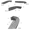
Figures 3a, 3b and 3c show different views of the structure of the fairing of an aircraft horizontal stabilizer according to the present invention. -
Figures 4a and4b show further details and views of the fairing design structure according to the present invention. - On aircraft, fairings 1 are commonly used on elevator and horizontal stabilizer tips, on engine cowlings, on fin and rudder tips, and on wing root and wing tips. Particularly in the case of fairings on elevator and horizontal stabilizer tips, the fairing has the objective of smoothing out the airflow at the tips.
- As it is shown in
Figures 1 and 2 ,fairings 10 on aircrafthorizontal stabilizers 3 particularly suffer from erosion as they also also withstand ahot air stream 6 coming from theengines 4, which is particularly relevant for the cases in which there exists ashort distance 5 between the wing 1 and thetail 7, as it is shown inFigure 2 (where it has been shaded the area of thehorizontal stabilizer 3 wich can suffer from erosion coming from thehot air stream 6 from the aircraft engines 4). As a reference, thedistance 5 between the wing and thetail 7 is considered short when it is of 20 metres or less, which happens for short haul aircraft having medium capacity of around 150 passengers. This effect of thehot air stream 6 from theengines 4 is particularly relevant in the cases of aircraft landing and take-off (seeFigure 1 for the case of take-off). - According to the invention, an
aircraft fairing 10 is proposed, particularly for thehorizontal stabilizer 3 of an aircraft, such that thisfairing 10 is basically an aerodynamic cover of the tip part of thehorizontal stabilizer 3 of the aircraft. Thefairing 10 of the invention comprises afront part 11 and a rear part 12: thefront part 11 is mainly suffering from erosion coming from thehot air stream 6 from theengines 4, whereas therear part 12 is designed by aerodynamic loads only. Therefore, thefront part 11 is arranged such that it covers a limited extent of thefairing 10, which is the part of the fairing 10 receiving hot air stream coming from theaircraft engines 4, which is typically of 10% or less of the total overall length of thefairing 10; therear part 12 covers the rest of the surface of thefairing 10. Thefront part 11 in thefairing 10 is manufactured for resisting erosion degradation, whereas therear part 12 of thefairing 10 has the requirements of providing the dimensional configuration of the citedfairing 10, thisrear part 12 being made of a single unitary piece. The fact that thisrear part 12 is made of a single piece makes interchangeability possible, which is certainly advantageous for maintenance and repairing needs. - The front and rear parts of the
fairing 10 according to the invention are overlapped and further joined preferably by rivets. For this reason, therear part 12 over which thefront part 11 overlaps is enlarged so that thefront part 11 is supported on it. Highest requirements are then to be taken in the design and structure of thefront part 11, which is the part of the fairing 10 resisting erosion. - The
front part 11 of thefairing 10 is preferably manufactured using an anti-erosion material, thisfort part 11 being assembled or joined to therear part 12 which is the main structure of thefairing 10, thisrear part 12 being enlarged in order to support thefront part 11. Thisfront part 11 may be heavier than the traditional parts in known fairings, but it has a better behaviour against erosion. However, taking into consideration what has been previously cited, therear part 12, which is also the main and bigger part of thefairing 10 is made from a material completely different to that of thefront part 11, as thisrear part 12 is not affected by erosion, so a slimmer, lighter and cheaper part is designed and manufactured. - Preferably, the
front part 11 is made of a metallic material, preferably steel. According to another embodiment of the invention, thefront part 11 comprises a metallization in its external surface. Also, thefront part 11 can comprise nanoparticles. - In the particular case in which the
distance 5 from the aircraft wing 1 to theaircraft tail 7 is short (as cited before, typically of less than 20 metres), the horizontal surface with respect to the aircraft flight direction of thehorizontal stabilizer 3 is affected by thehot air stream 6 coming from theengines 4, causing an increased erosion effect on thetail 7 surfaces. - According to the invention, the
front 11 part and therear part 12 of thefairing 10 can be separated, as shown inFigures 4a and4b : some structural elements in the primary structure of thehorizontal stabilizer 3, such as ribs, could be enlarged in order to support thefront part 11 of thefairing 10 specifically suffering from erosion and protected against it. InFigures 4a and4b , these enlarged elements are ribs, marked as 20 and 22. With this configuration, thefront part 11 of thefairing 10 transfers loads to the structure of thehorizontal stabilizer 3, such that thisfront part 11 is then designed following only erosion requirements (erosion from the hot air stream of the engines 4), so it can be made lighter and be optimised; therefore, thewhole fairing 10 design is optimised, according to the present invention. - According to a preferred embodiment of the invention, the
front part 11 of thefairing 10, which is the one designed for resisting erosion, is made of stainless steel having a very low thickness supported by therear part 12 made of composite material, preferably of CFRP (carbon fiber-reinforced polymer) or GFRP (glass fiber-reinforced polymer). Therear part 12 is made in one single piece, of one shoot. Thus, in this case, welding and special inspection requirements are avoided. This structure of therear part 12 is lighter and cheaper than the traditional ones, as in the traditional one quality control is an issue and lots of man hours are necessary for effecting an assembly of all parts together. Typically, thefront part 11 of the fairing 10 is made of stainless steel having a thickness of about 0,4 mm, which has proved to be satisfactory, as thisfront part 11 is designed only for erosion resistance; however, an additional support element or a thickness increase in thisfront part 11 can be made necessary for aerodynamic loads design or for joining needs, for example. - Although the present invention has been fully described in connection with preferred embodiments, it is evident that modifications may be introduced within the scope thereof, not considering this as limited by these embodiments, but by the contents of the following claims.
Claims (13)
- Fairing (10) for aircraft horizontal stabilizer (3) comprising a front part (11) and a rear part (12), the front part (11) covering a limited extent of the fairing (10) surface, which is the part of the fairing (10) receiving hot air stream (6) coming from the aircraft engines (4), this front part (11) being made of an anti-erosion material, the rear part (12) covering the rest of the surface of the fairing (10), this rear part (12) being made of a material resisting the aerodynamic loads existing on the fairing (10).
- Fairing (10) according to claim 1, wherein the front part (11) covers a 10% or less than the total overall length of the fairing (10).
- Fairing (10) according to any of claims 1-2, wherein the rear part (12) is a single unitary piece enlarged in order to allow the front part (11) overlapping over said part (12).
- Fairing (10) according to claim 3, wherein the front part (11) and the rear part (12) are further joined by rivets.
- Fairing (10) according to any of the previous claims, wherein the front part (11) is made of metal.
- Fairing (10) according to any of claims 1-4, wherein the front part (11) comprises an external metallisation.
- Fairing (10) according to any of claims 1-4, wherein the front part (11) comprises nanotubes.
- Fairing (10) according to claim 5, wherein the front part (11) is made of stainless steel, with a thickness of about 0,4 mm.
- Fairing (10) according to any of the previous claims, wherein the rear part (12) is made of composite material.
- Fairing (10) according to claim 9, wherein the rear part (12) is made of CFRP (carbon fiber-reinforced polymer).
- Fairing (10) according to claim 9, wherein the rear part (12) is made of GFRP (glass fiber-reinforced polymer).
- Aircraft comprising a horizontal stabilizer (3) with a fairing (10) according to any of claims 1-11.
- Aircraft according to claim 12, wherein the distance between the wing (1) and the tail (7) is less than 20 metres.
Applications Claiming Priority (1)
| Application Number | Priority Date | Filing Date | Title |
|---|---|---|---|
| ES201031879A ES2403361B1 (en) | 2010-12-17 | 2010-12-17 | OPTIMIZATION OF STRUCTURES SUBMITTED TO HOT GAS CURRENTS. |
Publications (2)
| Publication Number | Publication Date |
|---|---|
| EP2465769A2 true EP2465769A2 (en) | 2012-06-20 |
| EP2465769A3 EP2465769A3 (en) | 2014-01-08 |
Family
ID=45349414
Family Applications (1)
| Application Number | Title | Priority Date | Filing Date |
|---|---|---|---|
| EP11194128.2A Withdrawn EP2465769A3 (en) | 2010-12-17 | 2011-12-16 | Optimization of structures subjected to hot gas streams |
Country Status (5)
| Country | Link |
|---|---|
| US (1) | US8550398B2 (en) |
| EP (1) | EP2465769A3 (en) |
| CA (1) | CA2764340C (en) |
| ES (1) | ES2403361B1 (en) |
| RU (1) | RU2598492C2 (en) |
Families Citing this family (2)
| Publication number | Priority date | Publication date | Assignee | Title |
|---|---|---|---|---|
| US9586699B1 (en) | 1999-08-16 | 2017-03-07 | Smart Drilling And Completion, Inc. | Methods and apparatus for monitoring and fixing holes in composite aircraft |
| US9625361B1 (en) | 2001-08-19 | 2017-04-18 | Smart Drilling And Completion, Inc. | Methods and apparatus to prevent failures of fiber-reinforced composite materials under compressive stresses caused by fluids and gases invading microfractures in the materials |
Citations (2)
| Publication number | Priority date | Publication date | Assignee | Title |
|---|---|---|---|---|
| WO1996020108A1 (en) * | 1994-12-23 | 1996-07-04 | United Technologies Corporation | Engineered ceramic components for the leading edge of a helicopter rotor blade |
| GB2461133A (en) * | 2008-06-27 | 2009-12-30 | George Valentino Constantinou | Erosion-protecting devices for aircraft |
Family Cites Families (12)
| Publication number | Priority date | Publication date | Assignee | Title |
|---|---|---|---|---|
| US2567124A (en) * | 1946-05-10 | 1951-09-04 | Curtiss Wright Corp | Airfoil construction |
| US3712566A (en) * | 1971-02-25 | 1973-01-23 | Us Navy | Supersonic vehicle control surface having a thermally protective coating |
| FR2616409B1 (en) * | 1987-06-09 | 1989-09-15 | Aerospatiale | BLADE OF COMPOSITE MATERIALS AND MANUFACTURING METHOD THEREOF |
| US6341747B1 (en) * | 1999-10-28 | 2002-01-29 | United Technologies Corporation | Nanocomposite layered airfoil |
| DE10005348B4 (en) * | 2000-02-08 | 2004-05-06 | Airbus Deutschland Gmbh | Process for the manufacture of nose structures for aerodynamic surfaces |
| ES2197727B1 (en) * | 2000-07-27 | 2005-04-01 | Construcciones Aeronauticas, S.A. | AIRCRAFT SUSTAINING SURFACE ATTACK EDGE. |
| US8276847B2 (en) * | 2004-04-16 | 2012-10-02 | Airbus Operations Gmbh | Cover for an aircraft structure |
| US7334759B2 (en) * | 2004-12-18 | 2008-02-26 | Castillo Francisco J | Airplane surface protection film kits |
| GB0525896D0 (en) * | 2005-12-20 | 2006-02-01 | Airbus Uk Ltd | A joint for use in aircraft construction |
| DE102006052303B4 (en) * | 2006-11-03 | 2012-07-12 | Eads Deutschland Gmbh | Protection of aerospace structures exposed to erosion by nanoparticle-reinforced inorganic-organic hybrid coatings |
| FI20080208L (en) * | 2008-03-13 | 2008-03-27 | Patria Aerostructures Oy | Aircraft leading edge element, method of making the same, and wing and stabilizer |
| WO2011087411A1 (en) * | 2010-01-14 | 2011-07-21 | Saab Ab | An aerodynamic surface with improved properties |
-
2010
- 2010-12-17 ES ES201031879A patent/ES2403361B1/en not_active Expired - Fee Related
-
2011
- 2011-04-21 US US13/091,202 patent/US8550398B2/en not_active Expired - Fee Related
- 2011-12-16 EP EP11194128.2A patent/EP2465769A3/en not_active Withdrawn
- 2011-12-16 RU RU2011151537/11A patent/RU2598492C2/en not_active IP Right Cessation
- 2011-12-19 CA CA2764340A patent/CA2764340C/en not_active Expired - Fee Related
Patent Citations (2)
| Publication number | Priority date | Publication date | Assignee | Title |
|---|---|---|---|---|
| WO1996020108A1 (en) * | 1994-12-23 | 1996-07-04 | United Technologies Corporation | Engineered ceramic components for the leading edge of a helicopter rotor blade |
| GB2461133A (en) * | 2008-06-27 | 2009-12-30 | George Valentino Constantinou | Erosion-protecting devices for aircraft |
Also Published As
| Publication number | Publication date |
|---|---|
| CA2764340A1 (en) | 2012-06-17 |
| US8550398B2 (en) | 2013-10-08 |
| US20120153083A1 (en) | 2012-06-21 |
| RU2598492C2 (en) | 2016-09-27 |
| CA2764340C (en) | 2018-04-17 |
| ES2403361A1 (en) | 2013-05-17 |
| EP2465769A3 (en) | 2014-01-08 |
| ES2403361B1 (en) | 2014-04-29 |
| RU2011151537A (en) | 2013-06-27 |
Similar Documents
| Publication | Publication Date | Title |
|---|---|---|
| EP2041399B1 (en) | Aircraft engine inlet having zone of deformation | |
| CN104066647B (en) | Aircraft fuselage section with improved impact resistance and damage tolerance | |
| US8371537B2 (en) | Aircraft structure with hinge rib assembly | |
| US10093406B2 (en) | Aircraft frame for tailstrike angle enhancement | |
| EP4140877B1 (en) | Slat for an aircraft wing, method for manufacturing such a slat | |
| CN112407244B (en) | Aircraft leading edge assembly | |
| EP3135578B1 (en) | Leading-edge structure for aircraft, wing for aircraft, and aircraft | |
| EP3243744B1 (en) | Aircraft joint | |
| US11591098B2 (en) | Nacelle forward part of a propulsion assembly comprising an inclined stiffening frame | |
| EP2886449A1 (en) | Leading edge for an aircraft lifting surface | |
| US11427298B2 (en) | Advanced plume suppressing segmented heat shield | |
| US10450081B2 (en) | Aircraft engine pylon to wing mounting assembly | |
| US9868539B2 (en) | Aircraft engine pylon to wing mounting assembly | |
| CA2764340C (en) | Optimization of structures subjected to hot gas streams | |
| US9688412B2 (en) | Aerodynamic fairing | |
| US10370113B2 (en) | Flow drag mitigation device | |
| EP4378824A1 (en) | Flow body for an aircraft with split ribs |
Legal Events
| Date | Code | Title | Description |
|---|---|---|---|
| PUAI | Public reference made under article 153(3) epc to a published international application that has entered the european phase |
Free format text: ORIGINAL CODE: 0009012 |
|
| AK | Designated contracting states |
Kind code of ref document: A2 Designated state(s): AL AT BE BG CH CY CZ DE DK EE ES FI FR GB GR HR HU IE IS IT LI LT LU LV MC MK MT NL NO PL PT RO RS SE SI SK SM TR |
|
| AX | Request for extension of the european patent |
Extension state: BA ME |
|
| PUAL | Search report despatched |
Free format text: ORIGINAL CODE: 0009013 |
|
| AK | Designated contracting states |
Kind code of ref document: A3 Designated state(s): AL AT BE BG CH CY CZ DE DK EE ES FI FR GB GR HR HU IE IS IT LI LT LU LV MC MK MT NL NO PL PT RO RS SE SI SK SM TR |
|
| AX | Request for extension of the european patent |
Extension state: BA ME |
|
| RIC1 | Information provided on ipc code assigned before grant |
Ipc: B64C 5/02 20060101AFI20131129BHEP Ipc: B64C 7/00 20060101ALI20131129BHEP |
|
| 17P | Request for examination filed |
Effective date: 20140708 |
|
| RBV | Designated contracting states (corrected) |
Designated state(s): AL AT BE BG CH CY CZ DE DK EE ES FI FR GB GR HR HU IE IS IT LI LT LU LV MC MK MT NL NO PL PT RO RS SE SI SK SM TR |
|
| STAA | Information on the status of an ep patent application or granted ep patent |
Free format text: STATUS: EXAMINATION IS IN PROGRESS |
|
| 17Q | First examination report despatched |
Effective date: 20161201 |
|
| GRAP | Despatch of communication of intention to grant a patent |
Free format text: ORIGINAL CODE: EPIDOSNIGR1 |
|
| STAA | Information on the status of an ep patent application or granted ep patent |
Free format text: STATUS: GRANT OF PATENT IS INTENDED |
|
| INTG | Intention to grant announced |
Effective date: 20190329 |
|
| STAA | Information on the status of an ep patent application or granted ep patent |
Free format text: STATUS: THE APPLICATION IS DEEMED TO BE WITHDRAWN |
|
| 18D | Application deemed to be withdrawn |
Effective date: 20190702 |