EP2465668A1 - Methods and systems for fiber placement using a stationary dispenser - Google Patents
Methods and systems for fiber placement using a stationary dispenser Download PDFInfo
- Publication number
- EP2465668A1 EP2465668A1 EP20110193564 EP11193564A EP2465668A1 EP 2465668 A1 EP2465668 A1 EP 2465668A1 EP 20110193564 EP20110193564 EP 20110193564 EP 11193564 A EP11193564 A EP 11193564A EP 2465668 A1 EP2465668 A1 EP 2465668A1
- Authority
- EP
- European Patent Office
- Prior art keywords
- fiber
- placement
- mandrel
- robotic arm
- delivery
- Prior art date
- Legal status (The legal status is an assumption and is not a legal conclusion. Google has not performed a legal analysis and makes no representation as to the accuracy of the status listed.)
- Granted
Links
Images



Classifications
-
- B—PERFORMING OPERATIONS; TRANSPORTING
- B29—WORKING OF PLASTICS; WORKING OF SUBSTANCES IN A PLASTIC STATE IN GENERAL
- B29C—SHAPING OR JOINING OF PLASTICS; SHAPING OF MATERIAL IN A PLASTIC STATE, NOT OTHERWISE PROVIDED FOR; AFTER-TREATMENT OF THE SHAPED PRODUCTS, e.g. REPAIRING
- B29C70/00—Shaping composites, i.e. plastics material comprising reinforcements, fillers or preformed parts, e.g. inserts
- B29C70/04—Shaping composites, i.e. plastics material comprising reinforcements, fillers or preformed parts, e.g. inserts comprising reinforcements only, e.g. self-reinforcing plastics
- B29C70/28—Shaping operations therefor
- B29C70/30—Shaping by lay-up, i.e. applying fibres, tape or broadsheet on a mould, former or core; Shaping by spray-up, i.e. spraying of fibres on a mould, former or core
- B29C70/38—Automated lay-up, e.g. using robots, laying filaments according to predetermined patterns
Definitions
- the field of the disclosure relates generally to fiber placement systems, and more specifically, to methods and systems for fiber placement using a stationary dispenser.
- the motion system (such as a robot or other numerically controlled equipment) is used to pass a complex fiber dispensing system or head over either a stationary mandrel, or a mandrel mounted to a rotary axis.
- the fiber dispensing system is part of the head and therefore the head is necessarily large in size.
- the conventional solution of laying fiber onto a stationary or single axis rotating mandrel using a dispensing device mounted on a robotic arm is abandoned.
- the mandrel 110 is carried by the robot 112 during the application of the fiber to the mandrel 110 from the dispensing system and during transfer of the patch 150 of material to a larger layup, such as may be placed on barrel layup 130.
- a plurality of creels 140 and spools may also be remotely located from dispensing system 120, with the respective fibers 144 being fed into dispensing system for routing to delivery head 122.
- the operation of such an embodiment allows for additional spools 142 to be utilized simultaneously, for fabrication of multiple fiber parts.
- such an arrangement allows for much larger spools of fiber 142 to be utilized.
- System 100 includes a material delivery system (dispensing system 120) mounted to the floor 170 instead of being carried by a motion system as done in currently existing systems. Further, in system 100, the mandrel 110 is mounted to the motion system (robot 112) instead of mounted to the floor 170 as is the case in currently existing systems.
- compaction roller 122 incorporates a single axis of rotation to accommodate different fiber angles and minimize at least a portion of the motion of the mandrel 110.
- a high aspect ratio mandrel benefits from rotation of compaction roller 122 for the 0°/45°/-45°/90° ply orientations commonly utilized without having to spin the mandrel 110 through that range of motion.
- system 100 affords a solution when it is desired to layup a patch of material, such as patch 150, and then to transfer the patch 150 from the mandrel 110 to a larger assembly such as barrel layup 130.
- the robot 112 carrying the mandrel 110 can simply move the patch 150 from the delivery system (dispenser 120) to the assembly area (layup barrel 130) with no additional steps.
- Apparatus and methods embodied herein may be employed during any one or more of the stages of aircraft manufacturing and service method 500.
- components or subassemblies corresponding to component and subassembly manufacturing 506 may be fabricated or manufactured in a manner similar to components or subassemblies produced while aircraft 600 is in service.
Landscapes
- Engineering & Computer Science (AREA)
- Robotics (AREA)
- Chemical & Material Sciences (AREA)
- Composite Materials (AREA)
- Mechanical Engineering (AREA)
- Moulding By Coating Moulds (AREA)
Abstract
Description
- The field of the disclosure relates generally to fiber placement systems, and more specifically, to methods and systems for fiber placement using a stationary dispenser.
- In traditional fiber-placement systems, the motion system (such as a robot or other numerically controlled equipment) is used to pass a complex fiber dispensing system or head over either a stationary mandrel, or a mandrel mounted to a rotary axis. However, it is complex and difficult to move the fiber dispensing system and to supply the fiber material to the mobile head. For example, the fiber dispensing system is part of the head and therefore the head is necessarily large in size. When moving the head to dispense fiber over a mandrel that is complex in shape, it is possible, due to the bulk of the dispensing head that inadvertent collisions between the head and the part being laid up will occur. Such a possibility increases when it is considered that for optimal placement of the fiber material, it is desirable to have the head normal to the surface onto which the material is being dispensed. For fiber placement machines that have the material mounted on the machine, but not on the head, using a creel assembly, the fiber path can be complex and prone to inducing flaws in the material with multiple redirects, combs, and pulley assemblies used to guide material from a creel mounted on one or two axes of a machine, to the delivery head mounted onto six or more axis.
- As mentioned in the preceding paragraph, traditional fiber placement systems move the fiber dispenser over the mandrel. One disadvantage to such a system is that the motion system must either carry the supply of fiber material as well as all of the electrical, mechanical, and pneumatic systems required to complete the fiber placement operation, or mount a creel system somewhere on the machine as near to the head, with all of the systems complexity as part of the moving system. For head mounted materials, the amount of fiber that can reasonably be carried by the traditional fiber placement systems is therefore limited, which leads to down time. For machine mounted creels, the multiple material redirect systems necessary to guide material to the head though additional head articulation, creates touch points that can induce flaws in the material, or collect debris from the fiber or resin, and cause the material to jam, resulting in downtime. Additionally, if the production plan calls for a transfer of the patch of material from the mandrel to a larger assembly, a second motion system must be employed.
- In one aspect, a fiber placement system is provided. The fiber placement system includes a motion system having a robotic arm, a fiber-placement layup mandrel mounted on the robotic arm, and a fiber-placement delivery system having a delivery head. The robotic arm is operable for movement of the mandrel with respect to and proximate the delivery head for fabrication of a composite fiber part.
- In another aspect, a method for fabrication of a composite fiber part is provided. The method includes placing a mandrel for fabrication of a selected part onto a robotic arm and operating the robotic arm to move the mandrel with respect to a delivery head of a stationary fiber-placement delivery system as the fiber-placement delivery system dispenses the composite fiber onto the selected mandrel.
- In still another embodiment, a fiber placement system includes a fiber-placement layup mandrel mounted on a robotic arm, and a stationary fiber-placement delivery system, the robotic arm is operable for movement of the mandrel with respect to the stationary fiber-placement delivery system.
- The features, functions, and advantages that have been discussed can be achieved independently in various embodiments or may be combined in yet other embodiments further details of which can be seen with reference to the following description and drawings.
-
-
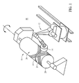
Figure 1 is an illustration of a known fiber placement device. -
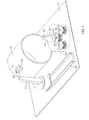
Figure 2 is an illustration of a fiber placement system that includes a layup mandrel mounted to a robot and a stationary fiber placement dispensing system. -
Figure 3 is an illustration of the system ofFigure 2 placing a patch of composite material onto a part. -
Figure 4 is an illustration of the system ofFigure 2 showing the mandrel returning to the fiber-placement delivery system after placement of the patch of composite material. -
Figure 5 is a block diagram of asystem 200 suitable for use with the fiber placement system ofFigures 2-4 . -
Figure 6 is a diagram of one possible system architecture for the controller used in the system ofFigure 5 . -
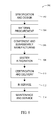
Figure 7 is a flowchart illustrating a process for fabricating and placing a part using the system ofFigures 2-4 . -
Figure 8 is a flow diagram of an aircraft production and service methodology. -
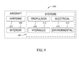
Figure 9 is a block diagram of an aircraft. -
Figure 1 is an illustration of a knownfiber placement device 10 that includes apositioning device 12 and anend effector 14. Thepositioning device 12 is configured to position or otherwise control the movement of theend effector 14. Particularly, thepositioning device 12 is a robotic armature, gantry-type, or post mill type positioning device configured to control multiple axes of movement. -
Fiber placement device 10 is configured to fabricate anitem 16 by applying acourse material 18 on aform 20. Typically, theitem 16 is fabricated from multiple plies or layers, which comprises and series of material courses laid adjacent to one another 18. In various forms, theend effector 14 includes a compaction roller (not shown inFigure 1 ) and/or sweep to apply thecourse material 18 to theform 20. Theform 20 is configured to provide a suitably stable and finished surface for ply placement. As shown, theform 20 is controlled to rotate about an axis. When controlled to rotate thusly, theform 20 is typically referred to as a mandrel. It should be understood that theform 20, or mandrel, may be very complex in shape, depending on the part being fabricated, and may include deep concave surfaces. In other embodiments, theform 20 may be stationary or controlled to move in various axes. For example, theform 20 may be secured to a sliding table or X-Y table. Movement of theform 20, and movement of thepositioning device 12, act to position theend effector 14. - Furthermore, the movement of the
form 20 and thepositioning device 12 is generally coordinated to such a degree that the devices operate essentially as a single unit. Characteristics of theform 20, such as size, shape, contour, and the like, are based upon design parameters of anitem 16. Theitem 16 is shown inFigure 1 being constructed from a plurality ofcourses 24. Each layer of thecourses 24 that is placed upon theform 20 or asubstrate 26 is described as a ply and theitem 16 is typically fabricated from a plurality of plies. Thesubstrate 26 includes theform 20 surface and/or a previously appliedcourse 24. As mentioned above, should the size, shape, and contour of the form become complex, it can be difficult to place theend effector 14 in the proper position, when fabricating a part, without unwanted physical contact occurring between the two. - With regard to the above description of a known fiber placement device, the embodiments described in the following paragraphs are directed to a manufacturing method and system for the placement of fiber. Referring to
Figure 2 , afiber placement system 100 includes alayup mandrel 110 mounted to arobot 112. Thelayup mandrel 110 interfaces with a stationary fiberplacement dispensing system 120 which allows small to mid-size charges to be fabricated using therobot 112 to pass themandrel 110 over the stationary fiberplacement dispensing system 120 in a pattern that results in the fabrication, for example, of apatch 150 of composite material. With regard to the described embodiment, some existing fiber placement machines have the mandrel or tool mounted into a rotary axis in order to build barrel like structures similar to filament winding.Fiber placement system 100 manipulates the layup mandrel in more than one degree of freedom, while fiber placement dispensingsystem 120 remains stationary. - Fiber
placement dispensing system 120 includes acompaction roller 122 proximate a distal end of adelivery head 124, for placement of the fiber onto themandrel 110. As used herein, a delivery head refers to the assembly of systems that can dispense, compact, or cut material. One part ofdelivery head 124 is thecompaction roller 122. It should be noted thatmandrel 110 can be fabricated to have multiple sizes shapes and contours and that one advantage ofstationary dispensing system 120 is that larger spools of fibers can be utilized, as compared to the prior art systems that had to carry the fiber being placed. Another advantage tofiber placement system 100 is that one or morelarger creels 140, sized for suchlarger spools 142 offiber 144, can be located at a fixed station, incorporating a fixed fiber path between thedelivery head 124 and thecreel 140, simplifying the conveying offibers 144 from thecreels 140 to thedelivery head 124. In such an embodiment, thecreels 140 andspools 142 can be remotely mounted from the actual delivery head to provide more clearance for themandrel 110 with respect to thedelivery head 124 thereby allowing for the fabrication of parts incorporating larger contours. In the embodiment shown inFigure 2 ,multiple creels 140 andspools 142 are located within thedispensing system 120 as shown. - More specifically, the complex fiber placement device (dispensing system 120) is fixed and the
robot 112 moves themandrel 110 about thecompaction roller 120 such that the composite material is compacted onto and adheres to themandrel 110. As shown, robot is movable on atrack 160 and has anarticulating arm 162. Further, once the material has been deposited onto the robot-mountedmandrel 110, therobot 112 can then easily move themandrel 110 to a larger assembly, such asbarrel layup 130 and transfer apatch 150 of composite fiber material as shown inFigures 3 and4 . In another embodiment, an automated guided vehicle (AGV) is provided, with the robotic arm mounted thereon, the AGV operable to move the robotic arm for transfer of the composite fiber part from themandrel 110 onto an assembly such asbarrel layup 130. In another embodiment, the composite fiber part as a whole is placed on themandrel 110, without a transfer to other layups. The particular embodiment utilized is at least partially dependent on the size and complexity of the part being fabricated. - With the described embodiments, the conventional solution of laying fiber onto a stationary or single axis rotating mandrel using a dispensing device mounted on a robotic arm is abandoned. Instead, and as further illustrated in
Figure 3 , themandrel 110 is carried by therobot 112 during the application of the fiber to themandrel 110 from the dispensing system and during transfer of thepatch 150 of material to a larger layup, such as may be placed onbarrel layup 130. As shown inFigure 4 , a plurality ofcreels 140 and spools may also be remotely located from dispensingsystem 120, with therespective fibers 144 being fed into dispensing system for routing todelivery head 122. The operation of such an embodiment allows foradditional spools 142 to be utilized simultaneously, for fabrication of multiple fiber parts. In addition, such an arrangement allows for much larger spools offiber 142 to be utilized. -
System 100 includes a material delivery system (dispensing system 120) mounted to thefloor 170 instead of being carried by a motion system as done in currently existing systems. Further, insystem 100, themandrel 110 is mounted to the motion system (robot 112) instead of mounted to thefloor 170 as is the case in currently existing systems. In one embodiment,compaction roller 122 incorporates a single axis of rotation to accommodate different fiber angles and minimize at least a portion of the motion of themandrel 110. In one example, a high aspect ratio mandrel benefits from rotation ofcompaction roller 122 for the 0°/45°/-45°/90° ply orientations commonly utilized without having to spin themandrel 110 through that range of motion. -
System 100 is distinct with respect to existing solutions in that material delivery and application in traditional fiber placement requires a complex electronic, pneumatic and mechanical system. If such a complex system is then mounted on a robot arm, the complexity is compounded by the requirement to carry the electrical and pneumatic cables and hoses to a mobile delivery head. For a creel mounted near, but not on the delivery head, the conveying of the material to the head remains complex. In addition, the weight and size of the mobile delivery head then limits the speed with which the motion system can apply the material. - The size of the mobile delivery head can also limit access in high-contour areas of the part being fabricated. With the embodiments described herein, the
mandrel 110 is a simple solid tool mounted to the robot arm with no control system and no cables or hoses. The complex material delivery components are mounted to the floor as they are a part of the dispensing system. In addition to solving the above mentioned limitations, the floor-mounted delivery system can carry a larger cache of raw materials which will allow less down-time in operation. - Finally,
system 100 affords a solution when it is desired to layup a patch of material, such aspatch 150, and then to transfer thepatch 150 from themandrel 110 to a larger assembly such asbarrel layup 130. Therobot 112 carrying themandrel 110 can simply move thepatch 150 from the delivery system (dispenser 120) to the assembly area (layup barrel 130) with no additional steps. -
Figure 5 is a block diagram of asystem 200 suitable for use with thefiber placement system 100. As shown,system 200 includes acontroller 202. Thecontroller 202 is operable to execute computer readable code. In this regard, thesystem 200 includes a set of computer readable instructions orcode 204. According to thecode 204, thecontroller 202 is configured to access afile 206. Thisfile 206 includes one or more of the following: a computer readable model of the composite item to be fabricated (e.g., patch 150); a computer readable representation of the surface of themandrel 110; a computer readable representation of the surface of thebarrel layup 130; a computer readable representation of the edges of thebarrel layup 130; the thickness of the composite item to be fabricated; a source code based upon at least one of the composite item to be fabricated, themandrel 110, and thebarrel layup 130; a set of movement instructions for therobot 112 based upon the source code; data gathered while laying up the composite item to be fabricated; timestamp information; positional information; identification numbers; and the like. - The
controller 202 is further configured to communicate across anetwork 208. Thenetwork 208 is optionally included to provide additional data storage and/or processing capabilities. In this regard, the network includes adatabase 210 and aserver 212. Thedatabase 210 is configured to store a copy of thecode 204 and/or file 206. Theserver 212 is configured to generate, store, and perform any suitable processing of thecode 204 and/or file 206. In this manner, composite items, such as the composite item (patch 150), generated on computer aided design (CAD) machines such as theserver 212, for example, may be forwarded to thefiber placement system 100. In addition, theserver 212 is operable, via thenetwork 208, to forward updates for thecode 204 and/or file 206. In addition, thesystem 200 optionally includes amemory 214. If present, thememory 214 is configured to store a copy of thecode 204 and/or file 206. - A
positioning device controller 216 is optionally included in thesystem 200 depending upon the requirements of the various actuators and/or servo motors associated withfiber placement system 100. Depending upon the particular configuration of thefiber placement system 100, a plurality of actuators and/or servo motors modulate the rotation, position, speed, direction, and the like of therobot 112, and thus themandrel 110 of thefiber placement system 100. More particularly, these actuators and/or servo motors of therobot 112 are at least configured to modulate the various axes of themandrel 110 and/or control operation of thedispensing system 120, for example, the clamps, tensioners, spools, cutting assemblies and cutters therein. If present, parameters of thepositioning device controller 216 are based upon the specification of the various actuators, servos, and/or thecontroller 202. Thepositioning device controller 216, if present, is configured to control some or all of these actuators and/or servo motors. In addition, these actuators and/or servo motors are optionally operable to be modulated by thecontroller 202 directly, and thus, thesystem 200 may omit thepositioning device controller 216. - The
system 200, optionally, further includes a plurality of sensors configured to sense the various suitable operating conditions or attributes of thefiber placement system 100. Examples of suitable attributes include some or all of the temperature of the fibers and/or mandrel, feed rate and direction, material placement, backing integrity, supply of tow, and/or the like. -
Figure 6 is a possible system architecture forcontroller 202. As shown, thecontroller 202 includes aprocessor 300.Processor 300 is operably connected to apower supply 302,memory 304,clock 306, analog to digital converter (A/D) 308, and an input/output (I/O) port 310. The I/O port 310 is configured to receive signals from any suitably attached electronic device and forward these signals to the A/D 308 and/or theprocessor 300. If the signals are in analog format, the signals may proceed via the A/D 308. In this regard, the A/D 308 is configured to receive analog format signals and convert these signals into corresponding digital format signals. Conversely, the A/D 308 is configured to receive digital format signals from theprocessor 300, convert these signals to analog format, and forward the analog signals to the I/O port 310. In this manner, electronic devices configured to receive analog signals may intercommunicate with theprocessor 300. - The
processor 300 is configured to receive and transmit signals to and from the A/D 308 and/or the I/O port 310. Theprocessor 300 is further configured to receive time signals from theclock 306. In addition, theprocessor 300 is configured to store and retrieve electronic data to and from thememory 304. Furthermore, theprocessor 300 is configured to determine signals operable to modulate thepositioning device controller 216 and thereby control the various actuators and/or servo motors of thefiber placement system 100 to exert a particular force and/or rotate to a particular degree. - In one embodiment, the
processor 300 is configured to execute thecode 204. Based on this set of instructions and signals from the various components of thefiber placement system 100, theprocessor 300 is configured to: determine a set of movement instructions for the robot 112 (and themandrel 110 attached thereto), provide instructions to dispensingsystem 120 for the disbursement of fiber and the like. -
Figure 7 is aflowchart 400 illustrating a process for fabricating and placing a part using thefiber placement system 100 described herein. A program for manufacturing a specific part is selected 402. A mandrel appropriate for the selected part is affixed 404 to the robotic arm. The selected program is then executed 406 to cause the robotic arm to move the mandrel with respect to the compaction roller and delivery head of the fiber-placement delivery system as the fiber-placement delivery system dispenses the fiber onto the mandrel. When fabrication of the part is completed, the mandrel is moved 408 to the location where the part is to be placed onto a tool and the part is released 410 from the mandrel onto the tool. - The described embodiments are generally related to a fiber placement system that includes a robot or other numeric controlled motion system, a fiber-placement layup mandrel mounted on the motion system, a stationary-mounted fiber-placement delivery system, and control software to guide the robot (and hence the mandrel) while also controlling the fiber-placement delivery system. Generally, while such embodiments are not limited in size or configuration, the described system is particularly useful for performing fiber-placement of composite charges on small to mid-size parts. Size of such parts is limited only by the load carrying capacity of the device utilized to manipulate the mandrel. In addition, this system can be used to transfer intermediate patches (doublers) of composite material from the fiber-placement area to larger layups such as fuselage barrels.
- Embodiments of the disclosure may be described in the context of aircraft manufacturing and
service method 500 as shown inFigure 8 and anaircraft 600 as shown inFigure 9 . During pre-production, aircraft manufacturing andservice method 500 may include specification anddesign 502 ofaircraft 600 andmaterial procurement 504. - During production, component and
subassembly manufacturing 506 andsystem integration 508 ofaircraft 600 takes place. Thereafter,aircraft 600 may go through certification anddelivery 510 in order to be placed inservice 512. While in service by a customer,aircraft 600 is scheduled for routine maintenance and service 514 (which may also include modification, reconfiguration, refurbishment, and so on). - Each of the processes of aircraft manufacturing and
service method 500 may be performed or carried out by a system integrator, a third party, and/or an operator (e.g., a customer). For the purposes of this description, a system integrator may include, without limitation, any number of aircraft manufacturers and major-system subcontractors; a third party may include, for example, without limitation, any number of venders, subcontractors, and suppliers; and an operator may be an airline, leasing company, military entity, service organization, and so on. - As shown in
Figure 9 ,aircraft 600 produced by aircraft manufacturing andservice method 500 may includeairframe 602 with a plurality ofsystems 604 and interior 606. Examples ofsystems 604 include one or more ofpropulsion system 608,electrical system 610,hydraulic system 612, andenvironmental system 614. Any number of other systems may be included in this example. Although an aerospace example is shown, the principles of the disclosure may be applied to other industries, such as the automotive industry. - Apparatus and methods embodied herein may be employed during any one or more of the stages of aircraft manufacturing and
service method 500. For example, without limitation, components or subassemblies corresponding to component andsubassembly manufacturing 506 may be fabricated or manufactured in a manner similar to components or subassemblies produced whileaircraft 600 is in service. - Also, one or more apparatus embodiments, method embodiments, or a combination thereof may be utilized during component and
subassembly manufacturing 506 andsystem integration 508, for example, without limitation, by substantially expediting assembly of or reducing the cost ofaircraft 600. Similarly, one or more of apparatus embodiments, method embodiments, or a combination thereof may be utilized whileaircraft 600 is in service, for example, without limitation, to maintenance andservice 514 may be used duringsystem integration 508 and/or maintenance andservice 514 to determine whether parts may be connected and/or mated to each other. - The description of the different advantageous embodiments has been presented for purposes of illustration and description, and is not intended to be exhaustive or limited to the embodiments in the form disclosed. Many modifications and variations will be apparent to those of ordinary skill in the art. Further, different advantageous embodiments may provide different advantages as compared to other advantageous embodiments. The embodiment or embodiments selected are chosen and described in order to best explain the principles of the embodiments, the practical application, and to enable others of ordinary skill in the art to understand the disclosure for various embodiments with various modifications as are suited to the particular use contemplated.
- This written description uses examples to disclose various embodiments, which include the best mode, to enable any person skilled in the art to practice those embodiments, including making and using any devices or systems and performing any incorporated methods. The patentable scope is defined by the claims, and may include other examples that occur to those skilled in the art. Such other examples are intended to be within the scope of the claims if they have structural elements that do not differ from the literal language of the claims, or if they include equivalent structural elements with insubstantial differences from the literal languages of the claims.
-
- 1. A method for fabrication of a composite fiber part, said method comprising:
- placing a mandrel for fabrication of a selected part onto a robotic arm; and operating the robotic arm to move the mandrel with respect to a delivery head of a stationary fiber-placement delivery system as the fiber-placement delivery system dispenses the composite fiber onto the selected mandrel further comprising: moving the mandrel to a location where the fabricated composite fiber part is to be placed onto a tool; and releasing the part from the mandrel.
- 2. A method for fabrication of a composite fiber part, said method comprising:
- placing a mandrel for fabrication of a selected part onto a robotic arm; and operating the robotic arm to move the mandrel with respect to a delivery head of a stationary fiber-placement delivery system as the fiber-placement delivery system dispenses the composite fiber onto the selected mandrel further comprising moving the robotic arm along a track for transfer of the fabricated composite fiber part from the mandrel to an assembly.
- 3. A method for fabrication of a composite fiber part, said method comprising:
- placing a mandrel for fabrication of a selected part onto a robotic arm; and operating the robotic arm to move the mandrel with respect to a delivery head of a stationary fiber-placement delivery system as the fiber-placement delivery system dispenses the composite fiber onto the selected mandrel further comprising executing a program to operate material delivery components within the fiber-placement delivery system for delivery of fiber to the delivery head.
- 4. A method for fabrication of a composite fiber part, said method comprising:
- placing a mandrel for fabrication of a selected part onto a robotic arm; and operating the robotic arm to move the mandrel with respect to a delivery head of a stationary fiber-placement delivery system as the fiber-placement delivery system dispenses the composite fiber onto the selected mandrel wherein operating the robotic arm to move the mandrel with respect to a delivery head of a stationary fiber-placement delivery system comprises executing a program within a processing device to guide the robotic arm and control operation of the fiber-placement delivery system.
- 5. The method according to Clause 4 wherein executing a program within a processing device to guide the robotic arm and control operation of the fiber-placement delivery system comprises at least one of: executing a program providing a computer readable model of the composite fiber part to be fabricated; executing a program providing a computer readable representation of a surface of the selected mandrel; and executing a program providing a computer readable representation of a surface onto which the composite fiber part is to be placed.
- 6. The method according to Clause 4 wherein executing a program within a processing device to guide the robotic arm and control operation of the fiber-placement delivery system comprises executing a set of movement instructions for a motion system associated with the robotic arm and a set of instructions for dispensing fiber material from the fiber-placement delivery system.
- 7. A fiber placement system comprising a fiber-placement layup mandrel mounted on a robotic arm; and a stationary fiber-placement delivery system, said robotic arm operable for movement of said mandrel with respect to said stationary fiber-placement delivery system.
- 8. The fiber placement system of Clause 7 comprising at least one of a track mounted motion system and an automated guided vehicle upon which said robotic arm is mounted.
Claims (15)
- A fiber placement system comprising:a motion system comprising a robotic arm;a fiber-placement layup mandrel mounted on said robotic arm; anda fiber-placement delivery system comprising a delivery head, said robotic arm operable for movement of said mandrel with respect to and proximate said delivery head for fabrication of a composite fiber part.
- The fiber placement system according to Claim 1 wherein said delivery head is stationary.
- The fiber placement system according to Claim 1 wherein said fiber-placement layup mandrel comprises a plurality of mandrels, said mandrels removable from said robotic arm, and fabricated to have multiple sizes, shapes, and contours for fabrication of multiple parts.
- The fiber placement system according to Claim 1 wherein said motion system comprises a track, said robotic arm movable along said track for transfer of the composite fiber part from said mandrel onto an assembly.
- The fiber placement system according to Claim 1 wherein said motion system comprises an automated guided vehicle operable to move said robotic arm for transfer of the composite fiber part from said mandrel onto an assembly.
- The fiber placement system according to Claim 1 wherein said robotic arm comprises an articulating arm.
- The fiber placement system according to Claim 1 wherein said fiber-placement delivery system comprises material delivery components operable for delivery of fiber to said delivery head.
- The fiber placement system according to Claim 1 wherein said fiber-placement delivery system comprises:a stationary system mounted to a surface; anda delivery head operably attached to said stationary system, said delivery head comprising a compaction roller at a distal end thereof, said compaction roller having a single axis of rotation.
- The fiber placement system according to Claim 1 further comprising a processing device programmed to guide said robotic arm and control operation of said fiber-placement delivery system.
- The fiber placement system according to Claim 9 wherein said processing device is programmed with at least one of a computer readable model of the composite fiber part to be fabricated, a computer readable representation of a surface of said mandrel, a computer readable representation of a surface onto which the composite fiber part is to be placed, and a thickness of the composite fiber part to be fabricated.
- The fiber placement system according to Claim 9 wherein said processing device is programmed with at least one of a set of movement instructions for said motion system and a set of instructions for dispensing fiber material from said fiber-placement delivery system.
- The fiber placement system according to Claim 1 wherein said robotic arm is operable for movement of said mandrel through more than one degree of freedom.
- A method for fabrication of a composite fiber part, said method comprising:placing a mandrel for fabrication of a selected part onto a robotic arm; andoperating the robotic arm to move the mandrel with respect to a delivery head of a stationary fiber-placement delivery system as the fiber-placement delivery system dispenses the composite fiber onto the selected mandrel.
- The method according to Claim 13 wherein operating the robotic arm to move the mandrel comprises executing a selected program to operate the robotic arm and cause the stationary fiber-placement delivery system to dispense the composite fiber through a delivery head.
- The method according to Claim 13 further comprising selecting a program associated with a composite fiber part to be fabricated.
Applications Claiming Priority (1)
| Application Number | Priority Date | Filing Date | Title |
|---|---|---|---|
| US12/969,106 US20120152432A1 (en) | 2010-12-15 | 2010-12-15 | Methods and systems for fiber placement using a stationary dispenser |
Publications (2)
| Publication Number | Publication Date |
|---|---|
| EP2465668A1 true EP2465668A1 (en) | 2012-06-20 |
| EP2465668B1 EP2465668B1 (en) | 2016-05-18 |
Family
ID=45406456
Family Applications (1)
| Application Number | Title | Priority Date | Filing Date |
|---|---|---|---|
| EP11193564.9A Active EP2465668B1 (en) | 2010-12-15 | 2011-12-14 | Fibre placement system and method |
Country Status (6)
| Country | Link |
|---|---|
| US (1) | US20120152432A1 (en) |
| EP (1) | EP2465668B1 (en) |
| JP (1) | JP5822696B2 (en) |
| CN (1) | CN102529114B (en) |
| CA (1) | CA2756803A1 (en) |
| ES (1) | ES2574304T3 (en) |
Cited By (1)
| Publication number | Priority date | Publication date | Assignee | Title |
|---|---|---|---|---|
| CN103358564A (en) * | 2013-07-05 | 2013-10-23 | 西安交通大学 | Integral wind-power blade ultraviolet light/electron beam in situ curing fiber laying forming device and integral wind-power blade ultraviolet light/electron beam in situ curing fiber laying forming method |
Families Citing this family (11)
| Publication number | Priority date | Publication date | Assignee | Title |
|---|---|---|---|---|
| US9481158B2 (en) | 2013-07-11 | 2016-11-01 | The Boeing Company | Short course fiber placement head |
| SG11201607911SA (en) | 2014-03-28 | 2016-10-28 | Composite Cluster Singapore Pte Ltd | Freespace composite manufacturing process and device |
| CN104570955B (en) * | 2014-11-24 | 2018-06-22 | 中国科学院自动化研究所 | A kind of composite material automatic fiber placement machine control system and control method |
| CN104608398B (en) * | 2015-02-16 | 2017-03-01 | 徐剑 | A kind of laying method of fibrous composite parts preforming and equipment |
| GB2551247A (en) * | 2016-04-13 | 2017-12-13 | Composite Cluster Singapore Pte Ltd | Active steering end-effector for composite processing and polymer processing heat source |
| CN110723271B (en) * | 2018-07-16 | 2024-07-30 | 波音公司 | Apparatus and method for making composite structures and reacting to placement forces |
| EP4041536A4 (en) * | 2019-10-07 | 2024-02-14 | Fives Machining Systems, Inc. | W-axis fiber placement head |
| JP7640681B2 (en) | 2020-09-04 | 2025-03-05 | フィブ・マシニング・システムズ,インコーポレーテッド | Fiber Placement Machine Including Composite Tape Film Removal |
| JP7822749B2 (en) * | 2020-11-18 | 2026-03-03 | ザ・ボーイング・カンパニー | Dynamic mapping for moving parts within a manufacturing environment |
| US11724467B2 (en) * | 2020-12-18 | 2023-08-15 | The Boeing Company | System and method for laying up composite barrel shaped structures |
| WO2026014447A1 (en) * | 2024-07-09 | 2026-01-15 | 川崎重工業株式会社 | Processing method |
Citations (2)
| Publication number | Priority date | Publication date | Assignee | Title |
|---|---|---|---|---|
| WO2009062749A1 (en) * | 2007-11-15 | 2009-05-22 | Airbus Deutschland Gmbh | Method and device for producing a fiber composite component |
| EP2402147A1 (en) * | 2010-05-12 | 2012-01-04 | Mag Ias Llc. | Robotic based fiber placement cell with stationary dispensing head and creel |
Family Cites Families (12)
| Publication number | Priority date | Publication date | Assignee | Title |
|---|---|---|---|---|
| GB8328211D0 (en) * | 1983-10-21 | 1983-11-23 | Atomic Energy Authority Uk | Filament winding |
| US5454897A (en) * | 1994-05-02 | 1995-10-03 | Cincinnati Milacron Inc. | Presser member for fiber laying machine |
| US6073670A (en) * | 1997-10-31 | 2000-06-13 | Isogrid Composites, Inc. | Multiple fiber placement head arrangement for placing fibers into channels of a mold |
| US6038949A (en) * | 1998-09-14 | 2000-03-21 | Nv Owens-Corning S.A. | Method for dispensing reinforcement fibers |
| US7282107B2 (en) * | 2003-08-22 | 2007-10-16 | The Boeing Company | Multiple head automated composite laminating machine for the fabrication of large barrel section components |
| DE102004056284B4 (en) * | 2004-11-22 | 2010-08-26 | Airbus Deutschland Gmbh | Device for transporting components for transport |
| US7472736B2 (en) * | 2005-02-14 | 2009-01-06 | The Boeing Company | Modular head lamination device and method |
| US7516944B2 (en) * | 2006-04-18 | 2009-04-14 | Cincinnati Machine, Llc | Swiveling and tilting roller axis for web guiding in a fiber placement machine |
| US20090084486A1 (en) * | 2007-09-27 | 2009-04-02 | The Boeing Company | Optimized ordering of doubler plies in composite structures |
| US8916010B2 (en) * | 2007-12-07 | 2014-12-23 | The Boeing Company | Composite manufacturing method |
| US8557074B2 (en) * | 2008-02-27 | 2013-10-15 | The Boeing Company | Reduced complexity automatic fiber placement apparatus and method |
| US20100200168A1 (en) * | 2009-02-06 | 2010-08-12 | Ingersoll Machine Tools, Inc. | Fiber delivery apparatus and system having a creel and fiber placement head sans fiber redirect |
-
2010
- 2010-12-15 US US12/969,106 patent/US20120152432A1/en not_active Abandoned
-
2011
- 2011-11-01 CA CA2756803A patent/CA2756803A1/en not_active Abandoned
- 2011-11-22 CN CN201110386092.8A patent/CN102529114B/en active Active
- 2011-12-02 JP JP2011264490A patent/JP5822696B2/en active Active
- 2011-12-14 EP EP11193564.9A patent/EP2465668B1/en active Active
- 2011-12-14 ES ES11193564.9T patent/ES2574304T3/en active Active
Patent Citations (2)
| Publication number | Priority date | Publication date | Assignee | Title |
|---|---|---|---|---|
| WO2009062749A1 (en) * | 2007-11-15 | 2009-05-22 | Airbus Deutschland Gmbh | Method and device for producing a fiber composite component |
| EP2402147A1 (en) * | 2010-05-12 | 2012-01-04 | Mag Ias Llc. | Robotic based fiber placement cell with stationary dispensing head and creel |
Cited By (2)
| Publication number | Priority date | Publication date | Assignee | Title |
|---|---|---|---|---|
| CN103358564A (en) * | 2013-07-05 | 2013-10-23 | 西安交通大学 | Integral wind-power blade ultraviolet light/electron beam in situ curing fiber laying forming device and integral wind-power blade ultraviolet light/electron beam in situ curing fiber laying forming method |
| CN103358564B (en) * | 2013-07-05 | 2015-12-02 | 西安交通大学 | Integral wind power blade ultraviolet light/electron beam in-situ cured fiber placement shaped device and method |
Also Published As
| Publication number | Publication date |
|---|---|
| JP2012126134A (en) | 2012-07-05 |
| US20120152432A1 (en) | 2012-06-21 |
| CN102529114A (en) | 2012-07-04 |
| EP2465668B1 (en) | 2016-05-18 |
| ES2574304T3 (en) | 2016-06-16 |
| CN102529114B (en) | 2016-03-02 |
| CA2756803A1 (en) | 2012-06-15 |
| JP5822696B2 (en) | 2015-11-24 |
Similar Documents
| Publication | Publication Date | Title |
|---|---|---|
| EP2465668B1 (en) | Fibre placement system and method | |
| US10717225B2 (en) | Drape forming end effector | |
| AU2013325199B2 (en) | Method of composite tape lamination over convex radii | |
| US8454788B2 (en) | Method and apparatus for placing short courses of composite tape | |
| US8557074B2 (en) | Reduced complexity automatic fiber placement apparatus and method | |
| EP3119592B1 (en) | Flexible fiber placement system for small composite parts manufacturing and methods | |
| US10137648B2 (en) | Material placement system | |
| US12077319B2 (en) | Fabrication line, systems, and methods for fuselage sections | |
| US12030265B2 (en) | Forming a curvature into a charge | |
| WO2010091359A2 (en) | Fiber delivery apparatus and system having a creel and fiber placement head sans fiber redirect | |
| EP4000845B1 (en) | Fabrication systems and methods for fuselage sections | |
| US9522506B2 (en) | Methods for composite tape lamination over various angles between fibers and lines tangent to convex radii | |
| CN114644133A (en) | System and method for laying composite tubular structures | |
| EP4000888B1 (en) | Continuously moving line for making composite laminate parts | |
| EP4000847B1 (en) | Fabrication system for fuselage sections | |
| NL2027417B1 (en) | Fabrication line, systems, and methods for fuselage sections | |
| NL2027415B1 (en) | Fabrication line, systems, and methods for fuselage sections | |
| NL2027419B1 (en) | Fabrication line, systems, and methods for fuselage sections | |
| EP4000846A1 (en) | Fabrication line and systems for fuselage sections |
Legal Events
| Date | Code | Title | Description |
|---|---|---|---|
| PUAI | Public reference made under article 153(3) epc to a published international application that has entered the european phase |
Free format text: ORIGINAL CODE: 0009012 |
|
| 17P | Request for examination filed |
Effective date: 20111214 |
|
| AK | Designated contracting states |
Kind code of ref document: A1 Designated state(s): AL AT BE BG CH CY CZ DE DK EE ES FI FR GB GR HR HU IE IS IT LI LT LU LV MC MK MT NL NO PL PT RO RS SE SI SK SM TR |
|
| AX | Request for extension of the european patent |
Extension state: BA ME |
|
| GRAP | Despatch of communication of intention to grant a patent |
Free format text: ORIGINAL CODE: EPIDOSNIGR1 |
|
| RIC1 | Information provided on ipc code assigned before grant |
Ipc: B29C 70/38 20060101AFI20130301BHEP |
|
| INTG | Intention to grant announced |
Effective date: 20130325 |
|
| 17Q | First examination report despatched |
Effective date: 20140327 |
|
| INTG | Intention to grant announced |
Effective date: 20151125 |
|
| GRAS | Grant fee paid |
Free format text: ORIGINAL CODE: EPIDOSNIGR3 |
|
| GRAA | (expected) grant |
Free format text: ORIGINAL CODE: 0009210 |
|
| AK | Designated contracting states |
Kind code of ref document: B1 Designated state(s): AL AT BE BG CH CY CZ DE DK EE ES FI FR GB GR HR HU IE IS IT LI LT LU LV MC MK MT NL NO PL PT RO RS SE SI SK SM TR |
|
| REG | Reference to a national code |
Ref country code: GB Ref legal event code: FG4D |
|
| REG | Reference to a national code |
Ref country code: CH Ref legal event code: EP |
|
| REG | Reference to a national code |
Ref country code: IE Ref legal event code: FG4D Ref country code: AT Ref legal event code: REF Ref document number: 800055 Country of ref document: AT Kind code of ref document: T Effective date: 20160615 |
|
| REG | Reference to a national code |
Ref country code: ES Ref legal event code: FG2A Ref document number: 2574304 Country of ref document: ES Kind code of ref document: T3 Effective date: 20160616 |
|
| REG | Reference to a national code |
Ref country code: DE Ref legal event code: R096 Ref document number: 602011026674 Country of ref document: DE |
|
| REG | Reference to a national code |
Ref country code: NL Ref legal event code: MP Effective date: 20160518 |
|
| REG | Reference to a national code |
Ref country code: LT Ref legal event code: MG4D |
|
| PG25 | Lapsed in a contracting state [announced via postgrant information from national office to epo] |
Ref country code: NL Free format text: LAPSE BECAUSE OF FAILURE TO SUBMIT A TRANSLATION OF THE DESCRIPTION OR TO PAY THE FEE WITHIN THE PRESCRIBED TIME-LIMIT Effective date: 20160518 Ref country code: FI Free format text: LAPSE BECAUSE OF FAILURE TO SUBMIT A TRANSLATION OF THE DESCRIPTION OR TO PAY THE FEE WITHIN THE PRESCRIBED TIME-LIMIT Effective date: 20160518 Ref country code: NO Free format text: LAPSE BECAUSE OF FAILURE TO SUBMIT A TRANSLATION OF THE DESCRIPTION OR TO PAY THE FEE WITHIN THE PRESCRIBED TIME-LIMIT Effective date: 20160818 Ref country code: LT Free format text: LAPSE BECAUSE OF FAILURE TO SUBMIT A TRANSLATION OF THE DESCRIPTION OR TO PAY THE FEE WITHIN THE PRESCRIBED TIME-LIMIT Effective date: 20160518 |
|
| REG | Reference to a national code |
Ref country code: AT Ref legal event code: MK05 Ref document number: 800055 Country of ref document: AT Kind code of ref document: T Effective date: 20160518 |
|
| PG25 | Lapsed in a contracting state [announced via postgrant information from national office to epo] |
Ref country code: LV Free format text: LAPSE BECAUSE OF FAILURE TO SUBMIT A TRANSLATION OF THE DESCRIPTION OR TO PAY THE FEE WITHIN THE PRESCRIBED TIME-LIMIT Effective date: 20160518 Ref country code: SE Free format text: LAPSE BECAUSE OF FAILURE TO SUBMIT A TRANSLATION OF THE DESCRIPTION OR TO PAY THE FEE WITHIN THE PRESCRIBED TIME-LIMIT Effective date: 20160518 Ref country code: GR Free format text: LAPSE BECAUSE OF FAILURE TO SUBMIT A TRANSLATION OF THE DESCRIPTION OR TO PAY THE FEE WITHIN THE PRESCRIBED TIME-LIMIT Effective date: 20160819 Ref country code: PT Free format text: LAPSE BECAUSE OF FAILURE TO SUBMIT A TRANSLATION OF THE DESCRIPTION OR TO PAY THE FEE WITHIN THE PRESCRIBED TIME-LIMIT Effective date: 20160919 Ref country code: HR Free format text: LAPSE BECAUSE OF FAILURE TO SUBMIT A TRANSLATION OF THE DESCRIPTION OR TO PAY THE FEE WITHIN THE PRESCRIBED TIME-LIMIT Effective date: 20160518 Ref country code: RS Free format text: LAPSE BECAUSE OF FAILURE TO SUBMIT A TRANSLATION OF THE DESCRIPTION OR TO PAY THE FEE WITHIN THE PRESCRIBED TIME-LIMIT Effective date: 20160518 |
|
| REG | Reference to a national code |
Ref country code: FR Ref legal event code: PLFP Year of fee payment: 6 |
|
| PG25 | Lapsed in a contracting state [announced via postgrant information from national office to epo] |
Ref country code: EE Free format text: LAPSE BECAUSE OF FAILURE TO SUBMIT A TRANSLATION OF THE DESCRIPTION OR TO PAY THE FEE WITHIN THE PRESCRIBED TIME-LIMIT Effective date: 20160518 Ref country code: SK Free format text: LAPSE BECAUSE OF FAILURE TO SUBMIT A TRANSLATION OF THE DESCRIPTION OR TO PAY THE FEE WITHIN THE PRESCRIBED TIME-LIMIT Effective date: 20160518 Ref country code: RO Free format text: LAPSE BECAUSE OF FAILURE TO SUBMIT A TRANSLATION OF THE DESCRIPTION OR TO PAY THE FEE WITHIN THE PRESCRIBED TIME-LIMIT Effective date: 20160518 Ref country code: CZ Free format text: LAPSE BECAUSE OF FAILURE TO SUBMIT A TRANSLATION OF THE DESCRIPTION OR TO PAY THE FEE WITHIN THE PRESCRIBED TIME-LIMIT Effective date: 20160518 Ref country code: DK Free format text: LAPSE BECAUSE OF FAILURE TO SUBMIT A TRANSLATION OF THE DESCRIPTION OR TO PAY THE FEE WITHIN THE PRESCRIBED TIME-LIMIT Effective date: 20160518 |
|
| REG | Reference to a national code |
Ref country code: DE Ref legal event code: R097 Ref document number: 602011026674 Country of ref document: DE |
|
| PG25 | Lapsed in a contracting state [announced via postgrant information from national office to epo] |
Ref country code: PL Free format text: LAPSE BECAUSE OF FAILURE TO SUBMIT A TRANSLATION OF THE DESCRIPTION OR TO PAY THE FEE WITHIN THE PRESCRIBED TIME-LIMIT Effective date: 20160518 Ref country code: BE Free format text: LAPSE BECAUSE OF FAILURE TO SUBMIT A TRANSLATION OF THE DESCRIPTION OR TO PAY THE FEE WITHIN THE PRESCRIBED TIME-LIMIT Effective date: 20160518 Ref country code: AT Free format text: LAPSE BECAUSE OF FAILURE TO SUBMIT A TRANSLATION OF THE DESCRIPTION OR TO PAY THE FEE WITHIN THE PRESCRIBED TIME-LIMIT Effective date: 20160518 Ref country code: SM Free format text: LAPSE BECAUSE OF FAILURE TO SUBMIT A TRANSLATION OF THE DESCRIPTION OR TO PAY THE FEE WITHIN THE PRESCRIBED TIME-LIMIT Effective date: 20160518 |
|
| PLBE | No opposition filed within time limit |
Free format text: ORIGINAL CODE: 0009261 |
|
| STAA | Information on the status of an ep patent application or granted ep patent |
Free format text: STATUS: NO OPPOSITION FILED WITHIN TIME LIMIT |
|
| 26N | No opposition filed |
Effective date: 20170221 |
|
| PG25 | Lapsed in a contracting state [announced via postgrant information from national office to epo] |
Ref country code: SI Free format text: LAPSE BECAUSE OF FAILURE TO SUBMIT A TRANSLATION OF THE DESCRIPTION OR TO PAY THE FEE WITHIN THE PRESCRIBED TIME-LIMIT Effective date: 20160518 |
|
| PG25 | Lapsed in a contracting state [announced via postgrant information from national office to epo] |
Ref country code: MC Free format text: LAPSE BECAUSE OF FAILURE TO SUBMIT A TRANSLATION OF THE DESCRIPTION OR TO PAY THE FEE WITHIN THE PRESCRIBED TIME-LIMIT Effective date: 20160518 |
|
| REG | Reference to a national code |
Ref country code: CH Ref legal event code: PL |
|
| REG | Reference to a national code |
Ref country code: IE Ref legal event code: MM4A |
|
| PG25 | Lapsed in a contracting state [announced via postgrant information from national office to epo] |
Ref country code: CH Free format text: LAPSE BECAUSE OF NON-PAYMENT OF DUE FEES Effective date: 20161231 Ref country code: LU Free format text: LAPSE BECAUSE OF NON-PAYMENT OF DUE FEES Effective date: 20161214 Ref country code: LI Free format text: LAPSE BECAUSE OF NON-PAYMENT OF DUE FEES Effective date: 20161231 |
|
| PG25 | Lapsed in a contracting state [announced via postgrant information from national office to epo] |
Ref country code: IE Free format text: LAPSE BECAUSE OF NON-PAYMENT OF DUE FEES Effective date: 20161214 |
|
| REG | Reference to a national code |
Ref country code: FR Ref legal event code: PLFP Year of fee payment: 7 |
|
| PG25 | Lapsed in a contracting state [announced via postgrant information from national office to epo] |
Ref country code: HU Free format text: LAPSE BECAUSE OF FAILURE TO SUBMIT A TRANSLATION OF THE DESCRIPTION OR TO PAY THE FEE WITHIN THE PRESCRIBED TIME-LIMIT; INVALID AB INITIO Effective date: 20111214 Ref country code: CY Free format text: LAPSE BECAUSE OF FAILURE TO SUBMIT A TRANSLATION OF THE DESCRIPTION OR TO PAY THE FEE WITHIN THE PRESCRIBED TIME-LIMIT Effective date: 20160518 |
|
| PG25 | Lapsed in a contracting state [announced via postgrant information from national office to epo] |
Ref country code: MK Free format text: LAPSE BECAUSE OF FAILURE TO SUBMIT A TRANSLATION OF THE DESCRIPTION OR TO PAY THE FEE WITHIN THE PRESCRIBED TIME-LIMIT Effective date: 20160518 Ref country code: TR Free format text: LAPSE BECAUSE OF FAILURE TO SUBMIT A TRANSLATION OF THE DESCRIPTION OR TO PAY THE FEE WITHIN THE PRESCRIBED TIME-LIMIT Effective date: 20160518 Ref country code: IS Free format text: LAPSE BECAUSE OF FAILURE TO SUBMIT A TRANSLATION OF THE DESCRIPTION OR TO PAY THE FEE WITHIN THE PRESCRIBED TIME-LIMIT Effective date: 20160518 |
|
| PG25 | Lapsed in a contracting state [announced via postgrant information from national office to epo] |
Ref country code: BG Free format text: LAPSE BECAUSE OF FAILURE TO SUBMIT A TRANSLATION OF THE DESCRIPTION OR TO PAY THE FEE WITHIN THE PRESCRIBED TIME-LIMIT Effective date: 20160518 |
|
| PG25 | Lapsed in a contracting state [announced via postgrant information from national office to epo] |
Ref country code: MT Free format text: LAPSE BECAUSE OF NON-PAYMENT OF DUE FEES Effective date: 20161214 |
|
| PG25 | Lapsed in a contracting state [announced via postgrant information from national office to epo] |
Ref country code: AL Free format text: LAPSE BECAUSE OF FAILURE TO SUBMIT A TRANSLATION OF THE DESCRIPTION OR TO PAY THE FEE WITHIN THE PRESCRIBED TIME-LIMIT Effective date: 20160518 |
|
| P01 | Opt-out of the competence of the unified patent court (upc) registered |
Effective date: 20230516 |
|
| PGFP | Annual fee paid to national office [announced via postgrant information from national office to epo] |
Ref country code: GB Payment date: 20251229 Year of fee payment: 15 |
|
| PGFP | Annual fee paid to national office [announced via postgrant information from national office to epo] |
Ref country code: IT Payment date: 20251219 Year of fee payment: 15 |
|
| PGFP | Annual fee paid to national office [announced via postgrant information from national office to epo] |
Ref country code: FR Payment date: 20251226 Year of fee payment: 15 |
|
| PGFP | Annual fee paid to national office [announced via postgrant information from national office to epo] |
Ref country code: ES Payment date: 20260102 Year of fee payment: 15 |
|
| PGFP | Annual fee paid to national office [announced via postgrant information from national office to epo] |
Ref country code: DE Payment date: 20251229 Year of fee payment: 15 |