EP2465664B1 - Mobile-plate assembly for a thermoforming station - Google Patents
Mobile-plate assembly for a thermoforming station Download PDFInfo
- Publication number
- EP2465664B1 EP2465664B1 EP11194507.7A EP11194507A EP2465664B1 EP 2465664 B1 EP2465664 B1 EP 2465664B1 EP 11194507 A EP11194507 A EP 11194507A EP 2465664 B1 EP2465664 B1 EP 2465664B1
- Authority
- EP
- European Patent Office
- Prior art keywords
- plate assembly
- mobile
- bar member
- bar
- window
- Prior art date
- Legal status (The legal status is an assumption and is not a legal conclusion. Google has not performed a legal analysis and makes no representation as to the accuracy of the status listed.)
- Not-in-force
Links
- 238000003856 thermoforming Methods 0.000 title claims description 26
- 239000002985 plastic film Substances 0.000 claims description 11
- 239000004033 plastic Substances 0.000 claims description 10
- 239000000463 material Substances 0.000 claims description 9
- 230000002093 peripheral effect Effects 0.000 claims description 4
- 238000007789 sealing Methods 0.000 claims description 2
- 230000000712 assembly Effects 0.000 description 6
- 238000000429 assembly Methods 0.000 description 6
- 239000012815 thermoplastic material Substances 0.000 description 6
- 230000004048 modification Effects 0.000 description 2
- 238000012986 modification Methods 0.000 description 2
- 229920001169 thermoplastic Polymers 0.000 description 2
- 239000004416 thermosoftening plastic Substances 0.000 description 2
- XAGFODPZIPBFFR-UHFFFAOYSA-N aluminium Chemical compound [Al] XAGFODPZIPBFFR-UHFFFAOYSA-N 0.000 description 1
- 229910052782 aluminium Inorganic materials 0.000 description 1
- 239000004411 aluminium Substances 0.000 description 1
- 230000005540 biological transmission Effects 0.000 description 1
- 238000010586 diagram Methods 0.000 description 1
- 238000004519 manufacturing process Methods 0.000 description 1
Images


Classifications
-
- B—PERFORMING OPERATIONS; TRANSPORTING
- B29—WORKING OF PLASTICS; WORKING OF SUBSTANCES IN A PLASTIC STATE IN GENERAL
- B29C—SHAPING OR JOINING OF PLASTICS; SHAPING OF MATERIAL IN A PLASTIC STATE, NOT OTHERWISE PROVIDED FOR; AFTER-TREATMENT OF THE SHAPED PRODUCTS, e.g. REPAIRING
- B29C51/00—Shaping by thermoforming, i.e. shaping sheets or sheet like preforms after heating, e.g. shaping sheets in matched moulds or by deep-drawing; Apparatus therefor
- B29C51/26—Component parts, details or accessories; Auxiliary operations
- B29C51/261—Handling means, e.g. transfer means, feeding means
- B29C51/262—Clamping means for the sheets, e.g. clamping frames
-
- B—PERFORMING OPERATIONS; TRANSPORTING
- B29—WORKING OF PLASTICS; WORKING OF SUBSTANCES IN A PLASTIC STATE IN GENERAL
- B29C—SHAPING OR JOINING OF PLASTICS; SHAPING OF MATERIAL IN A PLASTIC STATE, NOT OTHERWISE PROVIDED FOR; AFTER-TREATMENT OF THE SHAPED PRODUCTS, e.g. REPAIRING
- B29C2791/00—Shaping characteristics in general
- B29C2791/004—Shaping under special conditions
- B29C2791/006—Using vacuum
-
- B—PERFORMING OPERATIONS; TRANSPORTING
- B29—WORKING OF PLASTICS; WORKING OF SUBSTANCES IN A PLASTIC STATE IN GENERAL
- B29C—SHAPING OR JOINING OF PLASTICS; SHAPING OF MATERIAL IN A PLASTIC STATE, NOT OTHERWISE PROVIDED FOR; AFTER-TREATMENT OF THE SHAPED PRODUCTS, e.g. REPAIRING
- B29C2791/00—Shaping characteristics in general
- B29C2791/004—Shaping under special conditions
- B29C2791/007—Using fluid under pressure
-
- B—PERFORMING OPERATIONS; TRANSPORTING
- B29—WORKING OF PLASTICS; WORKING OF SUBSTANCES IN A PLASTIC STATE IN GENERAL
- B29C—SHAPING OR JOINING OF PLASTICS; SHAPING OF MATERIAL IN A PLASTIC STATE, NOT OTHERWISE PROVIDED FOR; AFTER-TREATMENT OF THE SHAPED PRODUCTS, e.g. REPAIRING
- B29C51/00—Shaping by thermoforming, i.e. shaping sheets or sheet like preforms after heating, e.g. shaping sheets in matched moulds or by deep-drawing; Apparatus therefor
- B29C51/08—Deep drawing or matched-mould forming, i.e. using mechanical means only
Definitions
- the present invention relates to a mobile-plate assembly which is suitable to provide an adjustable reduction window for holding or supporting sheets of different sizes of thermoplastic material in a thermoforming station, wherein the holding plates are slidably supported in planes parallel to the longitudinal and cross edges of the window, in order to adjust the opening thereof according to the size of the sheets of thermoplastic material to be thermoformed, by holding the latter in a working position that can be easily accessed by an operator.
- the invention also relates to a mobile-plate assembly as described above, in combination with a clamping frame provided with sheet members, and/or in combination with a mould support table for a thermoforming mould, provided with an adjustable positioning system for a pneumatic device conformed and arranged for connecting the mould to an air suction source and/or to a pressurised air source.
- US5167969 discloses an auxiliary double frame for a rotary vacuum mold unit.
- the double frame has a center auxiliary frame member and one or more auxiliary transverse frame members for carrying plastic sheet workpieces.
- EP-A-0692365 discloses an assembly of four support plates for thermoplastic sheets, in which the plates are coplanary arranged and removably supported to each other, both in the longitudinal and cross directions of the window, such that the opening of the window at the adjustment of its dimensions, remains in a central position, axially aligned to an underlying thermoforming mould.
- the four plates have dovetail-shaped ribs and slots, along two orthogonal edges, both for guiding the sliding movement thereof, and for allowing their mechanical connection as required.
- thermoforming station operates in a high-temperature environment, in the presence of dirt, the use of a dovetail-type guide system, due to the dirt and the inevitable thermal expansion, can cause the plates to be jammed thereby compromising the reliability of the same guide system, as well as the vacuum tightness.
- said plate assembly also has limited adjustment ranges for adjusting the window, with a consequent requirement of providing several variously-sized plate assemblies, according to the sizes of the sheets of plastic material to be thermoformed; this implies costly operations and time consumption for replacing one plate assembly with another one, as well as hazards for operators, in addition to an increased cost resulting from the necessity to dispose of several assemblies for a same thermoforming station.
- EP-A-0882566 and EP-A-1876011 show plate assemblies that are extremely complicated, comprising four or more movable plates arranged in overlapped planes, wherein the window opening remains steady in a central position as the mould size is changed, which position is comparatively far from and difficult to access by an operator.
- An object of the present invention is to provide a mobile-plate assembly, for an adjustable reduction window suitable for supporting sheets of thermoplastic material of different sizes, in a working station of a thermoforming machine, which is structurally simple and comparatively less expensive than the currently available plate assemblies, which requires a simplified tooling set, while allowing for a wide adjustment range.
- a further object of the invention is to provide a mobile-plate assembly as defined above, wherein the rear edge of the window for supporting the plastic sheets to be thermoformed, can be progressively moved forward close to the front side, as the size thereof is reduced, and wherein the front edge of the window results to be in a steady position close to the front edge.
- a further object of the invention is to provide a universal plate assembly, which is compatible with existing mould for a large number of thermoforming machines, by means of which the thickness and weight of the plates can be considerably reduced, while maintaining a high flexural rigidity, in order to securely hold the thermoplastic sheets to be worked.
- a further object of the invention is to provide a plate assembly wherein each sheet holding plate is movable along one axis only, and wherein the window size can be widely changed by simply replacing one or a reduced number components of the assembly, while the whole plate assembly and the operative connections to control members remain unchanged.
- a further object is to provide a plate assembly, in combination with a sheet-clamping frame, which are suitably configured to allow for an easy clamp of the plastic sheets and/or the thermoformed pieces, which does not require particular mechanical processing and costly intervention by a user, upon any adjustment.
- Another object of the invention is to provide a plate assembly for an adjustable reduction window suitable for holding sheets of thermoformable plastic material of different sizes, as defined above, in combination with a mould support table suitable to support different types of thermoforming moulds in different working positions, as well as provided with a connection device for selectively connecting a mould to an air suction source and/or to a pressurized air source, the positioning thereof being suitably adjustable in respect to the position of the mould on the support table.
- a mobile plate assembly for an adjustable reduction window according to claim 1 suitable for holding thermoformable plastic sheets of different sizes either individually or in combination with a sheet-clamping frame provided with a clamping system for retaining the plastic sheets and/or the thermoformed plastic pieces according to claim 8 or, in combination with a support table for a thermoforming mould, provided with an adjustable connection device for selectively connecting the mould to an air suction source and/or to a pressurized air source according to claim 9.
- a mobile plate assembly has been provided suitable to form an adjustable reduction window for supporting sheets of thermoformable plastic material of different sizes in a thermoforming station, in which the window comprises a front edge and a rear edge which extend parallel to a longitudinal direction; and two cross edges which extend at a right-angled direction to the previous one, characterised by including:
- sheet means a rigid or semi-rigid sheet of a thermoformable plastic material, having a thickness ranging between 0,3 - 1,5 mm or greater.
- thermoforming station The plate assembly according to the invention and an application of the same in a thermoforming station will be described in greater detail herein below with reference to the example of the annexed drawings, wherein:
- Fig. 1 shows a perspective view
- Fig. 2 shows a sectional view of a box 10 for housing a mould support table, which forms part of a work station for thermoforming sheets of thermoplastic material
- the housing box 10 is provided with a covering plate assembly 11 according to the present invention suitable to provide an opening of an adjustable reduction window 12 for supporting sheets of thermoformable plastic material of various sizes.
- the window 12 comprises front and rear edges which extend parallel to a longitudinal direction of the window 12, and two cross edges which extend at a right-angled direction to said front and rear edges.
- the plate assembly 11 comprises a first steady bar member 14 which extends parallel to the front edge of the window 12, first and second side plates 13A, 13B, which are slidably supported in a longitudinal direction of the window, coplanar to the steady front bar member 14 and a rear plate 15 slidably supported in the cross direction of the window 12, said rear plate 15 being arranged in a parallel plane lying above the sliding plane of the two slide plates 13A and 13B.
- the three mobile plates 13A, 13B, 15 and the front steady bar member 14 generally define the peripheral edges of a rectangular opening of the window 12, which by a controlled sliding movement of the same plates can be changed between a maximum opening shown by the reference number 12 in Fig. 1 , and a minimum opening shown with a dotted line and by the reference number 12', keeping a steady position of the front bar member 14 defining the front edge of the window 12.
- Fig. 1 shows a first distinguishing characteristic of the plate assembly according to the present invention
- the rear longitudinal edge progressively moves close to the front edge of the window as defined by the steady bar member 14, while maintaining the highest ergonomic working condition for an operator.
- the rear plate 15 is slidably supported along transversal guides 16, whereas the two side plates 13A and 13B are slidably supported by a rear guide, not shown, and by the front bar member 14, coplanar thereto, such as shown in detail in Fig. 6 .
- the guides of the three plates 13A, 13B and 15 are not required to perform any mechanical connection or structural function between the plates, simple guide slots having a rectangular cross section could be used, instead of the traditional dovetail-shaped slots; thereby, the problems related to thermal expansion and presence of dirt are substantially eliminated or considerably reduced, thus facilitating the sliding and reliability of the whole adjusting system.
- the cross edges of the window 12 are defined by the side plates 13A and 13B, the front longitudinal edge is defined by the steady front bar member 14, whereas the rear longitudinal edge is defined by a second bar member which may consist of at least one or more bar sections removably fastened to the rear plate 15; according to the example shown, the rear bar member comprises three bar sections 17 and 18 which are removably connected to the rear plate 15, coplanar to the side plates 13A and 13B and the front bar member 14.
- the rear bar member consists of three axially-aligned bar sections, which are removably and/or replaceably connected to the fore edge of the rear plate 15; more precisely, the rear bar comprises a central bar section 17 and two side bar sections 18, in which the side bar sections 18 can be slidably engaged with guide slots provided in the plates 13A, 13B and 15.
- the three bar sections 17 and 18, on the upper side have two pins 19 which are screwed in corresponding holes longitudinally spaced apart from each other by a same pitch; each pin 19 is provided with a head 20, Fig. 4 , which is configured to be engaged into a downwards opened longitudinal slot 21, having a T shaped cross section at the fore edge of the rear plate 15.
- Two short downwards opened cross slots 22 having the same pitch as the pins 20 extend from the longitudinal slot 21 to the fore edge of the rear plate 15, in order to allow for the introduction of the pins 19 and a subsequent sliding movement of the latter along the slot 21.
- connection of the three bar sections 17 and 18 to the rear plate 15, can be carried out by firstly assembling the side plates 13A, 13B on the rear plate 15 in a maximum spaced apart condition; accordingly, after the rear plate 15 has been positioned as close to the front bar member 14 as possible, in an easy access condition for an operator, one of the two side bar sections 18 is first assembled in the central position shown in C, by fitting the heads 20 of the locking pins 19 in the two cross slots 22, the pins 19 are then caused to laterally slide along the slot 21 until the first side bar section 18 has been positioned at one end.
- the second side bar section 18 is assembled at the other end of the rear plate 15; the central bar section 17 is then connected to the cross slots 22; at this stage, when the two side plates 13A and 13B are moved to each other, the bar sections 17 and 18 also are moved to each other and securely connected to the rear plate 15.
- the central bar section 17 is configured with a longitudinal slot 23 of rectangular cross section; the two side bar sections 18 have, in turn, at each end thereof, a key 24 of rectangular cross section, one of which is intended to penetrate into the slot 23 at one side of the central bar section 17, while the other key 24 is intended to penetrate and slide within a corresponding guide slot 25 which extends along the edge of the corresponding side plate 13A or 13B.
- the side plates 13A, 13B, the front bar member 14 and the rear bar sections 17 and 18, on the upper side have an upwardly open longitudinal slot, to provide the housing seat for a seal 26, Fig. 5 and 6 , to seal against a sheet of plastic material to be thermoformed.
- the three bar sections 17, 18 are obtained by simply cutting them at the desired length, from aluminium sections having the same thickness as the side plates 13A, 13B and the front bar member 14. Thereby, no subsequent mechanical processing is required; in addition, both the upper, and the bottom surfaces of the two side plates and of the two bar members are laying in respective upper and lower horizontal planes.
- the rear bar member may consist of at least one bar section, or of two or more axially aligned bar sections extending between the side plates 13A, 13B, providing connection means for removably connecting the bar sections to the rear plate 15.
- Fig. 5, 6 and 7 show a further feature of the plate assembly according to the invention, in combination with a sheet-clamping frame 30 of a thermoforming station, in order to sealably press a plastic sheet to be thermoformed against sealing gaskets 16 arranged along the peripheral edges of the window 12.
- thermoforming plants As is well-known, in machines or thermoforming plants, suitable automatic systems are required for loading individual plastic sheets and removing the thermoformed articles.
- the sheet-clamping frame 30 is provided with automated clamping members, at the front steady bar member 14 and the two side bar sections18 of the rear plate 15.
- Fig. 5 shows a possible solution for both side bar sections 18, while Fig. 6 shows an identical solution for the front bar member 14.
- the sheet-clamping frame 30, the size thereof must correspond to the size of the adjusted reduction window 12 formed by the plate assembly, at a recessed or longitudinal cavity 31 on the upper side of each of the two side bar sections 18, comprises a pivotable clamping member 32 configured with a bottom lifting finger 33, which clamping member 32 is connected to a rotational shaft 34 extending along a rear side of the frame 30.
- the shaft 34 is operatively connected to an actuator 35, for example a pneumatic cylinder or other actuator type, by a lever 36 provided with a longitudinal slot 37 in which a pin 39 of a rod of the actuator 35 is slidably engaged.
- the clamping member 32 can be angularly rotated between a rearward position, in which the finger 33 protrudes into the cavity 31 in a spaced-apart position relative to an edge of a plastic sheet, and a forward position wherein the finger 33 is arranged below the edge of said sheet.
- FIG. 6 A similar clamping member is shown in Fig. 6 on a side of the front bar member 14, the same reference numbers being used as in Fig. 5 to designate similar or equivalent parts.
- Fig. 2 , 8 , 9 and 10 show a further characteristic of the invention, consequent to the above-described plate assembly, and the combined use of the latter with an adjustable table for supporting a mould 40 in a thermoforming station.
- one of the characteristics which are distinguishing the plate assembly according to the invention from previously known or currently used plate assemblies is that the front edge defined by the front bar member 14 is maintained steady as the size of the window 12 is changed, as a result of the sliding movement of the side plates 13A, 13B and rear plate 15. Accordingly, as the size and position of the window 12 are changed, the position of the mould 40 and of the air suction duct for the vacuum required to thermoforming, and/or for feeding the pressurized air suitable for providing an initial pre-stretching bubble for the plate of thermoplastic material are also changed.
- a support device for a thermoforming mould 40 has been designated, which can be raised and lowered for example by control cylinders, not shown, to push a base plate 42 of the mould 40, sealably against the bottom surfaces of the front bar member 14, of the side plates 13A, 13B and of the bar sections 17, 18 of the rear bar member.
- the support device 41 comprises a mould support table 43 configured with a rectangular opening 44 extending to the front edge; at the opening 44, the table 43 comprises a slide 45 to which a duct 46 is fastened which can be connected to an air suction source and/or to a pressured air source, respectively connectable to a corresponding mould duct.
- the slide 45 is movably supported in the cross direction of the window 12, between a rear position corresponding to a window 12 of the maximum size, and a completely fore position close to the operator side, as shown in dotted lines, which corresponds to a window 12 of minimum size.
- the slide 45 move along two side guides 47 which are fastened to a respective intermediate section 43' of the mould support table 43.
- the movement in the cross direction of the slide 45, along the guides 47, can be controlled in any suitable manner; for example, in the case of Figs. 8 and 9 , the control of the slide 45 is obtained by means of a screw/nutscrew mechanical drive, which can be manually actuated; internally threaded bushings 48 are engaged with two threaded shafts 49 which are operatively connected to each other to rotate in a same direction, for example by a chain transmission 50; one of the two shafts 49, for example the left shaft in Fig. 8 , is connected to a crank 50 that can be manually actuated or to any control actuator.
- the slide 45 is also provided with a device for locking the mould base plate 42;
- the locking device comprises for example two pins 51 having a square head 52 suitable to penetrate and be anchored within a matching hole on the bottom side of the mould base 42, by a simple angular rotation.
- the two pins 51 are connected by a pair of gears and crank 53, to a control actuator, for example to the stem and respectively to the body of a pneumatic cylinder 54.
- a mobile plate assembly has been provided for a reduction window of a thermoforming station, characterized by two side plates, coplanar to a front steady bar, and by a third rear plate provided with one or more removably connectable bar sections, which define coplanar peripheral edge surfaces of an adjustable window for supporting plates of plastic material of different sizes to be thermoformed.
- a plate assembly has been provided as discussed above, in combination with a sheet-clamping frame provided with clamping members for the plates to be thermoformed, as well as a covering plate assembly for closing a mould housing box in a thermoforming station, in combination with a mobile support table for moulds of different sizes, which can be variously positioned on a support table provided with an adjustment device of air suction and/or pressurized air supply ducts.
- the proposed solution results to be extremely advantageous in terms of constructional simplicity, reliability, low cost, mechanical resistance, as it results to be compatible with the existing thermoforming stations, and with all manufacturing requirements.
- the rear plate as described above, can be in an upper or lower position relative to the side plates, by changing in this latter case the position of the rear bar member, which would maintain all the characteristics and advantages obtainable with the present invention.
Landscapes
- Engineering & Computer Science (AREA)
- Mechanical Engineering (AREA)
- Blow-Moulding Or Thermoforming Of Plastics Or The Like (AREA)
- Laminated Bodies (AREA)
- Shaping Of Tube Ends By Bending Or Straightening (AREA)
Description
- The present invention relates to a mobile-plate assembly which is suitable to provide an adjustable reduction window for holding or supporting sheets of different sizes of thermoplastic material in a thermoforming station, wherein the holding plates are slidably supported in planes parallel to the longitudinal and cross edges of the window, in order to adjust the opening thereof according to the size of the sheets of thermoplastic material to be thermoformed, by holding the latter in a working position that can be easily accessed by an operator.
- The invention also relates to a mobile-plate assembly as described above, in combination with a clamping frame provided with sheet members, and/or in combination with a mould support table for a thermoforming mould, provided with an adjustable positioning system for a pneumatic device conformed and arranged for connecting the mould to an air suction source and/or to a pressurised air source.
- Mobile-plate assemblies for adjustable reduction windows suitable for supporting sheets of thermoplastic material of different sizes in thermoforming stations have been widely used and well-known, for example from
US 5167969 ,EP-A-0692365 ,EP-A-0882566 andEP-A-1876011 . - In particular,
US5167969 discloses an auxiliary double frame for a rotary vacuum mold unit. The double frame has a center auxiliary frame member and one or more auxiliary transverse frame members for carrying plastic sheet workpieces. - Particularly,
EP-A-0692365 discloses an assembly of four support plates for thermoplastic sheets, in which the plates are coplanary arranged and removably supported to each other, both in the longitudinal and cross directions of the window, such that the opening of the window at the adjustment of its dimensions, remains in a central position, axially aligned to an underlying thermoforming mould. - The four plates have dovetail-shaped ribs and slots, along two orthogonal edges, both for guiding the sliding movement thereof, and for allowing their mechanical connection as required.
- A similar plate assembly, which has been a market standard for some time, however, has considerable limitations and drawbacks, both from structural and functional points of view.
- Particularly, as a thermoforming station operates in a high-temperature environment, in the presence of dirt, the use of a dovetail-type guide system, due to the dirt and the inevitable thermal expansion, can cause the plates to be jammed thereby compromising the reliability of the same guide system, as well as the vacuum tightness.
- Besides the drawbacks mentioned above, and the requirement of moving all the plates simultaneously in two orthogonal directions, which results in a greater overall dimension, said plate assembly also has limited adjustment ranges for adjusting the window, with a consequent requirement of providing several variously-sized plate assemblies, according to the sizes of the sheets of plastic material to be thermoformed; this implies costly operations and time consumption for replacing one plate assembly with another one, as well as hazards for operators, in addition to an increased cost resulting from the necessity to dispose of several assemblies for a same thermoforming station.
-
EP-A-0882566 andEP-A-1876011 , in turn, show plate assemblies that are extremely complicated, comprising four or more movable plates arranged in overlapped planes, wherein the window opening remains steady in a central position as the mould size is changed, which position is comparatively far from and difficult to access by an operator. - An object of the present invention is to provide a mobile-plate assembly, for an adjustable reduction window suitable for supporting sheets of thermoplastic material of different sizes, in a working station of a thermoforming machine, which is structurally simple and comparatively less expensive than the currently available plate assemblies, which requires a simplified tooling set, while allowing for a wide adjustment range.
- A further object of the invention is to provide a mobile-plate assembly as defined above, wherein the rear edge of the window for supporting the plastic sheets to be thermoformed, can be progressively moved forward close to the front side, as the size thereof is reduced, and wherein the front edge of the window results to be in a steady position close to the front edge.
- Thereby, a solution is achieved which is provided with a great working flexibility in adjusting the window size, which can vary from an open wide to a completely closed condition, providing ergonomic working conditions for an operator at all times.
- A further object of the invention is to provide a universal plate assembly, which is compatible with existing mould for a large number of thermoforming machines, by means of which the thickness and weight of the plates can be considerably reduced, while maintaining a high flexural rigidity, in order to securely hold the thermoplastic sheets to be worked.
- A further object of the invention is to provide a plate assembly wherein each sheet holding plate is movable along one axis only, and wherein the window size can be widely changed by simply replacing one or a reduced number components of the assembly, while the whole plate assembly and the operative connections to control members remain unchanged.
- A further object is to provide a plate assembly, in combination with a sheet-clamping frame, which are suitably configured to allow for an easy clamp of the plastic sheets and/or the thermoformed pieces, which does not require particular mechanical processing and costly intervention by a user, upon any adjustment.
- Another object of the invention is to provide a plate assembly for an adjustable reduction window suitable for holding sheets of thermoformable plastic material of different sizes, as defined above, in combination with a mould support table suitable to support different types of thermoforming moulds in different working positions, as well as provided with a connection device for selectively connecting a mould to an air suction source and/or to a pressurized air source, the positioning thereof being suitably adjustable in respect to the position of the mould on the support table.
- These and further objects and advantages of the invention can be achieved by a mobile plate assembly for an adjustable reduction window according to claim 1, suitable for holding thermoformable plastic sheets of different sizes either individually or in combination with a sheet-clamping frame provided with a clamping system for retaining the plastic sheets and/or the thermoformed plastic pieces according to claim 8 or, in combination with a support table for a thermoforming mould, provided with an adjustable connection device for selectively connecting the mould to an air suction source and/or to a pressurized air source according to
claim 9. - More properly, according to the invention, a mobile plate assembly has been provided suitable to form an adjustable reduction window for supporting sheets of thermoformable plastic material of different sizes in a thermoforming station, in which the window comprises a front edge and a rear edge which extend parallel to a longitudinal direction; and
two cross edges which extend at a right-angled direction to the previous one, characterised by including: - a first steady bar member which extends parallel to the front edge of the window;
- first and second side plates, said side plates being slidably supported in the longitudinal direction of the window, coplanar to the steady front bar member; and
- a rear plate slidably supported in the cross direction, on a plane parallel to the side plates, in which the rear plate is provided with a second bar member which extends parallel to the rear edge of the window; and
- in which the rear bar number is removably connected to the rear plate, coplanar to the front bar member and to the side plates.
- For the scope of the present invention the term "sheet" means a rigid or semi-rigid sheet of a thermoformable plastic material, having a thickness ranging between 0,3 - 1,5 mm or greater.
- The plate assembly according to the invention and an application of the same in a thermoforming station will be described in greater detail herein below with reference to the example of the annexed drawings, wherein:
-
Fig. 1 is a perspective view of a mould housing box of a thermoforming station, comprising a mobile plate assembly according to the present invention; -
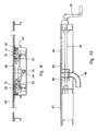
Fig. 2 is a longitudinal sectional view, according to the line 2-2 inFig. 1 ; -
Fig. 3 is a diagram showing several characteristics of the plate assembly inFig. 1 ; -
Fig. 4 is a longitudinal sectional view of a detail offigure 3 ; -
Fig. 5 is an enlarged detail, according to the section line 5-5 inFig. 1 , of the rear plate in combination with a sheet-clamping frame comprising a sheet clamping device according to the invention; -
Fig. 6 shows an enlarged detail according to the section line 6-6 inFig. 1 , in combination with a sheet-clamping frame comprising a sheet clamping device according to the invention; -
Fig. 7 is a view according to line 7-7 inFig. 6 ; -
Fig. 8 is a top view of the mould support table, according to the present invention; -
Fig. 9 is a longitudinal sectional view according to line 9-9 inFig. 8 ; -
Fig. 10 is a cross-sectional view according to line 10-10 inFig. 8 . -
Fig. 1 shows a perspective view, whileFig. 2 shows a sectional view of abox 10 for housing a mould support table, which forms part of a work station for thermoforming sheets of thermoplastic material, wherein thehousing box 10 is provided with acovering plate assembly 11 according to the present invention suitable to provide an opening of anadjustable reduction window 12 for supporting sheets of thermoformable plastic material of various sizes. - As shown in
figure 1 , thewindow 12 comprises front and rear edges which extend parallel to a longitudinal direction of thewindow 12, and two cross edges which extend at a right-angled direction to said front and rear edges. - The
plate assembly 11 comprises a firststeady bar member 14 which extends parallel to the front edge of thewindow 12, first andsecond side plates front bar member 14 and arear plate 15 slidably supported in the cross direction of thewindow 12, saidrear plate 15 being arranged in a parallel plane lying above the sliding plane of the twoslide plates - The three
mobile plates steady bar member 14 generally define the peripheral edges of a rectangular opening of thewindow 12, which by a controlled sliding movement of the same plates can be changed between a maximum opening shown by thereference number 12 inFig. 1 , and a minimum opening shown with a dotted line and by the reference number 12', keeping a steady position of thefront bar member 14 defining the front edge of thewindow 12. - Accordingly,
Fig. 1 shows a first distinguishing characteristic of the plate assembly according to the present invention; while with conventional plate systems in which all the plates are sliding along the four sides of the window, the space between the front side of thebox 10, or operator side, and the longitudinal front edge of thewindow 12, changes as the size of the window is changed, by the plate assembly according to the invention the space between the front side of thebox 10 and the longitudinal front edge of thewindow 12 remains always unchanged, equal to the minimum width of the frontsteady bar member 14, independently of the window size. In addition, as the size of thewindow 12 is reduced due to the forward sliding movement of the rear plate, as indicated by the dotted line 15', the rear longitudinal edge progressively moves close to the front edge of the window as defined by thesteady bar member 14, while maintaining the highest ergonomic working condition for an operator. - The
rear plate 15 is slidably supported alongtransversal guides 16, whereas the twoside plates front bar member 14, coplanar thereto, such as shown in detail inFig. 6 . As the guides of the threeplates - As stated above, the cross edges of the
window 12 are defined by theside plates front bar member 14, whereas the rear longitudinal edge is defined by a second bar member which may consist of at least one or more bar sections removably fastened to therear plate 15; according to the example shown, the rear bar member comprises threebar sections rear plate 15, coplanar to theside plates front bar member 14. - Particularly, as shown in
Fig. 1 to 4 , unlike the frontsteady bar member 14, the rear bar member consists of three axially-aligned bar sections, which are removably and/or replaceably connected to the fore edge of therear plate 15; more precisely, the rear bar comprises acentral bar section 17 and twoside bar sections 18, in which theside bar sections 18 can be slidably engaged with guide slots provided in theplates - More precisely, as shown in
Fig. 3 and 4 , the threebar sections pins 19 which are screwed in corresponding holes longitudinally spaced apart from each other by a same pitch; eachpin 19 is provided with ahead 20,Fig. 4 , which is configured to be engaged into a downwards openedlongitudinal slot 21, having a T shaped cross section at the fore edge of therear plate 15. - Two short downwards opened
cross slots 22 having the same pitch as thepins 20 extend from thelongitudinal slot 21 to the fore edge of therear plate 15, in order to allow for the introduction of thepins 19 and a subsequent sliding movement of the latter along theslot 21. - As schematically shown in
Fig. 3 , the connection of the threebar sections rear plate 15, can be carried out by firstly assembling theside plates rear plate 15 in a maximum spaced apart condition; accordingly, after therear plate 15 has been positioned as close to thefront bar member 14 as possible, in an easy access condition for an operator, one of the twoside bar sections 18 is first assembled in the central position shown in C, by fitting theheads 20 of thelocking pins 19 in the twocross slots 22, thepins 19 are then caused to laterally slide along theslot 21 until the firstside bar section 18 has been positioned at one end. Next, in the same manner, the secondside bar section 18 is assembled at the other end of therear plate 15; thecentral bar section 17 is then connected to thecross slots 22; at this stage, when the twoside plates bar sections rear plate 15. - To this purpose, as shown in
Fig. 4 , thecentral bar section 17 is configured with alongitudinal slot 23 of rectangular cross section; the twoside bar sections 18 have, in turn, at each end thereof, a key 24 of rectangular cross section, one of which is intended to penetrate into theslot 23 at one side of thecentral bar section 17, while theother key 24 is intended to penetrate and slide within acorresponding guide slot 25 which extends along the edge of thecorresponding side plate - The
side plates front bar member 14 and therear bar sections seal 26,Fig. 5 and 6 , to seal against a sheet of plastic material to be thermoformed. - Preferably, the three
bar sections side plates front bar member 14. Thereby, no subsequent mechanical processing is required; in addition, both the upper, and the bottom surfaces of the two side plates and of the two bar members are laying in respective upper and lower horizontal planes. - This solution proves to be extremely advantageous, not only because the three
bar sections rear plate 15 has been moved close to the operator side, but because the size of the threebar sections window 12 as required for the thermoforming plastic sheets of various sizes; accordingly, for variously-sized sheets only thecentral bar section 17 needs to be replaced with another one having a different length, or as an alternative, everybar section - While it is generally possible to arrange
bar sections side bar sections 18 having a prefixed length, independently of the longitudinal size of thewindow 12, and each time make use of acentral bar section 17 of a length suitable to the size of the sheets to be thermoformed; thereby, the fitting and adjustment operations of thewindow 12 are extremely simplified, without having to remove and replace the whole plate assembly, while maintaining the general features of the reduction window of the present invention, as previously stated, the rear bar member may consist of at least one bar section, or of two or more axially aligned bar sections extending between theside plates rear plate 15. -
Fig. 5, 6 and 7 show a further feature of the plate assembly according to the invention, in combination with a sheet-clamping frame 30 of a thermoforming station, in order to sealably press a plastic sheet to be thermoformed against sealinggaskets 16 arranged along the peripheral edges of thewindow 12. - As is well-known, in machines or thermoforming plants, suitable automatic systems are required for loading individual plastic sheets and removing the thermoformed articles.
- Accordingly, the sheet-clamping
frame 30 is provided with automated clamping members, at the frontsteady bar member 14 and the two side bar sections18 of therear plate 15. -
Fig. 5 shows a possible solution for bothside bar sections 18, whileFig. 6 shows an identical solution for thefront bar member 14. Particularly, as shown inFig. 5 , the sheet-clampingframe 30, the size thereof must correspond to the size of the adjustedreduction window 12 formed by the plate assembly, at a recessed orlongitudinal cavity 31 on the upper side of each of the twoside bar sections 18, comprises apivotable clamping member 32 configured with abottom lifting finger 33, which clampingmember 32 is connected to arotational shaft 34 extending along a rear side of theframe 30. Theshaft 34 is operatively connected to anactuator 35, for example a pneumatic cylinder or other actuator type, by alever 36 provided with alongitudinal slot 37 in which apin 39 of a rod of theactuator 35 is slidably engaged. - Therefore, by the
actuator 35, the clampingmember 32 can be angularly rotated between a rearward position, in which thefinger 33 protrudes into thecavity 31 in a spaced-apart position relative to an edge of a plastic sheet, and a forward position wherein thefinger 33 is arranged below the edge of said sheet. - A similar clamping member is shown in
Fig. 6 on a side of thefront bar member 14, the same reference numbers being used as inFig. 5 to designate similar or equivalent parts. - Thereby, by simultaneously operating the four clamping
members 32 on the front and rear sides of the sheet-clampingframe 30, a plate can be hold by theframe 30 during the up and/or down movements of the same sheet-clampingframe 30. - The solution proposed herein results to be extremely advantageous in that the thus-configured clamping system does not require any intervention or modification by a user, as the position of the
cavities 31 for the clamping fingers, relative to thefront bar member 14 and the twoside bar sections 18 of therear plate 15, does not change as the size of thewindow 12 and sheet-clampingframe 30 is changed. -
Fig. 2 ,8 ,9 and 10 show a further characteristic of the invention, consequent to the above-described plate assembly, and the combined use of the latter with an adjustable table for supporting amould 40 in a thermoforming station. - As discussed above, one of the characteristics which are distinguishing the plate assembly according to the invention from previously known or currently used plate assemblies, is that the front edge defined by the
front bar member 14 is maintained steady as the size of thewindow 12 is changed, as a result of the sliding movement of theside plates rear plate 15. Accordingly, as the size and position of thewindow 12 are changed, the position of themould 40 and of the air suction duct for the vacuum required to thermoforming, and/or for feeding the pressurized air suitable for providing an initial pre-stretching bubble for the plate of thermoplastic material are also changed. - In
Fig. 2 , accordingly, with the reference number 41 a support device for athermoforming mould 40 has been designated, which can be raised and lowered for example by control cylinders, not shown, to push abase plate 42 of themould 40, sealably against the bottom surfaces of thefront bar member 14, of theside plates bar sections - As shown in
Fig. 8 and9 , thesupport device 41 comprises a mould support table 43 configured with arectangular opening 44 extending to the front edge; at theopening 44, the table 43 comprises aslide 45 to which aduct 46 is fastened which can be connected to an air suction source and/or to a pressured air source, respectively connectable to a corresponding mould duct. - In order that the
duct 46 can always axially coincide with themould duct 41, independently of the position of the same mould on the support table 43, theslide 45 is movably supported in the cross direction of thewindow 12, between a rear position corresponding to awindow 12 of the maximum size, and a completely fore position close to the operator side, as shown in dotted lines, which corresponds to awindow 12 of minimum size. Theslide 45 move along two side guides 47 which are fastened to a respective intermediate section 43' of the mould support table 43. - The movement in the cross direction of the
slide 45, along theguides 47, can be controlled in any suitable manner; for example, in the case ofFigs. 8 and9 , the control of theslide 45 is obtained by means of a screw/nutscrew mechanical drive, which can be manually actuated; internally threadedbushings 48 are engaged with two threadedshafts 49 which are operatively connected to each other to rotate in a same direction, for example by achain transmission 50; one of the twoshafts 49, for example the left shaft inFig. 8 , is connected to a crank 50 that can be manually actuated or to any control actuator. - The
slide 45 is also provided with a device for locking themould base plate 42; the locking device comprises for example twopins 51 having asquare head 52 suitable to penetrate and be anchored within a matching hole on the bottom side of themould base 42, by a simple angular rotation. Accordingly, the twopins 51 are connected by a pair of gears and crank 53, to a control actuator, for example to the stem and respectively to the body of apneumatic cylinder 54. - From what has been said and shown above, it should be understood that a mobile plate assembly has been provided for a reduction window of a thermoforming station, characterized by two side plates, coplanar to a front steady bar, and by a third rear plate provided with one or more removably connectable bar sections, which define coplanar peripheral edge surfaces of an adjustable window for supporting plates of plastic material of different sizes to be thermoformed.
- Also according to the invention, a plate assembly has been provided as discussed above, in combination with a sheet-clamping frame provided with clamping members for the plates to be thermoformed, as well as a covering plate assembly for closing a mould housing box in a thermoforming station, in combination with a mobile support table for moulds of different sizes, which can be variously positioned on a support table provided with an adjustment device of air suction and/or pressurized air supply ducts.
- The proposed solution results to be extremely advantageous in terms of constructional simplicity, reliability, low cost, mechanical resistance, as it results to be compatible with the existing thermoforming stations, and with all manufacturing requirements.
- The rear plate, as described above, can be in an upper or lower position relative to the side plates, by changing in this latter case the position of the rear bar member, which would maintain all the characteristics and advantages obtainable with the present invention.
- Accordingly, other modifications and/or variations may be carried out to the plate assembly or a combination thereof with a sheet-clamping frame and/or with a mould support table of a thermoforming station, without departing from the claims.
Claims (11)
- A mobile-plate assembly suitable to form an adjustable window (12) for supporting sheets of thermoformable plastic material in a thermoforming station, in which the window (12) comprises a front edge, at an operator side, and a rear edge which extend parallel in a longitudinal direction; and
two cross edges which extend in a right-angled direction to the previous one, further including:first front steady bar member (14) which extends parallel to the front edge of the window (12);first (13A) and second (13B) side plates, said side plates (13A, 13B) being slidably supported in the longitudinal direction of the window (12), coplanar to the first front steady bar member (14); anda rear plate (15) slidably supported in the cross direction, on a plane parallel to the side plates (13A, 13B), in which the rear plate (15) is provided with a rear bar member (17, 18) which extends parallel to the rear edge of the window (12) andwhich is removably connected to the rear plate (15), CHARACTERISED IN THAT said rear bar member (17, 18) with the front bar member (14) and the side plates (13A, 13B) define coplanar peripheral edge surfaces of said adjustable window (12). - The mobile-plate assembly according to claim 1, characterised in that the rear bar member (17, 18) comprises at least one bar section extending between the side plates (13A, 13B).
- The mobile-plate assembly according to claim 2, characterised in that the rear bar section (17, 18) comprises a central bar section (17) and two side bar section axially aligned to the central bar section (13) of the rear plate (15).
- The mobile-plate assembly according to claim 3, characterised in that the side bar sections (18) are sliding along a longitudinal slot (21) of the rear plate (15), and in cross guide slots (25) along an edge of the side plates (13A, 13B).
- The mobile-plate assembly according to claim 3, characterised in that the central bar section (17) and/or side bar sections (18), are replaceable with bar sections (17, 18) of different dimensions.
- The mobile-plate assembly according to claim 4, characterised in that said bar sections (17, 18) are conformed with a groove and tongue joint.
- The mobile-plate assembly according to claim 1, characterised in that the rear plate (15) is sliding from a totally backward position, to a totally forward position in respect to the front bar member (14).
- The mobile-plate assembly according to any one of claims 1 to 7, in combination with a sheet-clamping frame (30) positioned above, characterised in that the front bar member (14) and the rear bar member (17, 18) has an upper longitudinal cavity (31), and in that the sheet-clamping frame (30), in positions corresponding to said cavities (31) of the front bar member (14), and said rear bar member (17, 18) comprises rotatable lifting members (33) for the sheets in plastic material to be thermoformed, which extend into said cavity (31), and control means (35) to angularly rotate said lifting members (33) between a backward disengagement position and a forward engagement position in respect to an edge of thermoformable plastic sheet.
- The mobile-plate assembly according to any one of claims 1 to 8, in combination with a mould support table (43) positioned underneath the plate assembly (13A, 13B, 15), characterised by comprising a locking system (51, 54) for the attachment of a mould (40), and a duct (46) for connection of the mould (40) to an air suction source and/or to a pressured air source, provided on a slide (45) movably supported by the mould support table (43) in a cross direction to the plate assembly, parallely to the rear plate (15).
- The mobile-plate assembly according to claim 9, characterised in that the mould support table (43) is housed in a vacuum-sealed box (10).
- The mobile-plate assembly according to claims 9 and/or 8, in which the mould support table (43) is vertically mobile between a lower position and an upper position against the mobile plate assembly (13A, 13B, 15), characterised in that the bottom surfaces of the side plates (13A, 13B), respectively of the front steady bar member (14), and the rear bar member (17, 18) of the rear plate (15) are defining a bearing and sealing surface for the mould support table (43) in the upper position of the mould (40).
Priority Applications (1)
| Application Number | Priority Date | Filing Date | Title |
|---|---|---|---|
| PL11194507T PL2465664T3 (en) | 2010-12-20 | 2011-12-20 | Mobile-plate assembly for a thermoforming station |
Applications Claiming Priority (1)
| Application Number | Priority Date | Filing Date | Title |
|---|---|---|---|
| ITMI2010A002323A IT1403271B1 (en) | 2010-12-20 | 2010-12-20 | MOBILE PLATE SYSTEM FOR A THERMOFORMING STATION |
Publications (2)
| Publication Number | Publication Date |
|---|---|
| EP2465664A1 EP2465664A1 (en) | 2012-06-20 |
| EP2465664B1 true EP2465664B1 (en) | 2013-11-13 |
Family
ID=43736978
Family Applications (1)
| Application Number | Title | Priority Date | Filing Date |
|---|---|---|---|
| EP11194507.7A Not-in-force EP2465664B1 (en) | 2010-12-20 | 2011-12-20 | Mobile-plate assembly for a thermoforming station |
Country Status (3)
| Country | Link |
|---|---|
| EP (1) | EP2465664B1 (en) |
| IT (1) | IT1403271B1 (en) |
| PL (1) | PL2465664T3 (en) |
Cited By (2)
| Publication number | Priority date | Publication date | Assignee | Title |
|---|---|---|---|---|
| EP3470204A1 (en) | 2017-10-13 | 2019-04-17 | Cannon Ergos S.p.A. | Adjustable dimensional frame for a thermoforming machine and adjustment method |
| PL446269A1 (en) * | 2023-09-29 | 2025-03-31 | Tools Factory Spółka Jawna Agnieszka Popławska, Robert Popławski | Thermoforming station of a thermoforming machine |
Families Citing this family (1)
| Publication number | Priority date | Publication date | Assignee | Title |
|---|---|---|---|---|
| TR201712347A2 (en) * | 2017-08-18 | 2017-09-21 | Chs Plastik Makina Ambalaj Vakum San Tic Ltd Sti | A DRIVE MECHANISM |
Family Cites Families (4)
| Publication number | Priority date | Publication date | Assignee | Title |
|---|---|---|---|---|
| US5167969A (en) * | 1991-04-09 | 1992-12-01 | Demaio Jr Joseph T | Split frame for rotary vacuum mold unit |
| DE4424845C3 (en) * | 1994-07-14 | 2000-01-05 | Georg Geis Maschinenfabrik | Cover plate for vacuum molding machines |
| DE19723561C2 (en) * | 1997-06-05 | 2002-06-27 | Illig Maschinenbau Adolf | Adjustable clamping frame for the molding station of a thermoforming machine |
| ITMI20061327A1 (en) | 2006-07-07 | 2008-01-08 | Forma Srl | TELESCOPIC ADJUSTABLE COVERING DEVICE FOR THERMOFURGEOUS MACHINES |
-
2010
- 2010-12-20 IT ITMI2010A002323A patent/IT1403271B1/en active
-
2011
- 2011-12-20 EP EP11194507.7A patent/EP2465664B1/en not_active Not-in-force
- 2011-12-20 PL PL11194507T patent/PL2465664T3/en unknown
Cited By (2)
| Publication number | Priority date | Publication date | Assignee | Title |
|---|---|---|---|---|
| EP3470204A1 (en) | 2017-10-13 | 2019-04-17 | Cannon Ergos S.p.A. | Adjustable dimensional frame for a thermoforming machine and adjustment method |
| PL446269A1 (en) * | 2023-09-29 | 2025-03-31 | Tools Factory Spółka Jawna Agnieszka Popławska, Robert Popławski | Thermoforming station of a thermoforming machine |
Also Published As
| Publication number | Publication date |
|---|---|
| ITMI20102323A1 (en) | 2012-06-21 |
| PL2465664T3 (en) | 2014-10-31 |
| EP2465664A1 (en) | 2012-06-20 |
| IT1403271B1 (en) | 2013-10-17 |
Similar Documents
| Publication | Publication Date | Title |
|---|---|---|
| EP3647004B1 (en) | Cutting machine to cut panels made of wood or the like | |
| CN205343337U (en) | Plank processing equipment with locate function | |
| EP2465664B1 (en) | Mobile-plate assembly for a thermoforming station | |
| WO2021218257A1 (en) | Machining method of automatic edge banding machine | |
| EP2990147B1 (en) | Machine for cutting wood panels or the like | |
| CN106313452B (en) | An unmanned cover plate production system | |
| CA2181644A1 (en) | Apparatus for machine cutting of tubes | |
| EP4353423A1 (en) | Robotic machine and handling device | |
| CN211136237U (en) | Automatic processing equipment for door and window materials | |
| EP3639994B1 (en) | Cutting machine to cut panels made of wood or the like | |
| US5794481A (en) | Device for bending or curving hollow-section strips | |
| EP3639957B1 (en) | Cutting machine to cut panels made of wood or the like | |
| CN201380312Y (en) | Duplex head milling machine for processing sole die chamfering | |
| CN216139108U (en) | Chamfering cutting mechanism and chamfering machine for special-shaped plates | |
| EP2075104A2 (en) | Edge bander for panels with an apparatus for machining edges | |
| US4243084A (en) | Door sizing machine | |
| KR100414954B1 (en) | Length adjustable moving mold | |
| CN111070276B (en) | Automatic fine cutting control system | |
| JP2000153502A (en) | Mortising machine for wooden building | |
| CN208277463U (en) | A kind of combined cap displacement closing lid machine | |
| EP3533571B1 (en) | A machine for cutting panels made of wood or the like | |
| CN222403659U (en) | Cutting device for profile composite processing | |
| EP2127831B1 (en) | Machine tool comprising a guiding apparatus | |
| US9126254B2 (en) | Apparatus for the application of spacer elements onto plates | |
| CN214870964U (en) | Numerical control guillootine for PET membrane is cut in PCB processing |
Legal Events
| Date | Code | Title | Description |
|---|---|---|---|
| PUAI | Public reference made under article 153(3) epc to a published international application that has entered the european phase |
Free format text: ORIGINAL CODE: 0009012 |
|
| AK | Designated contracting states |
Kind code of ref document: A1 Designated state(s): AL AT BE BG CH CY CZ DE DK EE ES FI FR GB GR HR HU IE IS IT LI LT LU LV MC MK MT NL NO PL PT RO RS SE SI SK SM TR |
|
| AX | Request for extension of the european patent |
Extension state: BA ME |
|
| 17P | Request for examination filed |
Effective date: 20121211 |
|
| GRAP | Despatch of communication of intention to grant a patent |
Free format text: ORIGINAL CODE: EPIDOSNIGR1 |
|
| RIC1 | Information provided on ipc code assigned before grant |
Ipc: B29C 51/26 20060101AFI20130508BHEP Ipc: B29C 51/08 20060101ALN20130508BHEP |
|
| INTG | Intention to grant announced |
Effective date: 20130524 |
|
| GRAS | Grant fee paid |
Free format text: ORIGINAL CODE: EPIDOSNIGR3 |
|
| GRAA | (expected) grant |
Free format text: ORIGINAL CODE: 0009210 |
|
| AK | Designated contracting states |
Kind code of ref document: B1 Designated state(s): AL AT BE BG CH CY CZ DE DK EE ES FI FR GB GR HR HU IE IS IT LI LT LU LV MC MK MT NL NO PL PT RO RS SE SI SK SM TR |
|
| REG | Reference to a national code |
Ref country code: GB Ref legal event code: FG4D |
|
| REG | Reference to a national code |
Ref country code: CH Ref legal event code: EP |
|
| REG | Reference to a national code |
Ref country code: AT Ref legal event code: REF Ref document number: 640375 Country of ref document: AT Kind code of ref document: T Effective date: 20131215 |
|
| REG | Reference to a national code |
Ref country code: IE Ref legal event code: FG4D |
|
| REG | Reference to a national code |
Ref country code: DE Ref legal event code: R096 Ref document number: 602011003701 Country of ref document: DE Effective date: 20140109 |
|
| RAP2 | Party data changed (patent owner data changed or rights of a patent transferred) |
Owner name: CANNON ERGOS S.P.A. |
|
| REG | Reference to a national code |
Ref country code: NL Ref legal event code: VDEP Effective date: 20131113 |
|
| REG | Reference to a national code |
Ref country code: AT Ref legal event code: MK05 Ref document number: 640375 Country of ref document: AT Kind code of ref document: T Effective date: 20131113 |
|
| REG | Reference to a national code |
Ref country code: LT Ref legal event code: MG4D |
|
| PG25 | Lapsed in a contracting state [announced via postgrant information from national office to epo] |
Ref country code: FI Free format text: LAPSE BECAUSE OF FAILURE TO SUBMIT A TRANSLATION OF THE DESCRIPTION OR TO PAY THE FEE WITHIN THE PRESCRIBED TIME-LIMIT Effective date: 20131113 Ref country code: HR Free format text: LAPSE BECAUSE OF FAILURE TO SUBMIT A TRANSLATION OF THE DESCRIPTION OR TO PAY THE FEE WITHIN THE PRESCRIBED TIME-LIMIT Effective date: 20131113 Ref country code: IS Free format text: LAPSE BECAUSE OF FAILURE TO SUBMIT A TRANSLATION OF THE DESCRIPTION OR TO PAY THE FEE WITHIN THE PRESCRIBED TIME-LIMIT Effective date: 20140313 Ref country code: NO Free format text: LAPSE BECAUSE OF FAILURE TO SUBMIT A TRANSLATION OF THE DESCRIPTION OR TO PAY THE FEE WITHIN THE PRESCRIBED TIME-LIMIT Effective date: 20140213 Ref country code: SE Free format text: LAPSE BECAUSE OF FAILURE TO SUBMIT A TRANSLATION OF THE DESCRIPTION OR TO PAY THE FEE WITHIN THE PRESCRIBED TIME-LIMIT Effective date: 20131113 Ref country code: NL Free format text: LAPSE BECAUSE OF FAILURE TO SUBMIT A TRANSLATION OF THE DESCRIPTION OR TO PAY THE FEE WITHIN THE PRESCRIBED TIME-LIMIT Effective date: 20131113 Ref country code: LT Free format text: LAPSE BECAUSE OF FAILURE TO SUBMIT A TRANSLATION OF THE DESCRIPTION OR TO PAY THE FEE WITHIN THE PRESCRIBED TIME-LIMIT Effective date: 20131113 |
|
| PG25 | Lapsed in a contracting state [announced via postgrant information from national office to epo] |
Ref country code: AT Free format text: LAPSE BECAUSE OF FAILURE TO SUBMIT A TRANSLATION OF THE DESCRIPTION OR TO PAY THE FEE WITHIN THE PRESCRIBED TIME-LIMIT Effective date: 20131113 Ref country code: ES Free format text: LAPSE BECAUSE OF FAILURE TO SUBMIT A TRANSLATION OF THE DESCRIPTION OR TO PAY THE FEE WITHIN THE PRESCRIBED TIME-LIMIT Effective date: 20131113 Ref country code: CY Free format text: LAPSE BECAUSE OF FAILURE TO SUBMIT A TRANSLATION OF THE DESCRIPTION OR TO PAY THE FEE WITHIN THE PRESCRIBED TIME-LIMIT Effective date: 20131113 Ref country code: RS Free format text: LAPSE BECAUSE OF FAILURE TO SUBMIT A TRANSLATION OF THE DESCRIPTION OR TO PAY THE FEE WITHIN THE PRESCRIBED TIME-LIMIT Effective date: 20131113 Ref country code: LV Free format text: LAPSE BECAUSE OF FAILURE TO SUBMIT A TRANSLATION OF THE DESCRIPTION OR TO PAY THE FEE WITHIN THE PRESCRIBED TIME-LIMIT Effective date: 20131113 Ref country code: BE Free format text: LAPSE BECAUSE OF FAILURE TO SUBMIT A TRANSLATION OF THE DESCRIPTION OR TO PAY THE FEE WITHIN THE PRESCRIBED TIME-LIMIT Effective date: 20131113 |
|
| PG25 | Lapsed in a contracting state [announced via postgrant information from national office to epo] |
Ref country code: PT Free format text: LAPSE BECAUSE OF FAILURE TO SUBMIT A TRANSLATION OF THE DESCRIPTION OR TO PAY THE FEE WITHIN THE PRESCRIBED TIME-LIMIT Effective date: 20140313 |
|
| PG25 | Lapsed in a contracting state [announced via postgrant information from national office to epo] |
Ref country code: EE Free format text: LAPSE BECAUSE OF FAILURE TO SUBMIT A TRANSLATION OF THE DESCRIPTION OR TO PAY THE FEE WITHIN THE PRESCRIBED TIME-LIMIT Effective date: 20131113 |
|
| REG | Reference to a national code |
Ref country code: DE Ref legal event code: R097 Ref document number: 602011003701 Country of ref document: DE |
|
| PG25 | Lapsed in a contracting state [announced via postgrant information from national office to epo] |
Ref country code: SK Free format text: LAPSE BECAUSE OF FAILURE TO SUBMIT A TRANSLATION OF THE DESCRIPTION OR TO PAY THE FEE WITHIN THE PRESCRIBED TIME-LIMIT Effective date: 20131113 Ref country code: CZ Free format text: LAPSE BECAUSE OF FAILURE TO SUBMIT A TRANSLATION OF THE DESCRIPTION OR TO PAY THE FEE WITHIN THE PRESCRIBED TIME-LIMIT Effective date: 20131113 Ref country code: RO Free format text: LAPSE BECAUSE OF FAILURE TO SUBMIT A TRANSLATION OF THE DESCRIPTION OR TO PAY THE FEE WITHIN THE PRESCRIBED TIME-LIMIT Effective date: 20131113 |
|
| PLBE | No opposition filed within time limit |
Free format text: ORIGINAL CODE: 0009261 |
|
| STAA | Information on the status of an ep patent application or granted ep patent |
Free format text: STATUS: NO OPPOSITION FILED WITHIN TIME LIMIT |
|
| REG | Reference to a national code |
Ref country code: IE Ref legal event code: MM4A |
|
| PG25 | Lapsed in a contracting state [announced via postgrant information from national office to epo] |
Ref country code: DK Free format text: LAPSE BECAUSE OF FAILURE TO SUBMIT A TRANSLATION OF THE DESCRIPTION OR TO PAY THE FEE WITHIN THE PRESCRIBED TIME-LIMIT Effective date: 20131113 |
|
| 26N | No opposition filed |
Effective date: 20140814 |
|
| PG25 | Lapsed in a contracting state [announced via postgrant information from national office to epo] |
Ref country code: IE Free format text: LAPSE BECAUSE OF NON-PAYMENT OF DUE FEES Effective date: 20131220 |
|
| REG | Reference to a national code |
Ref country code: PL Ref legal event code: T3 |
|
| REG | Reference to a national code |
Ref country code: DE Ref legal event code: R097 Ref document number: 602011003701 Country of ref document: DE Effective date: 20140814 |
|
| PG25 | Lapsed in a contracting state [announced via postgrant information from national office to epo] |
Ref country code: SI Free format text: LAPSE BECAUSE OF FAILURE TO SUBMIT A TRANSLATION OF THE DESCRIPTION OR TO PAY THE FEE WITHIN THE PRESCRIBED TIME-LIMIT Effective date: 20131113 |
|
| PG25 | Lapsed in a contracting state [announced via postgrant information from national office to epo] |
Ref country code: MC Free format text: LAPSE BECAUSE OF FAILURE TO SUBMIT A TRANSLATION OF THE DESCRIPTION OR TO PAY THE FEE WITHIN THE PRESCRIBED TIME-LIMIT Effective date: 20131113 |
|
| PG25 | Lapsed in a contracting state [announced via postgrant information from national office to epo] |
Ref country code: SM Free format text: LAPSE BECAUSE OF FAILURE TO SUBMIT A TRANSLATION OF THE DESCRIPTION OR TO PAY THE FEE WITHIN THE PRESCRIBED TIME-LIMIT Effective date: 20131113 |
|
| PG25 | Lapsed in a contracting state [announced via postgrant information from national office to epo] |
Ref country code: BG Free format text: LAPSE BECAUSE OF FAILURE TO SUBMIT A TRANSLATION OF THE DESCRIPTION OR TO PAY THE FEE WITHIN THE PRESCRIBED TIME-LIMIT Effective date: 20131113 Ref country code: HU Free format text: LAPSE BECAUSE OF FAILURE TO SUBMIT A TRANSLATION OF THE DESCRIPTION OR TO PAY THE FEE WITHIN THE PRESCRIBED TIME-LIMIT; INVALID AB INITIO Effective date: 20111220 Ref country code: MK Free format text: LAPSE BECAUSE OF FAILURE TO SUBMIT A TRANSLATION OF THE DESCRIPTION OR TO PAY THE FEE WITHIN THE PRESCRIBED TIME-LIMIT Effective date: 20131113 Ref country code: LU Free format text: LAPSE BECAUSE OF NON-PAYMENT OF DUE FEES Effective date: 20131220 |
|
| REG | Reference to a national code |
Ref country code: CH Ref legal event code: PL |
|
| PG25 | Lapsed in a contracting state [announced via postgrant information from national office to epo] |
Ref country code: IT Free format text: LAPSE BECAUSE OF FAILURE TO SUBMIT A TRANSLATION OF THE DESCRIPTION OR TO PAY THE FEE WITHIN THE PRESCRIBED TIME-LIMIT Effective date: 20131113 Ref country code: MT Free format text: LAPSE BECAUSE OF FAILURE TO SUBMIT A TRANSLATION OF THE DESCRIPTION OR TO PAY THE FEE WITHIN THE PRESCRIBED TIME-LIMIT Effective date: 20131113 Ref country code: GR Free format text: LAPSE BECAUSE OF NON-PAYMENT OF DUE FEES Effective date: 20131113 |
|
| PG25 | Lapsed in a contracting state [announced via postgrant information from national office to epo] |
Ref country code: LI Free format text: LAPSE BECAUSE OF NON-PAYMENT OF DUE FEES Effective date: 20141231 Ref country code: CH Free format text: LAPSE BECAUSE OF NON-PAYMENT OF DUE FEES Effective date: 20141231 |
|
| REG | Reference to a national code |
Ref country code: FR Ref legal event code: PLFP Year of fee payment: 5 |
|
| PGFP | Annual fee paid to national office [announced via postgrant information from national office to epo] |
Ref country code: TR Payment date: 20160108 Year of fee payment: 6 |
|
| PG25 | Lapsed in a contracting state [announced via postgrant information from national office to epo] |
Ref country code: GR Free format text: LAPSE BECAUSE OF FAILURE TO SUBMIT A TRANSLATION OF THE DESCRIPTION OR TO PAY THE FEE WITHIN THE PRESCRIBED TIME-LIMIT Effective date: 20140214 |
|
| REG | Reference to a national code |
Ref country code: FR Ref legal event code: PLFP Year of fee payment: 6 |
|
| PGFP | Annual fee paid to national office [announced via postgrant information from national office to epo] |
Ref country code: FR Payment date: 20161123 Year of fee payment: 6 |
|
| REG | Reference to a national code |
Ref country code: FR Ref legal event code: ST Effective date: 20180831 |
|
| PG25 | Lapsed in a contracting state [announced via postgrant information from national office to epo] |
Ref country code: AL Free format text: LAPSE BECAUSE OF FAILURE TO SUBMIT A TRANSLATION OF THE DESCRIPTION OR TO PAY THE FEE WITHIN THE PRESCRIBED TIME-LIMIT Effective date: 20131113 Ref country code: FR Free format text: LAPSE BECAUSE OF NON-PAYMENT OF DUE FEES Effective date: 20180102 |
|
| PGFP | Annual fee paid to national office [announced via postgrant information from national office to epo] |
Ref country code: PL Payment date: 20181207 Year of fee payment: 8 |
|
| PGFP | Annual fee paid to national office [announced via postgrant information from national office to epo] |
Ref country code: GB Payment date: 20200102 Year of fee payment: 9 |
|
| GBPC | Gb: european patent ceased through non-payment of renewal fee |
Effective date: 20201220 |
|
| PG25 | Lapsed in a contracting state [announced via postgrant information from national office to epo] |
Ref country code: GB Free format text: LAPSE BECAUSE OF NON-PAYMENT OF DUE FEES Effective date: 20201220 |
|
| PGFP | Annual fee paid to national office [announced via postgrant information from national office to epo] |
Ref country code: DE Payment date: 20211227 Year of fee payment: 11 |
|
| PG25 | Lapsed in a contracting state [announced via postgrant information from national office to epo] |
Ref country code: PL Free format text: LAPSE BECAUSE OF NON-PAYMENT OF DUE FEES Effective date: 20191220 |
|
| PG25 | Lapsed in a contracting state [announced via postgrant information from national office to epo] |
Ref country code: TR Free format text: LAPSE BECAUSE OF NON-PAYMENT OF DUE FEES Effective date: 20171220 |
|
| REG | Reference to a national code |
Ref country code: DE Ref legal event code: R119 Ref document number: 602011003701 Country of ref document: DE |
|
| PG25 | Lapsed in a contracting state [announced via postgrant information from national office to epo] |
Ref country code: DE Free format text: LAPSE BECAUSE OF NON-PAYMENT OF DUE FEES Effective date: 20230701 |