EP2463988A2 - Electric motor - Google Patents
Electric motor Download PDFInfo
- Publication number
- EP2463988A2 EP2463988A2 EP11189243A EP11189243A EP2463988A2 EP 2463988 A2 EP2463988 A2 EP 2463988A2 EP 11189243 A EP11189243 A EP 11189243A EP 11189243 A EP11189243 A EP 11189243A EP 2463988 A2 EP2463988 A2 EP 2463988A2
- Authority
- EP
- European Patent Office
- Prior art keywords
- gap length
- circumferential part
- rotor core
- stator core
- outer circumferential
- Prior art date
- Legal status (The legal status is an assumption and is not a legal conclusion. Google has not performed a legal analysis and makes no representation as to the accuracy of the status listed.)
- Withdrawn
Links
Images







Classifications
-
- H—ELECTRICITY
- H02—GENERATION; CONVERSION OR DISTRIBUTION OF ELECTRIC POWER
- H02K—DYNAMO-ELECTRIC MACHINES
- H02K1/00—Details of the magnetic circuit
- H02K1/06—Details of the magnetic circuit characterised by the shape, form or construction
- H02K1/22—Rotating parts of the magnetic circuit
- H02K1/27—Rotor cores with permanent magnets
- H02K1/2706—Inner rotors
- H02K1/272—Inner rotors the magnetisation axis of the magnets being perpendicular to the rotor axis
- H02K1/274—Inner rotors the magnetisation axis of the magnets being perpendicular to the rotor axis the rotor consisting of two or more circumferentially positioned magnets
- H02K1/2753—Inner rotors the magnetisation axis of the magnets being perpendicular to the rotor axis the rotor consisting of two or more circumferentially positioned magnets the rotor consisting of magnets or groups of magnets arranged with alternating polarity
- H02K1/276—Magnets embedded in the magnetic core, e.g. interior permanent magnets [IPM]
-
- H—ELECTRICITY
- H02—GENERATION; CONVERSION OR DISTRIBUTION OF ELECTRIC POWER
- H02K—DYNAMO-ELECTRIC MACHINES
- H02K1/00—Details of the magnetic circuit
- H02K1/04—Details of the magnetic circuit characterised by the material used for insulating the magnetic circuit or parts thereof
-
- H—ELECTRICITY
- H02—GENERATION; CONVERSION OR DISTRIBUTION OF ELECTRIC POWER
- H02K—DYNAMO-ELECTRIC MACHINES
- H02K1/00—Details of the magnetic circuit
- H02K1/06—Details of the magnetic circuit characterised by the shape, form or construction
-
- H—ELECTRICITY
- H02—GENERATION; CONVERSION OR DISTRIBUTION OF ELECTRIC POWER
- H02K—DYNAMO-ELECTRIC MACHINES
- H02K1/00—Details of the magnetic circuit
- H02K1/06—Details of the magnetic circuit characterised by the shape, form or construction
- H02K1/12—Stationary parts of the magnetic circuit
- H02K1/14—Stator cores with salient poles
- H02K1/146—Stator cores with salient poles consisting of a generally annular yoke with salient poles
-
- H—ELECTRICITY
- H02—GENERATION; CONVERSION OR DISTRIBUTION OF ELECTRIC POWER
- H02K—DYNAMO-ELECTRIC MACHINES
- H02K29/00—Motors or generators having non-mechanical commutating devices, e.g. discharge tubes or semiconductor devices
- H02K29/03—Motors or generators having non-mechanical commutating devices, e.g. discharge tubes or semiconductor devices with a magnetic circuit specially adapted for avoiding torque ripples or self-starting problems
-
- H—ELECTRICITY
- H02—GENERATION; CONVERSION OR DISTRIBUTION OF ELECTRIC POWER
- H02K—DYNAMO-ELECTRIC MACHINES
- H02K2201/00—Specific aspects not provided for in the other groups of this subclass relating to the magnetic circuits
- H02K2201/03—Machines characterised by aspects of the air-gap between rotor and stator
-
- H—ELECTRICITY
- H02—GENERATION; CONVERSION OR DISTRIBUTION OF ELECTRIC POWER
- H02K—DYNAMO-ELECTRIC MACHINES
- H02K2213/00—Specific aspects, not otherwise provided for and not covered by codes H02K2201/00 - H02K2211/00
- H02K2213/03—Machines characterised by numerical values, ranges, mathematical expressions or similar information
Definitions
- the present invention disclosed herein relates to an electric motor.
- the above publication discloses a permanent magnet type rotor of a permanent magnet type electric motor in which the permanent magnet is buried in the vicinity of the outer circumferential part of the rotor iron core (rotor core) .
- a stator iron core stator core
- stator core stator core
- magnetic flux density distribution between the outer circumferential part of the rotor iron core and an inner circumferential part of the stator iron core is made distribution close to a sinusoidal waveform.
- a waveform of inductive voltage can be brought close to a sinusoidal waveform, and cogging torque and pulsation of torque can be reduced, so that a performance of the electric motor can be improved.
- This invention is achieved in order to solve the problem as described above, and one object of this invention is to provide an electric motor capable of improving a performance of the electric motor more by bringing magnetic flux density distribution between a rotor core and a stator core closer to a sinusoidal waveform.
- an electric motor in one aspect of the present invention, includes a rotor core, a stator core provided so as to face the rotor core in the radial direction, and a permanent magnet buried in the vicinity of an outer circumferential part of the rotor core, wherein the outer circumferential part of the rotor core and an inner circumferential part of the stator core are formed in such a manner that a radial gap length between the outer circumferential part of the rotor core and the inner circumferential part of the stator core for one magnetic pole of the permanent magnet becomes a gap length along a gap length 1 regulated by the following expression (1) capable of making magnetic flux density distribution between the outer circumferential part of the rotor core and the inner circumferential part of the stator core a sinusoidal waveform.
- the reference sign x denotes a distance of a part of a circumference of a circle around a center of the rotor core passing between the outer circumferential part of the rotor core and the inner circumferential part of the stator core, the distance being measured from a center of the part corresponding to one magnetic pole of the permanent magnet along the circumference of the circle
- the reference sign 1 max denotes a maximum value of the gap length 1
- the reference sign 1 min denotes a minimum value of the gap length 1
- the reference sign ⁇ denotes a length of the part of the circumference of the circle around the center of the rotor core passing between the outer circumferential part of the rotor core and the inner circumferential part of the stator core, the part corresponding to one magnetic pole of the permanent magnet.
- the outer circumferential part of the rotor core and the inner circumferential part of the stator core are formed in such a manner that the radial gap length between the outer circumferential part of the rotor core and the inner circumferential part of the stator core for one magnetic pole of the permanent magnet becomes the gap length along the gap length 1 regulated by the above expression (1) capable of making the magnetic flux density distribution between the outer circumferential part of the rotor core and the inner circumferential part of the stator core a sinusoidal waveform.
- the magnetic flux density distribution between the outer circumferential part of the rotor core and the inner circumferential part of the stator core can be brought closer to a sinusoidal waveform based on the above expression (1) capable of making the magnetic flux density distribution between the outer circumferential part of the rotor core and the inner circumferential part of the stator core a sinusoidal waveform.
- the waveform of the inductive voltage can be brought closer to a sinusoidal waveform, and cogging torque and pulsation of torque can be more reduced, so that a performance of the electric motor can be more improved.
- the electric motor 100 is provided with a stator 1, a rotor 2, bearings 3, brackets 4, and a frame 5.
- the stator 1 and the rotor 2 are arranged inside the frame 5.
- the stator 1 and the rotor 2 are arranged so as to face each other in the radial direction of the rotor 2.
- the brackets 4 are respectively attached to both ends of the frame 5.
- the bearings 3 formed by ball bearings or the like are respectively attached to the brackets 4.
- a shaft 22 described later is provided in the rotor 2 so as to pass through the rotor 2.
- This shaft 22 is rotatably supported on a pair of shaft holes 4a provided in the brackets 4 respectively through the bearings 3.
- the stator 1 is formed by a stator core 11 in which nine slots 12 are formed, and wirings 13. These nine slots 12 are formed inside the stator core 11.
- the slots 12 are arranged at equal intervals along the rotation direction of a rotor core 21.
- the stator core 11 is provided so as to have a predetermined space (gap) to face the rotor core 21 of the rotor 2 described later in the radial direction.
- the stator core 11 is formed by laminating magnetic steel sheets for example.
- the wirings 13 are wound between the slots 12 by concentrated winding or distributed winding. It should be noted that a part of the stator core 11 between the two adjacent slots 12 forms a tooth portion 14. An outer circumferential part of the stator core 11 forms a yoke portion 15.
- the rotor 2 is formed by the rotor core 21, the shaft 22, and six permanent magnets 23.
- the rotor core 21 is formed by laminating magnetic steel sheets for example.
- the shaft 22 is provided so as to pass through a center of the rotor core 21.
- the six permanent magnets 23 are buried in the vicinity of an outer circumferential part of the rotor core 21.
- the six permanent magnets 23 are respectively buried (fitted) in six hole portions 24 formed in the vicinity of the outer circumferential part of the rotor core 21. It should be noted that these six permanent magnets 23 are arranged in such a manner that magnetic poles on the outer circumferential side (N pole, S pole) are alternately opposite one by one along the rotation direction.
- the permanent magnets 23 are arranged at equal intervals along the rotation direction of the rotor core 21. Magnetic flux generated from the permanent magnets 23 flow in the substantially radial direction in the space (gap) between the stator core 11 and the rotor core 21. Clearances 25 are provided in both ends of the permanent magnets 23 fitted in the hole portions 24 along the rotation direction of the rotor core 21.
- the outer circumferential part of the rotor core 21 is formed in such a manner that a radial gap length between the outer circumferential part of the rotor core 21 and an inner circumferential part of the stator core 11 for one magnetic pole of the permanent magnet 23 (length of the space (gap) between the rotor core 21 and the stator core 11) becomes a gap length along a gap length 1 regulated by the following expression (2) capable of making magnetic flux density distribution between the outer circumferential part of the rotor core 21 and the inner circumferential part of the stator core 11 a sinusoidal waveform.
- 3 and 4 indicates a shape of the outer circumferential part of the rotor core 21 in a case where the outer circumferential part of the rotor core 21 is formed in such a manner that the gap length between the rotor core 21 and the stator core 11 substantially matches with the gap length 1 regulated by the following expression (2) over the entire one magnetic pole of the permanent magnet 23 (theoretical shape) .
- the reference sign x denotes a distance of a part of a circumference of a circle C1 (see Figs. 3 and 4 ) around a center of the rotor core 21 passing between the outer circumferential part of the rotor core 21 and the inner circumferential part of the stator core 11, the distance being measured from a center of the part corresponding to one magnetic pole of the permanent magnet 23 along the circumference of the circle C1 (distance measured from a point O1 along an X1 axis in Figs. 3 and 4 ).
- the reference sign 1 max denotes a maximum value of the gap length 1 (see Fig.
- the reference sign 1 min denotes a minimum value of the gap length 1 (see Fig. 4 ).
- the reference sign ⁇ 1 denotes a length of the part of the circumference of the circle C1 corresponding to one magnetic pole of the permanent magnet 23 (see Fig. 3 ). A developing process for the above expression (2) will be described later.
- a portion ranging from a center part to one end of a part of the outer circumferential part of the rotor core 21, the part corresponding to one magnetic pole of the permanent magnet 23 is formed by two arc portions 26 and 27 (a first arc portion and a second arc portion (see Fig. 5 )) continuing to each other in such a manner that the gap length between the rotor core 21 and the stator core 11 becomes the gap length along the gap length 1 regulated by the above expression (2).
- the inner circumferential part of the stator core 11 is formed into a substantially perfect circle around the center 0 of the rotor core 21 (see Fig. 2 ).
- the arc portion 26 has a part (point P1) at which the gap length between the rotor core 21 and the stator core 11 is minimum, and is formed in such a manner that the gap length becomes a gap length substantially matching with the gap length 1 regulated by the above expression (2).
- the arc portion 27 has a part (point P2) at which the gap length between the rotor core 21 and the stator core 11 is maximum, and is formed in such a manner that the gap length becomes the gap length substantially matching with the gap length 1 regulated by the above expression (2).
- a center of the arc portion 26 and a center of the arc portion 27 are respectively set at positions displaced from the center O of the rotor core 21.
- a central coordinate (x1, y1) of the arc portion 26 in an XY orthogonal coordinate system taking the center O of the rotor core 21 as an origin is set within a range regulated by -0.1 R0 ⁇ x1 ⁇ 0.1 R0 and 0 ⁇ y1 ⁇ 0.7 R0.
- a central coordinate (x2, y2) of the arc portion 27 is set within a range regulated by -0.6 R0 ⁇ x2 ⁇ 0 and -0.6 R0 ⁇ y2 ⁇ 0.5 R0.
- the gap length between the rotor core 21 and the stator core 11 can be made the gap length along the gap length 1 regulated by the above expression (2) with using the arc portion 26 and the arc portion 27.
- the reference sign R0 denotes a radius of a circle C2 around the center of the rotor core 21 circumscribed about the rotor core 21.
- a radius R1 of the arc portion 26 is set to be smaller than the radius R0 of the circle C2.
- an angle ⁇ made by a Y axis and a straight line connecting the origin O and a point Q where the arc portion 26 and the arc portion 27 are connected is set within a range regulated by 0.45 ⁇ p ⁇ ⁇ ⁇ 0.55 ⁇ p.
- the reference sign ⁇ p denotes a center angle (60 degrees) of a part of the above circle C2 corresponding to one magnetic pole of the permanent magnet 23.
- Fig. 6 is an imagery view in which a stator core 11a and a rotor core 21a having the same configurations as the stator core 11 and the rotor core 21 according to the present embodiment are developed in a straight line.
- An X1 axis shown in Fig. 6 corresponds to the X1 axis shown in Figs. 3 and 4 .
- slots provided in the stator core 11a, hole portions in which permanent magnets 23a of the rotor core 21a are fitted, and the like are omitted.
- magnetic flux ⁇ generated from the permanent magnets 23a, the flux flowing through a predetermined position (position x) of a space (gap) between the rotor core 21a and the stator core 11a is indicated as a function ⁇ (x) of the position x.
- magnetic resistance R and the gap length 1 at the predetermined position (position x) of the space (gap) between the rotor core 21a and the stator core 11a are respectively indicated as functions R(x) and 1(x) of the position x.
- a magnetic circuit 50 to cope with the magnetic flux ⁇ (x) generated from an N pole to an S pole between the two adjacent permanent magnets 23a will be supposed.
- the magnetic flux ⁇ (x) passing inside the magnetic circuit 50 supposed as above, and the magnetic resistance R(x) of the magnetic circuit 50 are respectively expressed by the following expressions (3) and (4). Magnetic resistance in a part other than the gap will be ignored.
- the reference sign F denotes magnetomotive force of the permanent magnets 23a
- the reference sign ⁇ denotes a magnetic resistance rate of the space (gap) between the rotor core 21a and the stator core 11a
- the reference sign ⁇ S denotes a cross sectional area of the magnetic circuit 50.
- the above expression (6) is rewritten based on the constants A and B determined in such a way, the above expression (2) is obtained.
- a graph with a solid line in Fig. 7 is a graph showing a result of supposing that the electric motor 100 according to the present embodiment is rotated at predetermined rotation speed, and simulating (analyzing) to determine a change in the inductive voltage relative to a rotation angle thereof (electric angle).
- the graph of the solid line and the graph of the dotted line are substantially overlapped with each other. It is found that both the graph of the solid line and the graph of the dotted line have a sinusoidal waveform. Thereby, it is confirmed by both the experiment and the simulation that the waveform of the inductive voltage of the electric motor in which the outer circumferential part of the rotor core is formed by the two arc portions, and the inner circumferential part of the stator core is formed into a substantially perfect circle, so that the gap length between the rotor core and the stator core is the gap length along the gap length l regulated by the above expression (2) becomes a sinusoidal waveform.
- the outer circumferential part of the rotor core 21 is formed in such a manner that the radial gap length between the outer circumferential part of the rotor core 21 and the inner circumferential part of the stator core 11 for one magnetic pole of the permanent magnet 23 becomes the gap length along the gap length 1 regulated by the above expression (2) capable of making the magnetic flux density distribution between the outer circumferential part of the rotor core 21 and the inner circumferential part of the stator core 11 a sinusoidal waveform.
- the magnetic flux density distribution between the outer circumferential part of the rotor core 21 and the inner circumferential part of the stator core 11 can be brought closer to a sinusoidal waveform based on the above expression (2) capable of making the magnetic flux density distribution between the outer circumferential part of the rotor core 21 and the inner circumferential part of the stator core 11 a sinusoidal waveform.
- the waveform of the inductive voltage can be brought closer to a sinusoidal waveform, and cogging torque and pulsation of torque can be more reduced, so that a servo performance of the electric motor 100 can be more improved.
- the portion ranging from the center part to one end of the part of the outer circumferential part of the rotor core 21 corresponding to one magnetic pole of the permanent magnet 23 is formed by the two arc portions (the arc portion 26 and the arc portion 27) continuing to each other, and the inner circumferential part of the stator core 11 is formed into a substantially perfect circle around the center 0 of the rotor core 21 in such a manner that the radial gap length between the outer circumferential part of the rotor core 21 and the inner circumferential part of the stator core 11 becomes the gap length along the gap length 1 regulated by the above expression (2) .
- the two arc portions (the arc portion 26 and the arc portion 27) continuing to each other and the inner peripheral part of the stator core 11 formed into a substantially perfect circle, the radial gap length between the outer circumferential part of the rotor core 21 and the inner circumferential part of the stator core 11 can be easily made the gap length along the gap length 1 regulated by the above expression (2).
- the arc portion 26 has the part (point P1) at which the radial gap length between the outer circumferential part of the rotor core 21 and the inner circumferential part of the stator core 11 is minimum, and is formed in such a manner that the radial gap length between the arc portion 26 and the inner circumferential part of the stator core 11 becomes the gap length substantially matching with the gap length 1 regulated by the above expression (2).
- the arc portion 27 has the part (point P2) at which the radial gap length between the outer circumferential part of the rotor core 21 and the inner circumferential part of the stator core 11 is maximum, and is formed in such a manner that the radial gap length between the arc portion 27 and the inner circumferential part of the stator core 11 becomes the gap length substantially matching with the gap length 1 regulated by the above expression (2) .
- the magnetic flux flowing in the space (gap) between the rotor core 21 and the stator core 11 does not easily flow in the radial direction as the gap length thereof is increased.
- the magnetic flux density in a part with the large gap length between the rotor core 21 and the stator core 11 is smaller than the magnetic flux in the center part of the part of the outer circumferential part of the rotor core 21 corresponding to one magnetic pole of the permanent magnet 23.
- an influence of a shape of the rotor core 21 in the part with the large gap length between the rotor core 21 and the stator core 11 on a performance of the electric motor 100 such as the cogging torque and the pulsation of the torque is smaller than an influence of a shape of the rotor core 21 in the center part of the part of the outer circumferential part of the rotor core 21 corresponding to one magnetic pole of the permanent magnet 23 and a part in the vicinity of the part on the performance of the electric motor 100.
- the magnetic flux density distribution between the outer circumferential part of the rotor core 21 and the inner circumferential part of the stator core 11 can be brought close to a sinusoidal waveform.
- the center of the arc portion 26 and the center of the arc portion 27 are respectively set at the positions displaced from the center 0 of the rotor core 21.
- the radial gap length between the outer circumferential part of the rotor core 21 and the inner circumferential part of the stator core 11 can be easily made the gap length along the gap length 1 regulated by the above expression (2).
- the radius R1 of the arc portion 26 is set to be smaller than the radius R0 of the circle C2 circumscribed about the rotor core 21.
- a radius R2 of the arc portion 27 is set to be larger than the radius R0 of the circle C2 circumscribed about the rotor core 21.
- the central coordinate (x1, y1) of the arc portion 26 (first arc portion) in the XY orthogonal coordinate system taking the center 0 of the rotor core 21 as the origin is set within the range regulated by -0.1 R0 ⁇ x1 ⁇ 0.1 R0 and 0 ⁇ y1 ⁇ 0.7 R0.
- the central coordinate (x2, y2) of the arc portion 27 (second arc portion) is set within the range regulated by -0.6 R0 ⁇ x2 ⁇ 0 and -0.6 R0 ⁇ y2 ⁇ 0.5 R0.
- the angle ⁇ made by the Y axis and the straight line connecting the origin O and the point where the arc portion 26 and the arc portion 27 are connected is set within the range regulated by 0.45 ⁇ p ⁇ ⁇ ⁇ 0.55 ⁇ p.
- the radial gap length between the outer circumferential part of the rotor core 21 and the inner circumferential part of the stator core 11 can be made the gap length along the gap length 1 regulated by the above expression (2) .
- the present invention is not limited to this.
- the part of the outer circumferential part of the rotor core corresponding to one magnetic pole of the permanent magnet may be formed by three or more arc portions or may be formed by curved portions or straight line portions having other shapes than an arc shape.
- the gap length between the rotor core and the stator core may be made the gap length substantially matching with the gap length 1 regulated by the above expression (2) over the entire one magnetic pole of the permanent magnet.
- the magnetic flux density distribution between the outer circumferential part of the rotor core and the inner circumferential part of the stator core can be brought further close to a sinusoidal waveform.
- a part of an outer circumferential part of a rotor core 21b corresponding to one magnetic pole of the permanent magnet 23 may be formed by one arc portion 28 and one straight line portion 29 continuing to each other.
- the arc portion 28 has a part (point P3) at which a radial gap length between the outer circumferential part of the rotor core 21b and the inner circumferential part of the stator core 11 is minimum, and is formed in such a manner that the gap length becomes the gap length substantially matching with the gap length 1 regulated by the above expression (2).
- the straight line portion 29 has a part (point P4) at which the radial gap length between the outer circumferential part of the rotor core 21b and the inner circumferential part of the stator core 11 is maximum, and is formed in such a manner that the gap length becomes the gap length substantially matching with the gap length 1 regulated by the above expression (2).
- a gap length between a rotor core 21c and the stator core 11b may be made the gap length along the gap length 1 regulated by the following expression (7).
- an outer circumferential part of the rotor core 21c is formed into a substantially perfect circle.
- the reference sign x denotes a distance of a part of a circumference of a circle C3 around a center O of the rotor core 21c passing between the outer circumferential part of the rotor core 21c and the inner circumferential part of the stator core 11b, the distance being measured from a center of the part corresponding to the tooth portion 14 along the circumference of the circle C3 (distance measured from a point 02 along an X2 axis in Fig. 11 ).
- the reference sign 1 max denotes a maximum value of the gap length 1 (see Fig. 11 )
- the reference sign 1 min denotes a minimum value of the gap length 1 (see Fig. 11 ).
- the reference sign ⁇ 2 denotes a distance in the direction along the circle C3 between the adjacent slots 12 (slot pitch (see Fig. 11 )).
- the arc portion 16 has a part (point P5) at which the gap length between the rotor core 21c and the stator core 11b is minimum, and is formed in such a manner that the gap length becomes the gap length substantially matching with the gap length 1 regulated by the expression (7) .
- the arc portion 17 has a part (point P6) at which the gap length between the rotor core 21c and the stator core 11b is maximum, and is formed in such a manner that the gap length becomes the gap length substantially matching with the gap length 1 regulated by the expression (7).
- the present invention is not limited to this.
- twelve permanent magnets 23b may be buried in the vicinity of an outer circumferential part of a rotor core 21d, and the twelve permanent magnets 23b may be arranged in such a manner that magnetic poles on the outer circumferential side (N pole, S pole) are alternately opposite two by two along the rotation direction.
- the two adjacent permanent magnets 23b having the same magnetic pole on the outer circumferential side are arranged in a V shape. Specifically, the two adjacent permanent magnets 23b having the same magnetic pole on the outer circumferential side are arranged in such a manner that adjacent parts of the permanent magnets 23b are inclined to go toward a center 0 of the rotor core 21d.
- the twelve permanent magnets 23b are respectively buried (fitted) in twelve hole portions 24a formed in the vicinity of the outer circumferential part of the rotor core 21d. It should be noted that clearances 25a are provided in both ends of the permanent magnets 23b fitted in the hole portions 24a. In such a way, magnetic flux generated from the vicinity of the adjacent parts of the two adjacent permanent magnets 23b (one magnetic pole) having the same magnetic pole on the outer circumferential side toward the outer circumferential part of the rotor core 21d can be increased.
Landscapes
- Engineering & Computer Science (AREA)
- Power Engineering (AREA)
- Permanent Field Magnets Of Synchronous Machinery (AREA)
- Iron Core Of Rotating Electric Machines (AREA)
- Permanent Magnet Type Synchronous Machine (AREA)
Abstract
An electric motor 100 according to the embodiment includes a rotor core 21, a stator core 11 provided so as to face the rotor core 21 in the radial direction, and permanent magnets 23 buried in the vicinity of an outer circumferential part of the rotor core 21, wherein the outer circumferential part of the rotor core 21 and an inner circumferential part of the stator core 11 are formed in such a manner that a radial gap length between the outer circumferential part of the rotor core 21 and the inner circumferential part of the stator core 11 for one magnetic pole of the permanent magnet 23 becomes a gap length along a gap length l regulated by an expression (1) capable of making magnetic flux density distribution between the outer circumferential part of the rotor core 21 and the inner circumferential part of the stator core 11 a sinusoidal waveform.
Description
- The present invention disclosed herein relates to an electric motor.
- Conventionally, there is a known electric motor in which a permanent magnet is buried in the vicinity of an outer circumferential part of a rotor core (for example, refer to Unexamined Japanese Patent Publication No.
2000-197292 - The above publication discloses a permanent magnet type rotor of a permanent magnet type electric motor in which the permanent magnet is buried in the vicinity of the outer circumferential part of the rotor iron core (rotor core) . In this permanent magnet type electric motor, a stator iron core (stator core) is provided so as to face the rotor iron core in the radial direction. In this permanent magnet type electric motor, by forming a part of the outer circumferential part of the rotor iron core, the part corresponding to one electric pole of the permanent magnet by one arc, magnetic flux density distribution between the outer circumferential part of the rotor iron core and an inner circumferential part of the stator iron core is made distribution close to a sinusoidal waveform. Thereby, a waveform of inductive voltage can be brought close to a sinusoidal waveform, and cogging torque and pulsation of torque can be reduced, so that a performance of the electric motor can be improved.
- However, in the permanent magnet type electric motor described in the above publication, since the part of the outer circumferential part of the rotor iron core corresponding to one magnetic pole of the permanent magnet is formed by one arc, it is thought to be difficult to bring the magnetic flux density distribution between the outer circumferential part of the rotor iron core and the inner circumferential part of the stator iron core closer to a sinusoidal waveform. Therefore, in
Patent Literature 1 described above, it is thought to be difficult to bring a waveform of inductive voltage closer to a sinusoidal waveform, and to reduce cogging torque and pulsation of torque more. Thus, there is a problem that it is difficult to improve a performance of the electric motor more. - This invention is achieved in order to solve the problem as described above, and one object of this invention is to provide an electric motor capable of improving a performance of the electric motor more by bringing magnetic flux density distribution between a rotor core and a stator core closer to a sinusoidal waveform.
- In one aspect of the present invention, an electric motor includes a rotor core, a stator core provided so as to face the rotor core in the radial direction, and a permanent magnet buried in the vicinity of an outer circumferential part of the rotor core, wherein the outer circumferential part of the rotor core and an inner circumferential part of the stator core are formed in such a manner that a radial gap length between the outer circumferential part of the rotor core and the inner circumferential part of the stator core for one magnetic pole of the permanent magnet becomes a gap length along a
gap length 1 regulated by the following expression (1) capable of making magnetic flux density distribution between the outer circumferential part of the rotor core and the inner circumferential part of the stator core a sinusoidal waveform. -

- In the expression (1), the reference sign x denotes a distance of a part of a circumference of a circle around a center of the rotor core passing between the outer circumferential part of the rotor core and the inner circumferential part of the stator core, the distance being measured from a center of the part corresponding to one magnetic pole of the permanent magnet along the circumference of the circle, the
reference sign 1max denotes a maximum value of thegap length 1, thereference sign 1min denotes a minimum value of thegap length 1, and the reference sign τ denotes a length of the part of the circumference of the circle around the center of the rotor core passing between the outer circumferential part of the rotor core and the inner circumferential part of the stator core, the part corresponding to one magnetic pole of the permanent magnet. - With this electric motor according to one aspect, as described above, the outer circumferential part of the rotor core and the inner circumferential part of the stator core are formed in such a manner that the radial gap length between the outer circumferential part of the rotor core and the inner circumferential part of the stator core for one magnetic pole of the permanent magnet becomes the gap length along the
gap length 1 regulated by the above expression (1) capable of making the magnetic flux density distribution between the outer circumferential part of the rotor core and the inner circumferential part of the stator core a sinusoidal waveform. Thereby, the magnetic flux density distribution between the outer circumferential part of the rotor core and the inner circumferential part of the stator core can be brought closer to a sinusoidal waveform based on the above expression (1) capable of making the magnetic flux density distribution between the outer circumferential part of the rotor core and the inner circumferential part of the stator core a sinusoidal waveform. As a result, the waveform of the inductive voltage can be brought closer to a sinusoidal waveform, and cogging torque and pulsation of torque can be more reduced, so that a performance of the electric motor can be more improved. -
-
Fig. 1 is a sectional view of an electric motor according to an embodiment; -
Fig. 2 is a plan view showing a stator and a rotor of the electric motor according to the embodiment; -
Fig. 3 is a plan view showing the rotor of the electric motor according to the embodiment; -
Fig. 4 is a view showing a portion ranging from a center part to one end of a part of the stator and the rotor of the electric motor according to the embodiment, the part corresponding to one magnetic pole of a permanent magnet; -
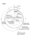
Fig. 5 is a view showing an outer shape of a rotor core of the electric motor according to the embodiment; -
Fig. 6 is a view for illustrating a developing process for an expression capable of making magnetic flux density distribution between an outer circumferential part of the rotor core of the electric motor according to the embodiment and an inner circumferential part of a stator core a sinusoidal waveform; -
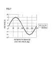
Fig. 7 is a graph showing a waveform of inductive voltage of the electric motor according to the embodiment; -
Fig. 8 is a plan view showing a rotor according to a first modified embodiment of the embodiment; -
Fig. 9 is a view showing a portion ranging from a center part to one end of a part of a stator and the rotor according to the first modified embodiment of the embodiment, the part corresponding to one magnetic pole of the permanent magnet; -
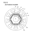
Fig. 10 is a plan view showing a stator and a rotor according to a second modified embodiment of the embodiment; -
Fig. 11 is a view showing a part between adjacent slots of the stator and the rotor according to the second modified embodiment of the embodiment; and -
Fig. 12 is a plan view showing a rotor according to a third modified embodiment of the embodiment. - Hereinafter, an embodiment of the present invention will be described with reference to the drawings.
- Firstly, with reference to
Fig. 1 , a configuration of anelectric motor 100 will be described. - As shown in
Fig. 1 , theelectric motor 100 is provided with astator 1, arotor 2,bearings 3,brackets 4, and aframe 5. - The
stator 1 and therotor 2 are arranged inside theframe 5. Thestator 1 and therotor 2 are arranged so as to face each other in the radial direction of therotor 2. Thebrackets 4 are respectively attached to both ends of theframe 5. Thebearings 3 formed by ball bearings or the like are respectively attached to thebrackets 4. It should be noted that ashaft 22 described later is provided in therotor 2 so as to pass through therotor 2. Thisshaft 22 is rotatably supported on a pair ofshaft holes 4a provided in thebrackets 4 respectively through thebearings 3. - As shown in
Fig. 2 , thestator 1 is formed by astator core 11 in which nineslots 12 are formed, andwirings 13. These nineslots 12 are formed inside thestator core 11. Theslots 12 are arranged at equal intervals along the rotation direction of arotor core 21. Thestator core 11 is provided so as to have a predetermined space (gap) to face therotor core 21 of therotor 2 described later in the radial direction. Thestator core 11 is formed by laminating magnetic steel sheets for example. Thewirings 13 are wound between theslots 12 by concentrated winding or distributed winding. It should be noted that a part of thestator core 11 between the twoadjacent slots 12 forms atooth portion 14. An outer circumferential part of thestator core 11 forms ayoke portion 15. - As shown in
Figs. 2 and3 , therotor 2 is formed by therotor core 21, theshaft 22, and sixpermanent magnets 23. Therotor core 21 is formed by laminating magnetic steel sheets for example. Theshaft 22 is provided so as to pass through a center of therotor core 21. The sixpermanent magnets 23 are buried in the vicinity of an outer circumferential part of therotor core 21. Specifically, the sixpermanent magnets 23 are respectively buried (fitted) in sixhole portions 24 formed in the vicinity of the outer circumferential part of therotor core 21. It should be noted that these sixpermanent magnets 23 are arranged in such a manner that magnetic poles on the outer circumferential side (N pole, S pole) are alternately opposite one by one along the rotation direction. Thepermanent magnets 23 are arranged at equal intervals along the rotation direction of therotor core 21. Magnetic flux generated from thepermanent magnets 23 flow in the substantially radial direction in the space (gap) between thestator core 11 and therotor core 21.Clearances 25 are provided in both ends of thepermanent magnets 23 fitted in thehole portions 24 along the rotation direction of therotor core 21. - In the present embodiment, as shown in
Figs. 3 to 5 , the outer circumferential part of therotor core 21 is formed in such a manner that a radial gap length between the outer circumferential part of therotor core 21 and an inner circumferential part of thestator core 11 for one magnetic pole of the permanent magnet 23 (length of the space (gap) between therotor core 21 and the stator core 11) becomes a gap length along agap length 1 regulated by the following expression (2) capable of making magnetic flux density distribution between the outer circumferential part of therotor core 21 and the inner circumferential part of thestator core 11 a sinusoidal waveform. It should be noted that a shape shown by an alternate long and short dash line inFigs. 3 and4 indicates a shape of the outer circumferential part of therotor core 21 in a case where the outer circumferential part of therotor core 21 is formed in such a manner that the gap length between therotor core 21 and thestator core 11 substantially matches with thegap length 1 regulated by the following expression (2) over the entire one magnetic pole of the permanent magnet 23 (theoretical shape) . -

- It should be noted that in the above expression (2), the reference sign x denotes a distance of a part of a circumference of a circle C1 (see
Figs. 3 and4 ) around a center of therotor core 21 passing between the outer circumferential part of therotor core 21 and the inner circumferential part of thestator core 11, the distance being measured from a center of the part corresponding to one magnetic pole of thepermanent magnet 23 along the circumference of the circle C1 (distance measured from a point O1 along an X1 axis inFigs. 3 and4 ). Thereference sign 1max denotes a maximum value of the gap length 1 (seeFig. 4 ), and thereference sign 1min denotes a minimum value of the gap length 1 (seeFig. 4 ). The reference sign τ1 denotes a length of the part of the circumference of the circle C1 corresponding to one magnetic pole of the permanent magnet 23 (seeFig. 3 ). A developing process for the above expression (2) will be described later. - In the present embodiment, as shown in
Fig. 4 , a portion ranging from a center part to one end of a part of the outer circumferential part of therotor core 21, the part corresponding to one magnetic pole of thepermanent magnet 23 is formed by twoarc portions 26 and 27 (a first arc portion and a second arc portion (seeFig. 5 )) continuing to each other in such a manner that the gap length between therotor core 21 and thestator core 11 becomes the gap length along thegap length 1 regulated by the above expression (2). It should be noted that in the present embodiment, the inner circumferential part of thestator core 11 is formed into a substantially perfect circle around the center 0 of the rotor core 21 (seeFig. 2 ). - As shown in
Fig. 4 , thearc portion 26 has a part (point P1) at which the gap length between therotor core 21 and thestator core 11 is minimum, and is formed in such a manner that the gap length becomes a gap length substantially matching with thegap length 1 regulated by the above expression (2). Thearc portion 27 has a part (point P2) at which the gap length between therotor core 21 and thestator core 11 is maximum, and is formed in such a manner that the gap length becomes the gap length substantially matching with thegap length 1 regulated by the above expression (2). - It should be noted that in the present embodiment, a center of the
arc portion 26 and a center of thearc portion 27 are respectively set at positions displaced from the center O of therotor core 21. Specifically, as shown inFig. 5 , a central coordinate (x1, y1) of thearc portion 26 in an XY orthogonal coordinate system taking the center O of therotor core 21 as an origin is set within a range regulated by -0.1 R0 ≤ x1 ≤ 0.1 R0 and 0 ≤ y1 ≤ 0.7 R0. A central coordinate (x2, y2) of thearc portion 27 is set within a range regulated by -0.6 R0 ≤ x2 ≤ 0 and -0.6 R0 ≤ y2 ≤ 0.5 R0. Thereby, the gap length between therotor core 21 and thestator core 11 can be made the gap length along thegap length 1 regulated by the above expression (2) with using thearc portion 26 and thearc portion 27. It should be noted that the reference sign R0 denotes a radius of a circle C2 around the center of therotor core 21 circumscribed about therotor core 21. A radius R1 of thearc portion 26 is set to be smaller than the radius R0 of the circle C2. - In the present embodiment, in the XY orthogonal coordinate system taking the center 0 of the
rotor core 21 as the origin (seeFig. 5 ) , an angle θ made by a Y axis and a straight line connecting the origin O and a point Q where thearc portion 26 and thearc portion 27 are connected is set within a range regulated by 0.45 θp ≤ θ ≤ 0.55 θp. It should be noted that the reference sign θp denotes a center angle (60 degrees) of a part of the above circle C2 corresponding to one magnetic pole of thepermanent magnet 23. - Next, with reference to
Fig. 6 , the developing process for the above expression (2) regulating thegap length 1 capable of making the magnetic flux density distribution between the outer circumferential part of therotor core 21 and the inner circumferential part of thestator core 11 a sinusoidal waveform will be described. -
Fig. 6 is an imagery view in which astator core 11a and arotor core 21a having the same configurations as thestator core 11 and therotor core 21 according to the present embodiment are developed in a straight line. An X1 axis shown inFig. 6 corresponds to the X1 axis shown inFigs. 3 and4 . InFig. 6 , slots provided in thestator core 11a, hole portions in whichpermanent magnets 23a of therotor core 21a are fitted, and the like are omitted. - Firstly, in
Fig. 6 , magnetic flux φ generated from thepermanent magnets 23a, the flux flowing through a predetermined position (position x) of a space (gap) between therotor core 21a and thestator core 11a is indicated as a function φ(x) of the position x. Similarly, magnetic resistance R and thegap length 1 at the predetermined position (position x) of the space (gap) between therotor core 21a and thestator core 11a are respectively indicated as functions R(x) and 1(x) of the position x. - Next, a
magnetic circuit 50 to cope with the magnetic flux φ(x) generated from an N pole to an S pole between the two adjacentpermanent magnets 23a will be supposed. A center in the X1 axis direction of one of the two adjacentpermanent magnets 23a is an origin O1 of the X1 axis, and a center in the X1 axis direction of the other is x = τ1. In this case, themagnetic circuit 50 is line symmetrical with respect to a straight line L extending in the direction orthogonal to the X1 axis at a position of x = τ1 / 2 in a plan view. - The magnetic flux φ(x) passing inside the
magnetic circuit 50 supposed as above, and the magnetic resistance R(x) of themagnetic circuit 50 are respectively expressed by the following expressions (3) and (4). Magnetic resistance in a part other than the gap will be ignored. -


- It should be noted that in the above expressions, the reference sign F denotes magnetomotive force of the
permanent magnets 23a, the reference sign ρ denotes a magnetic resistance rate of the space (gap) between therotor core 21a and thestator core 11a, and the reference sign ΔS denotes a cross sectional area of themagnetic circuit 50. - Thereby, magnetic flux density B (= φ / ΔS) at the predetermined position (position x) of the space (gap) between the
rotor core 21a and thestator core 11a is expressed by the following expression (5) based on the above expressions (3) and (4) . -

- In order to make distribution of the magnetic flux density B(x) at the predetermined position (position x) of the space (gap) between the
rotor core 21a and thestator core 11a a sinusoidal waveform, there is a need for establishing the following expression (6). -

- It should be noted that in the above expression (6), the reference signs A and B denote predetermined constants.
- The predetermined constants A and B are determined based on a condition that "1 = 1min (minimum value of the gap length 1)" with "x = 0", and on a condition that "1 = lmax (maximum value of the gap length 1)" with "x = τ1 /2". When the above expression (6) is rewritten based on the constants A and B determined in such a way, the above expression (2) is obtained.
- In such a way, the above expression (2) regulating the
gap length 1 in a case where the magnetic flux density distribution between the outer circumferential part of therotor core 21 and the inner circumferential part of thestator core 11 becomes a sinusoidal waveform is developed. - Next, with reference to
Fig. 7 , a waveform of the inductive voltage of theelectric motor 100 according to the present embodiment will be described. - A graph with a dotted line in
Fig. 7 is a graph showing a result of manufacturing an electric motor corresponding to the present embodiment (electric motor in which an outer circumferential part of a rotor core is formed by two arc portions, and an inner circumferential part of a stator core is formed into a substantially perfect circle, so that a gap length between the rotor core and the stator core is the gap length along the gap length l regulated by the above expression (2)), rotating the rotor at predetermined rotation speed, and actually measuring to determine a change in the inductive voltage relative to a rotation angle thereof (electric angle = actual rotation angle / number of magnetic pole). - Meanwhile, a graph with a solid line in
Fig. 7 is a graph showing a result of supposing that theelectric motor 100 according to the present embodiment is rotated at predetermined rotation speed, and simulating (analyzing) to determine a change in the inductive voltage relative to a rotation angle thereof (electric angle). - As shown in
Fig. 7 , the graph of the solid line and the graph of the dotted line are substantially overlapped with each other. It is found that both the graph of the solid line and the graph of the dotted line have a sinusoidal waveform. Thereby, it is confirmed by both the experiment and the simulation that the waveform of the inductive voltage of the electric motor in which the outer circumferential part of the rotor core is formed by the two arc portions, and the inner circumferential part of the stator core is formed into a substantially perfect circle, so that the gap length between the rotor core and the stator core is the gap length along the gap length l regulated by the above expression (2) becomes a sinusoidal waveform. - In the present embodiment, as described above, the outer circumferential part of the
rotor core 21 is formed in such a manner that the radial gap length between the outer circumferential part of therotor core 21 and the inner circumferential part of thestator core 11 for one magnetic pole of thepermanent magnet 23 becomes the gap length along thegap length 1 regulated by the above expression (2) capable of making the magnetic flux density distribution between the outer circumferential part of therotor core 21 and the inner circumferential part of thestator core 11 a sinusoidal waveform. Thereby, the magnetic flux density distribution between the outer circumferential part of therotor core 21 and the inner circumferential part of thestator core 11 can be brought closer to a sinusoidal waveform based on the above expression (2) capable of making the magnetic flux density distribution between the outer circumferential part of therotor core 21 and the inner circumferential part of thestator core 11 a sinusoidal waveform. As a result, the waveform of the inductive voltage can be brought closer to a sinusoidal waveform, and cogging torque and pulsation of torque can be more reduced, so that a servo performance of theelectric motor 100 can be more improved. - In the present embodiment, as described above, the portion ranging from the center part to one end of the part of the outer circumferential part of the
rotor core 21 corresponding to one magnetic pole of thepermanent magnet 23 is formed by the two arc portions (thearc portion 26 and the arc portion 27) continuing to each other, and the inner circumferential part of thestator core 11 is formed into a substantially perfect circle around the center 0 of therotor core 21 in such a manner that the radial gap length between the outer circumferential part of therotor core 21 and the inner circumferential part of thestator core 11 becomes the gap length along thegap length 1 regulated by the above expression (2) . Thereby, by the two arc portions (thearc portion 26 and the arc portion 27) continuing to each other and the inner peripheral part of thestator core 11 formed into a substantially perfect circle, the radial gap length between the outer circumferential part of therotor core 21 and the inner circumferential part of thestator core 11 can be easily made the gap length along thegap length 1 regulated by the above expression (2). - 1 In the present embodiment, as described above, the
arc portion 26 has the part (point P1) at which the radial gap length between the outer circumferential part of therotor core 21 and the inner circumferential part of thestator core 11 is minimum, and is formed in such a manner that the radial gap length between thearc portion 26 and the inner circumferential part of thestator core 11 becomes the gap length substantially matching with thegap length 1 regulated by the above expression (2). Thearc portion 27 has the part (point P2) at which the radial gap length between the outer circumferential part of therotor core 21 and the inner circumferential part of thestator core 11 is maximum, and is formed in such a manner that the radial gap length between thearc portion 27 and the inner circumferential part of thestator core 11 becomes the gap length substantially matching with thegap length 1 regulated by the above expression (2) . The magnetic flux flowing in the space (gap) between therotor core 21 and thestator core 11 does not easily flow in the radial direction as the gap length thereof is increased. Thus, the magnetic flux density in a part with the large gap length between therotor core 21 and thestator core 11 is smaller than the magnetic flux in the center part of the part of the outer circumferential part of therotor core 21 corresponding to one magnetic pole of thepermanent magnet 23. Therefore, an influence of a shape of therotor core 21 in the part with the large gap length between therotor core 21 and thestator core 11 on a performance of theelectric motor 100 such as the cogging torque and the pulsation of the torque is smaller than an influence of a shape of therotor core 21 in the center part of the part of the outer circumferential part of therotor core 21 corresponding to one magnetic pole of thepermanent magnet 23 and a part in the vicinity of the part on the performance of theelectric motor 100. Thus, as in the present embodiment, by forming the outer circumferential part of therotor core 21 by thearc portion 26 and thearc portion 27, so that the gap length other than the vicinity of the part in which the gap length between therotor core 21 and thestator core 11 is maximum is made the gap length along the gap length l regulated by the above expression (2), the magnetic flux density distribution between the outer circumferential part of therotor core 21 and the inner circumferential part of thestator core 11 can be brought close to a sinusoidal waveform. - 1 In the present embodiment, as described above, the center of the
arc portion 26 and the center of thearc portion 27 are respectively set at the positions displaced from the center 0 of therotor core 21. Thereby, by thearc portion 26 and thearc portion 27, the radial gap length between the outer circumferential part of therotor core 21 and the inner circumferential part of thestator core 11 can be easily made the gap length along thegap length 1 regulated by the above expression (2). - In the present embodiment, as described above, the radius R1 of the
arc portion 26 is set to be smaller than the radius R0 of the circle C2 circumscribed about therotor core 21. Preferably, a radius R2 of thearc portion 27 is set to be larger than the radius R0 of the circle C2 circumscribed about therotor core 21. Thereby, by thearc portion 26 and thearc portion 27 having different radiuses, the radial gap length between the outer circumferential part of therotor core 21 and the inner circumferential part of thestator core 11 can be easily made the gap length along thegap length 1 regulated by the above expression (2). - In the present embodiment, as described above, the central coordinate (x1, y1) of the arc portion 26 (first arc portion) in the XY orthogonal coordinate system taking the center 0 of the
rotor core 21 as the origin is set within the range regulated by -0.1 R0 ≤ x1 ≤ 0.1 R0 and 0 ≤ y1 ≤ 0.7 R0. The central coordinate (x2, y2) of the arc portion 27 (second arc portion) is set within the range regulated by -0.6 R0 ≤ x2 ≤ 0 and -0.6 R0 ≤ y2 ≤ 0.5 R0. In the XY orthogonal coordinate system taking the center 0 of therotor core 21 as the origin, the angle θ made by the Y axis and the straight line connecting the origin O and the point where thearc portion 26 and thearc portion 27 are connected is set within the range regulated by 0.45 θp ≤ θ ≤ 0.55 θp. Thereby, the radial gap length between the outer circumferential part of therotor core 21 and the inner circumferential part of thestator core 11 can be made the gap length along thegap length 1 regulated by the above expression (2) . - It should be noted that the embodiment disclosed herein is considered to be not limitation but an example in all respects. The scope of the present invention is indicated not by the above description of the embodiment but by the claims, and includes all modifications with equal meanings to the claims within a range of the claims.
- For example, although the above embodiment shows the example that by forming the part of the outer circumferential part of the rotor core corresponding to one magnetic pole of the permanent magnet by the two arc portions continuing to each other, the gap length between the rotor core and the stator core is made the gap length along the
gap length 1 regulated by the above expression (2), the present invention is not limited to this. As long as the gap length between the rotor core and the stator core becomes the gap length along thegap length 1 regulated by the above expression (2), the part of the outer circumferential part of the rotor core corresponding to one magnetic pole of the permanent magnet may be formed by three or more arc portions or may be formed by curved portions or straight line portions having other shapes than an arc shape. - By forming the outer circumferential part of the rotor core into a theoretical shape as shown by the dashed and dotted line in
Figs. 3 and4 , the gap length between the rotor core and the stator core may be made the gap length substantially matching with thegap length 1 regulated by the above expression (2) over the entire one magnetic pole of the permanent magnet. In such a way, the magnetic flux density distribution between the outer circumferential part of the rotor core and the inner circumferential part of the stator core can be brought further close to a sinusoidal waveform. - As in a first modified embodiment shown in
Figs. 8 and9 , a part of an outer circumferential part of arotor core 21b corresponding to one magnetic pole of thepermanent magnet 23 may be formed by onearc portion 28 and onestraight line portion 29 continuing to each other. In this first modified embodiment, thearc portion 28 has a part (point P3) at which a radial gap length between the outer circumferential part of therotor core 21b and the inner circumferential part of thestator core 11 is minimum, and is formed in such a manner that the gap length becomes the gap length substantially matching with thegap length 1 regulated by the above expression (2). Thestraight line portion 29 has a part (point P4) at which the radial gap length between the outer circumferential part of therotor core 21b and the inner circumferential part of thestator core 11 is maximum, and is formed in such a manner that the gap length becomes the gap length substantially matching with thegap length 1 regulated by the above expression (2). - As in a second modified embodiment shown in
Figs. 10 and11 , by forming a portion ranging from a center part to one end of a part of an inner circumferential part of astator core 11b, the part being positioned between theadjacent slots 12 by twoarc portions 16 and 17 (first and second arc portions) continuing to each other, a gap length between arotor core 21c and thestator core 11b may be made the gap length along thegap length 1 regulated by the following expression (7). It should be noted that in this second modified embodiment, an outer circumferential part of therotor core 21c is formed into a substantially perfect circle. -

- In the expression (7), the reference sign x denotes a distance of a part of a circumference of a circle C3 around a center O of the
rotor core 21c passing between the outer circumferential part of therotor core 21c and the inner circumferential part of thestator core 11b, the distance being measured from a center of the part corresponding to thetooth portion 14 along the circumference of the circle C3 (distance measured from apoint 02 along an X2 axis inFig. 11 ). Thereference sign 1max denotes a maximum value of the gap length 1 (seeFig. 11 ), and thereference sign 1min denotes a minimum value of the gap length 1 (seeFig. 11 ). The reference sign τ2 denotes a distance in the direction along the circle C3 between the adjacent slots 12 (slot pitch (seeFig. 11 )). A developing process for the above expression (7) is the same as the developing process for the above expression (2). - As shown in
Fig. 11 , thearc portion 16 has a part (point P5) at which the gap length between therotor core 21c and thestator core 11b is minimum, and is formed in such a manner that the gap length becomes the gap length substantially matching with thegap length 1 regulated by the expression (7) . Thearc portion 17 has a part (point P6) at which the gap length between therotor core 21c and thestator core 11b is maximum, and is formed in such a manner that the gap length becomes the gap length substantially matching with thegap length 1 regulated by the expression (7). - Although the above embodiment shows the example that the six
permanent magnets 23 are buried in the vicinity of the outer circumferential part of therotor core 21, and the sixpermanent magnets 23 are arranged in such a manner that the magnetic poles on the outer circumferential side (N pole, S pole) are alternately opposite one by one along the rotation direction, the present invention is not limited to this. As in a third modified embodiment shown inFig. 12 , twelvepermanent magnets 23b may be buried in the vicinity of an outer circumferential part of arotor core 21d, and the twelvepermanent magnets 23b may be arranged in such a manner that magnetic poles on the outer circumferential side (N pole, S pole) are alternately opposite two by two along the rotation direction. In this third modified embodiment, the two adjacentpermanent magnets 23b having the same magnetic pole on the outer circumferential side are arranged in a V shape. Specifically, the two adjacentpermanent magnets 23b having the same magnetic pole on the outer circumferential side are arranged in such a manner that adjacent parts of thepermanent magnets 23b are inclined to go toward a center 0 of therotor core 21d. The twelvepermanent magnets 23b are respectively buried (fitted) in twelvehole portions 24a formed in the vicinity of the outer circumferential part of therotor core 21d. It should be noted thatclearances 25a are provided in both ends of thepermanent magnets 23b fitted in thehole portions 24a. In such a way, magnetic flux generated from the vicinity of the adjacent parts of the two adjacentpermanent magnets 23b (one magnetic pole) having the same magnetic pole on the outer circumferential side toward the outer circumferential part of therotor core 21d can be increased.
Claims (11)
- An electric motor, comprising:a rotor core;a stator core provided so as to face the rotor core in the radial direction; anda permanent magnet buried in the vicinity of an outer circumferential part of the rotor core, whereinthe outer circumferential part of the rotor core and an inner circumferential part of the stator core are formed in such a manner that a radial gap length between the outer circumferential part of the rotor core and the inner circumferential part of the stator core for one magnetic pole of the permanent magnet becomes a gap length along a gap length l regulated by the following expression (1) capable of making magnetic flux density distribution between the outer circumferential part of the rotor core and the inner circumferential part of the stator core a sinusoidal waveform:[Expression 1]wherein in the expression (1), the reference sign x denotes a distance of a part of a circumference of a circle around a center of the rotor core passing between the outer circumferential part of the rotor core and the inner circumferential part of the stator core, the distance being measured from a center of the part corresponding to one magnetic pole of the permanent magnet along the circumference of the circle, the reference sign lmax denotes a maximum value of the gap length 1, the reference sign 1min denotes a minimum value of the gap length 1, and the reference sign τ denotes a length of the part of the circumference of the circle around the center of the rotor core passing between the outer circumferential part of the rotor core and the inner circumferential part of the stator core, the part corresponding to one magnetic pole of the permanent magnet.

- The electric motor according to claim 1, wherein
a portion ranging from a center part to one end of a part of at least one of the outer circumferential part of the rotor core and the inner circumferential part of the stator core, the part corresponding to one magnetic pole of the permanent magnet is formed by a plurality of arc portions continuing to each other in such a manner that the radial gap length between the outer circumferential part of the rotor core and the inner circumferential part of the stator core becomes the gap length along the gap length 1 regulated by the expression (1). - The electric motor according to claim 2, wherein
the portion ranging from the center part to one end of the part of at least one of the outer circumferential part of the rotor core and the inner circumferential part of the stator core, the part corresponding to one magnetic pole of the permanent magnet is formed by a first arc portion and a second arc portion continuing to each other in such a manner that the radial gap length between the outer circumferential part of the rotor core and the inner circumferential part of the stator core becomes the gap length along the gap length l regulated by the expression (1). - The electric motor according to claim 3, wherein
the portion ranging from the center part to one end of the part of the outer circumferential part of the rotor core, the part corresponding to one magnet pole of the permanent magnet is formed by the first arc portion and the second arc portion continuing to each other, and the inner circumferential part of the stator core is formed into a substantially perfect circle around the center of the rotor core in such a manner that the radial gap length between the outer circumferential part of the rotor core and the inner circumferential part of the stator core becomes the gap length along the gap length 1 regulated by the expression (1). - The electric motor according to claim 4, wherein
the first arc portion has a part at which the radial gap length between the outer circumferential part of the rotor core and the inner circumferential part of the stator core is minimum, and is formed in such a manner that a radial gap length between the first arc portion and the inner circumferential part of the stator core becomes a gap length substantially matching with the gap length l regulated by the expression (1), and
the second arc portion has a part at which the radial gap length between the outer circumferential part of the rotor core and the inner circumferential part of the stator core is maximum, and is formed in such a manner that a radial gap length between a part of the second arc portion other than the vicinity of the part at which the gap length is maximum and the inner circumferential part of the stator core becomes the gap length substantially matching with the gap length 1 regulated by the expression (1). - The electric motor according to claim 5, wherein
a center of the first arc portion and a center of the second arc portion are respectively set at positions displaced from the center of the rotor core. - The electric motor according to claim 6, wherein
a radius of the first arc portion is set to be smaller than a radius of a circle circumscribed about the rotor core. - The electric motor according to any one of claims 4 to 7, wherein
in a case where a radius of a circle around the center of the rotor core circumscribed about the rotor core is R0, and a center angle of a part of the circle around the center of the rotor core circumscribed about the rotor core, the part corresponding to one magnetic pole of the permanent magnet is θp,
a central coordinate (x1, y1) of the first arc portion in a XY orthogonal coordinate system taking the center of the rotor core as an origin is set within a range regulated by - 0.1 R0 ≤ x1 ≤ 0.1 R0 and 0 ≤ y1 ≤ 0.7 R0,
a central coordinate (x2, y2) of the second arc portion in the XY orthogonal coordinate system is set within a range regulated by -0.6 R0 ≤ x2 ≤ 0 and -0.6 R0 ≤ y2 ≤ 0.5 R0, and
in the XY orthogonal coordinate system, an angle θ made by a Y axis and a straight line connecting the origin and a point where the first arc portion and the second arc portion are connected is set within a range regulated by 0.45 θp ≤ θ ≤ 0.55 θp. - The electric motor according to claim 1, wherein
the outer circumferential part of the rotor core and the inner circumferential part of the stator core are formed in such a manner that the radial gap length between the outer circumferential part of the rotor core and the inner circumferential part of the stator core substantially matches with the gap length l regulated by the expression (1) over the entire one magnetic pole of the permanent magnet. - The electric motor according to claim 1, wherein
a portion ranging from a center part to one end of a part of the outer circumferential part of the rotor core, the part corresponding to one magnet pole of the permanent magnet is formed by one arc portion and one straight line portion continuing to each other, and the inner circumferential part of the stator core is formed into a substantially perfect circle around the center of the rotor core in such a manner that the radial gap length between the outer circumferential part of the rotor core and the inner circumferential part of the stator core becomes the gap length along the gap length 1 regulated by the expression (1). - The electric motor according to claim 10, wherein
the one arc portion has a part at which the radial gap length between the outer circumferential part of the rotor core and the inner circumferential part of the stator core is minimum, and is formed in such a manner that a radial gap length between the one arc portion and the inner circumferential part of the stator core becomes a gap length substantially matching with the gap length l regulated by the expression (1), and
the one straight line portion has a part at which the radial gap length between the outer circumferential part of the rotor core and the inner circumferential part of the stator core is maximum, and is formed in such a manner that a radial gap length between a part of the one straight line portion other than the vicinity of the part at which the gap length is maximum and the inner circumferential part of the stator core becomes the gap length substantially matching with the gap length 1 regulated by the expression (1).
Applications Claiming Priority (1)
| Application Number | Priority Date | Filing Date | Title |
|---|---|---|---|
| JP2010272536A JP5413358B2 (en) | 2010-12-07 | 2010-12-07 | Electric motor |
Publications (1)
| Publication Number | Publication Date |
|---|---|
| EP2463988A2 true EP2463988A2 (en) | 2012-06-13 |
Family
ID=45440083
Family Applications (1)
| Application Number | Title | Priority Date | Filing Date |
|---|---|---|---|
| EP11189243A Withdrawn EP2463988A2 (en) | 2010-12-07 | 2011-11-15 | Electric motor |
Country Status (5)
| Country | Link |
|---|---|
| US (1) | US20120139386A1 (en) |
| EP (1) | EP2463988A2 (en) |
| JP (1) | JP5413358B2 (en) |
| KR (1) | KR20120063452A (en) |
| CN (1) | CN102570636A (en) |
Cited By (11)
| Publication number | Priority date | Publication date | Assignee | Title |
|---|---|---|---|---|
| WO2014003730A1 (en) * | 2012-06-26 | 2014-01-03 | Nissan Motor Co., Ltd. | Variable magnetic flux-type rotary electric machine |
| EP2712062A3 (en) * | 2012-09-21 | 2015-11-04 | Sanyo Denki Co., Ltd. | Permanent magnet-embedded rotor and motor thereof |
| EP3154176A1 (en) * | 2015-10-08 | 2017-04-12 | BSH Hausgeräte GmbH | Electrical drive motor |
| EP2958228A4 (en) * | 2013-02-12 | 2017-08-02 | Mitsubishi Electric Corporation | Motor drive device |
| EP3457546A4 (en) * | 2016-05-10 | 2019-05-22 | Mitsubishi Electric Corporation | PERMANENT MAGNET MOTOR |
| EP3457547A4 (en) * | 2016-05-10 | 2019-05-22 | Mitsubishi Electric Corporation | PERMANENT MAGNET MOTOR |
| FR3104848A1 (en) * | 2019-12-17 | 2021-06-18 | IFP Energies Nouvelles | Synchro-reluctant machine with variable air gap |
| WO2021140171A1 (en) * | 2020-01-10 | 2021-07-15 | Metabowerke Gmbh | Arrangement comprising a stator laminate and a rotor laminate |
| CN115552768A (en) * | 2020-05-15 | 2022-12-30 | 松下知识产权经营株式会社 | Rotor and motor |
| IT202300017895A1 (en) * | 2023-08-30 | 2025-03-02 | C F R Soc A Responsabilita Limitata | ELECTRIC MOTOR |
| WO2025176267A1 (en) * | 2024-02-23 | 2025-08-28 | Schaeffler Technologies AG & Co. KG | Sinusoidal surface of the rotor and stator |
Families Citing this family (17)
| Publication number | Priority date | Publication date | Assignee | Title |
|---|---|---|---|---|
| KR101307047B1 (en) * | 2012-03-06 | 2013-09-11 | 한양대학교 에리카산학협력단 | Permanent magnet motor |
| JP6033424B2 (en) * | 2012-06-26 | 2016-11-30 | 日産自動車株式会社 | Variable magnetomotive force type rotating electrical machine and control device for variable magnetomotive force type rotating electrical machine |
| JP2014054153A (en) * | 2012-09-10 | 2014-03-20 | Nsk Ltd | Electric motor and electric power steering device |
| JP2014054154A (en) * | 2012-09-10 | 2014-03-20 | Nsk Ltd | Electric motor and electric power steering device |
| JP6379462B2 (en) * | 2013-09-03 | 2018-08-29 | 富士電機株式会社 | Permanent magnet embedded rotary electric machine |
| TWI508414B (en) * | 2013-11-12 | 2015-11-11 | Hon Hai Prec Ind Co Ltd | Rotor and motor using the same |
| CN104638786A (en) * | 2013-11-13 | 2015-05-20 | 鸿富锦精密工业(深圳)有限公司 | Rotor and motor adopting same |
| EP3567704B1 (en) * | 2017-01-04 | 2022-05-18 | LG Innotek Co., Ltd. | Motor and transmission |
| KR102030660B1 (en) * | 2018-04-27 | 2019-10-10 | 한양대학교 산학협력단 | Method for designing rotor of synchronous motor and the rotor designed by the method |
| CN112152348B (en) * | 2019-06-27 | 2022-01-04 | 台达电子工业股份有限公司 | Rotor lamination and rotor assembly suitable for same |
| JPWO2022019074A1 (en) * | 2020-07-22 | 2022-01-27 | ||
| US11575285B2 (en) * | 2020-12-09 | 2023-02-07 | Ford Global Technologies, Llc | Electric machine |
| EP4297243A4 (en) * | 2021-02-16 | 2024-10-02 | Toyota Jidosha Kabushiki Kaisha | Rotor |
| JP7615847B2 (en) * | 2021-04-05 | 2025-01-17 | 株式会社デンソー | Rotor and rotating electric machine |
| TWI801840B (en) * | 2021-04-14 | 2023-05-11 | 東元電機股份有限公司 | Rotor structure with edge notches |
| KR102823396B1 (en) * | 2021-04-27 | 2025-06-20 | 한온시스템 주식회사 | Brushless Motor |
| US11646617B2 (en) * | 2021-08-30 | 2023-05-09 | Hiwin Mikrosystem Corp. | High-frequency rotating structure with permanent magnet rotor having grooves and magnetic barrier spaces |
Citations (1)
| Publication number | Priority date | Publication date | Assignee | Title |
|---|---|---|---|---|
| JP2000197292A (en) | 1998-10-21 | 2000-07-14 | Mitsubishi Electric Corp | Permanent magnet type rotor of permanent magnet type electric motor |
Family Cites Families (4)
| Publication number | Priority date | Publication date | Assignee | Title |
|---|---|---|---|---|
| JP2001069701A (en) * | 1999-08-30 | 2001-03-16 | Mitsubishi Heavy Ind Ltd | Magnet motor |
| JP2003037955A (en) * | 2001-07-24 | 2003-02-07 | Mitsubishi Heavy Ind Ltd | Rotor for magnetic motor |
| US8405270B2 (en) * | 2007-05-07 | 2013-03-26 | Panasonic Corporation | Permanent magnet buried type electric motor |
| DE102007041099A1 (en) * | 2007-08-30 | 2009-03-05 | Robert Bosch Gmbh | Rotor arrangement for an electric machine |
-
2010
- 2010-12-07 JP JP2010272536A patent/JP5413358B2/en not_active Expired - Fee Related
-
2011
- 2011-11-04 US US13/289,027 patent/US20120139386A1/en not_active Abandoned
- 2011-11-15 EP EP11189243A patent/EP2463988A2/en not_active Withdrawn
- 2011-11-30 CN CN2011103911436A patent/CN102570636A/en active Pending
- 2011-12-07 KR KR1020110130506A patent/KR20120063452A/en not_active Ceased
Patent Citations (1)
| Publication number | Priority date | Publication date | Assignee | Title |
|---|---|---|---|---|
| JP2000197292A (en) | 1998-10-21 | 2000-07-14 | Mitsubishi Electric Corp | Permanent magnet type rotor of permanent magnet type electric motor |
Cited By (19)
| Publication number | Priority date | Publication date | Assignee | Title |
|---|---|---|---|---|
| WO2014003730A1 (en) * | 2012-06-26 | 2014-01-03 | Nissan Motor Co., Ltd. | Variable magnetic flux-type rotary electric machine |
| CN104412493A (en) * | 2012-06-26 | 2015-03-11 | 日产自动车株式会社 | Variable magnetic flux-type rotary electric machine |
| US9692265B2 (en) | 2012-06-26 | 2017-06-27 | Nissan Motor Co., Ltd. | Variable magnetic flux-type rotary electric machine |
| EP2712062A3 (en) * | 2012-09-21 | 2015-11-04 | Sanyo Denki Co., Ltd. | Permanent magnet-embedded rotor and motor thereof |
| US10014736B2 (en) | 2012-09-21 | 2018-07-03 | Sanyo Denki Co., Ltd. | Permanent magnet-embedded motor and rotor thereof |
| EP2958228A4 (en) * | 2013-02-12 | 2017-08-02 | Mitsubishi Electric Corporation | Motor drive device |
| EP3337028A1 (en) * | 2013-02-12 | 2018-06-20 | Mitsubishi Electric Corporation | Motor drive device |
| EP3154176A1 (en) * | 2015-10-08 | 2017-04-12 | BSH Hausgeräte GmbH | Electrical drive motor |
| EP3457546A4 (en) * | 2016-05-10 | 2019-05-22 | Mitsubishi Electric Corporation | PERMANENT MAGNET MOTOR |
| EP3457547A4 (en) * | 2016-05-10 | 2019-05-22 | Mitsubishi Electric Corporation | PERMANENT MAGNET MOTOR |
| US10916983B2 (en) | 2016-05-10 | 2021-02-09 | Mitsubishi Electric Corporation | Permanent-magnet motor |
| US11108312B2 (en) | 2016-05-10 | 2021-08-31 | Mitsubishi Electric Corporation | Permanent-magnet motor including v-shaped permanent-magnet pairs |
| FR3104848A1 (en) * | 2019-12-17 | 2021-06-18 | IFP Energies Nouvelles | Synchro-reluctant machine with variable air gap |
| WO2021122044A1 (en) * | 2019-12-17 | 2021-06-24 | IFP Energies Nouvelles | Synchronous reluctance machine having a variable air gap |
| WO2021140171A1 (en) * | 2020-01-10 | 2021-07-15 | Metabowerke Gmbh | Arrangement comprising a stator laminate and a rotor laminate |
| CN115552768A (en) * | 2020-05-15 | 2022-12-30 | 松下知识产权经营株式会社 | Rotor and motor |
| EP4152568A4 (en) * | 2020-05-15 | 2023-11-22 | Panasonic Intellectual Property Management Co., Ltd. | Rotor and electric motor |
| IT202300017895A1 (en) * | 2023-08-30 | 2025-03-02 | C F R Soc A Responsabilita Limitata | ELECTRIC MOTOR |
| WO2025176267A1 (en) * | 2024-02-23 | 2025-08-28 | Schaeffler Technologies AG & Co. KG | Sinusoidal surface of the rotor and stator |
Also Published As
| Publication number | Publication date |
|---|---|
| JP2012125016A (en) | 2012-06-28 |
| JP5413358B2 (en) | 2014-02-12 |
| KR20120063452A (en) | 2012-06-15 |
| US20120139386A1 (en) | 2012-06-07 |
| CN102570636A (en) | 2012-07-11 |
Similar Documents
| Publication | Publication Date | Title |
|---|---|---|
| US20120139386A1 (en) | Electric motor | |
| US9595851B2 (en) | Rotary electric machine | |
| KR101076570B1 (en) | Permanent magnet buried type electric motor | |
| KR101880377B1 (en) | Interior permanent magnet rotating electric machine | |
| US11171525B2 (en) | Rotor and permanent magnet electric motor | |
| JP5936060B2 (en) | Rotating electrical machine rotor | |
| CN103518313B (en) | Permanent magnet type rotating electrical machine | |
| EP0841738A1 (en) | Motor | |
| EP2843804A2 (en) | Permanent magnet-embedded type rotary electric machine | |
| US11190070B2 (en) | Rotor for rotating electrical machine | |
| WO2018051690A1 (en) | Rotor and reluctance motor | |
| US11264878B2 (en) | Rotor for rotary electric machine and method of manufacturing rotary electric machine | |
| JP2021016205A (en) | Synchronous reluctance motor | |
| US20240283308A1 (en) | Rotor and motor | |
| JP7101869B2 (en) | Synchronous reluctance motor | |
| JP2015233368A (en) | Permanent magnet motor | |
| CN116472658B (en) | Rotating motor and electric power steering device | |
| JP4396142B2 (en) | Permanent magnet rotating electric machine | |
| JPH10304606A (en) | Permanent magnet motor | |
| JP2023005389A (en) | Rotor core and rotary electric machine | |
| WO2024224777A1 (en) | Rotor | |
| WO2024224773A1 (en) | Rotor | |
| WO2024224774A1 (en) | Rotor | |
| WO2024224776A1 (en) | Rotor | |
| WO2024224775A1 (en) | Rotor |
Legal Events
| Date | Code | Title | Description |
|---|---|---|---|
| PUAI | Public reference made under article 153(3) epc to a published international application that has entered the european phase |
Free format text: ORIGINAL CODE: 0009012 |
|
| AK | Designated contracting states |
Kind code of ref document: A2 Designated state(s): AL AT BE BG CH CY CZ DE DK EE ES FI FR GB GR HR HU IE IS IT LI LT LU LV MC MK MT NL NO PL PT RO RS SE SI SK SM TR |
|
| AX | Request for extension of the european patent |
Extension state: BA ME |
|
| STAA | Information on the status of an ep patent application or granted ep patent |
Free format text: STATUS: THE APPLICATION HAS BEEN WITHDRAWN |
|
| 18W | Application withdrawn |
Effective date: 20140320 |