EP2463594A1 - Air evacuation device, heat exchange unit and fixing tool - Google Patents
Air evacuation device, heat exchange unit and fixing tool Download PDFInfo
- Publication number
- EP2463594A1 EP2463594A1 EP10781396A EP10781396A EP2463594A1 EP 2463594 A1 EP2463594 A1 EP 2463594A1 EP 10781396 A EP10781396 A EP 10781396A EP 10781396 A EP10781396 A EP 10781396A EP 2463594 A1 EP2463594 A1 EP 2463594A1
- Authority
- EP
- European Patent Office
- Prior art keywords
- heat exchanger
- valve
- exchange unit
- heat exchange
- front surface
- Prior art date
- Legal status (The legal status is an assumption and is not a legal conclusion. Google has not performed a legal analysis and makes no representation as to the accuracy of the status listed.)
- Granted
Links
- 238000012423 maintenance Methods 0.000 claims abstract description 23
- 238000013022 venting Methods 0.000 claims description 51
- 230000001681 protective effect Effects 0.000 claims description 37
- 238000012546 transfer Methods 0.000 claims description 27
- 239000003638 chemical reducing agent Substances 0.000 claims description 7
- 230000003100 immobilizing effect Effects 0.000 claims description 2
- 230000003313 weakening effect Effects 0.000 claims description 2
- XLYOFNOQVPJJNP-UHFFFAOYSA-N water Substances O XLYOFNOQVPJJNP-UHFFFAOYSA-N 0.000 description 87
- 239000010408 film Substances 0.000 description 32
- 238000000034 method Methods 0.000 description 11
- 239000000463 material Substances 0.000 description 7
- -1 polypropylene Polymers 0.000 description 7
- 230000002411 adverse Effects 0.000 description 6
- 238000003780 insertion Methods 0.000 description 6
- 230000037431 insertion Effects 0.000 description 6
- 239000004743 Polypropylene Substances 0.000 description 5
- 230000000694 effects Effects 0.000 description 5
- 229920001155 polypropylene Polymers 0.000 description 5
- 230000005494 condensation Effects 0.000 description 4
- 238000009833 condensation Methods 0.000 description 4
- 230000007423 decrease Effects 0.000 description 4
- 238000009434 installation Methods 0.000 description 4
- 239000000853 adhesive Substances 0.000 description 3
- 230000001070 adhesive effect Effects 0.000 description 3
- 230000002829 reductive effect Effects 0.000 description 3
- 238000005452 bending Methods 0.000 description 2
- 230000001143 conditioned effect Effects 0.000 description 2
- 238000010586 diagram Methods 0.000 description 2
- 238000005304 joining Methods 0.000 description 2
- 238000000465 moulding Methods 0.000 description 2
- 238000010137 moulding (plastic) Methods 0.000 description 2
- 239000004033 plastic Substances 0.000 description 2
- 229920003023 plastic Polymers 0.000 description 2
- 229920000139 polyethylene terephthalate Polymers 0.000 description 2
- 239000005020 polyethylene terephthalate Substances 0.000 description 2
- 238000009423 ventilation Methods 0.000 description 2
- 241001417523 Plesiopidae Species 0.000 description 1
- 208000027418 Wounds and injury Diseases 0.000 description 1
- 230000002159 abnormal effect Effects 0.000 description 1
- 238000004378 air conditioning Methods 0.000 description 1
- 238000007664 blowing Methods 0.000 description 1
- 230000006378 damage Effects 0.000 description 1
- 230000003247 decreasing effect Effects 0.000 description 1
- 238000013461 design Methods 0.000 description 1
- 239000000835 fiber Substances 0.000 description 1
- 208000014674 injury Diseases 0.000 description 1
- 238000003754 machining Methods 0.000 description 1
- 238000004519 manufacturing process Methods 0.000 description 1
- 238000012986 modification Methods 0.000 description 1
- 230000004048 modification Effects 0.000 description 1
- 230000002093 peripheral effect Effects 0.000 description 1
- 238000003825 pressing Methods 0.000 description 1
- 238000012545 processing Methods 0.000 description 1
- 230000008439 repair process Effects 0.000 description 1
- 230000000630 rising effect Effects 0.000 description 1
- 239000010409 thin film Substances 0.000 description 1
- 238000011144 upstream manufacturing Methods 0.000 description 1
Images





Classifications
-
- F—MECHANICAL ENGINEERING; LIGHTING; HEATING; WEAPONS; BLASTING
- F24—HEATING; RANGES; VENTILATING
- F24D—DOMESTIC- OR SPACE-HEATING SYSTEMS, e.g. CENTRAL HEATING SYSTEMS; DOMESTIC HOT-WATER SUPPLY SYSTEMS; ELEMENTS OR COMPONENTS THEREFOR
- F24D19/00—Details
- F24D19/08—Arrangements for drainage, venting or aerating
- F24D19/082—Arrangements for drainage, venting or aerating for water heating systems
- F24D19/083—Venting arrangements
-
- F—MECHANICAL ENGINEERING; LIGHTING; HEATING; WEAPONS; BLASTING
- F24—HEATING; RANGES; VENTILATING
- F24F—AIR-CONDITIONING; AIR-HUMIDIFICATION; VENTILATION; USE OF AIR CURRENTS FOR SCREENING
- F24F1/00—Room units for air-conditioning, e.g. separate or self-contained units or units receiving primary air from a central station
- F24F1/0007—Indoor units, e.g. fan coil units
- F24F1/0059—Indoor units, e.g. fan coil units characterised by heat exchangers
-
- F—MECHANICAL ENGINEERING; LIGHTING; HEATING; WEAPONS; BLASTING
- F24—HEATING; RANGES; VENTILATING
- F24F—AIR-CONDITIONING; AIR-HUMIDIFICATION; VENTILATION; USE OF AIR CURRENTS FOR SCREENING
- F24F1/00—Room units for air-conditioning, e.g. separate or self-contained units or units receiving primary air from a central station
- F24F1/0007—Indoor units, e.g. fan coil units
- F24F1/0059—Indoor units, e.g. fan coil units characterised by heat exchangers
- F24F1/0063—Indoor units, e.g. fan coil units characterised by heat exchangers by the mounting or arrangement of the heat exchangers
-
- F—MECHANICAL ENGINEERING; LIGHTING; HEATING; WEAPONS; BLASTING
- F24—HEATING; RANGES; VENTILATING
- F24F—AIR-CONDITIONING; AIR-HUMIDIFICATION; VENTILATION; USE OF AIR CURRENTS FOR SCREENING
- F24F1/00—Room units for air-conditioning, e.g. separate or self-contained units or units receiving primary air from a central station
- F24F1/0007—Indoor units, e.g. fan coil units
- F24F1/0068—Indoor units, e.g. fan coil units characterised by the arrangement of refrigerant piping outside the heat exchanger within the unit casing
-
- F—MECHANICAL ENGINEERING; LIGHTING; HEATING; WEAPONS; BLASTING
- F28—HEAT EXCHANGE IN GENERAL
- F28F—DETAILS OF HEAT-EXCHANGE AND HEAT-TRANSFER APPARATUS, OF GENERAL APPLICATION
- F28F9/00—Casings; Header boxes; Auxiliary supports for elements; Auxiliary members within casings
- F28F9/001—Casings in the form of plate-like arrangements; Frames enclosing a heat exchange core
- F28F9/002—Casings in the form of plate-like arrangements; Frames enclosing a heat exchange core with fastening means for other structures
-
- F—MECHANICAL ENGINEERING; LIGHTING; HEATING; WEAPONS; BLASTING
- F24—HEATING; RANGES; VENTILATING
- F24D—DOMESTIC- OR SPACE-HEATING SYSTEMS, e.g. CENTRAL HEATING SYSTEMS; DOMESTIC HOT-WATER SUPPLY SYSTEMS; ELEMENTS OR COMPONENTS THEREFOR
- F24D19/00—Details
- F24D19/008—Details related to central heating radiators
- F24D19/0087—Fan arrangements for forced convection
-
- F—MECHANICAL ENGINEERING; LIGHTING; HEATING; WEAPONS; BLASTING
- F24—HEATING; RANGES; VENTILATING
- F24F—AIR-CONDITIONING; AIR-HUMIDIFICATION; VENTILATION; USE OF AIR CURRENTS FOR SCREENING
- F24F1/00—Room units for air-conditioning, e.g. separate or self-contained units or units receiving primary air from a central station
- F24F1/0007—Indoor units, e.g. fan coil units
- F24F1/0018—Indoor units, e.g. fan coil units characterised by fans
- F24F1/0022—Centrifugal or radial fans
-
- F—MECHANICAL ENGINEERING; LIGHTING; HEATING; WEAPONS; BLASTING
- F24—HEATING; RANGES; VENTILATING
- F24F—AIR-CONDITIONING; AIR-HUMIDIFICATION; VENTILATION; USE OF AIR CURRENTS FOR SCREENING
- F24F1/00—Room units for air-conditioning, e.g. separate or self-contained units or units receiving primary air from a central station
- F24F1/0007—Indoor units, e.g. fan coil units
- F24F1/0043—Indoor units, e.g. fan coil units characterised by mounting arrangements
- F24F1/0057—Indoor units, e.g. fan coil units characterised by mounting arrangements mounted in or on a wall
-
- F—MECHANICAL ENGINEERING; LIGHTING; HEATING; WEAPONS; BLASTING
- F28—HEAT EXCHANGE IN GENERAL
- F28D—HEAT-EXCHANGE APPARATUS, NOT PROVIDED FOR IN ANOTHER SUBCLASS, IN WHICH THE HEAT-EXCHANGE MEDIA DO NOT COME INTO DIRECT CONTACT
- F28D1/00—Heat-exchange apparatus having stationary conduit assemblies for one heat-exchange medium only, the media being in contact with different sides of the conduit wall, in which the other heat-exchange medium is a large body of fluid, e.g. domestic or motor car radiators
- F28D1/02—Heat-exchange apparatus having stationary conduit assemblies for one heat-exchange medium only, the media being in contact with different sides of the conduit wall, in which the other heat-exchange medium is a large body of fluid, e.g. domestic or motor car radiators with heat-exchange conduits immersed in the body of fluid
- F28D1/04—Heat-exchange apparatus having stationary conduit assemblies for one heat-exchange medium only, the media being in contact with different sides of the conduit wall, in which the other heat-exchange medium is a large body of fluid, e.g. domestic or motor car radiators with heat-exchange conduits immersed in the body of fluid with tubular conduits
- F28D1/047—Heat-exchange apparatus having stationary conduit assemblies for one heat-exchange medium only, the media being in contact with different sides of the conduit wall, in which the other heat-exchange medium is a large body of fluid, e.g. domestic or motor car radiators with heat-exchange conduits immersed in the body of fluid with tubular conduits the conduits being bent, e.g. in a serpentine or zig-zag
- F28D1/0477—Heat-exchange apparatus having stationary conduit assemblies for one heat-exchange medium only, the media being in contact with different sides of the conduit wall, in which the other heat-exchange medium is a large body of fluid, e.g. domestic or motor car radiators with heat-exchange conduits immersed in the body of fluid with tubular conduits the conduits being bent, e.g. in a serpentine or zig-zag the conduits being bent in a serpentine or zig-zag
-
- F—MECHANICAL ENGINEERING; LIGHTING; HEATING; WEAPONS; BLASTING
- F28—HEAT EXCHANGE IN GENERAL
- F28F—DETAILS OF HEAT-EXCHANGE AND HEAT-TRANSFER APPARATUS, OF GENERAL APPLICATION
- F28F2265/00—Safety or protection arrangements; Arrangements for preventing malfunction
- F28F2265/18—Safety or protection arrangements; Arrangements for preventing malfunction for removing contaminants, e.g. for degassing
-
- F—MECHANICAL ENGINEERING; LIGHTING; HEATING; WEAPONS; BLASTING
- F28—HEAT EXCHANGE IN GENERAL
- F28F—DETAILS OF HEAT-EXCHANGE AND HEAT-TRANSFER APPARATUS, OF GENERAL APPLICATION
- F28F2275/00—Fastening; Joining
- F28F2275/08—Fastening; Joining by clamping or clipping
- F28F2275/085—Fastening; Joining by clamping or clipping with snap connection
-
- Y—GENERAL TAGGING OF NEW TECHNOLOGICAL DEVELOPMENTS; GENERAL TAGGING OF CROSS-SECTIONAL TECHNOLOGIES SPANNING OVER SEVERAL SECTIONS OF THE IPC; TECHNICAL SUBJECTS COVERED BY FORMER USPC CROSS-REFERENCE ART COLLECTIONS [XRACs] AND DIGESTS
- Y02—TECHNOLOGIES OR APPLICATIONS FOR MITIGATION OR ADAPTATION AGAINST CLIMATE CHANGE
- Y02B—CLIMATE CHANGE MITIGATION TECHNOLOGIES RELATED TO BUILDINGS, e.g. HOUSING, HOUSE APPLIANCES OR RELATED END-USER APPLICATIONS
- Y02B30/00—Energy efficient heating, ventilation or air conditioning [HVAC]
Definitions
- the present invention relates to an air vent apparatus, a heat exchange unit, and a securing implement of an air vent apparatus; and particularly relates to an air vent apparatus for venting the air of a circulation passage of a heat exchanger, a heat exchange unit, and a securing implement.
- An air vent apparatus used to vent air in a circulation passage of a heat exchanger is provided inside an air conditioner or another heat exchange unit comprising a heat exchanger, as disclosed in Patent Literature 1 (Japanese Unexamined Utility Model Application Publication No. 2-77511 ), for example. Since concerns are presented in that, e.g., the medium inside the circulation passage will be blown out during the air venting operation by the air vent apparatus, the air venting operation is performed by a technician when the heat exchange unit is installed. To ensure safety, the air vent apparatus is set up in a location where it cannot be easily operated by the user of the heat exchange unit.
- air bubbles sometimes form in the circulation passage after installation, and these air bubbles are sometimes the cause of abnormal noises.
- the technician does not need to go through the trouble of performing air venting and can make repairs easily.
- An object of the present invention is to provide an air vent apparatus whereby a user can easily perform air venting when air bubbles have formed in the circulation passage of the heat exchanger, a heat exchange unit comprising the air vent apparatus, and a securing implement applied to this type of air vent apparatus.
- a heat exchange unit is a heat exchange unit for performing heat exchange between air and a medium circulating through a circulation passage, the heat exchange unit comprising a heat exchanger, a casing, and a valve.
- the heat exchanger is connected to the circulation passage.
- the casing covers the front surface of the heat exchanger.
- the casing has a maintenance opening structure for exposing an opening in the front surface of the heat exchanger during maintenance.
- the valve is connected to the circulation passage. The valve is disposed in the front surface of the heat exchanger facing the opening of the casing.
- the valve is disposed on the front surface of the heat exchanger and in a position facing the opening of the casing.
- the opening can be exposed by the maintenance opening structure.
- a user can insert their hand through this opening, for example, to open the valve and perform air venting. Therefore, the user of the heat exchange unit can open the valve and easily perform the operation for performing air venting by the same procedure as the maintenance of the heat exchanger, without removing the cover over the entire unit or the components inside the internal unit as in conventional practice.
- a heat exchange unit is the heat exchange unit according to the first aspect, wherein the valve has a nozzle for venting air.
- the heat exchange unit further comprises a securing implement.
- the securing implement secures the valve in place on the front surface of the heat exchanger. Therefore, the securing implement has a holding part for holding the nozzle of the valve in an orientation pointed toward the heat exchanger.
- the nozzle of the valve since the nozzle of the valve is held in an orientation pointed toward the heat exchanger by the holding part of the securing implement, the medium discharged from the nozzle strikes the heat exchanger, flows over the heat exchanger, and can be led to a drain pan provided for the heat exchanger. A hose for causing the medium to flow from the nozzle to the drain pan can thereby be omitted.
- a heat exchange unit according to a third aspect of the present invention is the heat exchange unit according to the first aspect, wherein the securing implement further has, in front of the nozzle, a force reducer for weakening the force of the medium discharged from the nozzle of the valve.
- the force of the medium discharged from the nozzle of the valve is weakened by the force reducer, whereby the medium is no longer scattered deep into the heat exchanger, and the medium can be led downward along the front surface of the heat exchanger. Since the force of the medium exiting the nozzle is weakened, the medium can be prevented from hitting the heat exchanger and splashing during the air venting operation.
- a heat exchange unit is the heat exchange unit according to the second or third aspect, wherein the heat exchanger has a heat transfer tube for causing the medium to flow into the interior, whereby the heat of the medium is transmitted.
- the securing implement further has a fitting part that fits with the heat transfer tube of the heat exchanger in order to secure the securing implement to the heat exchanger.
- the fitting part is fitted with the heat transfer tube, the securing implement is directly secured to the heat exchanger, the positional relationship between the securing implement and the heat exchanger is easily set, and the structure of the securing implement can be simplified.
- a heat exchange unit is the heat exchange unit according to the second or third aspect, wherein the valve has an operating knob for opening and closing the valve.
- the securing implement further has a base plate.
- the base plate is provided with a holding part. Furthermore, the base plate has a guard region which extends in the space between the operating knob and the heat exchanger in a state in which the valve is held in the holding part.
- the guard area held by the base plate between the operating knob and the heat exchanger provides the effect of impeding any fingers turning the operating knob from coming in contact with the heat exchanger.
- a heat exchange unit is the heat exchange unit according to any of the second through fifth aspects, further comprising a tube connecting the circulation passage and the valve.
- the securing implement further has a protective film for protecting the tube from the heat exchanger, the protective film being disposed between the tube and the heat exchanger.
- the tube can be prevented from coming in contact with a location of the heat exchanger where the tube is easily scratched, by the protective film disposed between the tube and the heat exchanger.
- a heat exchange unit according to a seventh aspect of the present invention is the heat exchange unit according to the second or third aspect, wherein the securing implement further has a cover for covering a periphery of the nozzle of the valve in a state in which the valve is held in the holding part.
- the splashing of the medium scattering around the periphery of the nozzle is blocked by the cover, and the medium does not scatter past the cover.
- a heat exchange unit is the heat exchange unit according to the second aspect, wherein the holding part has a clamping part for clamping the valve, and a locking part for immobilizing the clamping part in order to keep the valve in a state of being clamped by the clamping part.
- the holding part includes a valve-clamping area.
- the valve-clamping area formed when the clamping part is immobilized by the locking part includes a portion smaller than the external shape of the valve.
- the clamping part when an attempt is made to clamp the valve with a portion smaller than the external shape of the valve, the clamping part is pushed by the valve and therefore rises, the locking force of the locking part is maximized, the clamping part is firmly caught by the locking part, and therefore, does not come loose easily.
- a heat exchange unit according to a ninth aspect of the present invention is the heat exchange unit according to any of the second through eighth aspects, wherein the securing implement secures the nozzle in place at a position where the medium discharged from the nozzle flows over the front surface of the heat exchanger.
- the medium can be led downward along the front surface of the heat exchanger due to the secured location of the nozzle.
- a heat exchange unit according to a tenth aspect of the present invention is the heat exchange unit according to the fifth aspect, wherein the base plate has on a front surface a rib extending from one end edge to another end edge that face each other horizontally.
- condensed water flowing over the surface of the base plate must flow over the rib, and the speed at which the condensed water flows therefore decreases. The condensed water thereby no longer forcefully flows over the surface of the base plate of the securing implement or forcefully drips down from the base plate.
- An air vent apparatus is an air vent apparatus for venting air entering a circulation passage of a heat exchanger, the air vent apparatus comprising a valve and a securing implement.
- the valve is connected to the circulation passage.
- the securing implement is used to secure the valve to a front surface of the heat exchanger that draws in air.
- the valve is secured in place to the front side of the heat exchanger.
- the unit housing the heat exchanger is often configured so that in the front surface of the heat exchanger, the covers can be removed and the hand can be inserted through the front surface in order to maintain the heat exchanger. Therefore, when the valve is secured in place on the front surface of the heat exchanger, if the covers of the heat exchanger are removed by the same procedure as that used to maintain the heat exchanger, the valve of the air vent apparatus can be opened to perform the air venting operation, even if the covers over the entire unit or the members inside the unit are not removed as in conventional practice.
- An air vent apparatus is the air vent apparatus according to the eleventh aspect, wherein the valve has a nozzle for venting air.
- the securing implement has a holding part for holding the nozzle of the valve in an orientation pointed toward the heat exchanger.
- the nozzle of the valve since the nozzle of the valve is held in an orientation pointed toward the heat exchanger by the holding part of the securing implement, the medium exiting the nozzle of the valve can be led to the drain pan provided for the heat exchanger. A hose for causing the medium to flow from the nozzle to the drain pan can therefore be omitted.
- a securing implement according to a thirteenth aspect of the present invention is a securing implement of an air vent apparatus for venting air entering a circulation passage of a heat exchanger, the securing implement comprising a base plate and a holding part.
- the holding part is provided to a front surface of the base plate.
- the holding part holds the air vent apparatus in the front surface of the base plate so that a nozzle of the air vent apparatus is oriented toward the heat exchanger.
- the valve is secured in place to the front surface of the heat exchanger.
- the unit housing the heat exchanger is often configured so that in the front surface of the heat exchanger, the covers can be removed and the hand can be inserted through the front surface in order to maintain the heat exchanger. Therefore, if the covers of the heat exchanger are removed by the same procedure as that of maintenance of the heat exchanger, the valve of the air vent apparatus can be opened to perform the air venting operation, even if the covers over the entire unit or the members inside the unit are not removed as in conventional practice.
- the medium exiting the nozzle of the valve can be led to the drain pan provided for the heat exchanger.
- a hose for causing the medium to flow from the nozzle to the drain pan can therefore be omitted.
- a securing implement according to a fourteenth aspect of the present invention is the securing implement according to the thirteenth aspect, further comprising a fitting part that fits with the heat transfer tube of the heat exchanger, the fitting part being provided to a rear surface of the base plate.
- the securing implement can be secured directly in place to the heat exchanger, the positional relationship between the securing implement and the heat exchanger is easily set, and the structure of the securing implement can be simplified.
- air venting can be performed by a simple procedure that is no different from that when performing maintenance of the heat exchanger, and the user of the heat exchange unit can enact the air venting operation in a simple manner without relying on the installation technician.
- adverse events in which the user mistakenly operates the valve can be prevented because the valve is also covered in the same manner as the heat exchanger.
- the air vent apparatus can therefore be configured at low cost, and the heat exchange unit can be made more compact.
- the heat exchange unit according to the third aspect of the present invention since the medium exiting the nozzle flows over the front surface of the heat exchanger, it is possible to easily confirm that air venting is complete and the medium is coming out, and the air venting operation is simplified.
- the heat exchange unit according to the fourth aspect of the present invention not only is the securing implement made less expensive by the simplification of the securing implement, but attaching the securing implement is also simplified, and the manufacturing cost of the heat exchange unit can be reduced.
- the protective film can prevent the tube from being scratched by the fins or tube plate of the heat exchanger.
- the cover prevents the medium from getting on the technician performing air venting during the air venting operation.
- secure locking can be provided by the locking part, making it possible to prevent adverse events in which the holding part is released due to the force acting on the operating knob when the operating knob is being operated.
- the base plate of the securing implement can prevent the condensed water of the heat exchanger from splashing.
- air venting can be performed with a simple procedure no different from that employed to perform maintenance of the heat exchanger, and the user of the devices housed within the heat exchanger can perform the air venting operation in a simple manner without relying on an installation technician.
- the air vent apparatus is covered by the cover in the same manner as the heat exchanger, and adverse events in which the user mistakenly operates the air vent apparatus can therefore be prevented.
- the air vent apparatus since the hose or other component connecting to the nozzle of the valve is omitted, the air vent apparatus can be configured at low cost, and the air vent apparatus can be made more compact.
- air venting can be performed with a simple procedure no different from that employed to perform maintenance of the heat exchanger, and the user of the devices housed within the heat exchanger can perform the air venting operation in a simple manner without relying on an installation technician.
- the air vent apparatus is covered by the cover in the same manner as the heat exchanger, and adverse events in which the user mistakenly operates the air vent apparatus can therefore be prevented.
- the air vent apparatus can be configured at low cost, and the air vent apparatus can be made more compact.
- a convector as a heat exchange unit is described hereinbelow. The following descriptions are made in the order of the circulation passage of the convector, the structure of the convector, the configuration and securing of an air vent apparatus housed inside the convector, and a securing implement of the air vent apparatus.
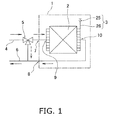
- FIG. 1 is a circuit diagram showing the convector and the circulation passage of a medium around the periphery of the convector.
- this convector 1 water (warm water or cold water) is circulated as a medium for transmitting heat.
- This convector 1 comprises a heat exchanger 2 for performing heat exchange between the circulated water and indoor air, and an air vent apparatus 3 for venting air from the circulation passage which circulates water through the heat exchanger 2.
- a feed tube 4 through which water flows from a chiller or another heat source (not shown) is connected to the inlet of a three-way valve 5.
- This three-way valve 5 has a first outlet for causing the incoming water to flow to the convector 1, and a second outlet for allowing the incoming water to flow to a feed tube 6 which returns water to the chiller or other heat source.
- the water that has exited the second outlet of the three-way valve 5 flows to the feed tube 6 without circulating through the convector 1.
- the convector 1 is provided with an inlet connection port 7 into which water flows before heat exchange, and an outlet connection port 8 from which water flows out after heat exchange.
- the water that has exited the first outlet of the three-way valve 5 flows into the convector 1 from the inlet connection port 7 of the convector 1.
- the inlet connection port 7 of the convector 1 is connected to an inlet header 9 of the heat exchanger 2, and the water flowing into the convector 1 is led to the heat exchanger 2. Water that has undergone heat exchange in the heat exchanger 2 is led from an outlet header 10 to the outlet connection port 8, and the water flows from the outlet connection port 8 to the feed tube 6.
- the air vent apparatus 3 for venting air from the water circulation passage as described above is configured such that a valve 25 is connected to the top part of the outlet header 10 by a capillary tube 26.
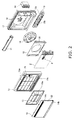
- the convector 1 comprises a front surface grill 12, an air filter 13, and an intake grill 14 which are superposed on the front of the heat exchanger 2 in the stated order from the side near the heat exchanger 2.
- a bell mouth 15 and a turbofan 16 are disposed in the stated order from the side near the heat exchanger 2
- a bottom frame 17 is disposed so as to cover the rear as well as the top, bottom, left, and right of the turbofan 16.
- a fan motor 18 for driving the turbofan 16 is attached along with a cover to the substantial center of the bottom frame 17 as seen from the front. Also attached to the bottom surface of the bottom frame 17 is an assembly 19 having a drain pan 19a for receiving condensed water forming in the heat exchanger 2 and a ventilation duct 19b of a bottom discharge port.
- An electrical components box 20 is attached to the inside surface of the bottom frame 17, and control of the rotational speed of the turbofan 16 and other factors is performed using a microcomputer housed inside the electrical components box 20. Power to the fan motor 18 and other internal devices is supplied from a power source line or the like leading to the electrical components box 20.
- an air direction adjuster 21 is attached to an opening 12a on the top of the grill so as to be capable of turning, and the ventilation duct 19b of the assembly 19 is attached to an opening 12b on the bottom of the grill.
- the opening 12a on the top of the front surface of the front surface grill 12 is connected with a top discharge port 14a of the intake grill 14, and the opening 12b on the bottom of the front surface is connected with a bottom discharge port 14b of the intake grill 14.
- An intake port 22 is provided to the side of the intake grill 14, and indoor air drawn in through this intake port 22 passes through the air filter 13 and the front surface grill 12 and flows to the heat exchanger 2.
- Conditioned air that has undergone heat exchange by passing through the heat exchanger 2 is blown out from a circular opening 23 in the bell mouth 15 toward the bottom frame 17 by the turbofan 16.
- the conditioned air that has reached the bottom frame 17 then runs into the bottom frame 17 to be blown out of the convector 1 through either the top discharge port 14a or the bottom discharge port 14b.
- the air vent apparatus 3 is attached to the upper right of the heat exchanger 2 as seen from the front surface. The details of the method for securing the air vent apparatus 3 are described hereinafter. Since the air vent apparatus 3 is provided to the front surface of the heat exchanger 2, the air vent apparatus 3 is exposed to the indoor air before heat exchange is performed in the heat exchanger 2.
- the air vent apparatus 3 and the air filter 13 are made to have a positional relationship such as the one previously described and are designed so that the air vent apparatus 3 does not come in contact with the air filter 13. Since the air vent apparatus 3 is arranged in this manner, a user can operate the air vent apparatus 3 by removing the intake grill 14 and the air filter 13.
- the intake grill 14 and the air filter 13 constitute a maintenance opening structure for exposing the openings 24 in the front surface of the heat exchanger 2 during maintenance.
- the water discharged from the air vent apparatus 3 when air venting is performed by the air vent apparatus 3 is discharged toward the heat exchanger 2.
- the structure is one in which the water flows along the front surface of the heat exchanger 2 and into the drain pan 19a from the heat exchanger 2. Because of this structure, there is no need for a hose for allowing the water to flow from the air vent apparatus 3 to the drain pan 19a as in conventional practice. Since the water during air venting flows along the front surface of the heat exchanger 2, the user (operator) can perceive that water has been drained appropriately by visually confirming that water is flowing.
- the air vent apparatus 3 To operate this manner of air venting, the user must turn an operating knob of the air vent apparatus 3 to open and close the valve. Therefore, the user may get injured by the fins of the heat exchanger 2.
- the air vent apparatus 3 is secured to the heat exchanger 2 by a plate-shaped securing implement, and this securing implement protects the user from injury.
- the air vent apparatus 3 directs the opening of the valve in the direction of the heat exchanger 2, and covers the front surface of the valve with the securing implement. With this type of configuration, the water that has exited the valve does not scatter in front of the valve, and water can be prevented from reaching the user.
- FIG. 3 is a partially cutaway front view of the heat exchanger to which the air vent apparatus is secured.
- FIG. 4 is a side view of the state of FIG. 3 as seen from the right.
- FIG. 5 is a cross-sectional view along line A-A of FIG. 3
- FIG. 6 is a cross-sectional view along line B-B of FIG. 3
- FIG. 7 is a cross-sectional view along line C-C of FIG. 3 .
- the air vent apparatus 3 is composed of the valve 25, the capillary tube 26, and a securing implement 27, as shown in FIG. 3 .
- the valve 25 has an external shape of a substantially hexagonal column, and has a nozzle 28 (see FIG. 7 ) and an operating knob 29.
- the valve 25 can be opened and closed by turning this operating knob 29 by hand.
- the capillary tube 26 connects the valve 25 with the top part of the outlet header 10 of the heat exchanger 2.
- the outlet header 10 has a linear portion 10a extending vertically, and air bubbles in the water flowing through the outlet header 10 collect in the top part of the outlet header 10.
- the valve 25 is opened, air is pushed by the water pressure of the outlet header 10 into the capillary tube 26 which is connected after narrowing gradually from the top part of the outlet header 10.
- the securing implement 27 has a base plate 30 formed by machining polypropylene into a plate shape, a fastener 31 provided on the front surface of the base plate 30 in order to fasten the valve 25, a pawl 32 provided to the base plate 30 in order to secure the base plate 30 to the heat exchanger 2, and a protective film 33 for protecting the capillary tube 26, as shown in FIG. 7 .
- the fastener 31 is composed of a clamping part 34 which is a portion for clamping the valve 25, a locking part 35 that locks so as to be able to keep the valve 25 in a clamped state by the clamping part 34, and a hinge 36 connecting the two portions of the clamping part 34 so that the clamping part 34 can be opened and closed.
- This fastener 31 is integrally molded from the same material as the base plate 30 made of polypropylene.
- the locking part 35 is composed of an opening provided to the extending portion of one of the two portions of the clamping part 34, and an insertion part having a pawl provided to the other extending portion, and locking can be achieved by inserting the insertion part through the opening and hooking the pawl on the periphery of the opening.
- the fastener 31 also functions as a cover for covering the periphery of the nozzle 28 of the valve 25. In other words, when the water discharged from the nozzle 28 scatters in a direction other than in the direction of the heat exchanger 2, the water is prevented from reaching the lower portion 37 or the like of the fastener 31 and scattering to the periphery of the fastener 31.
- a water-guiding plate 38 extends toward the heat exchanger 2 from the base plate 30.
- This water-guiding plate 38 is disposed so as to extend in front of the nozzle 28 of the valve 25 when the valve 25 has been fastened by the fastener 31.
- the water-guiding plate 38 is designed so that when the securing implement 27 is secured to the heat exchanger 2, the distal end of the water-guiding plate 38 is either in slight contact with the heat exchanger 2 or is disposed in a position facing the heat exchanger 2 across a slight gap. This type of design makes it possible for water whose force of discharge has been weakened by the water-guiding plate 38 to flow downward along the front surface of the heat exchanger 2.
- the distal end of the water-guiding plate 38 is disposed so as to be in contact with several fins 39 of the heat exchanger 2.
- the valve 25 By arranging the valve 25 in this manner, the water discharged when air is vented using the valve 25 runs along the front surfaces of the fins 39 of the heat exchanger 2, and the completion of the air venting operation can be confirmed by visually confirming this running water.
- the heat exchanger 2 is a cross-fin-coil type heat exchanger.
- a plurality of heat transfer tubes 40 extend parallel to each other and substantially horizontally, orthogonal to the long fins 39 extending up and down as shown in FIG. 6 .
- the securing implement 27 is secured by the pawl 32 provided on the rear surface thereof being fitted with the heat transfer tubes 40.
- the form in which the pawl 32 and the heat transfer tubes 40 fit together involves the pawl 32 being held between two heat transfer tubes 40 (the form shown in FIG. 6 ).
- the pawl 32 readily deforms in an elastic manner due to a cleft 32a being provided to part of the pawl 32, and the pawl 32 can be configured so as to be inserted smoothly between the heat transfer tubes 40.
- the securing implement 27 can be firmly secured so as to not move. Since the base plate 30 is made of a polypropylene plate about 2 mm thick, the configuration is thin but comparatively rigid, and the base plate 30 is not readily deformed by the operation of the valve 25 so as to move away from the heat exchanger 2.
- the capillary tube 26 connected to the valve 25 is disposed from the side surface of the heat exchanger 2 up to the front surface.
- the capillary tube 26 is bent in the periphery of the heat exchanger 2 and is pressed against the heat exchanger 2. Therefore, there is a possibility that the capillary tube 26 will be scratched by the edge of a tube plate 41 constituting the side surface of the heat exchanger 2 or by the fins 39 of the heat exchanger 2.
- the protective film 33 is attached to the right side of the base plate 30 of the securing implement 27, and this protective film 33 protects the capillary tube 26 from the fins 39 and the tube plate 41, as shown in FIG. 8 .
- the protective film 33 is configured from a thin film of polyethylene terephthalate in order to ensure a space for fitting the capillary tube 26.
- the protective film 33 is formed so as to bend in a substantial L shape when seen from the top surface, and is disposed not only on the front surface of the heat exchanger 2, but on the side surface of the heat exchanger 2 as well.
- the base plate 30 guards the fingers from touching the fins 39 when an operator grasps and turns the operating knob 29. Therefore, the base plate 30 spans a comparatively wide range behind the operating knob 29. A wider base plate 30 yields a greater effect of protecting the fingers of the operator.
- the base plate 30 since the base plate 30 is positioned on the front surface of the heat exchanger 2, i.e., upstream of the air flow passing through the heat exchanger 2, the base plate 30 hinders the flow of air flowing into the heat exchanger 2, and the heat exchange efficiency of the heat exchanger 2 therefore decreases when the surface area of the base plate 30 is increased.
- openings 30a, 30c not large enough to admit a finger are formed in the base plate 30, preventing the heat exchange efficiency of the heat exchanger 2 from decreasing.
- a large opening 30b is formed flanking the valve 25 on the opposite side from where the operating knob 29 is located because there is little likelihood of the fingers of the technician being inserted thereinto.
- FIG. 8 is a front view of the main body of the securing implement
- FIG. 9 is a rear view of the main body.
- the securing implement 27 is composed of the main body 27a which includes the base plate 30 made of polypropylene, the fastener 31, and the pawl 32; and an attachment 27b which includes the protective film 33 made of polyethylene terephthalate.
- the base plate 30 has a plurality of large and small openings 30a, 30b formed in a substantially rectangular plate having a width of approximately 160 mm and a height of approximately 55 mm.
- a secured-side member 34a of the clamping part 34 of the fastener 31 is disposed in the widthwise substantial center of the base plate 30.
- the clamping part 34 is composed of two portions, the secured-side member 34a and a turning-side member 34b, and these portions are connected by the hinge 36. Since the material of the main body 27a of the securing implement 27 is polypropylene, the hinge 36 is formed by providing a thin portion during the molding of the main body 27a.
- a thin-walled region 30j is also provided along an end edge 30E. The protective film 33 is attached to this thin-walled region 30j.
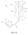
- FIG. 10 is a right-side view of the main body 27a of the securing implement 27.
- Concave parts 42a, 42b of the secured-side member 34a and the turning-side member 34b have the shape of a hexagon divided in two as shown in FIG. 10 , and when these two concave parts 42a, 42b are brought together, a space having a substantially hexagonal cross section is formed (see FIG. 15 ).
- ribs 47a, 47b shown in FIG. 12 fit in and secure the valve 25 so that the valve 25 does not come loose.
- the turning-side member 34b is rotated upward about the hinge 36 as an axis of rotation.
- FIG. 12 is a cross-sectiaxaal view along line D-D in FIG. 8 .
- An insertion part 43 and an opening 44 shown in FIG. 12 constitute the locking part 35.
- a pawl 43a is attached to the insertion part 43, and when the turning-side member 34b rotates and the insertion part 43 is inserted into the opening 44, the pawl 43a is brought in contact with the top part of the opening 44 and inserted therethrough while being pressed against the bottom side. Therefore, when the insertion part has been fully inserted, the pawl 43a locks on the opening 44 and the turning-side member 34b of the clamping part 34 is secured in place.
- a bulge 45 is formed in the concave part 42b as shown in FIG. 12 . Because of this bulge 45, the surface area of the space 34c, which is formed by joining together the two concave parts 42a, 42b and which has a hexagonal cross section, is smaller than the surface area of the cross section of the valve 25.
- the bulge 45 is pressed by the valve 25 and the turning-side member 34b of the clamping part 34 is lifted upward. The force by which the pawl 43a is caught in the opening 44 thereby increases, and the operator cannot remove the pawl 43a easily. It is thereby possible to prevent an adverse event in which the fastener 31 is displaced when the operator turns the operating knob 29.
- the valve 25 is also supported by a support plate 46 separated slightly from the fastener 31 so that the fastener 31 does not readily come out even if a twisting force acts on the valve 25 when the operating knob 29 is turned.
- the base plate 30 has a comparatively large protective area between the operating knob 29 and the fins 39 of the heat exchanger 2. If an operator is concerned that the fastener 31 might come out when the operating knob 29 is turned, the operator could also push the fastener 31 by hand. Therefore, the base plate 30 has a protective guard area 30m around the periphery of the fastener 31 even in the area where the operating knob 29 is not disposed.
- the protective guard area 30m of the base plate 30 is provided with openings 30a, 30c which allow air to pass through but do not allow fingers to pass through.
- the opening 30a is formed in the periphery of the valve 25, and is a small rectangular hole having a width of 5 mm and a height of 10 mm, for example. If the size of the opening 30a is as previously described, there is little chance of the fingers of an average adult passing through the opening 30a, and since the thickness of the base plate 30 is about 2 mm, for example, the operator need not give any thought to being injured unless the operator performs an unusual action such as intentionally pressing their fingers in the opening 30a.
- the opening 30c is even smaller than the opening 30a.
- a large opening 30b is formed in an area where the operator's fingers do not reach when performing air venting.
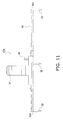
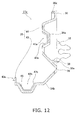
- pawls 32 are disposed at one end edge 30d and the other end edge 30e in the width direction of the base plate 30 as shown in FIGS. 11 and 14 , the base plate 30 readily flexes forward due to the force whereby the center of the base plate 30 is pulled to the front of the heat exchanger 2.
- a pawl 32 is also disposed on the back side of the fastener 31 as shown in FIGS. 11 and 14 . The pawl 32 on the back side of the fastener 31 prevents the base plate 30 from rising up off the front surface of the heat exchanger 2.
- the pawls 32 are also formed at different heights in the vertical direction, as is clear from FIG. 10 . When three pawls 32 are disposed in alignment at the same height, it is easier for three pawls 32 to rotate about an axis of a straight line joining the pawls.
- the pawls 32 are disposed as staggered in the vertical direction in order to prevent the securing implement 27 from being readily pulled out by this force in the rotational direction.
- the pawls 32 lock on the heat transfer tubes 40, as has already been described. Therefore, recessed portions 32b are formed in the edges of the pawls 32. Two heat transfer tubes 40 fit into the recessed portions 32b, whereby the securing implement 27 is secured to the front surface of the heat exchanger 2. The strength by which the pawls 32 fit with the heat transfer tubes 40 is adjusted by the cleft 32a so as not to be too firm. What secures the securing implement 27 in place is the three pawls 32 and the back surface of the base plate 30 being in contact with the heat transfer tubes 40 and fins 39 of the heat exchanger 2.
- the one of the three inner surfaces of the concave part 42a that is parallel to the base plate 30 is set apart from the base plate 30.
- the reason for such a structure is to direct the nozzle 28 of the valve 25 in the direction of the heat exchanger 2 but to prevent the nozzle 28 from coming in contact with the fins 39 of the heat exchanger 2 even when the valve 25 is fastened by the fastener 31.
- the nozzle 28 discharges water from the opening 31b of the fastener 31 (see FIGS. 9 and 12 ) toward the side of the heat exchanger 2.
- the nozzle 28 is not pointed horizontally toward the heat exchanger 2, but is inclined downward by about 60 degrees, for example, from the horizontal direction pointing at the heat exchanger 2. Therefore, the water-guiding plate 38 is positioned on the front surface of the nozzle 28.
- the water-guiding plate 38 is disposed horizontally in the state of the securing implement 27 being attached to the heat exchanger 2, and the top surface of the water-guiding plate 38 is angled at approximately 120 degrees, for example, in relation to a line extended from the nozzle 28. Therefore, water discharged from the nozzle 28 of the valve 25 strikes the water-guiding plate 38 and loses some of its discharge force, but this force causes the water to flow from the water-guiding plate 38 toward the front surface of the heat exchanger 2.
- the angle of the water-guiding plate 38 does not necessarily need to be horizontal. Whether the distal end 38a of the water-guiding plate 38 is pointed slightly upward or downward, the water is preferably led to the heat exchanger 2.
- the angle of the nozzle 28 is not limited to the angle described above, and is preferably directed toward the heat exchanger 2. The nozzle 28 is easily handled when pointed downward, however, because it is not preferable for the water exiting the nozzle 28 to return to the valve 25.
- the distal end 38a of the water-guiding plate 38 is in contact with the fins 39 of the heat exchanger 2.
- the water led to the distal end 38a of the water-guiding plate 38 has its discharge force weakened by the water-guiding plate 38, and the water therefore flows down over the front surfaces of the fins 39 into the lower drain pan 19a without going through the heat exchanger 2.
- the fins 39 fulfill the role of a hose, the hose can be omitted in the air vent apparatus 3 attached to the front surface of the heat exchanger 2. Since the water travels along the front surfaces of the fins 39, it is possible to confirm whether or not there is a discharge of exiting water after air has been vented, and it is possible to easily confirm that air has been vented in the air venting operation.
- ribs 30f, 30g are formed from one end edge 30d to the other end edge 30e. These intermittent horizontal ribs 30f and peaked ribs 30g are a result of the shapes of the openings 30a, 30b, 30c and the fastener 31.
- ribs 30f, 30g prevent some of the condensed water formed on the fins 39 of the heat exchanger 2 and other components from flowing forcefully over the front surface of the base plate 30 and dripping down from the base plate 30 so as to splash.
- the speed at which the condensed water heads downward is reduced.
- the condensed water thereby collects at the bottom end edge 30h of the base plate 30, and the condensed water again builds up to the fins 39 due to the surface tension of the collected condensed water. Since the fastener 31 projects from the base plate 30, the condensed water readily splashes when flowing over the top of the fastener 31.
- the ribs 30f, 30g be formed in the entire space between the one end edge 30d and the other end edge 30e of the base plate 30.
- the condensed water cannot get past the openings 30a, 30b, 30c, and the ribs 30f stop at the openings 30a, 30b, 30c.
- These ribs 30f, 30g are formed so as to project about several millimeters from the surface of the base plate 30. It has been found through experimentation that the position where the ribs 30f are formed is preferably higher than the vertical center.
- FIG. 13 is a cross-sectional view along line F-F in FIG. 8 .
- a lower part of the base plate 30 sticks out further as shown in FIG. 13 .
- the rigidity of the base plate 30 increases and the base plate 30 is stronger against bending stress.
- the base plate 30 is thereby prevented from being deformed by bending stress applied to the base plate 30 at times such as when the turning-side member 34b of the fastener 31 bends about the hinge 36 as an axis or when the operating knob 29 is turned.
- the attachment 27b is configured such that an adhesive material 50 is formed on the molded protective film 33.
- the adhesive material 50 is formed at a specified width along one lengthwise edge 33a of the substantially rectangular protective film 33.
- the protective film 33 and the adhesive material 50 can be molded by attaching double-sided tape at predetermined positions, for example, and perforating the protective film 33 together with the double-sided tape by Thompson processing.
- An opening 33c for positioning is also formed at the same time by perforating.
- An protrusion part 51 is formed in a location near the middle in the other lengthwise edge 33b opposite the lengthwise edge 33a.
- a folded part 52 provided above the protrusion part 51 is separated from the protrusion part 51 by a notch 53.
- the folded part 52 is formed by folding perpendicularly at the lengthwise edge 33b.
- the back surface of the folded part 52 is set on the front surface of the tube plate 41.
- the lengthwise edge 33b of the protective film 33 extends farther out than the back surface of the folded part 52 by a length L1 of about 0.5 mm, for example.
- the lengthwise edge 33b of the protective film 33 extends farther out than the corner of the tube plate 41 by the length L1, and there must therefore be a protective film 33 between the capillary tube 26 and the corner of the tube plate 41. Due to the presence of the protective film 33 on the corner of the tube plate 41, the capillary tube 26 is prevented from being scratched by the corner of the tube plate 41.
- the protective film 33 is configured from a thin material of about 0.5 mm, for example, even in cases in which the gaps between the components disposed on the front surface side of the heat exchanger 2 and the front surface of the heat exchanger 2 are the same small size as in conventional practice, the capillary tube 26 can be drawn to the front surface of the heat exchanger 2 if the gap is slightly larger than the diameter of the capillary tube 26.
- FIGS. 18 and 19 show a state in which the attachment 27b has been attached to the main body 27a.
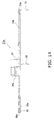
- FIG. 18 is a rear side view of the securing implement 27, and
- FIG. 19 is a plan view of the securing implement 27.
- the protective film 33 is attached to the thin-walled region 30j of the base plate 30 (see FIG. 9 ). Since the protective film 33 is secured to the thin-walled region 30j, the back surface of the securing implement 27 is coplanar with the back surface of the base plate 30 and the protective film 33 even if the protective film 33 is thick. Therefore, the entire back side of the securing implement 27 including the protective film 33 and the back surface of the base plate 30 can be brought in contact with the fins 39.
- the protective film 33 is positioned relative to the base plate 30 by fitting a pawl 32 into the opening 33c. Because of this pawl 32, the protective film does not come off even if the protective film 33 is pulled with the protrusion part 51.
- the convector 1 (heat exchange unit) comprises the air vent apparatus 3 for venting air entering the circulation passage of the heat exchanger 2.
- the air vent apparatus 3 is attached to the front surface of the heat exchanger 2.
- the openings 24 of the front surface grill 12 on the front surface of the heat exchanger 2 can be exposed during maintenance of the heat exchanger 2 in order to perform maintenance on the heat exchanger 2.
- the operating knob 29 of the valve 25 of the air vent apparatus 3 can be turned through the openings 24 to perform air venting.
- the openings 24 of the front surface grill 12 can be exposed by removing the intake grill 14 and the air filter 13 which are attached to the convector 1 so as to be removable.
- the intake grill 14 and the air filter 13 capable of being removed constitute a maintenance opening structure.
- the maintenance opening structure herein is preferably one in which the opening in the front surface of the heat exchanger 2 is exposed in order to perform maintenance on the heat exchanger 2, and the structure does not necessarily need to be removable.
- This maintenance opening structure is contained in a casing that includes the front surface grill 12 to which the intake grill 14 and air filter 13 are attached.
- valve 25 of the air vent apparatus 3 located on the front surface of the heat exchanger 2, the valve 25 is easily exposed in order to perform the air venting operation.
- adverse events of the valve 25 being mistakenly opened can be prevented because the valve 25 is covered by the intake grill 14 and the air filter 13.
- the air vent apparatus 3 branches off from the circulation passage as shown in FIG. 1 , the water in the capillary tube 26 of the air vent apparatus 3 is not circulated, the effect of the air vent apparatus 3 being cooled by the water is therefore small, and there is no condensation.
- the air vent apparatus 3 is disposed on the front surface of the heat exchanger 2, indoor air is constantly blowing over the air vent apparatus 3 and acting so as to dry the air vent apparatus 3, and the air vent apparatus 3 therefore has a configuration even more resistant to condensation.
- the ribs 30f, 30g are provided in order to ensure that the condensed water flowing down to the base plate 30 of the securing implement 27 from the heat exchanger 2 does not scatter.
- the ribs 30f, 30g are cut off at the locations of the openings 30a, 30b, 30c and other obstacles, but are disposed so as to extend from one of the end edges 30d, 30e to the other, which face each other horizontally. This is because water that passes over the front surface of the base plate 30 must make contact with the ribs 30f, 30g.
- the fastener 31 (holding part) of the securing implement 27 holds the nozzle 28 of the valve 25 in a direction pointing toward the heat exchanger 2. Therefore, when the air venting operation is performed, water exiting the nozzle 28 is discharged onto the heat exchanger 2. The water flows over the fins 39 of the heat exchanger 2 and is led to the drain pan 19a. With this type of configuration, water is led to the drain pan 19a without a hose leading from the nozzle 28 to the drain pan 19a. The hose can be omitted by using this type of configuration.
- the hose Since the hose is omitted and the tip of the nozzle 28 is opened, it is thus possible for water exiting the nozzle 28 to drip down from the nozzle 28.
- the water-guiding plate 38 is provided to the securing implement 27, and the water discharged from the nozzle 28 is led to the fins 39 of the heat exchanger 2 by the water-guiding plate 38.
- the nozzle 28 is secured in place in a position whereby the flow of water exiting the nozzle 28 can reach the heat exchanger 2.
- the capillary tube 26 of the air vent apparatus 3 Since the capillary tube 26 of the air vent apparatus 3 is connected to the outlet header 10 of the heat exchanger 2, the water in the capillary tube 26 is subjected to pressure for circulating the water.
- the valve 25 When the valve 25 is opened in such a state, water is forcefully expelled out of the nozzle 28. Therefore, merely by having the nozzle 28 directed toward the heat exchanger 2, water exiting the nozzle 28 can penetrate, and manage to enter the back surface of, the heat exchanger 2.
- the water-guiding plate 38 is disposed in a direction facing the nozzle 28 so that the water does not penetrate the heat exchanger 2.
- the water-guiding plate 38 functions as a force reducer, serving to weaken the force of the water exiting the nozzle 28.
- the force of the water weakened and the water exiting the nozzle 28 directed to the front surface of the heat exchanger 2 the water flows over the front surface of the heat exchanger 2. Since an operation is performed for draining water from the openings 24 in the front surface of the heat exchanger 2, the operator can visually confirm the water flowing over the front surface of the heat exchanger 2 in this manner and can confirm that the water draining operation has ended by visually confirming the water flowing over the heat exchanger 2.
- the nozzle 28 is covered by the fastener 31 except for the portion in the direction in which the distal end of the nozzle 28 points.
- the fastener 31 fulfills the role of a cover. Water (the medium) can thereby be prevented from getting on the body, hands, or feet of the operator during the operation.
- the clamping part 34 clamps the valve 25, but the fastener 31 is caught by the locking part 35 in order to maintain the clamped state.
- the clamping part 34 attempts to clamp the valve 25 over a smaller surface area than the cross-sectional surface area of the valve 25 because of the bulge 45. Therefore, the turning-side member 34b is raised upward, the force by which the pawl 43a is caught in the locking part 35 is maximized, the resistance against the pulling force increases, and it is therefore possible to prevent the hold of the fastener 31 (holding part) from being released by the operator opening and closing the valve.
- the securing implement 27 is secured to the heat transfer tubes 40 of the heat exchanger 2 by three pawls 32 (fitting parts). Each of the pawls 32 is insertably fitted between two heat transfer tubes 40. Since the securing implement 27 is secured in place by the pawls 32 alone, the configuration of the securing implement 27 is extremely simple. Therefore, the pawls 32 can be created together with the other portions of the main body 27a of the securing implement 27 by plastic integrated molding, and it is possible to provide the securing implement 27 having fitting parts at low cost. Merely having the pawls 32 fitted simplifies the operation, and facilitates the securing task of the securing implement 27.
- Each of the pawls 32 herein is fitted in between two heat transfer tubes 40, but the fitting can also be accomplished by pawls that clamp one heat transfer tube 40.
- One heat transfer tube 40 may be inserted in a cleft 32a of a pawl having a shape such as that of the pawls 32, a portion 32b recessed in the edge may be inserted between two heat transfer tubes on both side and secured in place to three heat transfer tubes 40, and the number of heat transfer tubes 40 fitted with one pawl can be selected appropriately.
- another possibility is to clamp and fasten the heat transfer tubes with something having a different shape than the pawls; e.g., something with a shape such as that of the fastener 31.
- the operating knob 29 is turned to open and close the valve 25.
- the securing implement 27 has a guard area 30m where the base plate 30 extends around the periphery of the operating knob 29.
- the openings 30a, 30c in the guard area 30m are too small for fingers to fit through. Therefore, the guard area 30m prevents fingers from being scratched by the fins 39 of the heat exchanger 2.
- the openings 30a, 30c allow air to pass through to the heat exchanger 2 and therefore have the effect of preventing a decrease in heat exchange efficiency in the heat exchanger 2.
- the guard area 30m also extends in the periphery of the fastener 31 and can also protect fingers holding the fastener 31.
- the valve 25 and the outlet header 10 of the circulation passage of the heat exchanger 2 are connected by the capillary tube 26. Since the outlet header 10 is disposed on the side surface of the heat exchanger 2 and the valve 25 is disposed on the front surface of the heat exchanger, the capillary tube 26 is drawn around the heat exchanger 2 from the side surface to the front surface. Because the capillary tube 26 is arranged in this manner, the protective film 33 is disposed between the capillary tube 26 and the heat exchanger 2.
- the protective film 33 fulfills the role of protecting the capillary tube 26 so that the capillary tube 26 is not scratched by the fins 39 or the tube plate 41 of the heat exchanger 2.
- the reason the protective film 33 is configured from a material thinner than the base plate 30 of the securing implement 27 is because there is only a small space in the peripheral edge of the side surface of the heat exchanger 2 and it is therefore difficult to place a thick member such as the base plate 30.
Landscapes
- Engineering & Computer Science (AREA)
- Mechanical Engineering (AREA)
- General Engineering & Computer Science (AREA)
- Physics & Mathematics (AREA)
- Thermal Sciences (AREA)
- Chemical & Material Sciences (AREA)
- Combustion & Propulsion (AREA)
- Other Air-Conditioning Systems (AREA)
- Heat-Exchange Devices With Radiators And Conduit Assemblies (AREA)
Abstract
Description
- The present invention relates to an air vent apparatus, a heat exchange unit, and a securing implement of an air vent apparatus; and particularly relates to an air vent apparatus for venting the air of a circulation passage of a heat exchanger, a heat exchange unit, and a securing implement.
- An air vent apparatus used to vent air in a circulation passage of a heat exchanger is provided inside an air conditioner or another heat exchange unit comprising a heat exchanger, as disclosed in Patent Literature 1 (Japanese Unexamined Utility Model Application Publication No.
2-77511 - However, air bubbles sometimes form in the circulation passage after installation, and these air bubbles are sometimes the cause of abnormal noises. In such cases, if the user can perform air venting, the technician does not need to go through the trouble of performing air venting and can make repairs easily.
- An object of the present invention is to provide an air vent apparatus whereby a user can easily perform air venting when air bubbles have formed in the circulation passage of the heat exchanger, a heat exchange unit comprising the air vent apparatus, and a securing implement applied to this type of air vent apparatus.
- A heat exchange unit according to a first aspect of the present invention is a heat exchange unit for performing heat exchange between air and a medium circulating through a circulation passage, the heat exchange unit comprising a heat exchanger, a casing, and a valve. The heat exchanger is connected to the circulation passage. The casing covers the front surface of the heat exchanger. The casing has a maintenance opening structure for exposing an opening in the front surface of the heat exchanger during maintenance. The valve is connected to the circulation passage. The valve is disposed in the front surface of the heat exchanger facing the opening of the casing.
- In the heat exchange unit according to the first aspect of the present invention, the valve is disposed on the front surface of the heat exchanger and in a position facing the opening of the casing. During maintenance of the heat exchanger, the opening can be exposed by the maintenance opening structure. A user can insert their hand through this opening, for example, to open the valve and perform air venting. Therefore, the user of the heat exchange unit can open the valve and easily perform the operation for performing air venting by the same procedure as the maintenance of the heat exchanger, without removing the cover over the entire unit or the components inside the internal unit as in conventional practice.
- A heat exchange unit according to a second aspect of the present invention is the heat exchange unit according to the first aspect, wherein the valve has a nozzle for venting air. The heat exchange unit further comprises a securing implement. The securing implement secures the valve in place on the front surface of the heat exchanger. Therefore, the securing implement has a holding part for holding the nozzle of the valve in an orientation pointed toward the heat exchanger.
- In the heat exchange unit according to the second aspect of the present invention, since the nozzle of the valve is held in an orientation pointed toward the heat exchanger by the holding part of the securing implement, the medium discharged from the nozzle strikes the heat exchanger, flows over the heat exchanger, and can be led to a drain pan provided for the heat exchanger. A hose for causing the medium to flow from the nozzle to the drain pan can thereby be omitted.
- A heat exchange unit according to a third aspect of the present invention is the heat exchange unit according to the first aspect, wherein the securing implement further has, in front of the nozzle, a force reducer for weakening the force of the medium discharged from the nozzle of the valve.
- With the heat exchange unit according to the third aspect of the present invention, the force of the medium discharged from the nozzle of the valve is weakened by the force reducer, whereby the medium is no longer scattered deep into the heat exchanger, and the medium can be led downward along the front surface of the heat exchanger. Since the force of the medium exiting the nozzle is weakened, the medium can be prevented from hitting the heat exchanger and splashing during the air venting operation.
- A heat exchange unit according to a fourth aspect of the present invention is the heat exchange unit according to the second or third aspect, wherein the heat exchanger has a heat transfer tube for causing the medium to flow into the interior, whereby the heat of the medium is transmitted. The securing implement further has a fitting part that fits with the heat transfer tube of the heat exchanger in order to secure the securing implement to the heat exchanger.
- With the heat exchange unit according to the fourth aspect of the present invention, since the fitting part is fitted with the heat transfer tube, the securing implement is directly secured to the heat exchanger, the positional relationship between the securing implement and the heat exchanger is easily set, and the structure of the securing implement can be simplified.
- A heat exchange unit according to a fifth aspect of the present invention is the heat exchange unit according to the second or third aspect, wherein the valve has an operating knob for opening and closing the valve. The securing implement further has a base plate. The base plate is provided with a holding part. Furthermore, the base plate has a guard region which extends in the space between the operating knob and the heat exchanger in a state in which the valve is held in the holding part.
- With the heat exchange unit according to the fifth aspect of the present invention, the guard area held by the base plate between the operating knob and the heat exchanger provides the effect of impeding any fingers turning the operating knob from coming in contact with the heat exchanger.
- A heat exchange unit according to a sixth aspect of the present invention is the heat exchange unit according to any of the second through fifth aspects, further comprising a tube connecting the circulation passage and the valve. The securing implement further has a protective film for protecting the tube from the heat exchanger, the protective film being disposed between the tube and the heat exchanger.
- With the heat exchange unit according to the sixth aspect of the present invention, the tube can be prevented from coming in contact with a location of the heat exchanger where the tube is easily scratched, by the protective film disposed between the tube and the heat exchanger.
- A heat exchange unit according to a seventh aspect of the present invention is the heat exchange unit according to the second or third aspect, wherein the securing implement further has a cover for covering a periphery of the nozzle of the valve in a state in which the valve is held in the holding part.
- With the heat exchange unit according to the seventh aspect of the present invention, the splashing of the medium scattering around the periphery of the nozzle is blocked by the cover, and the medium does not scatter past the cover.
- A heat exchange unit according to an eighth aspect of the present invention is the heat exchange unit according to the second aspect, wherein the holding part has a clamping part for clamping the valve, and a locking part for immobilizing the clamping part in order to keep the valve in a state of being clamped by the clamping part. The holding part includes a valve-clamping area. The valve-clamping area formed when the clamping part is immobilized by the locking part includes a portion smaller than the external shape of the valve.
- With the heat exchange unit according to the eighth aspect of the present invention, when an attempt is made to clamp the valve with a portion smaller than the external shape of the valve, the clamping part is pushed by the valve and therefore rises, the locking force of the locking part is maximized, the clamping part is firmly caught by the locking part, and therefore, does not come loose easily.
- A heat exchange unit according to a ninth aspect of the present invention is the heat exchange unit according to any of the second through eighth aspects, wherein the securing implement secures the nozzle in place at a position where the medium discharged from the nozzle flows over the front surface of the heat exchanger.
- With the heat exchange unit according to the ninth aspect of the present invention, the medium can be led downward along the front surface of the heat exchanger due to the secured location of the nozzle.
- A heat exchange unit according to a tenth aspect of the present invention is the heat exchange unit according to the fifth aspect, wherein the base plate has on a front surface a rib extending from one end edge to another end edge that face each other horizontally.
- With the heat exchange unit according to the tenth aspect, condensed water flowing over the surface of the base plate must flow over the rib, and the speed at which the condensed water flows therefore decreases. The condensed water thereby no longer forcefully flows over the surface of the base plate of the securing implement or forcefully drips down from the base plate.
- An air vent apparatus according to an eleventh aspect of the present invention is an air vent apparatus for venting air entering a circulation passage of a heat exchanger, the air vent apparatus comprising a valve and a securing implement. The valve is connected to the circulation passage. The securing implement is used to secure the valve to a front surface of the heat exchanger that draws in air.
- With the air vent apparatus according to the eleventh aspect of the present invention, the valve is secured in place to the front side of the heat exchanger. The unit housing the heat exchanger is often configured so that in the front surface of the heat exchanger, the covers can be removed and the hand can be inserted through the front surface in order to maintain the heat exchanger. Therefore, when the valve is secured in place on the front surface of the heat exchanger, if the covers of the heat exchanger are removed by the same procedure as that used to maintain the heat exchanger, the valve of the air vent apparatus can be opened to perform the air venting operation, even if the covers over the entire unit or the members inside the unit are not removed as in conventional practice.
- An air vent apparatus according to a twelfth aspect of the present invention is the air vent apparatus according to the eleventh aspect, wherein the valve has a nozzle for venting air. The securing implement has a holding part for holding the nozzle of the valve in an orientation pointed toward the heat exchanger.
- With the air vent apparatus according to the twelfth aspect of the present invention, since the nozzle of the valve is held in an orientation pointed toward the heat exchanger by the holding part of the securing implement, the medium exiting the nozzle of the valve can be led to the drain pan provided for the heat exchanger. A hose for causing the medium to flow from the nozzle to the drain pan can therefore be omitted.
- A securing implement according to a thirteenth aspect of the present invention is a securing implement of an air vent apparatus for venting air entering a circulation passage of a heat exchanger, the securing implement comprising a base plate and a holding part. The holding part is provided to a front surface of the base plate. The holding part holds the air vent apparatus in the front surface of the base plate so that a nozzle of the air vent apparatus is oriented toward the heat exchanger.
- With the securing implement according to the thirteenth aspect of the present invention, the valve is secured in place to the front surface of the heat exchanger. The unit housing the heat exchanger is often configured so that in the front surface of the heat exchanger, the covers can be removed and the hand can be inserted through the front surface in order to maintain the heat exchanger. Therefore, if the covers of the heat exchanger are removed by the same procedure as that of maintenance of the heat exchanger, the valve of the air vent apparatus can be opened to perform the air venting operation, even if the covers over the entire unit or the members inside the unit are not removed as in conventional practice.
- Since the nozzle of the valve is also held in an orientation pointed toward the heat exchanger by the holding part, the medium exiting the nozzle of the valve can be led to the drain pan provided for the heat exchanger. A hose for causing the medium to flow from the nozzle to the drain pan can therefore be omitted.
- A securing implement according to a fourteenth aspect of the present invention is the securing implement according to the thirteenth aspect, further comprising a fitting part that fits with the heat transfer tube of the heat exchanger, the fitting part being provided to a rear surface of the base plate.
- With the heat exchange unit according to the fourteenth aspect of the present invention, since the fitting part is fitted with the heat transfer tube, the securing implement can be secured directly in place to the heat exchanger, the positional relationship between the securing implement and the heat exchanger is easily set, and the structure of the securing implement can be simplified.
- With the heat exchange unit according to the first aspect of the present invention, air venting can be performed by a simple procedure that is no different from that when performing maintenance of the heat exchanger, and the user of the heat exchange unit can enact the air venting operation in a simple manner without relying on the installation technician. In addition, when air venting is not being performed, adverse events in which the user mistakenly operates the valve can be prevented because the valve is also covered in the same manner as the heat exchanger.
- With the heat exchange unit according to the second aspect of the present invention, the hose or the like connecting to the nozzle of the valve is omitted, the air vent apparatus can therefore be configured at low cost, and the heat exchange unit can be made more compact.
- With the heat exchange unit according to the third aspect of the present invention, since the medium exiting the nozzle flows over the front surface of the heat exchanger, it is possible to easily confirm that air venting is complete and the medium is coming out, and the air venting operation is simplified.
- With the heat exchange unit according to the fourth aspect of the present invention, not only is the securing implement made less expensive by the simplification of the securing implement, but attaching the securing implement is also simplified, and the manufacturing cost of the heat exchange unit can be reduced.
- With the heat exchange unit according to the fifth aspect of the present invention, safety can be improved because the base plate impedes any fingers turning the operating knob from coming in contact with the heat exchanger.
- With the heat exchange unit according to the sixth aspect of the present invention, the protective film can prevent the tube from being scratched by the fins or tube plate of the heat exchanger.
- With the heat exchange unit according to the seventh aspect of the present invention, the cover prevents the medium from getting on the technician performing air venting during the air venting operation.
- With the heat exchange unit according to the eighth aspect of the present invention, secure locking can be provided by the locking part, making it possible to prevent adverse events in which the holding part is released due to the force acting on the operating knob when the operating knob is being operated.
- With the heat exchange unit according to the ninth aspect of the present invention, since the medium exiting the valve flows over the front surface of the heat exchanger, it is possible to easily confirm that air venting is complete and the medium is coming out, and the air venting operation is simplified.
- With the heat exchange unit according to the tenth aspect of the present invention, the base plate of the securing implement can prevent the condensed water of the heat exchanger from splashing.
- With the air vent apparatus according to the eleventh aspect of the present invention, air venting can be performed with a simple procedure no different from that employed to perform maintenance of the heat exchanger, and the user of the devices housed within the heat exchanger can perform the air venting operation in a simple manner without relying on an installation technician. On the other hand, when air venting is not being performed, the air vent apparatus is covered by the cover in the same manner as the heat exchanger, and adverse events in which the user mistakenly operates the air vent apparatus can therefore be prevented.
- With the air vent apparatus according to the twelfth aspect of the present invention, since the hose or other component connecting to the nozzle of the valve is omitted, the air vent apparatus can be configured at low cost, and the air vent apparatus can be made more compact.
- With the securing implement according to the thirteenth aspect of the present invention, air venting can be performed with a simple procedure no different from that employed to perform maintenance of the heat exchanger, and the user of the devices housed within the heat exchanger can perform the air venting operation in a simple manner without relying on an installation technician. On the other hand, when air venting is not being performed, the air vent apparatus is covered by the cover in the same manner as the heat exchanger, and adverse events in which the user mistakenly operates the air vent apparatus can therefore be prevented.
- Since the hose or other component connecting to the nozzle of the valve is also omitted, the air vent apparatus can be configured at low cost, and the air vent apparatus can be made more compact.
- With the heat exchange unit according to the fourteenth aspect of the present invention, it is possible to provide an easily attached securing implement at low cost by simplifying the securing implement.
-
-
FIG. 1 is a circuit diagram showing part of a circuit to which a heat exchange unit according to an embodiment of the present invention is connected. -
FIG. 2 is an exploded perspective view of the heat exchange unit ofFIG. 1 . -
FIG. 3 is a front view of a heat exchanger housed inside the heat exchange unit ofFIG. 2 . -
FIG. 4 is a side view of the heat exchanger shown inFIG. 3 . -
FIG. 5 is a cross-sectional view along line A-A ofFIG. 3 . -
FIG. 6 is a cross-sectional view along line B-B ofFIG. 3 . -
FIG. 7 is a cross-sectional view along line C-C ofFUG 3. -
FIG. 8 is a front view of the main body of a securing implement. -
FIG. 9 is a rear view of the main body shown inFIG. 8 . -
FIG. 10 is a side view of the main body shown in PIG. 8. -
FIG. 11 is a plan view of the main body shown inFIG. 8 . -
FIG. 12 is a cross-sectional view along line D-D ofFIG. 8 . -
FIG. 13 is a cross-sectional view along line E-E ofFIG. 8 . -
FIG. 14 is a cross-sectional view along line F-F ofFIG. 8 . -
FIG. 15 is a cross-sectional view showing a state in which a clamping part of the main body shown inFIG. 12 is closed. -
FIG. 16 is a front view of an attachment of the securing implement. -
FIG. 17 is a side view of the attachment shown inFIG. 16 . -
FIG. 18 is a rear view of the securing implement wherein the main body ofFIG. 8 and the attachment ofFIG. 16 have been assembled. -
FIG. 19 is a plan view of the securing implement ofFIG. 18 . - A convector as a heat exchange unit according to an embodiment of the present invention is described hereinbelow. The following descriptions are made in the order of the circulation passage of the convector, the structure of the convector, the configuration and securing of an air vent apparatus housed inside the convector, and a securing implement of the air vent apparatus.
-
FIG. 1 is a circuit diagram showing the convector and the circulation passage of a medium around the periphery of the convector. In this convector 1, water (warm water or cold water) is circulated as a medium for transmitting heat. This convector 1 comprises aheat exchanger 2 for performing heat exchange between the circulated water and indoor air, and anair vent apparatus 3 for venting air from the circulation passage which circulates water through theheat exchanger 2. - A
feed tube 4 through which water flows from a chiller or another heat source (not shown) is connected to the inlet of a three-way valve 5. This three-way valve 5 has a first outlet for causing the incoming water to flow to the convector 1, and a second outlet for allowing the incoming water to flow to afeed tube 6 which returns water to the chiller or other heat source. The water that has exited the second outlet of the three-way valve 5 flows to thefeed tube 6 without circulating through the convector 1. - The convector 1 is provided with an inlet connection port 7 into which water flows before heat exchange, and an
outlet connection port 8 from which water flows out after heat exchange. The water that has exited the first outlet of the three-way valve 5 flows into the convector 1 from the inlet connection port 7 of the convector 1. The inlet connection port 7 of the convector 1 is connected to aninlet header 9 of theheat exchanger 2, and the water flowing into the convector 1 is led to theheat exchanger 2. Water that has undergone heat exchange in theheat exchanger 2 is led from anoutlet header 10 to theoutlet connection port 8, and the water flows from theoutlet connection port 8 to thefeed tube 6. - The
air vent apparatus 3 for venting air from the water circulation passage as described above is configured such that avalve 25 is connected to the top part of theoutlet header 10 by acapillary tube 26. - The structure of the convector 1 to which the
air vent apparatus 3 is secured is described using the exploded perspective view ofFIG. 2 . The convector 1 comprises afront surface grill 12, anair filter 13, and anintake grill 14 which are superposed on the front of theheat exchanger 2 in the stated order from the side near theheat exchanger 2. Behind theheat exchanger 2, abell mouth 15 and aturbofan 16 are disposed in the stated order from the side near theheat exchanger 2, and abottom frame 17 is disposed so as to cover the rear as well as the top, bottom, left, and right of theturbofan 16. - A
fan motor 18 for driving theturbofan 16 is attached along with a cover to the substantial center of thebottom frame 17 as seen from the front. Also attached to the bottom surface of thebottom frame 17 is anassembly 19 having adrain pan 19a for receiving condensed water forming in theheat exchanger 2 and aventilation duct 19b of a bottom discharge port. Anelectrical components box 20 is attached to the inside surface of thebottom frame 17, and control of the rotational speed of theturbofan 16 and other factors is performed using a microcomputer housed inside theelectrical components box 20. Power to thefan motor 18 and other internal devices is supplied from a power source line or the like leading to theelectrical components box 20. - In the
front surface grill 12, anair direction adjuster 21 is attached to anopening 12a on the top of the grill so as to be capable of turning, and theventilation duct 19b of theassembly 19 is attached to anopening 12b on the bottom of the grill. Theopening 12a on the top of the front surface of thefront surface grill 12 is connected with atop discharge port 14a of theintake grill 14, and theopening 12b on the bottom of the front surface is connected with abottom discharge port 14b of theintake grill 14. Anintake port 22 is provided to the side of theintake grill 14, and indoor air drawn in through thisintake port 22 passes through theair filter 13 and thefront surface grill 12 and flows to theheat exchanger 2. Conditioned air that has undergone heat exchange by passing through theheat exchanger 2 is blown out from acircular opening 23 in thebell mouth 15 toward thebottom frame 17 by theturbofan 16. The conditioned air that has reached thebottom frame 17 then runs into thebottom frame 17 to be blown out of the convector 1 through either thetop discharge port 14a or thebottom discharge port 14b. - The
air vent apparatus 3 is attached to the upper right of theheat exchanger 2 as seen from the front surface. The details of the method for securing theair vent apparatus 3 are described hereinafter. Since theair vent apparatus 3 is provided to the front surface of theheat exchanger 2, theair vent apparatus 3 is exposed to the indoor air before heat exchange is performed in theheat exchanger 2. - The
air vent apparatus 3 secured to the front surface of theheat exchanger 2 protrudes forward throughopenings 24 in the lattice of thefront surface grill 12. Therefore, the periphery of the valve, which is the portion of theair vent apparatus 3 that protrudes the farthest, is disposed in a location near the center so as to overlap aportion 13a of theair filter 13 that protrudes forward in a front view. Theair vent apparatus 3 and theair filter 13 are made to have a positional relationship such as the one previously described and are designed so that theair vent apparatus 3 does not come in contact with theair filter 13. Since theair vent apparatus 3 is arranged in this manner, a user can operate theair vent apparatus 3 by removing theintake grill 14 and theair filter 13. - In other words, the
intake grill 14 and theair filter 13 constitute a maintenance opening structure for exposing theopenings 24 in the front surface of theheat exchanger 2 during maintenance. - The water discharged from the
air vent apparatus 3 when air venting is performed by theair vent apparatus 3 is discharged toward theheat exchanger 2. The structure is one in which the water flows along the front surface of theheat exchanger 2 and into thedrain pan 19a from theheat exchanger 2. Because of this structure, there is no need for a hose for allowing the water to flow from theair vent apparatus 3 to thedrain pan 19a as in conventional practice. Since the water during air venting flows along the front surface of theheat exchanger 2, the user (operator) can perceive that water has been drained appropriately by visually confirming that water is flowing. - To operate this manner of air venting, the user must turn an operating knob of the
air vent apparatus 3 to open and close the valve. Therefore, the user may get injured by the fins of theheat exchanger 2. In view of this, theair vent apparatus 3 is secured to theheat exchanger 2 by a plate-shaped securing implement, and this securing implement protects the user from injury. Theair vent apparatus 3 directs the opening of the valve in the direction of theheat exchanger 2, and covers the front surface of the valve with the securing implement. With this type of configuration, the water that has exited the valve does not scatter in front of the valve, and water can be prevented from reaching the user. - Next, the configuration and method for securing the air vent apparatus will be described using
FIGS. 3 through 7 .FIG. 3 is a partially cutaway front view of the heat exchanger to which the air vent apparatus is secured.FIG. 4 is a side view of the state ofFIG. 3 as seen from the right.FIG. 5 is a cross-sectional view along line A-A ofFIG. 3 ,FIG. 6 is a cross-sectional view along line B-B ofFIG. 3 , andFIG. 7 is a cross-sectional view along line C-C ofFIG. 3 . - The
air vent apparatus 3 is composed of thevalve 25, thecapillary tube 26, and a securing implement 27, as shown inFIG. 3 . Thevalve 25 has an external shape of a substantially hexagonal column, and has a nozzle 28 (seeFIG. 7 ) and an operatingknob 29. Thevalve 25 can be opened and closed by turning this operatingknob 29 by hand. - As can be seen from
FIGS. 3 and4 et al., thecapillary tube 26 connects thevalve 25 with the top part of theoutlet header 10 of theheat exchanger 2. Theoutlet header 10 has alinear portion 10a extending vertically, and air bubbles in the water flowing through theoutlet header 10 collect in the top part of theoutlet header 10. When thevalve 25 is opened, air is pushed by the water pressure of theoutlet header 10 into thecapillary tube 26 which is connected after narrowing gradually from the top part of theoutlet header 10. - The securing implement 27 has a
base plate 30 formed by machining polypropylene into a plate shape, afastener 31 provided on the front surface of thebase plate 30 in order to fasten thevalve 25, apawl 32 provided to thebase plate 30 in order to secure thebase plate 30 to theheat exchanger 2, and aprotective film 33 for protecting thecapillary tube 26, as shown inFIG. 7 . - The
fastener 31 is composed of a clampingpart 34 which is a portion for clamping thevalve 25, a lockingpart 35 that locks so as to be able to keep thevalve 25 in a clamped state by the clampingpart 34, and ahinge 36 connecting the two portions of the clampingpart 34 so that the clampingpart 34 can be opened and closed. Thisfastener 31 is integrally molded from the same material as thebase plate 30 made of polypropylene. The lockingpart 35 is composed of an opening provided to the extending portion of one of the two portions of the clampingpart 34, and an insertion part having a pawl provided to the other extending portion, and locking can be achieved by inserting the insertion part through the opening and hooking the pawl on the periphery of the opening. - The
fastener 31 also functions as a cover for covering the periphery of thenozzle 28 of thevalve 25. In other words, when the water discharged from thenozzle 28 scatters in a direction other than in the direction of theheat exchanger 2, the water is prevented from reaching thelower portion 37 or the like of thefastener 31 and scattering to the periphery of thefastener 31. - Furthermore, a water-guiding
plate 38 extends toward theheat exchanger 2 from thebase plate 30. This water-guidingplate 38 is disposed so as to extend in front of thenozzle 28 of thevalve 25 when thevalve 25 has been fastened by thefastener 31. The water-guidingplate 38 is designed so that when the securing implement 27 is secured to theheat exchanger 2, the distal end of the water-guidingplate 38 is either in slight contact with theheat exchanger 2 or is disposed in a position facing theheat exchanger 2 across a slight gap. This type of design makes it possible for water whose force of discharge has been weakened by the water-guidingplate 38 to flow downward along the front surface of theheat exchanger 2. To achieve this, the distal end of the water-guidingplate 38 is disposed so as to be in contact withseveral fins 39 of theheat exchanger 2. By arranging thevalve 25 in this manner, the water discharged when air is vented using thevalve 25 runs along the front surfaces of thefins 39 of theheat exchanger 2, and the completion of the air venting operation can be confirmed by visually confirming this running water. - The
heat exchanger 2 is a cross-fin-coil type heat exchanger. In this type ofheat exchanger 2, a plurality ofheat transfer tubes 40 extend parallel to each other and substantially horizontally, orthogonal to thelong fins 39 extending up and down as shown inFIG. 6 . The securing implement 27 is secured by thepawl 32 provided on the rear surface thereof being fitted with theheat transfer tubes 40. - The form in which the
pawl 32 and theheat transfer tubes 40 fit together involves thepawl 32 being held between two heat transfer tubes 40 (the form shown inFIG. 6 ). In the form shown inFIG. 6 , thepawl 32 readily deforms in an elastic manner due to a cleft 32a being provided to part of thepawl 32, and thepawl 32 can be configured so as to be inserted smoothly between theheat transfer tubes 40. By having a plurality ofpawls 32 provided in the width direction of theheat exchanger 2 as shown inFIG. 5 , the securing implement 27 can be firmly secured so as to not move. Since thebase plate 30 is made of a polypropylene plate about 2 mm thick, the configuration is thin but comparatively rigid, and thebase plate 30 is not readily deformed by the operation of thevalve 25 so as to move away from theheat exchanger 2. - Since the
valve 25 is secured to the front surface of theheat exchanger 2 by the securing implement 27, thecapillary tube 26 connected to thevalve 25 is disposed from the side surface of theheat exchanger 2 up to the front surface. As a result of this type of fitting of thecapillary tube 26, thecapillary tube 26 is bent in the periphery of theheat exchanger 2 and is pressed against theheat exchanger 2. Therefore, there is a possibility that thecapillary tube 26 will be scratched by the edge of atube plate 41 constituting the side surface of theheat exchanger 2 or by thefins 39 of theheat exchanger 2. In view of this, theprotective film 33 is attached to the right side of thebase plate 30 of the securing implement 27, and thisprotective film 33 protects thecapillary tube 26 from thefins 39 and thetube plate 41, as shown inFIG. 8 . Since thecapillary tube 26 is disposed so as to pass through a narrow space in the side surface periphery of theheat exchanger 2, theprotective film 33 is configured from a thin film of polyethylene terephthalate in order to ensure a space for fitting thecapillary tube 26. Theprotective film 33 is formed so as to bend in a substantial L shape when seen from the top surface, and is disposed not only on the front surface of theheat exchanger 2, but on the side surface of theheat exchanger 2 as well. - The
base plate 30 guards the fingers from touching thefins 39 when an operator grasps and turns the operatingknob 29. Therefore, thebase plate 30 spans a comparatively wide range behind the operatingknob 29. Awider base plate 30 yields a greater effect of protecting the fingers of the operator. However, since thebase plate 30 is positioned on the front surface of theheat exchanger 2, i.e., upstream of the air flow passing through theheat exchanger 2, thebase plate 30 hinders the flow of air flowing into theheat exchanger 2, and the heat exchange efficiency of theheat exchanger 2 therefore decreases when the surface area of thebase plate 30 is increased. In view of this,openings base plate 30, preventing the heat exchange efficiency of theheat exchanger 2 from decreasing. Alarge opening 30b is formed flanking thevalve 25 on the opposite side from where the operatingknob 29 is located because there is little likelihood of the fingers of the technician being inserted thereinto. - Next, the structure of the
main body 27a of the securing implement 27 will be described usingFIGS. 8 to 15 .FIG. 8 is a front view of the main body of the securing implement, andFIG. 9 is a rear view of the main body. The securing implement 27 is composed of themain body 27a which includes thebase plate 30 made of polypropylene, thefastener 31, and thepawl 32; and anattachment 27b which includes theprotective film 33 made of polyethylene terephthalate. - As seen in a front view, the
base plate 30 has a plurality of large andsmall openings side member 34a of the clampingpart 34 of thefastener 31 is disposed in the widthwise substantial center of thebase plate 30. The clampingpart 34 is composed of two portions, the secured-side member 34a and a turning-side member 34b, and these portions are connected by thehinge 36. Since the material of themain body 27a of the securing implement 27 is polypropylene, thehinge 36 is formed by providing a thin portion during the molding of themain body 27a. A thin-walled region 30j is also provided along an end edge 30E. Theprotective film 33 is attached to this thin-walled region 30j. -
FIG. 10 is a right-side view of themain body 27a of the securing implement 27.Concave parts side member 34a and the turning-side member 34b have the shape of a hexagon divided in two as shown inFIG. 10 , and when these twoconcave parts FIG. 15 ). At the point where thevalve 25 narrows,ribs FIG. 12 fit in and secure thevalve 25 so that thevalve 25 does not come loose. To fasten thevalve 25, the turning-side member 34b is rotated upward about thehinge 36 as an axis of rotation.FIG. 12 is a cross-sectiaxaal view along line D-D inFIG. 8 . Aninsertion part 43 and anopening 44 shown inFIG. 12 constitute the lockingpart 35. Apawl 43a is attached to theinsertion part 43, and when the turning-side member 34b rotates and theinsertion part 43 is inserted into theopening 44, thepawl 43a is brought in contact with the top part of theopening 44 and inserted therethrough while being pressed against the bottom side. Therefore, when the insertion part has been fully inserted, thepawl 43a locks on theopening 44 and the turning-side member 34b of the clampingpart 34 is secured in place. - A
bulge 45 is formed in theconcave part 42b as shown inFIG. 12 . Because of thisbulge 45, the surface area of thespace 34c, which is formed by joining together the twoconcave parts valve 25. When thevalve 25 is clamped in such a relationship, thebulge 45 is pressed by thevalve 25 and the turning-side member 34b of the clampingpart 34 is lifted upward. The force by which thepawl 43a is caught in theopening 44 thereby increases, and the operator cannot remove thepawl 43a easily. It is thereby possible to prevent an adverse event in which thefastener 31 is displaced when the operator turns the operatingknob 29. Thevalve 25 is also supported by asupport plate 46 separated slightly from thefastener 31 so that thefastener 31 does not readily come out even if a twisting force acts on thevalve 25 when the operatingknob 29 is turned. - When air venting is performed, the operator turns the operating
knob 29 by hand. Since the operatingknob 29 is part of thevalve 25, the distance between the operatingknob 29 and thefins 39 of theheat exchanger 2 decreases when thevalve 25 is secured to theheat exchanger 2. Therefore, there is a possibility that the operator's fingers will be scratched by thefins 39 during the air venting operation. To prevent such a danger, thebase plate 30 has a comparatively large protective area between the operatingknob 29 and thefins 39 of theheat exchanger 2. If an operator is concerned that thefastener 31 might come out when the operatingknob 29 is turned, the operator could also push thefastener 31 by hand. Therefore, thebase plate 30 has aprotective guard area 30m around the periphery of thefastener 31 even in the area where the operatingknob 29 is not disposed. - However, when part of the
heat exchanger 2 is blocked by thebase plate 30, the heat exchange efficiency is reduced. Therefore, theprotective guard area 30m of thebase plate 30 is provided withopenings opening 30a is formed in the periphery of thevalve 25, and is a small rectangular hole having a width of 5 mm and a height of 10 mm, for example. If the size of theopening 30a is as previously described, there is little chance of the fingers of an average adult passing through theopening 30a, and since the thickness of thebase plate 30 is about 2 mm, for example, the operator need not give any thought to being injured unless the operator performs an unusual action such as intentionally pressing their fingers in theopening 30a. Theopening 30c is even smaller than theopening 30a. - A
large opening 30b is formed in an area where the operator's fingers do not reach when performing air venting. Whenpawls 32 are disposed at oneend edge 30d and theother end edge 30e in the width direction of thebase plate 30 as shown inFIGS. 11 and14 , thebase plate 30 readily flexes forward due to the force whereby the center of thebase plate 30 is pulled to the front of theheat exchanger 2. In view of this, apawl 32 is also disposed on the back side of thefastener 31 as shown inFIGS. 11 and14 . Thepawl 32 on the back side of thefastener 31 prevents thebase plate 30 from rising up off the front surface of theheat exchanger 2. - The
pawls 32 are also formed at different heights in the vertical direction, as is clear fromFIG. 10 . When threepawls 32 are disposed in alignment at the same height, it is easier for threepawls 32 to rotate about an axis of a straight line joining the pawls. Thepawls 32 are disposed as staggered in the vertical direction in order to prevent the securing implement 27 from being readily pulled out by this force in the rotational direction. - The
pawls 32 lock on theheat transfer tubes 40, as has already been described. Therefore, recessedportions 32b are formed in the edges of thepawls 32. Twoheat transfer tubes 40 fit into the recessedportions 32b, whereby the securing implement 27 is secured to the front surface of theheat exchanger 2. The strength by which thepawls 32 fit with theheat transfer tubes 40 is adjusted by thecleft 32a so as not to be too firm. What secures the securing implement 27 in place is the threepawls 32 and the back surface of thebase plate 30 being in contact with theheat transfer tubes 40 andfins 39 of theheat exchanger 2. - In the secured-
side member 34a of thefastener 31 as shown inFIGS. 10 and12 , the one of the three inner surfaces of theconcave part 42a that is parallel to thebase plate 30 is set apart from thebase plate 30. The reason for such a structure is to direct thenozzle 28 of thevalve 25 in the direction of theheat exchanger 2 but to prevent thenozzle 28 from coming in contact with thefins 39 of theheat exchanger 2 even when thevalve 25 is fastened by thefastener 31. Thenozzle 28 discharges water from theopening 31b of the fastener 31 (seeFIGS. 9 and12 ) toward the side of theheat exchanger 2. Thenozzle 28 is not pointed horizontally toward theheat exchanger 2, but is inclined downward by about 60 degrees, for example, from the horizontal direction pointing at theheat exchanger 2. Therefore, the water-guidingplate 38 is positioned on the front surface of thenozzle 28. The water-guidingplate 38 is disposed horizontally in the state of the securing implement 27 being attached to theheat exchanger 2, and the top surface of the water-guidingplate 38 is angled at approximately 120 degrees, for example, in relation to a line extended from thenozzle 28. Therefore, water discharged from thenozzle 28 of thevalve 25 strikes the water-guidingplate 38 and loses some of its discharge force, but this force causes the water to flow from the water-guidingplate 38 toward the front surface of theheat exchanger 2. - The angle of the water-guiding
plate 38 does not necessarily need to be horizontal. Whether thedistal end 38a of the water-guidingplate 38 is pointed slightly upward or downward, the water is preferably led to theheat exchanger 2. The angle of thenozzle 28 is not limited to the angle described above, and is preferably directed toward theheat exchanger 2. Thenozzle 28 is easily handled when pointed downward, however, because it is not preferable for the water exiting thenozzle 28 to return to thevalve 25. - The
distal end 38a of the water-guidingplate 38 is in contact with thefins 39 of theheat exchanger 2. The water led to thedistal end 38a of the water-guidingplate 38 has its discharge force weakened by the water-guidingplate 38, and the water therefore flows down over the front surfaces of thefins 39 into thelower drain pan 19a without going through theheat exchanger 2. Thus, since thefins 39 fulfill the role of a hose, the hose can be omitted in theair vent apparatus 3 attached to the front surface of theheat exchanger 2. Since the water travels along the front surfaces of thefins 39, it is possible to confirm whether or not there is a discharge of exiting water after air has been vented, and it is possible to easily confirm that air has been vented in the air venting operation. - Since the
base plate 30 is attached to the front surface of theheat exchanger 2, there is a risk that condensed water formed on theheat exchanger 2 will travel along the front surface of thebase plate 30 and the condensed water will scatter. To prevent such adverse events,ribs FIGS. 8 and12 , are formed from oneend edge 30d to theother end edge 30e. These intermittenthorizontal ribs 30f and peakedribs 30g are a result of the shapes of theopenings fastener 31. Theseribs fins 39 of theheat exchanger 2 and other components from flowing forcefully over the front surface of thebase plate 30 and dripping down from thebase plate 30 so as to splash. When the condensed water flows past theribs 30f, the speed at which the condensed water heads downward is reduced. The condensed water thereby collects at thebottom end edge 30h of thebase plate 30, and the condensed water again builds up to thefins 39 due to the surface tension of the collected condensed water. Since thefastener 31 projects from thebase plate 30, the condensed water readily splashes when flowing over the top of thefastener 31. In view whereof, peakedribs 30g are provided above thefastener 31, the condensed water is diverted to the left and right from the position of thefastener 31 by theribs 30g, and the condensed water does not flow over the top of thefastener 31. - Thus, it is required that the
ribs end edge 30d and theother end edge 30e of thebase plate 30. However, the condensed water cannot get past theopenings ribs 30f stop at theopenings ribs base plate 30. It has been found through experimentation that the position where theribs 30f are formed is preferably higher than the vertical center. -
FIG. 13 is a cross-sectional view along line F-F inFIG. 8 . A lower part of thebase plate 30 sticks out further as shown inFIG. 13 . When an irregularity is formed in thebase plate 30 in this manner, the rigidity of thebase plate 30 increases and thebase plate 30 is stronger against bending stress. Thebase plate 30 is thereby prevented from being deformed by bending stress applied to thebase plate 30 at times such as when the turning-side member 34b of thefastener 31 bends about thehinge 36 as an axis or when the operatingknob 29 is turned. - Next, the
attachment 27b will be described usingFIGS. 16 and 17 . Theattachment 27b is configured such that anadhesive material 50 is formed on the moldedprotective film 33. Theadhesive material 50 is formed at a specified width along one lengthwise edge 33a of the substantially rectangularprotective film 33. Theprotective film 33 and theadhesive material 50 can be molded by attaching double-sided tape at predetermined positions, for example, and perforating theprotective film 33 together with the double-sided tape by Thompson processing. Anopening 33c for positioning is also formed at the same time by perforating. - An
protrusion part 51 is formed in a location near the middle in the otherlengthwise edge 33b opposite the lengthwise edge 33a. A foldedpart 52 provided above theprotrusion part 51 is separated from theprotrusion part 51 by anotch 53. The foldedpart 52 is formed by folding perpendicularly at thelengthwise edge 33b. The back surface of the foldedpart 52 is set on the front surface of thetube plate 41. When the securing implement 27 is attached to theheat exchanger 2, theprotrusion part 51 is pulled until the foldedpart 52 forms a right angle while the foldedpart 52 is in a state of contact with thetube plate 41. When this manner of attachment method is used, the securing implement 27 is secured in place at an appropriate position whose reference is the right surface of theheat exchanger 2. - The
lengthwise edge 33b of theprotective film 33 extends farther out than the back surface of the foldedpart 52 by a length L1 of about 0.5 mm, for example. In other words, even when the securing implement 27 has been attached, thelengthwise edge 33b of theprotective film 33 extends farther out than the corner of thetube plate 41 by the length L1, and there must therefore be aprotective film 33 between thecapillary tube 26 and the corner of thetube plate 41. Due to the presence of theprotective film 33 on the corner of thetube plate 41, thecapillary tube 26 is prevented from being scratched by the corner of thetube plate 41. - Since the
protective film 33 is configured from a thin material of about 0.5 mm, for example, even in cases in which the gaps between the components disposed on the front surface side of theheat exchanger 2 and the front surface of theheat exchanger 2 are the same small size as in conventional practice, thecapillary tube 26 can be drawn to the front surface of theheat exchanger 2 if the gap is slightly larger than the diameter of thecapillary tube 26. -
FIGS. 18 and19 show a state in which theattachment 27b has been attached to themain body 27a.FIG. 18 is a rear side view of the securing implement 27, andFIG. 19 is a plan view of the securing implement 27. Theprotective film 33 is attached to the thin-walled region 30j of the base plate 30 (seeFIG. 9 ). Since theprotective film 33 is secured to the thin-walled region 30j, the back surface of the securing implement 27 is coplanar with the back surface of thebase plate 30 and theprotective film 33 even if theprotective film 33 is thick. Therefore, the entire back side of the securing implement 27 including theprotective film 33 and the back surface of thebase plate 30 can be brought in contact with thefins 39. Theprotective film 33 is positioned relative to thebase plate 30 by fitting apawl 32 into theopening 33c. Because of thispawl 32, the protective film does not come off even if theprotective film 33 is pulled with theprotrusion part 51. -
- (1) In the embodiment described above, a convector was given as an example of the heat exchange unit in which air venting is performed, but the heat exchange unit as the object of application is not limited to a convector; the present invention can also be applied to venting air in a medium of another air-conditioning apparatus housing a heat exchanger.
- (2) In the embodiment described above, a case was described in which water was used as the medium for carrying heat, but the medium used in the present invention is not limited to water; for example, oil or another medium may be used.
- (3) In the embodiment described above, the description used a
removable intake grill 14 andair filter 13 as an example of a maintenance opening structure, but the maintenance opening structure is not limited to the combination of a removable intake grill and air filter. For example, a structure may be used in which a flap is provided to part of the intake grill and air filter, and theopenings 24 facing the front surface of theheat exchanger 2 are exposed by opening the flap. - (4) In the embodiment described above, the
fastener 31 for clamping thevalve 25 was used as a holding part for holding thevalve 25, but the holding part of thevalve 25 is not limited to a structure such as thefastener 31. For example, a screw hole can be provided in thevalve 25, and a structure in which thevalve 25 is screwed in place can be used. A fitting part for fitting with theheat exchanger 2 can also be formed in the external shape of thevalve 25 itself. The location where thevalve 25 is secured has a simple and superior assembly for fitting with theheat exchanger 2, but thevalve 25 does not necessarily need to be secured to theheat transfer tubes 40 of theheat exchanger 2 bypawls 32; the valve can be disposed on the front surface of theheat exchanger 2 by being secured to a component in the periphery of theheat exchanger 2. - (5) In the embodiment described above, the
valve 25 and thenozzle 28 are formed integrally, but they may also be configured as separate members. For example, a configuration can be used in which thevalve 25 and thenozzle 28 are separated and connected to each other by a tube. - (6) In the embodiment described above, the force of the water is weakened by the water discharged from the
nozzle 28 striking the water-guidingplate 38. In other words, the water-guidingplate 38 functions as a force reducer, but the force reducer does not necessarily need to be a plate-shaped member. For example, something such as a twisting pipe or a bundle of thin plastic fibers may be used. - (7) In the embodiment described above, the securing implement 27 is configured by combining the
main body 27a and theattachment 27b which are separate members, but these members can also be molded integrally, for example. On the other hand, thebase plate 30, thefastener 31, thepawls 32, and other components of themain body 27a of the securing implement 27 are molded integrally, but they can also be configured as separate members. However, the method for creating themain body 27a by integrated plastic molding and the method for creating themain body 27a and theattachment 27b by integrated plastic molding are inexpensive and economically advantageous. - The convector 1 (heat exchange unit) comprises the
air vent apparatus 3 for venting air entering the circulation passage of theheat exchanger 2. Theair vent apparatus 3 is attached to the front surface of theheat exchanger 2. In the convector 1, theopenings 24 of thefront surface grill 12 on the front surface of theheat exchanger 2 can be exposed during maintenance of theheat exchanger 2 in order to perform maintenance on theheat exchanger 2. The operatingknob 29 of thevalve 25 of theair vent apparatus 3 can be turned through theopenings 24 to perform air venting. - The
openings 24 of thefront surface grill 12 can be exposed by removing theintake grill 14 and theair filter 13 which are attached to the convector 1 so as to be removable. In other words, theintake grill 14 and theair filter 13 capable of being removed constitute a maintenance opening structure. The maintenance opening structure herein is preferably one in which the opening in the front surface of theheat exchanger 2 is exposed in order to perform maintenance on theheat exchanger 2, and the structure does not necessarily need to be removable. This maintenance opening structure is contained in a casing that includes thefront surface grill 12 to which theintake grill 14 andair filter 13 are attached. - Thus, by having the
valve 25 of theair vent apparatus 3 located on the front surface of theheat exchanger 2, thevalve 25 is easily exposed in order to perform the air venting operation. On the other hand, when the air venting operation is not being performed, adverse events of thevalve 25 being mistakenly opened can be prevented because thevalve 25 is covered by theintake grill 14 and theair filter 13. - Since the
air vent apparatus 3 branches off from the circulation passage as shown inFIG. 1 , the water in thecapillary tube 26 of theair vent apparatus 3 is not circulated, the effect of theair vent apparatus 3 being cooled by the water is therefore small, and there is no condensation. When theair vent apparatus 3 is disposed on the front surface of theheat exchanger 2, indoor air is constantly blowing over theair vent apparatus 3 and acting so as to dry theair vent apparatus 3, and theair vent apparatus 3 therefore has a configuration even more resistant to condensation. - There is no condensation on the
valve 25 of theair vent apparatus 3 or on the securing implement 27 itself, but since there is condensation on theheat exchanger 2, the condensed water sometimes flows down from theheat exchanger 2 onto theair vent apparatus 3. Theribs base plate 30 of the securing implement 27 from theheat exchanger 2 does not scatter. Theribs openings end edges base plate 30 must make contact with theribs - The fastener 31 (holding part) of the securing implement 27 holds the
nozzle 28 of thevalve 25 in a direction pointing toward theheat exchanger 2. Therefore, when the air venting operation is performed, water exiting thenozzle 28 is discharged onto theheat exchanger 2. The water flows over thefins 39 of theheat exchanger 2 and is led to thedrain pan 19a. With this type of configuration, water is led to thedrain pan 19a without a hose leading from thenozzle 28 to thedrain pan 19a. The hose can be omitted by using this type of configuration. - Since the hose is omitted and the tip of the
nozzle 28 is opened, it is thus possible for water exiting thenozzle 28 to drip down from thenozzle 28. In view whereof, the water-guidingplate 38 is provided to the securing implement 27, and the water discharged from thenozzle 28 is led to thefins 39 of theheat exchanger 2 by the water-guidingplate 38. Thus, thenozzle 28 is secured in place in a position whereby the flow of water exiting thenozzle 28 can reach theheat exchanger 2. - Since the
capillary tube 26 of theair vent apparatus 3 is connected to theoutlet header 10 of theheat exchanger 2, the water in thecapillary tube 26 is subjected to pressure for circulating the water. When thevalve 25 is opened in such a state, water is forcefully expelled out of thenozzle 28. Therefore, merely by having thenozzle 28 directed toward theheat exchanger 2, water exiting thenozzle 28 can penetrate, and manage to enter the back surface of, theheat exchanger 2. - The water-guiding
plate 38 is disposed in a direction facing thenozzle 28 so that the water does not penetrate theheat exchanger 2. In this case, the water-guidingplate 38 functions as a force reducer, serving to weaken the force of the water exiting thenozzle 28. Thus, by having the force of the water weakened and the water exiting thenozzle 28 directed to the front surface of theheat exchanger 2, the water flows over the front surface of theheat exchanger 2. Since an operation is performed for draining water from theopenings 24 in the front surface of theheat exchanger 2, the operator can visually confirm the water flowing over the front surface of theheat exchanger 2 in this manner and can confirm that the water draining operation has ended by visually confirming the water flowing over theheat exchanger 2. - In a state in which the securing implement 27 of the
air vent apparatus 3 holds thevalve 25 in the fastener 31 (holding part), thenozzle 28 is covered by thefastener 31 except for the portion in the direction in which the distal end of thenozzle 28 points. In other words, thefastener 31 fulfills the role of a cover. Water (the medium) can thereby be prevented from getting on the body, hands, or feet of the operator during the operation. - In the
fastener 31, the clampingpart 34 clamps thevalve 25, but thefastener 31 is caught by the lockingpart 35 in order to maintain the clamped state. The clampingpart 34 attempts to clamp thevalve 25 over a smaller surface area than the cross-sectional surface area of thevalve 25 because of thebulge 45. Therefore, the turning-side member 34b is raised upward, the force by which thepawl 43a is caught in the lockingpart 35 is maximized, the resistance against the pulling force increases, and it is therefore possible to prevent the hold of the fastener 31 (holding part) from being released by the operator opening and closing the valve. - The securing implement 27 is secured to the
heat transfer tubes 40 of theheat exchanger 2 by three pawls 32 (fitting parts). Each of thepawls 32 is insertably fitted between twoheat transfer tubes 40. Since the securing implement 27 is secured in place by thepawls 32 alone, the configuration of the securing implement 27 is extremely simple. Therefore, thepawls 32 can be created together with the other portions of themain body 27a of the securing implement 27 by plastic integrated molding, and it is possible to provide the securing implement 27 having fitting parts at low cost. Merely having thepawls 32 fitted simplifies the operation, and facilitates the securing task of the securing implement 27. - Each of the
pawls 32 herein is fitted in between twoheat transfer tubes 40, but the fitting can also be accomplished by pawls that clamp oneheat transfer tube 40. Oneheat transfer tube 40 may be inserted in a cleft 32a of a pawl having a shape such as that of thepawls 32, aportion 32b recessed in the edge may be inserted between two heat transfer tubes on both side and secured in place to threeheat transfer tubes 40, and the number ofheat transfer tubes 40 fitted with one pawl can be selected appropriately. Although operability would suffer, another possibility is to clamp and fasten the heat transfer tubes with something having a different shape than the pawls; e.g., something with a shape such as that of thefastener 31. - The operating
knob 29 is turned to open and close thevalve 25. The securing implement 27 has aguard area 30m where thebase plate 30 extends around the periphery of the operatingknob 29. Theopenings guard area 30m are too small for fingers to fit through. Therefore, theguard area 30m prevents fingers from being scratched by thefins 39 of theheat exchanger 2. Theopenings heat exchanger 2 and therefore have the effect of preventing a decrease in heat exchange efficiency in theheat exchanger 2. Theguard area 30m also extends in the periphery of thefastener 31 and can also protect fingers holding thefastener 31. - The
valve 25 and theoutlet header 10 of the circulation passage of theheat exchanger 2 are connected by thecapillary tube 26. Since theoutlet header 10 is disposed on the side surface of theheat exchanger 2 and thevalve 25 is disposed on the front surface of the heat exchanger, thecapillary tube 26 is drawn around theheat exchanger 2 from the side surface to the front surface. Because thecapillary tube 26 is arranged in this manner, theprotective film 33 is disposed between thecapillary tube 26 and theheat exchanger 2. - The
protective film 33 fulfills the role of protecting thecapillary tube 26 so that thecapillary tube 26 is not scratched by thefins 39 or thetube plate 41 of theheat exchanger 2. The reason theprotective film 33 is configured from a material thinner than thebase plate 30 of the securing implement 27 is because there is only a small space in the peripheral edge of the side surface of theheat exchanger 2 and it is therefore difficult to place a thick member such as thebase plate 30. -
- 1
- convector (heat exchange unit)
- 2
- heat exchanger
- 3
- air vent apparatus
- 12
- front surface grill
- 13
- air filter
- 14
- intake grill
- 25
- valve
- 26
- capillary tube
- 27
- securing implement
- 28
- nozzle
- 29
- operating knob
- 31
- fastener (holding part)
- 32
- pawl (fitting part)
- 33
- protective film
- 34
- clamping part
- 35
- locking part
- 38
- water-guiding plate (force reducer)
-
- <Patent Literature 1> Japanese Unexamined Utility Model Application Publication Neo.
2-775 11
Claims (14)
- A heat exchange unit (1) for performing heat exchange between air and a medium circulating through a circulation passage, the heat exchange unit comprising:a heat exchanger (2) connected to the circulation passage;a casing (12, 13, 14) for covering a front surface of the heat exchanger, the casing having a maintenance opening structure (13, 14) for exposing an opening (24) in the front surface of the heat exchanger during maintenance; anda valve (25) connected to the circulation passage and disposed in the front surface of the heat exchanger facing the opening of the casing.
- The heat exchange unit according to claim 1, wherein
the valve has a nozzle (28) for venting air; and
the heat exchange unit further comprises a securing implement. (27) having a holding part for holding the nozzle of the valve oriented toward the heat exchanger in order to secure the valve in place on the front surface of the heat exchanger. - The heat exchange unit according to claim 2, wherein
the securing implement further has, in front of the nozzle, a force reducer (38) for weakening the force of the medium discharged from the nozzle of the valve. - The heat exchange unit according to claim 2 or 3, wherein
the heat exchanger has a heat transfer tube (40) for causing the medium to flow through the interior, whereby the heat of the medium is transmitter; and
the securing implement further has a fitting part (32) that fits with the heat transfer tube of the heat exchanger in order to secure the securing implement to the heat exchanger. - The heat exchange unit according to anyone of claims 2 through 4, wherein
the valve has an operating knob (29) for opening and closing the valve; and
the securing implement further has a base plate (30) provided with the holding part and having a guard region which extends in the space between the operating knob and the heat exchanger in a state in which the valve is held in the holding part. - The heat exchange unit according to anyone of claims 2 through 5, further comprising:a tube (26) connecting the circulation passage and the valve; whereinthe securing implement further has a protective film (33) for protecting the tube from the heat exchanger, the protective film being disposed between the tube andthe heat exchanger.
- The heat exchange unit according to claim 2 or 3, wherein
the securing implement further has a cover (31) for covering a periphery of the nozzle of the valve in a state in which the valve is held in the holding part. - The heat exchange unit according to claim 2, wherein
the holding part has a clamping part (34) for clamping the valve, a locking part (35) for immobilizing the clamping part in order to keep the valve in a state of being clamped by the clamping part, and a valve-clamping area; and
the valve-clamping area formed when the clamping part is immobilized by the locking part includes a portion smaller than the external shape of the valve. - The heat exchange unit according to anyone of claims 2 through 8, wherein
the securing implement secures the nozzle in place at a position where the medium discharged from the nozzle flows over the front surface of the heat exchanger. - The heat exchange unit according to claim 5, wherein
the base plate has on a front surface a rib (30f) extending from one end edge (30d) to another end edge (30e) that face each other horizontally. - An air vent apparatus (3) for venting air entering a circulation passage of a heat exchanger (2), the air vent apparatus comprising:a valve (25) connected to the circulation passage; anda securing implement (27) for securing the valve to a front surface of the heat exchanger that draws in air.
- The air vent apparatus according to claim 11, wherein
the valve has a nozzle (28) for venting air; and
the securing implement has a holding part (31) for holding the nozzle of the valve in an orientation pointed toward the heat exchanger. - A securing implement (27) of an air vent apparatus for venting air entering a circulation passage of a heat exchanger; the securing implement of the air vent apparatus comprising:a base plate (30); anda holding part (31) provided to a front surface of the base plate in order to hold the air vent apparatus in the front surface of the base plate so that a nozzle of the air vent apparatus is oriented toward the heat exchanger.
- The securing implement of the air vent apparatus according to claim 13, further comprising:a fitting part (32) that fits with a heat transfer tube of the heat exchanger, the fitting part being provided to a rear surface of the base plate.
Applications Claiming Priority (1)
| Application Number | Priority Date | Filing Date | Title |
|---|---|---|---|
| PCT/JP2010/000099 WO2011083519A1 (en) | 2010-01-08 | 2010-01-08 | Air evacuation device, heat exchange unit and fixing tool |
Publications (3)
| Publication Number | Publication Date |
|---|---|
| EP2463594A1 true EP2463594A1 (en) | 2012-06-13 |
| EP2463594A4 EP2463594A4 (en) | 2012-11-28 |
| EP2463594B1 EP2463594B1 (en) | 2016-01-06 |
Family
ID=44305266
Family Applications (1)
| Application Number | Title | Priority Date | Filing Date |
|---|---|---|---|
| EP10781396.6A Not-in-force EP2463594B1 (en) | 2010-01-08 | 2010-01-08 | Air evacuation device, heat exchange unit and fixing tool |
Country Status (2)
| Country | Link |
|---|---|
| EP (1) | EP2463594B1 (en) |
| WO (1) | WO2011083519A1 (en) |
Cited By (4)
| Publication number | Priority date | Publication date | Assignee | Title |
|---|---|---|---|---|
| EP2975330A4 (en) * | 2013-04-30 | 2016-11-30 | Daikin Ind Ltd | INDOOR UNIT FOR AIR CONDITIONING DEVICES |
| EP2719961A3 (en) * | 2012-10-12 | 2018-03-14 | Mitsubishi Heavy Industries Thermal Systems, Ltd. | Indoor unit of air conditioner |
| EP3722682A4 (en) * | 2017-12-08 | 2020-11-25 | Mitsubishi Electric Corporation | INDOOR UNIT OF AN AIR CONDITIONING DEVICE AND AIR CONDITIONING DEVICE |
| US11313595B2 (en) | 2017-07-27 | 2022-04-26 | Mitsubishi Electric Corporation | Air-conditioning system and method of sealing heat medium |
Families Citing this family (1)
| Publication number | Priority date | Publication date | Assignee | Title |
|---|---|---|---|---|
| CN110621136B (en) * | 2018-06-19 | 2022-08-02 | 中兴通讯股份有限公司 | Core assembly and communication outdoor cabinet heat exchanger |
Family Cites Families (8)
| Publication number | Priority date | Publication date | Assignee | Title |
|---|---|---|---|---|
| JPS5213151Y2 (en) * | 1972-09-15 | 1977-03-24 | ||
| JPS5023051U (en) * | 1973-06-25 | 1975-03-14 | ||
| JPS56182Y2 (en) * | 1976-08-23 | 1981-01-07 | ||
| JPS6120420Y2 (en) * | 1980-06-18 | 1986-06-19 | ||
| JPH0277511U (en) | 1988-12-01 | 1990-06-14 | ||
| JP2565590Y2 (en) * | 1991-03-18 | 1998-03-18 | 三洋電機株式会社 | Fancon vector |
| JPH0618814U (en) * | 1992-08-20 | 1994-03-11 | 三洋電機株式会社 | Radiator for heating |
| JPH09210392A (en) * | 1996-01-30 | 1997-08-12 | Daikin Ind Ltd | Fan coil unit |
-
2010
- 2010-01-08 WO PCT/JP2010/000099 patent/WO2011083519A1/en not_active Ceased
- 2010-01-08 EP EP10781396.6A patent/EP2463594B1/en not_active Not-in-force
Non-Patent Citations (2)
| Title |
|---|
| No further relevant documents disclosed * |
| See also references of WO2011083519A1 * |
Cited By (4)
| Publication number | Priority date | Publication date | Assignee | Title |
|---|---|---|---|---|
| EP2719961A3 (en) * | 2012-10-12 | 2018-03-14 | Mitsubishi Heavy Industries Thermal Systems, Ltd. | Indoor unit of air conditioner |
| EP2975330A4 (en) * | 2013-04-30 | 2016-11-30 | Daikin Ind Ltd | INDOOR UNIT FOR AIR CONDITIONING DEVICES |
| US11313595B2 (en) | 2017-07-27 | 2022-04-26 | Mitsubishi Electric Corporation | Air-conditioning system and method of sealing heat medium |
| EP3722682A4 (en) * | 2017-12-08 | 2020-11-25 | Mitsubishi Electric Corporation | INDOOR UNIT OF AN AIR CONDITIONING DEVICE AND AIR CONDITIONING DEVICE |
Also Published As
| Publication number | Publication date |
|---|---|
| WO2011083519A1 (en) | 2011-07-14 |
| EP2463594B1 (en) | 2016-01-06 |
| EP2463594A4 (en) | 2012-11-28 |
Similar Documents
| Publication | Publication Date | Title |
|---|---|---|
| EP2463594B1 (en) | Air evacuation device, heat exchange unit and fixing tool | |
| ES2755888T3 (en) | Indoor unit for air conditioning that has baffles | |
| CN107360726B (en) | The indoor unit of air-conditioning | |
| EP2199701B1 (en) | Indoor unit for air conditioner | |
| JP5108119B2 (en) | Dust box, filter cleaning device and air conditioner | |
| US9903600B2 (en) | Wind direction adjusting device of air-conditioning apparatus and air-conditioning apparatus | |
| JP6633457B2 (en) | Air conditioner | |
| WO2012096119A1 (en) | Filter holding device, filter cleaning device, and air conditioner | |
| JP5108118B2 (en) | Filter cleaning device, dust box and air conditioner | |
| KR101304064B1 (en) | Air conditioner | |
| JP3899864B2 (en) | Heat exchanger fixing plate and air conditioner using the same | |
| JP6584922B2 (en) | Blower | |
| ES2744050T3 (en) | Indoor air conditioning device | |
| KR100294674B1 (en) | device for coupling of dust collection filter in air conditioner | |
| JP2012072924A (en) | Floor-standing air conditioner | |
| KR101137160B1 (en) | Drain pan of Indoor unit for air conditioner | |
| EP1962027A1 (en) | Indoor device of air conditioner | |
| JPH0583634U (en) | Air conditioner outdoor unit | |
| JPH094869A (en) | Indoor unit of air conditioner | |
| JP6546101B2 (en) | Detachable device for rotating body | |
| KR20070119896A (en) | Air Conditioner Indoor Unit | |
| KR200154576Y1 (en) | Coverage of evaporator of airconditioner | |
| ES2566727T3 (en) | Indoor unit of air conditioner | |
| CN120444683A (en) | Outdoor units and HVAC equipment | |
| JP2008111617A (en) | Air conditioner |
Legal Events
| Date | Code | Title | Description |
|---|---|---|---|
| PUAI | Public reference made under article 153(3) epc to a published international application that has entered the european phase |
Free format text: ORIGINAL CODE: 0009012 |
|
| 17P | Request for examination filed |
Effective date: 20101202 |
|
| AK | Designated contracting states |
Kind code of ref document: A1 Designated state(s): AT BE BG CH CY CZ DE DK EE ES FI FR GB GR HR HU IE IS IT LI LT LU LV MC MK MT NL NO PL PT RO SE SI SK SM TR |
|
| A4 | Supplementary search report drawn up and despatched |
Effective date: 20121030 |
|
| RIC1 | Information provided on ipc code assigned before grant |
Ipc: F24D 3/10 20060101ALI20121024BHEP Ipc: F28F 9/00 20060101ALI20121024BHEP Ipc: F24F 1/00 20110101AFI20121024BHEP |
|
| DAX | Request for extension of the european patent (deleted) | ||
| 17Q | First examination report despatched |
Effective date: 20140102 |
|
| GRAP | Despatch of communication of intention to grant a patent |
Free format text: ORIGINAL CODE: EPIDOSNIGR1 |
|
| INTG | Intention to grant announced |
Effective date: 20150904 |
|
| GRAS | Grant fee paid |
Free format text: ORIGINAL CODE: EPIDOSNIGR3 |
|
| GRAA | (expected) grant |
Free format text: ORIGINAL CODE: 0009210 |
|
| AK | Designated contracting states |
Kind code of ref document: B1 Designated state(s): AT BE BG CH CY CZ DE DK EE ES FI FR GB GR HR HU IE IS IT LI LT LU LV MC MK MT NL NO PL PT RO SE SI SK SM TR |
|
| REG | Reference to a national code |
Ref country code: GB Ref legal event code: FG4D |
|
| REG | Reference to a national code |
Ref country code: CH Ref legal event code: EP |
|
| REG | Reference to a national code |
Ref country code: FR Ref legal event code: PLFP Year of fee payment: 7 |
|
| REG | Reference to a national code |
Ref country code: IE Ref legal event code: FG4D |
|
| REG | Reference to a national code |
Ref country code: AT Ref legal event code: REF Ref document number: 769183 Country of ref document: AT Kind code of ref document: T Effective date: 20160215 |
|
| REG | Reference to a national code |
Ref country code: DE Ref legal event code: R096 Ref document number: 602010029999 Country of ref document: DE |
|
| REG | Reference to a national code |
Ref country code: SE Ref legal event code: TRGR |
|
| REG | Reference to a national code |
Ref country code: LT Ref legal event code: MG4D |
|
| REG | Reference to a national code |
Ref country code: NL Ref legal event code: MP Effective date: 20160106 |
|
| REG | Reference to a national code |
Ref country code: AT Ref legal event code: MK05 Ref document number: 769183 Country of ref document: AT Kind code of ref document: T Effective date: 20160106 |
|
| PG25 | Lapsed in a contracting state [announced via postgrant information from national office to epo] |
Ref country code: NL Free format text: LAPSE BECAUSE OF FAILURE TO SUBMIT A TRANSLATION OF THE DESCRIPTION OR TO PAY THE FEE WITHIN THE PRESCRIBED TIME-LIMIT Effective date: 20160106 |
|
| PG25 | Lapsed in a contracting state [announced via postgrant information from national office to epo] |
Ref country code: FI Free format text: LAPSE BECAUSE OF FAILURE TO SUBMIT A TRANSLATION OF THE DESCRIPTION OR TO PAY THE FEE WITHIN THE PRESCRIBED TIME-LIMIT Effective date: 20160106 Ref country code: IT Free format text: LAPSE BECAUSE OF FAILURE TO SUBMIT A TRANSLATION OF THE DESCRIPTION OR TO PAY THE FEE WITHIN THE PRESCRIBED TIME-LIMIT Effective date: 20160106 Ref country code: NO Free format text: LAPSE BECAUSE OF FAILURE TO SUBMIT A TRANSLATION OF THE DESCRIPTION OR TO PAY THE FEE WITHIN THE PRESCRIBED TIME-LIMIT Effective date: 20160406 Ref country code: GR Free format text: LAPSE BECAUSE OF FAILURE TO SUBMIT A TRANSLATION OF THE DESCRIPTION OR TO PAY THE FEE WITHIN THE PRESCRIBED TIME-LIMIT Effective date: 20160407 Ref country code: ES Free format text: LAPSE BECAUSE OF FAILURE TO SUBMIT A TRANSLATION OF THE DESCRIPTION OR TO PAY THE FEE WITHIN THE PRESCRIBED TIME-LIMIT Effective date: 20160106 Ref country code: HR Free format text: LAPSE BECAUSE OF FAILURE TO SUBMIT A TRANSLATION OF THE DESCRIPTION OR TO PAY THE FEE WITHIN THE PRESCRIBED TIME-LIMIT Effective date: 20160106 |
|
| PG25 | Lapsed in a contracting state [announced via postgrant information from national office to epo] |
Ref country code: AT Free format text: LAPSE BECAUSE OF FAILURE TO SUBMIT A TRANSLATION OF THE DESCRIPTION OR TO PAY THE FEE WITHIN THE PRESCRIBED TIME-LIMIT Effective date: 20160106 Ref country code: IS Free format text: LAPSE BECAUSE OF FAILURE TO SUBMIT A TRANSLATION OF THE DESCRIPTION OR TO PAY THE FEE WITHIN THE PRESCRIBED TIME-LIMIT Effective date: 20160506 Ref country code: PL Free format text: LAPSE BECAUSE OF FAILURE TO SUBMIT A TRANSLATION OF THE DESCRIPTION OR TO PAY THE FEE WITHIN THE PRESCRIBED TIME-LIMIT Effective date: 20160106 Ref country code: PT Free format text: LAPSE BECAUSE OF FAILURE TO SUBMIT A TRANSLATION OF THE DESCRIPTION OR TO PAY THE FEE WITHIN THE PRESCRIBED TIME-LIMIT Effective date: 20160506 Ref country code: LT Free format text: LAPSE BECAUSE OF FAILURE TO SUBMIT A TRANSLATION OF THE DESCRIPTION OR TO PAY THE FEE WITHIN THE PRESCRIBED TIME-LIMIT Effective date: 20160106 Ref country code: LV Free format text: LAPSE BECAUSE OF FAILURE TO SUBMIT A TRANSLATION OF THE DESCRIPTION OR TO PAY THE FEE WITHIN THE PRESCRIBED TIME-LIMIT Effective date: 20160106 |
|
| REG | Reference to a national code |
Ref country code: CH Ref legal event code: PL |
|
| REG | Reference to a national code |
Ref country code: DE Ref legal event code: R097 Ref document number: 602010029999 Country of ref document: DE |
|
| PG25 | Lapsed in a contracting state [announced via postgrant information from national office to epo] |
Ref country code: MC Free format text: LAPSE BECAUSE OF FAILURE TO SUBMIT A TRANSLATION OF THE DESCRIPTION OR TO PAY THE FEE WITHIN THE PRESCRIBED TIME-LIMIT Effective date: 20160106 Ref country code: DK Free format text: LAPSE BECAUSE OF FAILURE TO SUBMIT A TRANSLATION OF THE DESCRIPTION OR TO PAY THE FEE WITHIN THE PRESCRIBED TIME-LIMIT Effective date: 20160106 Ref country code: EE Free format text: LAPSE BECAUSE OF FAILURE TO SUBMIT A TRANSLATION OF THE DESCRIPTION OR TO PAY THE FEE WITHIN THE PRESCRIBED TIME-LIMIT Effective date: 20160106 Ref country code: LI Free format text: LAPSE BECAUSE OF NON-PAYMENT OF DUE FEES Effective date: 20160131 Ref country code: CH Free format text: LAPSE BECAUSE OF NON-PAYMENT OF DUE FEES Effective date: 20160131 |
|
| REG | Reference to a national code |
Ref country code: IE Ref legal event code: MM4A |
|
| PLBE | No opposition filed within time limit |
Free format text: ORIGINAL CODE: 0009261 |
|
| STAA | Information on the status of an ep patent application or granted ep patent |
Free format text: STATUS: NO OPPOSITION FILED WITHIN TIME LIMIT |
|
| PG25 | Lapsed in a contracting state [announced via postgrant information from national office to epo] |
Ref country code: RO Free format text: LAPSE BECAUSE OF FAILURE TO SUBMIT A TRANSLATION OF THE DESCRIPTION OR TO PAY THE FEE WITHIN THE PRESCRIBED TIME-LIMIT Effective date: 20160106 Ref country code: SK Free format text: LAPSE BECAUSE OF FAILURE TO SUBMIT A TRANSLATION OF THE DESCRIPTION OR TO PAY THE FEE WITHIN THE PRESCRIBED TIME-LIMIT Effective date: 20160106 Ref country code: SM Free format text: LAPSE BECAUSE OF FAILURE TO SUBMIT A TRANSLATION OF THE DESCRIPTION OR TO PAY THE FEE WITHIN THE PRESCRIBED TIME-LIMIT Effective date: 20160106 |
|
| 26N | No opposition filed |
Effective date: 20161007 |
|
| REG | Reference to a national code |
Ref country code: FR Ref legal event code: PLFP Year of fee payment: 8 |
|
| PG25 | Lapsed in a contracting state [announced via postgrant information from national office to epo] |
Ref country code: IE Free format text: LAPSE BECAUSE OF NON-PAYMENT OF DUE FEES Effective date: 20160108 |
|
| PG25 | Lapsed in a contracting state [announced via postgrant information from national office to epo] |
Ref country code: BG Free format text: LAPSE BECAUSE OF FAILURE TO SUBMIT A TRANSLATION OF THE DESCRIPTION OR TO PAY THE FEE WITHIN THE PRESCRIBED TIME-LIMIT Effective date: 20160406 Ref country code: SI Free format text: LAPSE BECAUSE OF FAILURE TO SUBMIT A TRANSLATION OF THE DESCRIPTION OR TO PAY THE FEE WITHIN THE PRESCRIBED TIME-LIMIT Effective date: 20160106 |
|
| PG25 | Lapsed in a contracting state [announced via postgrant information from national office to epo] |
Ref country code: MT Free format text: LAPSE BECAUSE OF FAILURE TO SUBMIT A TRANSLATION OF THE DESCRIPTION OR TO PAY THE FEE WITHIN THE PRESCRIBED TIME-LIMIT Effective date: 20160106 |
|
| REG | Reference to a national code |
Ref country code: FR Ref legal event code: PLFP Year of fee payment: 9 |
|
| PG25 | Lapsed in a contracting state [announced via postgrant information from national office to epo] |
Ref country code: CY Free format text: LAPSE BECAUSE OF FAILURE TO SUBMIT A TRANSLATION OF THE DESCRIPTION OR TO PAY THE FEE WITHIN THE PRESCRIBED TIME-LIMIT Effective date: 20160106 Ref country code: HU Free format text: LAPSE BECAUSE OF FAILURE TO SUBMIT A TRANSLATION OF THE DESCRIPTION OR TO PAY THE FEE WITHIN THE PRESCRIBED TIME-LIMIT; INVALID AB INITIO Effective date: 20100108 |
|
| PG25 | Lapsed in a contracting state [announced via postgrant information from national office to epo] |
Ref country code: TR Free format text: LAPSE BECAUSE OF FAILURE TO SUBMIT A TRANSLATION OF THE DESCRIPTION OR TO PAY THE FEE WITHIN THE PRESCRIBED TIME-LIMIT Effective date: 20160106 Ref country code: MT Free format text: LAPSE BECAUSE OF FAILURE TO SUBMIT A TRANSLATION OF THE DESCRIPTION OR TO PAY THE FEE WITHIN THE PRESCRIBED TIME-LIMIT Effective date: 20160131 Ref country code: LU Free format text: LAPSE BECAUSE OF NON-PAYMENT OF DUE FEES Effective date: 20160108 Ref country code: MK Free format text: LAPSE BECAUSE OF FAILURE TO SUBMIT A TRANSLATION OF THE DESCRIPTION OR TO PAY THE FEE WITHIN THE PRESCRIBED TIME-LIMIT Effective date: 20160106 |
|
| PGFP | Annual fee paid to national office [announced via postgrant information from national office to epo] |
Ref country code: CZ Payment date: 20181219 Year of fee payment: 10 |
|
| PGFP | Annual fee paid to national office [announced via postgrant information from national office to epo] |
Ref country code: FR Payment date: 20181213 Year of fee payment: 10 Ref country code: BE Payment date: 20181217 Year of fee payment: 10 |
|
| PGFP | Annual fee paid to national office [announced via postgrant information from national office to epo] |
Ref country code: GB Payment date: 20190102 Year of fee payment: 10 Ref country code: DE Payment date: 20181228 Year of fee payment: 10 |
|
| PGFP | Annual fee paid to national office [announced via postgrant information from national office to epo] |
Ref country code: SE Payment date: 20190110 Year of fee payment: 10 |
|
| PG25 | Lapsed in a contracting state [announced via postgrant information from national office to epo] |
Ref country code: CZ Free format text: LAPSE BECAUSE OF NON-PAYMENT OF DUE FEES Effective date: 20200108 |
|
| REG | Reference to a national code |
Ref country code: DE Ref legal event code: R119 Ref document number: 602010029999 Country of ref document: DE |
|
| REG | Reference to a national code |
Ref country code: SE Ref legal event code: EUG |
|
| GBPC | Gb: european patent ceased through non-payment of renewal fee |
Effective date: 20200108 |
|
| REG | Reference to a national code |
Ref country code: SE Ref legal event code: EUG |
|
| REG | Reference to a national code |
Ref country code: BE Ref legal event code: MM Effective date: 20200131 |
|
| PG25 | Lapsed in a contracting state [announced via postgrant information from national office to epo] |
Ref country code: DE Free format text: LAPSE BECAUSE OF NON-PAYMENT OF DUE FEES Effective date: 20200801 Ref country code: SE Free format text: LAPSE BECAUSE OF NON-PAYMENT OF DUE FEES Effective date: 20200109 Ref country code: GB Free format text: LAPSE BECAUSE OF NON-PAYMENT OF DUE FEES Effective date: 20200108 Ref country code: FR Free format text: LAPSE BECAUSE OF NON-PAYMENT OF DUE FEES Effective date: 20200131 |
|
| PG25 | Lapsed in a contracting state [announced via postgrant information from national office to epo] |
Ref country code: BE Free format text: LAPSE BECAUSE OF NON-PAYMENT OF DUE FEES Effective date: 20200131 |