EP2463391A1 - Induction hardened component containing a hole which is unhardened. - Google Patents
Induction hardened component containing a hole which is unhardened. Download PDFInfo
- Publication number
- EP2463391A1 EP2463391A1 EP10194360A EP10194360A EP2463391A1 EP 2463391 A1 EP2463391 A1 EP 2463391A1 EP 10194360 A EP10194360 A EP 10194360A EP 10194360 A EP10194360 A EP 10194360A EP 2463391 A1 EP2463391 A1 EP 2463391A1
- Authority
- EP
- European Patent Office
- Prior art keywords
- component
- orifice
- hardened
- area
- induction
- Prior art date
- Legal status (The legal status is an assumption and is not a legal conclusion. Google has not performed a legal analysis and makes no representation as to the accuracy of the status listed.)
- Withdrawn
Links
Images

Classifications
-
- C—CHEMISTRY; METALLURGY
- C21—METALLURGY OF IRON
- C21D—MODIFYING THE PHYSICAL STRUCTURE OF FERROUS METALS; GENERAL DEVICES FOR HEAT TREATMENT OF FERROUS OR NON-FERROUS METALS OR ALLOYS; MAKING METAL MALLEABLE, e.g. BY DECARBURISATION OR TEMPERING
- C21D1/00—General methods or devices for heat treatment, e.g. annealing, hardening, quenching or tempering
- C21D1/06—Surface hardening
- C21D1/09—Surface hardening by direct application of electrical or wave energy; by particle radiation
- C21D1/10—Surface hardening by direct application of electrical or wave energy; by particle radiation by electric induction
-
- C—CHEMISTRY; METALLURGY
- C21—METALLURGY OF IRON
- C21D—MODIFYING THE PHYSICAL STRUCTURE OF FERROUS METALS; GENERAL DEVICES FOR HEAT TREATMENT OF FERROUS OR NON-FERROUS METALS OR ALLOYS; MAKING METAL MALLEABLE, e.g. BY DECARBURISATION OR TEMPERING
- C21D1/00—General methods or devices for heat treatment, e.g. annealing, hardening, quenching or tempering
- C21D1/34—Methods of heating
- C21D1/42—Induction heating
-
- C—CHEMISTRY; METALLURGY
- C21—METALLURGY OF IRON
- C21D—MODIFYING THE PHYSICAL STRUCTURE OF FERROUS METALS; GENERAL DEVICES FOR HEAT TREATMENT OF FERROUS OR NON-FERROUS METALS OR ALLOYS; MAKING METAL MALLEABLE, e.g. BY DECARBURISATION OR TEMPERING
- C21D9/00—Heat treatment, e.g. annealing, hardening, quenching or tempering, adapted for particular articles; Furnaces therefor
- C21D9/30—Heat treatment, e.g. annealing, hardening, quenching or tempering, adapted for particular articles; Furnaces therefor for crankshafts; for camshafts
-
- F—MECHANICAL ENGINEERING; LIGHTING; HEATING; WEAPONS; BLASTING
- F16—ENGINEERING ELEMENTS AND UNITS; GENERAL MEASURES FOR PRODUCING AND MAINTAINING EFFECTIVE FUNCTIONING OF MACHINES OR INSTALLATIONS; THERMAL INSULATION IN GENERAL
- F16C—SHAFTS; FLEXIBLE SHAFTS; ELEMENTS OR CRANKSHAFT MECHANISMS; ROTARY BODIES OTHER THAN GEARING ELEMENTS; BEARINGS
- F16C3/00—Shafts; Axles; Cranks; Eccentrics
- F16C3/04—Crankshafts, eccentric-shafts; Cranks, eccentrics
- F16C3/06—Crankshafts
- F16C3/14—Features relating to lubrication
-
- C—CHEMISTRY; METALLURGY
- C21—METALLURGY OF IRON
- C21D—MODIFYING THE PHYSICAL STRUCTURE OF FERROUS METALS; GENERAL DEVICES FOR HEAT TREATMENT OF FERROUS OR NON-FERROUS METALS OR ALLOYS; MAKING METAL MALLEABLE, e.g. BY DECARBURISATION OR TEMPERING
- C21D2221/00—Treating localised areas of an article
-
- Y—GENERAL TAGGING OF NEW TECHNOLOGICAL DEVELOPMENTS; GENERAL TAGGING OF CROSS-SECTIONAL TECHNOLOGIES SPANNING OVER SEVERAL SECTIONS OF THE IPC; TECHNICAL SUBJECTS COVERED BY FORMER USPC CROSS-REFERENCE ART COLLECTIONS [XRACs] AND DIGESTS
- Y02—TECHNOLOGIES OR APPLICATIONS FOR MITIGATION OR ADAPTATION AGAINST CLIMATE CHANGE
- Y02P—CLIMATE CHANGE MITIGATION TECHNOLOGIES IN THE PRODUCTION OR PROCESSING OF GOODS
- Y02P10/00—Technologies related to metal processing
- Y02P10/25—Process efficiency
Definitions
- the invention relates to improvements in the selective hardening of components containing an orifice.
- Induction hardening is a form of heat treatment which uses an induction coil to produce localised heating. The heated component is quenched to induce a martensitic transformation to produce a hardened surface. Induction heating is a particularly convenient process to achieve this as it is a non-contact heating process which can target a specific area, or areas, of the component.
- an induction hardened component comprising a surface and an orifice in the surface, wherein an area of the surface is induction hardened, which induction hardened area excludes a zone around the orifice which is substantially unhardened.
- the present disclosure also provides a method of induction hardening a component comprising a surface and an orifice in the surface, wherein an area of the surface is induction hardened, which induction hardened area is produced such that it excludes a zone around the orifice which is substantially unhardened.
- FIG 1 illustrates one example of a component 10 having an orifice 16.
- the component 10 comprises a crankshaft for an internal combustion engine and includes oil ducts.
- Crankshafts are typically made from cast iron or steel and may generally comprise main journals 11 aligned on the crankshaft axis 12 which provide highly polished radially facing circumferential bearing surfaces on which the main bearings may be mounted.
- rod journals 13 Located between the main journals 11, and offset from the crankshaft axis 12, are rod journals 13, which may be highly polished surfaces to which the connecting rods can attach.
- the main and rod journals 11,13 may be connected by webs 14. Where the main and rod journals 11,13 attach to the webs 14 there is typically a radiussed fillet 15. Each adjacent pair of main journals and rod journals 11,13 may be interconnected by oil ducts which may extend away from an orifice 16 in the surface of each journal 11,13 to distribute lubricant to the journals 11,13.
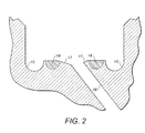
- the fillets 15 may be undercut, as shown in Figure 2 , and the orifices 16 may have a chamfer 17 at their mouths in the journal surfaces.
- Induction hardening is applied to a selected hardened area 18 of the surface of the component 10 with a zone around the orifice 16 which is left substantially unhardened, i.e. an "exclusion zone".
- the selected hardened area 18 is applied to the surface of the journal 11,13 in two or more bands, which avoid the orifice 16 and chamfer 17. This leaves the exclusion zone around the orifice 16, which is the mouth of the oil duct on the journal 11,13, which is substantially free from induction hardening.
- the exclusion zone also encompasses the radiussed fillets 15, although a component 10 may only have an exclusion zone around the orifice 16.
- the geometry of the orifice 16 and oil duct, and radiussed fillets 15 if included, may not go through the heating and rapid cooling cycle that contributes to crack generation around the orifice 16 or at the radiussed fillets 15.
- the total induction hardened area 18 should be as wide as possible, with the exclusion zone beginning just shy of the orifice 16, or chamfer 17 if present.
- the exclusion zone comprises an annular band around the orifice 16.
- the width of the surface of the journals 11,13 is 43.585 ⁇ 0.115mm.
- the depth and width of the hardened bands 18 applied on either side of the oil duct orifice 16 are 2mm and 8.3mm respectively and the bands 18 are applied 8.4 ⁇ 0.75mm from the webs 14.
- the exclusion zone is 0.5 ⁇ 0.25mm.
- the depth of the hardened area 18 may be similar to that produced in a traditional induction hardened component, for example to allow for surface regrinding of the journals 11,13.
- the band induction hardening pattern illustrated in Figure 2 is primarily designed for wear resistance. However it is known in the production of crankshafts to use fillet induction hardening for fatigue strength enhancement. This requires extending the induction hardened zone around each fillet 15. If this is desirable in the component 10, then the sole exclusion zone may be the area around the orifice 16.
- the induction hardening process required to produce the hardening patterns of the present disclosure may be carried out using known equipment currently in use. However it may be necessary to design the inductors, which include the induction coils, to create the required pattern according to the nature and design of the component.
- the induction hardening process generally comprises the steps of positioning the inductors close to the selected portions of the component, applying power to the coils to produce the localised heating by induction, followed by quenching.
- the power, times and temperatures to be used will be apparent to a person skilled in the art of conventional induction hardening.
- the invention has industrial applicability in the production of crankshafts and many other components which include orifices and ducts and are made of materials such as steel, ductile iron and other ferrous metals, which require hardening over a portion of a surface thereof to prevent distortion, in particular bend, twist and axial growth.
Landscapes
- Engineering & Computer Science (AREA)
- Chemical & Material Sciences (AREA)
- Mechanical Engineering (AREA)
- Physics & Mathematics (AREA)
- Thermal Sciences (AREA)
- Crystallography & Structural Chemistry (AREA)
- Materials Engineering (AREA)
- Metallurgy (AREA)
- Organic Chemistry (AREA)
- General Engineering & Computer Science (AREA)
- Ocean & Marine Engineering (AREA)
- Shafts, Cranks, Connecting Bars, And Related Bearings (AREA)
- Heat Treatment Of Articles (AREA)
Abstract
The invention relates to improvements in the selective hardening of components containing orifices and, in particular, to components such as crankshafts for internal combustion engines. An induction hardened component comprises a surface and an orifice in the surface and extending away from the surface. An area of the surface is induction hardened, which induction hardened area excludes a zone around the orifice.
Description
- The invention relates to improvements in the selective hardening of components containing an orifice.
- It is a known practice to improve the wear and fatigue characteristics of components, such as crankshafts, by induction hardening. Induction hardening is a form of heat treatment which uses an induction coil to produce localised heating. The heated component is quenched to induce a martensitic transformation to produce a hardened surface. Induction heating is a particularly convenient process to achieve this as it is a non-contact heating process which can target a specific area, or areas, of the component.
-
US-A-2002/0040619 describes some of the disadvantages of conventional induction hardening, such as component distortion and energy consumption. To overcome the disadvantages described this prior art document proposes the selective hardening of a crankshaft in just the oil hole breakout zones and the thrust face fillets. - When induction hardening crankshafts and the like which include oil ducts or other orifices, cracking is a major risk in particular where the oil hole drilling is not at a right angle to the shaft surface. This is because the masses of metal between the drilling and the shaft surface are largely unequal, leading to complex thermal expansion/contraction cycles.
- According to the present disclosure there is provided an induction hardened component comprising a surface and an orifice in the surface, wherein an area of the surface is induction hardened, which induction hardened area excludes a zone around the orifice which is substantially unhardened.
- The present disclosure also provides a method of induction hardening a component comprising a surface and an orifice in the surface, wherein an area of the surface is induction hardened, which induction hardened area is produced such that it excludes a zone around the orifice which is substantially unhardened.
- An embodiment of an induction hardened component according to the present disclosure is now described, by way of example, with reference to the accompanying drawings in which:-
-
Figure 1 is a side elevation of a part of a crankshaft for an internal combustion engine; and -
Figure 2 is a schematic diagram showing localised sites of induction hardening. -
Figure 1 illustrates one example of a component 10 having anorifice 16. The component 10 comprises a crankshaft for an internal combustion engine and includes oil ducts. Crankshafts are typically made from cast iron or steel and may generally comprisemain journals 11 aligned on thecrankshaft axis 12 which provide highly polished radially facing circumferential bearing surfaces on which the main bearings may be mounted. Located between themain journals 11, and offset from thecrankshaft axis 12, arerod journals 13, which may be highly polished surfaces to which the connecting rods can attach. - The main and
rod journals webs 14. Where the main androd journals webs 14 there is typically aradiussed fillet 15. Each adjacent pair of main journals androd journals orifice 16 in the surface of eachjournal journals fillets 15 may be undercut, as shown inFigure 2 , and theorifices 16 may have achamfer 17 at their mouths in the journal surfaces. - Induction hardening is applied to a selected hardened
area 18 of the surface of the component 10 with a zone around theorifice 16 which is left substantially unhardened, i.e. an "exclusion zone". In the example shown inFigure 2 the selected hardenedarea 18 is applied to the surface of thejournal orifice 16 and chamfer 17. This leaves the exclusion zone around theorifice 16, which is the mouth of the oil duct on thejournal radiussed fillets 15, although a component 10 may only have an exclusion zone around theorifice 16. This means that the geometry of theorifice 16 and oil duct, and radiussedfillets 15 if included, may not go through the heating and rapid cooling cycle that contributes to crack generation around theorifice 16 or at theradiussed fillets 15. Ideally the total induction hardenedarea 18 should be as wide as possible, with the exclusion zone beginning just shy of theorifice 16, or chamfer 17 if present. - In another embodiment the exclusion zone comprises an annular band around the
orifice 16. - In one example of a crankshaft made from SGI cast iron the width of the surface of the
journals bands 18 applied on either side of theoil duct orifice 16 are 2mm and 8.3mm respectively and thebands 18 are applied 8.4 ± 0.75mm from thewebs 14. The exclusion zone is 0.5 ± 0.25mm. These parameters may vary according to the nature, intended use and configuration of the component. - All other details of the induction hardening pattern may be as traditionally carried out. The depth of the hardened
area 18 may be similar to that produced in a traditional induction hardened component, for example to allow for surface regrinding of thejournals - The band induction hardening pattern illustrated in
Figure 2 is primarily designed for wear resistance. However it is known in the production of crankshafts to use fillet induction hardening for fatigue strength enhancement. This requires extending the induction hardened zone around eachfillet 15. If this is desirable in the component 10, then the sole exclusion zone may be the area around theorifice 16. - The induction hardening process required to produce the hardening patterns of the present disclosure may be carried out using known equipment currently in use. However it may be necessary to design the inductors, which include the induction coils, to create the required pattern according to the nature and design of the component.
- The induction hardening process generally comprises the steps of positioning the inductors close to the selected portions of the component, applying power to the coils to produce the localised heating by induction, followed by quenching. The power, times and temperatures to be used will be apparent to a person skilled in the art of conventional induction hardening.
- The invention has industrial applicability in the production of crankshafts and many other components which include orifices and ducts and are made of materials such as steel, ductile iron and other ferrous metals, which require hardening over a portion of a surface thereof to prevent distortion, in particular bend, twist and axial growth.
Claims (13)
- An induction hardened component (10) comprising a surface and an orifice (16) in the surface, wherein an area (18) of the surface is induction hardened, which induction hardened area (18) excludes a zone around the orifice (16) which is substantially unhardened.
- An induction hardened component (10) as claimed in claim 1 in which the induction hardened area (18) comprises induction hardened bands on either side of the orifice (16).
- An induction hardened component (10) as claimed in claim 1 in which the unhardened zone comprises an annular band around the orifice (16).
- An induction hardened component (10) as claimed in any one of the preceding claims further comprising at least one radiussed portion connecting said surface to another portion of the component, wherein the hardened area (18) excludes the radiussed portion.
- An induction hardened component (10) as claimed in any one of claims 1 t0 3 further comprising at least one radiussed portion connecting said surface to another portion of the component (10), wherein the hardened area (18) includes the radiussed portion.
- An induction hardened component (10) as claimed in any one of the preceding claims comprising a crankshaft, said crankshaft comprising:at least one main journal (11) having a radially facing circumferential surface;at least one rod journal (13) having a radially facing circumferential surface;a web portion (14) extending between adjacent main and rod journals (11,13);a circumferential fillet (15) joining the journals (11,13) to the web portion (14);at least one oil duct extending through the main and rod journals (11,13) and terminating at an orifice (16) in the surface of each journal (11,13);wherein the hardened area (18) comprises an area of the surface of each journal (11,13), which hardened area (18) excludes a zone around the orifice (16) in each surface which is substantially unhardened.
- An induction hardened component (10) as claimed in claim 6 when dependant on any one of claims 1 to 4 in which the hardened area (18) excludes the circumferential fillet.
- An induction hardened component (10) as claimed in claim 6 when dependant on any one of claims 1, 2, 3 and 5 in which the hardened area (18) includes at least a part of the circumferential fillet.
- A method of induction hardening a component (10) comprising a surface and an orifice (16) in the surface, wherein an area (18) of the surface is induction hardened, which induction hardened area (18) is formed such that it excludes a zone around the orifice (16) which is substantially unhardened.
- A method as claimed in claim 9 in which the induction hardened area (18) is formed as induction hardened bands on opposing sides of the orifice (16).
- A method as claimed in claim 9 in which the induction hardened area (18) is formed as an annular band around the orifice (16).
- A method as claimed in any one of claims 9 to 11 in which the component (10) further comprises at least one radiussed portion connecting one or both sides of said surface to another portion of the component (10), wherein the hardened area (18) is formed such that it excludes the radiussed portion.
- A method as claimed in any one of claims 9 to 11 in which the component (10) further comprises at least one radiussed portion connecting one or both sides of said surface to another portion of the component (10), wherein the hardened area (18) is formed in the radiussed portion.
Priority Applications (1)
| Application Number | Priority Date | Filing Date | Title |
|---|---|---|---|
| EP10194360A EP2463391A1 (en) | 2010-12-09 | 2010-12-09 | Induction hardened component containing a hole which is unhardened. |
Applications Claiming Priority (1)
| Application Number | Priority Date | Filing Date | Title |
|---|---|---|---|
| EP10194360A EP2463391A1 (en) | 2010-12-09 | 2010-12-09 | Induction hardened component containing a hole which is unhardened. |
Publications (1)
| Publication Number | Publication Date |
|---|---|
| EP2463391A1 true EP2463391A1 (en) | 2012-06-13 |
Family
ID=43901342
Family Applications (1)
| Application Number | Title | Priority Date | Filing Date |
|---|---|---|---|
| EP10194360A Withdrawn EP2463391A1 (en) | 2010-12-09 | 2010-12-09 | Induction hardened component containing a hole which is unhardened. |
Country Status (1)
| Country | Link |
|---|---|
| EP (1) | EP2463391A1 (en) |
Cited By (3)
| Publication number | Priority date | Publication date | Assignee | Title |
|---|---|---|---|---|
| CN103291732A (en) * | 2013-04-16 | 2013-09-11 | 中国兵器工业集团第七0研究 | Oilhole chamfer structure of engine crankshaft |
| CN107002897A (en) * | 2014-12-16 | 2017-08-01 | 罗伯特·博世有限公司 | Pressure limiting valve |
| US10161014B2 (en) | 2016-01-08 | 2018-12-25 | Ford Motor Company | Laser hardened crankshaft |
Citations (8)
| Publication number | Priority date | Publication date | Assignee | Title |
|---|---|---|---|---|
| US2213241A (en) * | 1934-03-29 | 1940-09-03 | Ohio Crankshaft Co | Method of producing a heat treated article |
| US2930603A (en) * | 1957-05-03 | 1960-03-29 | Don R Voss | Method and apparatus for heat treating articles with open end bores |
| US3701874A (en) * | 1967-08-30 | 1972-10-31 | Toyo Kogyo Co | Apparatus for induction hardening of anti-wear mechanical members |
| JP2001214217A (en) * | 2000-01-28 | 2001-08-07 | Fuji Electronics Industry Co Ltd | Induction hardening coil, induction hardening device and induction hardening method |
| US20020040619A1 (en) | 2000-10-06 | 2002-04-11 | Hatton Chris R. | Selectively hardened crankshaft and method for manufacturing the same |
| US20040113461A1 (en) * | 2001-11-27 | 2004-06-17 | Satoshi Shimizu | Press molding and its high frequency quenching method and its high frequency quenching system |
| JP2006207004A (en) * | 2005-01-31 | 2006-08-10 | Sumitomo Metal Ind Ltd | High frequency heating method |
| JP2008144230A (en) * | 2006-12-11 | 2008-06-26 | Dai Ichi High Frequency Co Ltd | Heat treatment method and apparatus for thin plate member |
-
2010
- 2010-12-09 EP EP10194360A patent/EP2463391A1/en not_active Withdrawn
Patent Citations (8)
| Publication number | Priority date | Publication date | Assignee | Title |
|---|---|---|---|---|
| US2213241A (en) * | 1934-03-29 | 1940-09-03 | Ohio Crankshaft Co | Method of producing a heat treated article |
| US2930603A (en) * | 1957-05-03 | 1960-03-29 | Don R Voss | Method and apparatus for heat treating articles with open end bores |
| US3701874A (en) * | 1967-08-30 | 1972-10-31 | Toyo Kogyo Co | Apparatus for induction hardening of anti-wear mechanical members |
| JP2001214217A (en) * | 2000-01-28 | 2001-08-07 | Fuji Electronics Industry Co Ltd | Induction hardening coil, induction hardening device and induction hardening method |
| US20020040619A1 (en) | 2000-10-06 | 2002-04-11 | Hatton Chris R. | Selectively hardened crankshaft and method for manufacturing the same |
| US20040113461A1 (en) * | 2001-11-27 | 2004-06-17 | Satoshi Shimizu | Press molding and its high frequency quenching method and its high frequency quenching system |
| JP2006207004A (en) * | 2005-01-31 | 2006-08-10 | Sumitomo Metal Ind Ltd | High frequency heating method |
| JP2008144230A (en) * | 2006-12-11 | 2008-06-26 | Dai Ichi High Frequency Co Ltd | Heat treatment method and apparatus for thin plate member |
Cited By (3)
| Publication number | Priority date | Publication date | Assignee | Title |
|---|---|---|---|---|
| CN103291732A (en) * | 2013-04-16 | 2013-09-11 | 中国兵器工业集团第七0研究 | Oilhole chamfer structure of engine crankshaft |
| CN107002897A (en) * | 2014-12-16 | 2017-08-01 | 罗伯特·博世有限公司 | Pressure limiting valve |
| US10161014B2 (en) | 2016-01-08 | 2018-12-25 | Ford Motor Company | Laser hardened crankshaft |
Similar Documents
| Publication | Publication Date | Title |
|---|---|---|
| CN103124841B (en) | Piston and the manufacture method of piston for internal combustion engine | |
| US20140260787A1 (en) | Selectively strengthened crankshaft | |
| US20020040619A1 (en) | Selectively hardened crankshaft and method for manufacturing the same | |
| EP2463391A1 (en) | Induction hardened component containing a hole which is unhardened. | |
| CN104831048A (en) | Heat treatment process for hull steel crankshaft | |
| CN104074622A (en) | Piston with integrated steel crown and iron skirt and production method thereof | |
| CN101755060B (en) | Functionally graded powder metal components | |
| US8221563B2 (en) | Method of making a diesel-engine crankshaft | |
| JP7462781B2 (en) | Crankshaft | |
| JP2011190489A (en) | Method for manufacturing crankshaft in internal combustion engine, and crankshaft | |
| US8691029B2 (en) | Reduced ferrite steel liner | |
| Doyon et al. | Induction hardening of crankshafts and camshafts | |
| CN208619512U (en) | The Steel Crankshafts of the medium-and-large-sized diesel engine of high pressure-charging | |
| CN102199702A (en) | Composite strengthening heat treatment technology of internal combustion engine crankshaft | |
| WO2013087650A1 (en) | Method for induction hardening of crankshafts made from spheroidal graphite cast iron and induction hardened crankshaft | |
| JP4254345B2 (en) | High strength connecting rod and manufacturing method thereof | |
| CN111334656B (en) | Method for heat treatment using a gradual temperature profile | |
| JP3858886B2 (en) | Crankshaft quenching method, quenching apparatus, and crankshaft manufacturing method | |
| CN108716508A (en) | The Steel Crankshafts and its treatment process of the medium-and-large-sized diesel engine of high pressure-charging | |
| RU2673900C1 (en) | Method of repairing strengthened by induction hardening crankshafts of internal combustion engines | |
| JP6740907B2 (en) | Induction hardened crankshaft | |
| JP7795121B2 (en) | Crankshaft and manufacturing method thereof | |
| Rudnev | The day after tomorrow–the future of induction heating | |
| Singh | Establishing core hardness by induction hardening process for crankshaft | |
| KR101305121B1 (en) | Fillet rolling-method of crank shaft for vehicle |
Legal Events
| Date | Code | Title | Description |
|---|---|---|---|
| PUAI | Public reference made under article 153(3) epc to a published international application that has entered the european phase |
Free format text: ORIGINAL CODE: 0009012 |
|
| AK | Designated contracting states |
Kind code of ref document: A1 Designated state(s): AL AT BE BG CH CY CZ DE DK EE ES FI FR GB GR HR HU IE IS IT LI LT LU LV MC MK MT NL NO PL PT RO RS SE SI SK SM TR |
|
| AX | Request for extension of the european patent |
Extension state: BA ME |
|
| STAA | Information on the status of an ep patent application or granted ep patent |
Free format text: STATUS: THE APPLICATION IS DEEMED TO BE WITHDRAWN |
|
| 18D | Application deemed to be withdrawn |
Effective date: 20121214 |