EP2463182A1 - Self-adaptive method for mounting side doors on motor-vehicle bodies - Google Patents
Self-adaptive method for mounting side doors on motor-vehicle bodies Download PDFInfo
- Publication number
- EP2463182A1 EP2463182A1 EP10194673A EP10194673A EP2463182A1 EP 2463182 A1 EP2463182 A1 EP 2463182A1 EP 10194673 A EP10194673 A EP 10194673A EP 10194673 A EP10194673 A EP 10194673A EP 2463182 A1 EP2463182 A1 EP 2463182A1
- Authority
- EP
- European Patent Office
- Prior art keywords
- hinge elements
- door
- mounting
- doors
- hinge
- Prior art date
- Legal status (The legal status is an assumption and is not a legal conclusion. Google has not performed a legal analysis and makes no representation as to the accuracy of the status listed.)
- Granted
Links
Images

Classifications
-
- B—PERFORMING OPERATIONS; TRANSPORTING
- B62—LAND VEHICLES FOR TRAVELLING OTHERWISE THAN ON RAILS
- B62D—MOTOR VEHICLES; TRAILERS
- B62D65/00—Designing, manufacturing, e.g. assembling, facilitating disassembly, or structurally modifying motor vehicles or trailers, not otherwise provided for
- B62D65/02—Joining sub-units or components to, or positioning sub-units or components with respect to, body shell or other sub-units or components
- B62D65/06—Joining sub-units or components to, or positioning sub-units or components with respect to, body shell or other sub-units or components the sub-units or components being doors, windows, openable roofs, lids, bonnets, or weather strips or seals therefor
-
- B—PERFORMING OPERATIONS; TRANSPORTING
- B62—LAND VEHICLES FOR TRAVELLING OTHERWISE THAN ON RAILS
- B62D—MOTOR VEHICLES; TRAILERS
- B62D65/00—Designing, manufacturing, e.g. assembling, facilitating disassembly, or structurally modifying motor vehicles or trailers, not otherwise provided for
- B62D65/02—Joining sub-units or components to, or positioning sub-units or components with respect to, body shell or other sub-units or components
- B62D65/024—Positioning of sub-units or components with respect to body shell or other sub-units or components
- B62D65/028—Positioning of sub-units or components with respect to body shell or other sub-units or components by determining relative positions by measurement
-
- Y—GENERAL TAGGING OF NEW TECHNOLOGICAL DEVELOPMENTS; GENERAL TAGGING OF CROSS-SECTIONAL TECHNOLOGIES SPANNING OVER SEVERAL SECTIONS OF THE IPC; TECHNICAL SUBJECTS COVERED BY FORMER USPC CROSS-REFERENCE ART COLLECTIONS [XRACs] AND DIGESTS
- Y10—TECHNICAL SUBJECTS COVERED BY FORMER USPC
- Y10T—TECHNICAL SUBJECTS COVERED BY FORMER US CLASSIFICATION
- Y10T29/00—Metal working
- Y10T29/49—Method of mechanical manufacture
- Y10T29/49764—Method of mechanical manufacture with testing or indicating
- Y10T29/49769—Using optical instrument [excludes mere human eyeballing]
-
- Y—GENERAL TAGGING OF NEW TECHNOLOGICAL DEVELOPMENTS; GENERAL TAGGING OF CROSS-SECTIONAL TECHNOLOGIES SPANNING OVER SEVERAL SECTIONS OF THE IPC; TECHNICAL SUBJECTS COVERED BY FORMER USPC CROSS-REFERENCE ART COLLECTIONS [XRACs] AND DIGESTS
- Y10—TECHNICAL SUBJECTS COVERED BY FORMER USPC
- Y10T—TECHNICAL SUBJECTS COVERED BY FORMER US CLASSIFICATION
- Y10T29/00—Metal working
- Y10T29/49—Method of mechanical manufacture
- Y10T29/49764—Method of mechanical manufacture with testing or indicating
- Y10T29/49778—Method of mechanical manufacture with testing or indicating with aligning, guiding, or instruction
-
- Y—GENERAL TAGGING OF NEW TECHNOLOGICAL DEVELOPMENTS; GENERAL TAGGING OF CROSS-SECTIONAL TECHNOLOGIES SPANNING OVER SEVERAL SECTIONS OF THE IPC; TECHNICAL SUBJECTS COVERED BY FORMER USPC CROSS-REFERENCE ART COLLECTIONS [XRACs] AND DIGESTS
- Y10—TECHNICAL SUBJECTS COVERED BY FORMER USPC
- Y10T—TECHNICAL SUBJECTS COVERED BY FORMER US CLASSIFICATION
- Y10T29/00—Metal working
- Y10T29/49—Method of mechanical manufacture
- Y10T29/49764—Method of mechanical manufacture with testing or indicating
- Y10T29/49778—Method of mechanical manufacture with testing or indicating with aligning, guiding, or instruction
- Y10T29/4978—Assisting assembly or disassembly
Definitions
- the present invention refers to the field of methods for manufacturing motor-vehicle bodies and in particular to the methods for assembling side doors, of the hinged type, on motor-vehicle bodies.
- the invention has the following main objects:
- the invention provides a method having the characteristics indicated in the attached claim 1.
- a geometric on-line detection is carried out of the points qualifying the coupling of the side doors with their respective receiving portions on each body side, assuming the plane on which the hinge elements connected to the car body are positioned as a reference plane (the coordinates X,Y,Z respectively corresponding to the longitudinal dimension, the transverse dimension and the vertical dimension of the body).
- mounting dimensions are determined in "real time” which are required in the self-adaptive assembling of the hinge elements on the body, for compensating the deviations ⁇ with respect to the project dimensions - induced by the sheet-metal pressing processes and the assembling operations of the parts constituting the car body, thus ensuring that the positioning of the doors is consistent with the project drawing of the "body complete with movable parts” assembly.
- a specifically developed software program which transforms the geometric detections into numerical data which can be fed to the machine controls for performing the self-adaptive operations described hereinafter.
- the software program depends from the body shape and takes into account also the elastic yielding of the vehicle structure due to the weight of the mounted doors and the nominal pressures required for ensuring the fluid sealing of the applied elastomeric wheather-strips.
- the dimensions of the hinge elements connected to the car body and their positioning on the body sides constitute the variables of the self-adaptive process, through which it is possible to provide a compensation of the deviations induced by the chain of tolerances which are inherent in systems for car body manufacturing, this compensation being obtained "on-process", i.e.
- the doors completed with door hinge elements are produced with project nominal dimensions with sufficiently reduced tolerances, by using a method for mounting the hinge elements which is capable of compensating the deviations from the tolerance range induced by the process for forming the door frames, this compensation being made "una tantum” (only once) when setting up the manufacturing process, or "periodically” according to the production batches.
- a geometric detection is carried-out on-line of the points qualifying the coupling of the side doors with the door receiving portions of the body sides.
- Figure 1 of the attached drawings is a side view of a motor-vehicle body in which the points of the body which are subjected to this detection operation are shown, with reference to a non-limiting example provided herein merely for illustration purposes.
- coordinates X,Y,Z are associated, according to a standard practice, to the longitudinal direction, the transverse direction and the vertical direction respectively of the vehicle body.
- the respective measured dimensions are indicated.
- figure 1 indicates both points detected as primary references for measurements (see rhombi having black vertices), and points detected as secondary references for measurements (see rhombi with white vertices) as well as points (see symbols surrounded by rectangles) detected for determining the mounting (or manufacturing) dimensions in the self-adaptive mounting of the hinge elements on the vehicle body.
- a programmable optoelectronic measurement system is provided on-line, comprising:
- the mounting dimensions are defined which are required for mounting the side doors consistently with the project drawing of the side view and the cross-section of the assembly constituted by the vehicle body completed with movable parts.
- the processing electronic unit makes use of a software program, which transforms the geometric detections into numerical data which can be fed to the unit controlling the robots which perform the self-adaptive operations described hereinafter.
- This software depends on the shape of the vehicle body and considers a geometric correction required to compensate the effect of the elastic yielding of the vehicle structure due to the weight of the completed doors mounted on the vehicle bodies and the nominal pressures on the elastomeric weather-strips, required for ensuring the sealing feature of the doors in their closed condition.
- the mode and frequency of the specific detections for each produced model are controlled by the software program, which also applies determined interpolation rules to the measured Y dimensions.
- the mounting dimensions resulting from this elaboration process enable a compensation - when mounting the body hinge elements on the body and the door hinge elements on the door ⁇ of the deviations with respect to the design nominal dimensions which are induced by the chain of manufacturing tolerances resulting from the parts of pressed sheet-metal and/or by the systems for assembling and welding vehicle bodies and door frames.
- the mounting methods described hereinafter guarantee a sufficient degree of accuracy, both with respect to aesthetic quality (proper correspondence between door profiles and associated coupling gaps) and with respect to functional quality (easy opening and closing of the doors, proper sealing by the weather-strips).
- the processing electronic unit determines the "mounting dimensions", for the self-adaptive mounting of the hinge elements on the two body sides.
- the hinge elements are secured onto coplanar sections of the body side surfaces, whose plane X/Z is assumed as a reference plane for measuring the Y dimensions orthogonal thereto.
- the abovementioned operation for detecting and determining the mounting dimensions is carried-out on-line and according to the pace of the bodies assembly process.
- control electronic unit which receives and processes the measurement data is connected to the electronic control of means for automated machining and mounting of the body hinge elements to the vehicle body. At least one multi-axis manipulator robot is used for this automated mounting.
- an optical marking is provided of required references on the body sides for the correct positioning of the hinge elements along X and Z, as schematically illustrated in figure 2 ; such marking is intended to be performed by the same robot that carries the measurement camera and which is also provided with a laser emitter device, with low power and accurate focusing.
- the method according to the invention provides two alternative methods for the self-adaptive mounting of the body hinge elements to the vehicle body.
- the rotary table supplies the following operating steps in sequence:
- an anthropomorphic robot having a vision system adapted for calibrating - at each cycle - the geometric references, according to two possible alternative solutions:
- the body hinge elements are mounted on the body manually.
- the hinge elements are arranged in a manner identical to that described above in the case of automatic mounting but the gripper tools are carried by a balanced supporting hoist instead of being carried by a robot, thus enabling the operator to pick up the pair of hinge elements on the body through manual control actuations, while guaranteeing maintaining the mutual geometric set-up of the two hinge elements during assembling.
- the operator positions the two hinge elements on the body placing them in contact with the flat coupling surfaces, by using said gripper tools. At this point, the operator adapts the position of the hinge elements on the plane X/Z, with the aid of the laser markings obtained as described previously.
- This manual adaptation is carried out with the help of a vision system, constituted by a camera provided with a screen and opto-acoustic sensors, the gripper tools being provided with a calibrated edge for the optical collimation.
- Doors constituted by frames of pressed steel sheet
- the correct positioning of the door hinge elements along Y and Z on the flat coupling surfaces is determined by the robot movement program, after a highly accurate calibration of the references with respect to the fixed tools at the work station.
- the deviation of the project nominal dimensions, in terms of the X position of the abovementioned coupling surfaces, which is induced by the sheet-metal pressing process and the assembling operations of the door frame, can be compensated either "una tantum" (only once) or periodically, depending on the batches of doors being produced, by suitably controlling the geometric detection system of the bodies through the previously described software program.
- the repeatability of the process and the accuracy required for positioning the hinge elements on the door along Y and Z is guaranteed by the periodic calibration of the intrinsic references of the station, which can be adapted to many product designs (with suitably reduced set-up times for station retooling).
- the periodic geometric control on the door modules determines the corrections to be introduced via software.
- the hinge elements on the door can be integrated in the casting.
- the required accuracy is obtained by means of machining - on a machine-center ⁇ of the door hinge elements and the flat surface sections on which the guides for the movable window panes are located.
- the machining of the seats receiving the bushings defining the hinge axis is carried out starting from references which correspond to the shape of the peripheral portions of the door receiving aperture on the vehicle body and guarantees satisfactory consistency with the project drawing in respect of proper conjugation of the doors with the door apertures on the vehicle body. Therefore, the operation described previously with reference to the steel sheet doors is not required with this embodiment.
- the doors can be mounted on the vehicle body in a simple and quick manner, since there is no need of manual or semiautomatic adaptations along the lines for completing the bodies, as it occurs in the conventional art, in orderto the bi-univocally couple each door to a a specific vehicle body,.
- the methods of the invention eliminate critical operations and simplify the logistic system required for the management of the production processes.
- the same painting systems can be used, painting the doors in parallel with the bodies, and arranging them on side supports applied on the transfer tools used in the various stages of the painting process, after cyclic application and removal of snap caps required to protect the hinge seats for the hinge pin.
Landscapes
- Engineering & Computer Science (AREA)
- Manufacturing & Machinery (AREA)
- Chemical & Material Sciences (AREA)
- Combustion & Propulsion (AREA)
- Transportation (AREA)
- Mechanical Engineering (AREA)
- Automobile Manufacture Line, Endless Track Vehicle, Trailer (AREA)
Abstract
- detecting, by means of an optoelectronic system, a plurality of dimensions measured along coordinates X,Y,Z on the vehicle body, with the aid of proper references, for qualifying the geometric conditions of the coupling between the doors and the door-receiving portions,
- determining, on the basis of the detected dimensions, the mounting positions of each body hinge element to be secured to the vehicle body, so as to obtain that the pivots for support and articulation of the doors are consistent with the respective door-receiving portions on the vehicle body side, according to an assembly project drawing,
- mounting the abovementioned body hinge elements on the body in the positions thus determined,
- providing the doors with their respective door hinge elements, while adapting via software a system for mounting the door hinge elements in order to substantially ensure consistency with a project assembly drawing,
- mounting the doors on the vehicle body by connecting the body hinge elements and the door hinge elements to each other by simply inserting the respective articulation pins.
Description
- The present invention refers to the field of methods for manufacturing motor-vehicle bodies and in particular to the methods for assembling side doors, of the hinged type, on motor-vehicle bodies.
- The invention has the following main objects:
- improving functional and aesthetic quality of the produced bodies,
- eliminating manual operations critical for reliability of the finished product, which are currently applied in the known methods,
- simplifying factory logistic systems,
- shortening the time required for setting up production of new motor-vehicle models.
- With the aim of attaining such objects, the invention provides a method having the characteristics indicated in the attached claim 1.
- Further advantageous characteristics of the invention are specified in the dependent claims.
- According to the invention, in a system for assembling motor-vehicle bodies, for all the produced bodies, or only for some determined bodies each representing a corresponding batch of produced bodies, a geometric on-line detection is carried out of the points qualifying the coupling of the side doors with their respective receiving portions on each body side, assuming the plane on which the hinge elements connected to the car body are positioned as a reference plane (the coordinates X,Y,Z respectively corresponding to the longitudinal dimension, the transverse dimension and the vertical dimension of the body). With the aid of an optoelectronic system, mounting dimensions are determined in "real time" which are required in the self-adaptive assembling of the hinge elements on the body, for compensating the deviations ― with respect to the project dimensions - induced by the sheet-metal pressing processes and the assembling operations of the parts constituting the car body, thus ensuring that the positioning of the doors is consistent with the project drawing of the "body complete with movable parts" assembly.
- For this purpose a specifically developed software program is used, which transforms the geometric detections into numerical data which can be fed to the machine controls for performing the self-adaptive operations described hereinafter. The software program depends from the body shape and takes into account also the elastic yielding of the vehicle structure due to the weight of the mounted doors and the nominal pressures required for ensuring the fluid sealing of the applied elastomeric wheather-strips. The dimensions of the hinge elements connected to the car body and their positioning on the body sides constitute the variables of the self-adaptive process, through which it is possible to provide a compensation of the deviations induced by the chain of tolerances which are inherent in systems for car body manufacturing, this compensation being obtained "on-process", i.e. for each car body (for deviations which are not sufficiently stable from one body to the other), or "una tantum" (only once) when setting up the manufacturing process, or "periodically", for each batch of produced bodies (for deviations which are sufficiently stable for all bodies of a single batch).
- The doors completed with door hinge elements are produced with project nominal dimensions with sufficiently reduced tolerances, by using a method for mounting the hinge elements which is capable of compensating the deviations from the tolerance range induced by the process for forming the door frames, this compensation being made "una tantum" (only once) when setting up the manufacturing process, or "periodically" according to the production batches.
- By the above mentioned methods of the invention, specific doors are rendered biunivocally adapted to a specific body, so that mounting of the doors on the bodies and on the vehicles can be carried out with no need of performing manual or semiautomatic adaptations along the line for completing the body, which would require using suitable calibration instruments on each door and on each door receiving body portion.
- Further advantageous characteristics of the method of the present invention shall be described hereinafter, with references to the attached exemplifying drawings, in which:
-
figure 1 is a side view of a motor-vehicle body, in which points are indicated which are subjected to an optoelectronic detection, according to one embodiment of the method according to the invention, -
figure 2 shows a view of the detail 11 offigure 1 at an enlarged scale, where laser markings obtained in a further embodiment of the method according to the invention are indicated, and -
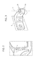
figure 3 shows a perspective view of a hinge element to be connected to the body. - According to the invention, within a system for assembling vehicle bodies, for all the produced bodies, or only for specific bodies each representing a corresponding batch of vehicle bodies, a geometric detection is carried-out on-line of the points qualifying the coupling of the side doors with the door receiving portions of the body sides.
-
Figure 1 of the attached drawings is a side view of a motor-vehicle body in which the points of the body which are subjected to this detection operation are shown, with reference to a non-limiting example provided herein merely for illustration purposes. In the present description, coordinates X,Y,Z are associated, according to a standard practice, to the longitudinal direction, the transverse direction and the vertical direction respectively of the vehicle body. Infigure 1 , for each point subjected to detection, the respective measured dimensions are indicated. Furthermore,figure 1 indicates both points detected as primary references for measurements (see rhombi having black vertices), and points detected as secondary references for measurements (see rhombi with white vertices) as well as points (see symbols surrounded by rectangles) detected for determining the mounting (or manufacturing) dimensions in the self-adaptive mounting of the hinge elements on the vehicle body. - With the aim of performing the abovementioned detection operation, according to the method of the invention a programmable optoelectronic measurement system is provided on-line, comprising:
- a multi-axis robot, with accurate repeatable positioning capability,
- a camera, provided with an accurate telemetric sensor, applied to the wrist of the robot,
- an electronic unit connected to the camera, which processes the measurement data in real time according to a predetermined software program;
- a support for positioning the vehicle body on reference elements which mostly are adapted to engage the underbody, so as to locate it in a sufficiently accurate and repeatable manner with respect to a fixed reference at the work station where the abovementioned detection operation is carried out; such support can be positioned on a rotary table having a vertical axis, to enable a bilateral detection by using a single optoelectronic system.
- Starting from the measurements carried-out in the abovementioned detection station, the mounting dimensions are defined which are required for mounting the side doors consistently with the project drawing of the side view and the cross-section of the assembly constituted by the vehicle body completed with movable parts.
- When starting the pre-series production of a new model, systematic detection of the dimensions of interest is accomplished, so as to define proper frequency of measuring operations statistically.
- In order to reach the result of the doors being mounted consistently with the design nominal dimensions, the processing electronic unit makes use of a software program, which transforms the geometric detections into numerical data which can be fed to the unit controlling the robots which perform the self-adaptive operations described hereinafter.
- This software depends on the shape of the vehicle body and considers a geometric correction required to compensate the effect of the elastic yielding of the vehicle structure due to the weight of the completed doors mounted on the vehicle bodies and the nominal pressures on the elastomeric weather-strips, required for ensuring the sealing feature of the doors in their closed condition.
- The mode and frequency of the specific detections for each produced model are controlled by the software program, which also applies determined interpolation rules to the measured Y dimensions.
- The mounting dimensions resulting from this elaboration process enable a compensation - when mounting the body hinge elements on the body and the door hinge elements on the door ― of the deviations with respect to the design nominal dimensions which are induced by the chain of manufacturing tolerances resulting from the parts of pressed sheet-metal and/or by the systems for assembling and welding vehicle bodies and door frames.
- The mounting methods described hereinafter guarantee a sufficient degree of accuracy, both with respect to aesthetic quality (proper correspondence between door profiles and associated coupling gaps) and with respect to functional quality (easy opening and closing of the doors, proper sealing by the weather-strips).
- The adaptations which will be illustrated more in detail hereinafter can be performed either "on process", or through "una tantum" (only once) operations during the set-up stage of the product-process, or periodically, in relation to the analysis of measurements carried-out on each vehicle body or on each batch of bodies consecutively produced.
- According to the invention, once the dimensions are detected with regard to a plurality of points of the vehicle body qualifying the coupling of the doors with the body, the processing electronic unit determines the "mounting dimensions", for the self-adaptive mounting of the hinge elements on the two body sides.
- In the case of the embodiment considered herein and illustrated in
figure 1 , the hinge elements are secured onto coplanar sections of the body side surfaces, whose plane X/Z is assumed as a reference plane for measuring the Y dimensions orthogonal thereto. - The abovementioned operation for detecting and determining the mounting dimensions is carried-out on-line and according to the pace of the bodies assembly process.
- The abovementioned control electronic unit which receives and processes the measurement data is connected to the electronic control of means for automated machining and mounting of the body hinge elements to the vehicle body. At least one multi-axis manipulator robot is used for this automated mounting.
- If manual mounting is preferred, an optical marking is provided of required references on the body sides for the correct positioning of the hinge elements along X and Z, as schematically illustrated in
figure 2 ; such marking is intended to be performed by the same robot that carries the measurement camera and which is also provided with a laser emitter device, with low power and accurate focusing. - As visible in
figure 2 , in the case of the illustrated example there are provided: - a horizontal line "o", relevant for positioning along the vertical direction,
- two vertical lines "v", relevant for accurate positioning of the hinge rotational axis.
- Accurate visibility of the laser lines is obtained through two possible alternative solutions:
- slight incision of the sheet covering by means of thermal laser,
- laser marking on a photosensitive film, which is applied for this purpose at a required small area and removed, during pre-painting treatment of the vehicle body.
- As previously indicated, the method according to the invention provides two alternative methods for the self-adaptive mounting of the body hinge elements to the vehicle body.
- The following operating steps are provided:
- each pair of body hinge elements to be connected to the vehicle body (the configuration of one body hinge element is indicatively represented in the drawing of
figure 3 ) is arranged at a work station, this work station comprising:- ● the required gripper tools (two tools in the case of four-door models) for positioning, locking, gripping and transferring the two hinge elements, these tools being conceived so as to guarantee the correct orientation and coplanarity of the walls α, the alignment of the axes "a", and the correct distance between the sections β1.
- The attached
figure 3 illustrates an exemplifying drawing of a hinge element connected to the body and indicates the references used for preparing the self-adaptive mounting. The symbols in such figure have the following meaning:- α: plane of the hinge element to be secured to the vehicle body side;
- a: rotational axis of the door;
- β1: plane supporting the hinge element secured to the door;
- β2: plane or cone for abutment of the hinge pin;
- The upper and lower body hinge elements are coupled and positioned on the gripper tool in the following way:
- 1) insertion of the hinge elements along axis (a) on coaxial pins and on accurately spaced apart support planes β1,
- 2) orientation of the α walls by cooperation with a reference available at the work station,
- 3) gripping of the hinge elements through electro-actuated activation along axis (a), abutment at β2 and locking reaction between β1 and β2.
- The attached
- ● a rotary table moves a base supporting the abovementioned tools and the associated electro-controls for locking;
- ● a numerical control single-spindle milling unit, adapted to adjust the position of the mounting plane "on-process" according to the Y mounting dimensions transmitted by the previously described detection system.
- ● the required gripper tools (two tools in the case of four-door models) for positioning, locking, gripping and transferring the two hinge elements, these tools being conceived so as to guarantee the correct orientation and coplanarity of the walls α, the alignment of the axes "a", and the correct distance between the sections β1.
- The rotary table supplies the following operating steps in sequence:
- a) loading and locking of the two pairs of body hinge elements on the abovementioned gripper tools (one dedicated to the front door receiving body portions and the other to the rear door receiving body portions);
- b) parallel machining of the α walls of the two body hinge elements, which are manufactured with a machining allowance (overdimensioned thickness) adapted for the range of compensation required for the Y dimensions; this operating step is not required if the detection system ascertains a sufficient degree of repeatability for the Y measured dimensions. In this latter case, the required adaptation is carried out either "una tantum" (only once) or periodically for each production batch, adapting via software the system, described hereinafter, for mounting the door hinge elements which are connected to the doors;
- c) picking up the specific gripper tool for each door receiving body portion by means of the mounting robot.
- For the self-adaptive mounting, an anthropomorphic robot is provided having a vision system adapted for calibrating - at each cycle - the geometric references, according to two possible alternative solutions:
- detecting starting points identical to those assumed by the previously described detection system, regarding the dimensions along X and Z;
- detecting the previously mentioned laser markings.
- The following operating steps are provided for in succession:
- the robot transfers the pair of hinge elements by means of a gripper tool, and moves them close to the receiving flat surfaces of the vehicle body, adapting on process the positions of the elements on the plane X/Z, either on the basis of the mounting dimensions obtained from the previously described detection system, or according to direct detection by the vision system of the laser markings provided on the body (should this latter solution be used);
- the robot imparts a determined pressure along Y, through a unidirectional elastic cell, so as to bring the hinge elements against the coupling plane, guaranteeing the required stability of the hinge elements while they are being connected to the structure of the vehicle body side;
- after positioning, a second robot provided for the automatic fastening operation, inserts and fastens bolts for securing the hinge elements to the body, operating in a coordinated manner within the same station; fastening is carried out while the mounting robot keeps the pair of hinge elements stable against the coupling surfaces of the body;
- the mounting robot disengages the gripper tool and returns it to the cycle start position.
- The abovementioned mounting steps are intended to be carried out in parallel with the steps for preparing the subsequent hinge elements to be connected to a respective body.
- The body hinge elements are mounted on the body manually. The hinge elements are arranged in a manner identical to that described above in the case of automatic mounting but the gripper tools are carried by a balanced supporting hoist instead of being carried by a robot, thus enabling the operator to pick up the pair of hinge elements on the body through manual control actuations, while guaranteeing maintaining the mutual geometric set-up of the two hinge elements during assembling. The operator positions the two hinge elements on the body placing them in contact with the flat coupling surfaces, by using said gripper tools. At this point, the operator adapts the position of the hinge elements on the plane X/Z, with the aid of the laser markings obtained as described previously. This manual adaptation is carried out with the help of a vision system, constituted by a camera provided with a screen and opto-acoustic sensors, the gripper tools being provided with a calibrated edge for the optical collimation.
- The operator then actuates the stop of the gripper tool against the coupling surface on the body and introduces and fastens the connecting bolts.
- Lastly, the operator controls the disengagement of the gripper and returns the gripper tool to the cycle start position.
- After ascertaining the positioning consistency of the doors on the bodies, through the automatic or servo-assisted adaptation of the connection elements, the same must be made with the cooperating hinge elements to be applied on the doors.
- The methods provided for this operation are different depending upon the construction characteristics of the doors.
- For this type of construction the following steps are provided:
- the complete door structures, with inner frame and outer panel, are positioned and locked on specific tools, ensuring that the locating references at the mounting station are consistent with the shape of the peripheral contour of the door receiving apertures on the body sides, according to the project assembly drawing;
- the pair of hinge elements on the door is arranged on a specific gripper tool, which guarantees correct mutual positioning thereof (coaxiality of the bushings serving as seats for the hinge pin, proper distance between the support planes on the body hinge elements, proper orientation of the contact planes with the structure of the door); the criteria for arranging and gripping the hinge elements are similar to those described previously with reference to the body hinge elements;
- an anthropomorphic robot, installed also for automatic fastening, picks up the gripper tool, on which the door hinge elements are arranged, receives the two bolts required for the connection, moves the door hinge elements close to the coupling surfaces on the door frame, and inserts the two connecting bolts;
- before tightening the bolts, the robot adapts the position of the hinge elements according to the set movement program and imparts a determined pressure perpendicularly to the coupling surface, to an extent controlled by means of a unidirectional elastic cell;
- the robot actuates the controlled simultaneous tightening of the two hinge elements on the door;
- the robot releases the "gripper tool" and returns it to the cycle start area. The described robotized system is capable of installing an entire set of doors, provided it is equipped with the required specific tools.
- The correct positioning of the door hinge elements along Y and Z on the flat coupling surfaces is determined by the robot movement program, after a highly accurate calibration of the references with respect to the fixed tools at the work station.
- The deviation of the project nominal dimensions, in terms of the X position of the abovementioned coupling surfaces, which is induced by the sheet-metal pressing process and the assembling operations of the door frame, can be compensated either "una tantum" (only once) or periodically, depending on the batches of doors being produced, by suitably controlling the geometric detection system of the bodies through the previously described software program.
- The repeatability of the process and the accuracy required for positioning the hinge elements on the door along Y and Z is guaranteed by the periodic calibration of the intrinsic references of the station, which can be adapted to many product designs (with suitably reduced set-up times for station retooling).
- The periodic geometric control on the door modules (carried out on each production batch) determines the corrections to be introduced via software.
- For this type of construction, the hinge elements on the door can be integrated in the casting. The required accuracy is obtained by means of machining - on a machine-center ― of the door hinge elements and the flat surface sections on which the guides for the movable window panes are located.
- The machining of the seats receiving the bushings defining the hinge axis is carried out starting from references which correspond to the shape of the peripheral portions of the door receiving aperture on the vehicle body and guarantees satisfactory consistency with the project drawing in respect of proper conjugation of the doors with the door apertures on the vehicle body. Therefore, the operation described previously with reference to the steel sheet doors is not required with this embodiment.
- By the previously described methods the doors can be mounted on the vehicle body in a simple and quick manner, since there is no need of manual or semiautomatic adaptations along the lines for completing the bodies, as it occurs in the conventional art, in orderto the bi-univocally couple each door to a a specific vehicle body,.
- Hence, there no longer arises the need for mounting the doors on the body before the painting process and subsequently removing them for final assembling operations, as it generally occurs in current conventional methods.
- Thus, the methods of the invention eliminate critical operations and simplify the logistic system required for the management of the production processes.
- In any case the same painting systems can be used, painting the doors in parallel with the bodies, and arranging them on side supports applied on the transfer tools used in the various stages of the painting process, after cyclic application and removal of snap caps required to protect the hinge seats for the hinge pin.
- Such arrangement of the doors spaced apart from, and parallel to the body enables a complete automation of the paint application process.
- Naturally, without prejudice to the principle of the method subject of the invention, the construction details and the embodiments may vary with respect to what has been described and illustrated purely by way of example, without departing from the scope of the present invention.
Claims (11)
- Method for mounting side doors on a motor-vehicle body, wherein the doors are connected to the body by means of a pair of hinges each providing a pivot for support and articulation of the door, each hinge comprising a first hinge element secured to the body, a second hinge element secured to the door, as well as a pin for their mutual rotational articulation,
said method being characterised in that it comprises the steps of:- detecting, by means of an optoelectronic system, a plurality of dimensions measured along coordinates X,Y,Z on the vehicle body, with the aid of proper references, for qualifying the geometric conditions of the coupling between the doors and the door-receiving portions,- determining, on the basis of the detected dimensions, the mounting positions of each body hinge element to be secured to the vehicle body, so as to obtain that the pivots for support and articulation of the doors are consistent with the respective door-receiving portions on the vehicle body side, according to an assembly project drawing,- mounting the abovementioned hinge elements on the body in the positions thus determined,- providing the doors with their respective door hinge elements, while adapting via software a system for mounting the door hinge elements in order to substantially ensure consistency with the project assembly drawing,- mounting the doors on the vehicle body by connecting the body hinge elements and the door hinge elements to each other by simply inserting the respective articulation pins, with no need for further adaptation and adjustment operations along the lines for completing the vehicle bodies and/or for the final assembly of the vehicle. - Method according to claim 1, characterised in that the abovementioned operation for detecting and determining the mounting dimensions is carried out on-line according to the pace of the body assembly line, so as to perform the required adaptations "on process".
- Method according to claim 2, characterised in that the operation for detecting the dimensions and determining the mounting positions is carried out by means of a programmable controlling system, which enables operating on several models, without requiring a set-up time.
- Method according to claim 3, characterised in that said controlling system is directly connected to systems for controlling automated machining and assembly means.
- Method according to claim 3, characterised in that said controlling system is also capable of controlling the optical marking - on the vehicle body - of the required references for the assisted manual mounting of the body hinge elements to be connected to the body.
- Method according to claim 1, characterised in that the abovementioned detection operation is carried out by:- first detecting at least three points of the flat surfaces of the body sides on which the body hinge elements are fastened,- assuming said surfaces as reference planes for the measurements along the Y direction,- carrying out the required interpolations of the measurement data, as a function of the optimisation of the coupling profiles between the doors and the respective door-receiving portions on the body sides.
- Method according to claim 1, characterised in that the abovementioned detection system is programmed to perform said step for determining the mounting dimensions, considering the coupling profiles defined by the shape of the vehicle body, as well as the elastic yielding of the vehicle structure due to the weight of the door and the pressure required for ensuring proper sealing action of the elastomeric weather-strips applied on the body.
- Method according to claim 5, characterised in that the references for mounting the body hinge elements on the body are obtained either through a slight incision by means of thermal laser, or alternatively through of laser marking on a photosensitive film, applied on a selected part of the body.
- Method according to claim 4, characterised in that each pair of hinge elements on the body is arranged at a work station so as to obtain:- proper orientation and coplanarity of the walls (α) of said body hinge elements which come into contact with the coupling surfaces on the body,- alignment and coincidence of the hinge axes (a) defined by the two body hinge elements,- proper mutual distance of support portions (β1) of the hinge elements along said hinge axis (a);- said method further being characterised in that the coplanar machining of the walls (α), is carried out by removing a machining allowance provided for obtaining the proper positioning of the hinge axis on the body along Y, and- in that the two body hinge elements thus machined are picked up by means of a gripper tool by a manipulator robot, which carries out the operation for self-adapting the two hinge elements on to the vehicle body.
- Method according to claim 9, characterised in that said manipulator robot positions the hinge elements on the body side, holding them stably by pushing them against their connection surfaces, with a controlled unidirectional pressure, while a second robot or another fastening system inserts and fastens the bolts which connect the hinge elements to the structure of the body.
- Method according to claim 1, characterised in that the hinge elements on the door are integrated in the structure of the door and are machined on a machine-center, consistently with flat surface portions on which guides for movable window panes are arranged.
Priority Applications (6)
| Application Number | Priority Date | Filing Date | Title |
|---|---|---|---|
| EP10194673A EP2463182B1 (en) | 2010-12-13 | 2010-12-13 | Self-adaptive method for mounting side doors on motor-vehicle bodies |
| US13/993,950 US9422016B2 (en) | 2010-12-13 | 2011-10-18 | Self-adaptive method for mounting side doors on motor-vehicle bodies |
| PCT/IB2011/054623 WO2012080855A1 (en) | 2010-12-13 | 2011-10-18 | Self-adaptive method for mounting side doors on motor-vehicle bodies |
| EP11799303.0A EP2651752B1 (en) | 2010-12-13 | 2011-10-18 | Self-adaptive method for mounting side doors on motor-vehicle bodies |
| ES11799303.0T ES2535952T3 (en) | 2010-12-13 | 2011-10-18 | Self-adaptive procedure for the assembly of side doors in auto vehicle bodies |
| PL11799303T PL2651752T3 (en) | 2010-12-13 | 2011-10-18 | Self-adaptive method for mounting side doors on motor-vehicle bodies |
Applications Claiming Priority (1)
| Application Number | Priority Date | Filing Date | Title |
|---|---|---|---|
| EP10194673A EP2463182B1 (en) | 2010-12-13 | 2010-12-13 | Self-adaptive method for mounting side doors on motor-vehicle bodies |
Publications (2)
| Publication Number | Publication Date |
|---|---|
| EP2463182A1 true EP2463182A1 (en) | 2012-06-13 |
| EP2463182B1 EP2463182B1 (en) | 2012-11-28 |
Family
ID=43923671
Family Applications (2)
| Application Number | Title | Priority Date | Filing Date |
|---|---|---|---|
| EP10194673A Not-in-force EP2463182B1 (en) | 2010-12-13 | 2010-12-13 | Self-adaptive method for mounting side doors on motor-vehicle bodies |
| EP11799303.0A Not-in-force EP2651752B1 (en) | 2010-12-13 | 2011-10-18 | Self-adaptive method for mounting side doors on motor-vehicle bodies |
Family Applications After (1)
| Application Number | Title | Priority Date | Filing Date |
|---|---|---|---|
| EP11799303.0A Not-in-force EP2651752B1 (en) | 2010-12-13 | 2011-10-18 | Self-adaptive method for mounting side doors on motor-vehicle bodies |
Country Status (5)
| Country | Link |
|---|---|
| US (1) | US9422016B2 (en) |
| EP (2) | EP2463182B1 (en) |
| ES (1) | ES2535952T3 (en) |
| PL (1) | PL2651752T3 (en) |
| WO (1) | WO2012080855A1 (en) |
Cited By (6)
| Publication number | Priority date | Publication date | Assignee | Title |
|---|---|---|---|---|
| FR2995866A1 (en) * | 2012-09-25 | 2014-03-28 | Peugeot Citroen Automobiles Sa | Device for measuring height of door on case of car after door-fitting of case, has positioning and fixation units arranged on body to position and fix device on case, and sensors cooperating with door and indicating its height |
| US20140165360A1 (en) * | 2010-12-13 | 2014-06-19 | Comau S.P.A. | Self-adaptive method for mounting side doors on motor-vehicle bodies |
| EP2878522A1 (en) * | 2013-11-28 | 2015-06-03 | Siemens Aktiengesellschaft | Method for mounting a door on a vehicle body |
| CN109015636A (en) * | 2018-08-13 | 2018-12-18 | 广州瑞松北斗汽车装备有限公司 | Automobile manufacture production line sheet metal component visual grasping method |
| WO2019042711A1 (en) * | 2017-08-29 | 2019-03-07 | Bayerische Motoren Werke Aktiengesellschaft | METHOD FOR PRODUCING A PRODUCT COMPRISING AT LEAST TWO COMPONENTS |
| CN114888751A (en) * | 2022-06-21 | 2022-08-12 | 安徽江淮汽车集团股份有限公司 | Car door hinge location and assembly fixture |
Families Citing this family (12)
| Publication number | Priority date | Publication date | Assignee | Title |
|---|---|---|---|---|
| KR101461908B1 (en) * | 2013-08-12 | 2014-11-13 | 현대자동차주식회사 | Joint guarantee system for vehicle assembly and control method of the same |
| GB2550193A (en) * | 2016-05-12 | 2017-11-15 | Rollem Ltd | A material processing system |
| US10184280B2 (en) | 2016-06-02 | 2019-01-22 | Flex-N-Gate Advanced Product Development, Llc. | Automotive door hinge |
| WO2017218083A1 (en) | 2016-06-15 | 2017-12-21 | Utica Enterprises, Inc. | Method and assembly station for vehicle body door assembly |
| US11181887B2 (en) * | 2018-12-14 | 2021-11-23 | The Boeing Company | Predictive surface adjustment for joint assembly |
| KR102575188B1 (en) * | 2019-04-30 | 2023-09-05 | 현대자동차 주식회사 | System for controlling manufacturing of door and method thereof for vehicle |
| US10953940B1 (en) | 2019-09-27 | 2021-03-23 | Ford Global Technologies, Llc | Method and system for adjusting a panel on a vehicle |
| CN115339550B (en) * | 2022-08-24 | 2023-06-09 | 上汽大众汽车有限公司 | Frameless car door detection device |
| US12263605B2 (en) * | 2022-09-21 | 2025-04-01 | GM Global Technology Operations LLC | Collaborative dual-robot hinge installation system including a single multi-purpose vision system |
| US12116818B1 (en) * | 2023-03-25 | 2024-10-15 | Motomotion China Corporation | Quiet hinge mechanism assembly |
| KR20240176234A (en) * | 2023-06-15 | 2024-12-24 | 현대자동차주식회사 | Gripper for door and its control method |
| CN117602092B (en) * | 2024-01-23 | 2024-04-12 | 上海上飞飞机装备制造股份有限公司 | Method for assembling passenger-to-cargo main cargo compartment door, compartment door assembling tool and grouping process equipment |
Citations (4)
| Publication number | Priority date | Publication date | Assignee | Title |
|---|---|---|---|---|
| FR2765547A1 (en) * | 1997-07-03 | 1999-01-08 | Travaux Et D Ingenierie Electr | Procedure for fitting of door mount to body on motor vehicle production line |
| DE10026192A1 (en) * | 2000-05-26 | 2001-11-29 | Volkswagen Ag | Method for installing doors in private vehicles uses two-part hinges where position data of hinge halves is then used to position hinge fixing faces on door |
| EP1245479A1 (en) * | 2001-03-27 | 2002-10-02 | Meritor Light Vehicle Systems-France | Method of assembling openable panels on vehicles |
| US20080303307A1 (en) * | 2007-06-07 | 2008-12-11 | Utica Enterprises, Inc. | Vehicle door mounting |
Family Cites Families (34)
| Publication number | Priority date | Publication date | Assignee | Title |
|---|---|---|---|---|
| GB2160827B (en) * | 1984-05-16 | 1988-07-20 | Honda Motor Co Ltd | Apparatus for assembling a vehicle door with a vehicle body |
| CA1234482A (en) * | 1984-12-19 | 1988-03-29 | Daifuku Co., Ltd. | Method and apparatus for mounting automobile parts to both sides of a body |
| IT1184631B (en) * | 1985-06-21 | 1987-10-28 | Fata Europ Group | SYSTEM FOR AUTOMATIC ASSEMBLY OF A DOOR OR ANALOGUE OF CLOSING COMPONENT WITHIN THE RELATIVE COMPARTMENT HIDDEN IN A BODY, IN PARTICULAR OF A MOTOR VEHICLE |
| US4765025A (en) * | 1986-12-29 | 1988-08-23 | Ford Motor Company | Vehicle door mounting assembly for effecting vertical removability |
| DE3734369A1 (en) * | 1987-10-10 | 1989-04-20 | Audi Ag | HINGE ARRANGEMENT FOR MOTOR VEHICLES |
| US4881298A (en) * | 1988-07-21 | 1989-11-21 | General Motors Corporation | Separable door hinge for vehicle body |
| JPH02175388A (en) * | 1988-12-27 | 1990-07-06 | Daifuku Co Ltd | Door assembling device |
| JP2548040B2 (en) * | 1990-02-15 | 1996-10-30 | 本田技研工業株式会社 | Method and apparatus for assembling vehicle door |
| US5203811A (en) * | 1990-06-21 | 1993-04-20 | Mazda Motor Corporation | Method of positioning a door in an automobile body structure |
| US5263227A (en) * | 1992-05-18 | 1993-11-23 | General Motors Corporation | Single hung self aligning door hinge |
| DE19734157A1 (en) * | 1997-08-07 | 1999-02-18 | Thyssen Industrie | Method for attaching the door hinges to motor vehicle bodies and device for carrying out the method |
| US6247744B1 (en) * | 1998-10-09 | 2001-06-19 | Joalto Design, Inc. | Structurally integrating members between vehicle bodies and closures |
| DE19902635A1 (en) * | 1999-01-23 | 2000-07-27 | Bayerische Motoren Werke Ag | Method for mounting of a door to a motor vehicle body uses mounting frame for mechanical alignment of door relative to body without computer or industrial robots |
| US6122813A (en) * | 1999-03-29 | 2000-09-26 | Daimlerchrysler Corporation | Method for positioning a pair of hinges on a vehicle body |
| WO2002018196A1 (en) * | 2000-08-30 | 2002-03-07 | Honda Giken Kogyo Kabushiki Kaisha | Method of installing door of car and door hinge assembly jig |
| US6691392B2 (en) * | 2001-05-16 | 2004-02-17 | Utica Enterprises, Inc. | Method and apparatus for assembling exterior automotive vehicle body components onto an automotive vehicle body |
| AU2002309884A1 (en) * | 2001-05-16 | 2002-11-25 | Mark A. Savoy | Method and apparatus for attaching a body panel to an automotive vehicle frame |
| US7143494B2 (en) * | 2001-05-16 | 2006-12-05 | Utica Enterprises, Inc. | Method and apparatus for assembling exterior automotive vehicle body components onto an automotive vehicle body |
| KR100412650B1 (en) * | 2001-07-11 | 2003-12-31 | 현대자동차주식회사 | Panel clamping device of variety type vehicle |
| US6918167B2 (en) * | 2002-01-29 | 2005-07-19 | Arc Kinetics Llc | Method of attaching and aligning a closure panel |
| EP1355191B1 (en) * | 2002-04-15 | 2007-11-07 | FUJIFILM Corporation | Laser marking on photosensitive material and photosensitive material including the marking |
| DE10242710A1 (en) * | 2002-09-13 | 2004-04-08 | Daimlerchrysler Ag | Method for producing a connection area on a workpiece |
| DE10251393B4 (en) * | 2002-11-05 | 2008-06-05 | Inos Automationssoftware Gmbh | Method and device for closing wedge simulation |
| US20040148737A1 (en) * | 2003-01-31 | 2004-08-05 | Dunneback Mark R. | Vehicle door-to-body attachment apparatus and method |
| KR100527481B1 (en) * | 2003-09-15 | 2005-11-09 | 현대자동차주식회사 | Vehicle door hinge mounting apparatus |
| FR2931509B1 (en) * | 2008-05-23 | 2010-05-28 | Renault Sas | DEVICE AND METHOD FOR FASTENING AN OPENER ON A BODY OF A MOTOR VEHICLE |
| US8302288B2 (en) * | 2008-06-25 | 2012-11-06 | Ford Motor Company | System and method for assembling a closure |
| WO2012012356A1 (en) * | 2010-07-22 | 2012-01-26 | Utica Enterprises, Inc. | Vehicle closure member mounting |
| WO2012018606A1 (en) * | 2010-08-04 | 2012-02-09 | Utica Enterprises, Inc. | Vehicle body assembly apparatus having triaxial position sensing |
| EP2463182B1 (en) * | 2010-12-13 | 2012-11-28 | C.R.F. Società Consortile per Azioni | Self-adaptive method for mounting side doors on motor-vehicle bodies |
| KR101294073B1 (en) * | 2011-10-14 | 2013-08-07 | 현대자동차주식회사 | Mounting device for vehicle door hinge |
| KR101405216B1 (en) * | 2012-12-17 | 2014-06-10 | 기아자동차 주식회사 | Jig for aligning door hinge of automatic system for mounting door hinge t0 vehicle |
| KR101416418B1 (en) * | 2013-06-14 | 2014-07-09 | 현대자동차 주식회사 | Device for calculating adjustment data of vehicle door axis line and calculation method using the same |
| KR101438639B1 (en) * | 2013-07-09 | 2014-09-05 | 현대자동차 주식회사 | Door positioning apparatus of door mounting device for vehicle |
-
2010
- 2010-12-13 EP EP10194673A patent/EP2463182B1/en not_active Not-in-force
-
2011
- 2011-10-18 US US13/993,950 patent/US9422016B2/en not_active Expired - Fee Related
- 2011-10-18 ES ES11799303.0T patent/ES2535952T3/en active Active
- 2011-10-18 PL PL11799303T patent/PL2651752T3/en unknown
- 2011-10-18 WO PCT/IB2011/054623 patent/WO2012080855A1/en not_active Ceased
- 2011-10-18 EP EP11799303.0A patent/EP2651752B1/en not_active Not-in-force
Patent Citations (4)
| Publication number | Priority date | Publication date | Assignee | Title |
|---|---|---|---|---|
| FR2765547A1 (en) * | 1997-07-03 | 1999-01-08 | Travaux Et D Ingenierie Electr | Procedure for fitting of door mount to body on motor vehicle production line |
| DE10026192A1 (en) * | 2000-05-26 | 2001-11-29 | Volkswagen Ag | Method for installing doors in private vehicles uses two-part hinges where position data of hinge halves is then used to position hinge fixing faces on door |
| EP1245479A1 (en) * | 2001-03-27 | 2002-10-02 | Meritor Light Vehicle Systems-France | Method of assembling openable panels on vehicles |
| US20080303307A1 (en) * | 2007-06-07 | 2008-12-11 | Utica Enterprises, Inc. | Vehicle door mounting |
Cited By (11)
| Publication number | Priority date | Publication date | Assignee | Title |
|---|---|---|---|---|
| US20140165360A1 (en) * | 2010-12-13 | 2014-06-19 | Comau S.P.A. | Self-adaptive method for mounting side doors on motor-vehicle bodies |
| US9422016B2 (en) * | 2010-12-13 | 2016-08-23 | C.R.F. Società Consortile Per Azioni | Self-adaptive method for mounting side doors on motor-vehicle bodies |
| FR2995866A1 (en) * | 2012-09-25 | 2014-03-28 | Peugeot Citroen Automobiles Sa | Device for measuring height of door on case of car after door-fitting of case, has positioning and fixation units arranged on body to position and fix device on case, and sensors cooperating with door and indicating its height |
| EP2878522A1 (en) * | 2013-11-28 | 2015-06-03 | Siemens Aktiengesellschaft | Method for mounting a door on a vehicle body |
| WO2015078696A3 (en) * | 2013-11-28 | 2016-02-18 | Siemens Aktiengesellschaft | Method for installing hinge parts of a side door on a vehicle body |
| US10040496B2 (en) | 2013-11-28 | 2018-08-07 | Siemens Aktiengesellschaft | Method for installing an add-on part on a vehicle body |
| WO2019042711A1 (en) * | 2017-08-29 | 2019-03-07 | Bayerische Motoren Werke Aktiengesellschaft | METHOD FOR PRODUCING A PRODUCT COMPRISING AT LEAST TWO COMPONENTS |
| US11364634B2 (en) | 2017-08-29 | 2022-06-21 | Bayerische Motoren Werke Aktiengesellschaft | Method for producing a product comprising at least two components |
| CN109015636A (en) * | 2018-08-13 | 2018-12-18 | 广州瑞松北斗汽车装备有限公司 | Automobile manufacture production line sheet metal component visual grasping method |
| CN114888751A (en) * | 2022-06-21 | 2022-08-12 | 安徽江淮汽车集团股份有限公司 | Car door hinge location and assembly fixture |
| CN114888751B (en) * | 2022-06-21 | 2024-03-19 | 安徽江淮汽车集团股份有限公司 | Automobile door hinge positioning and assembling tool |
Also Published As
| Publication number | Publication date |
|---|---|
| US20140165360A1 (en) | 2014-06-19 |
| US9422016B2 (en) | 2016-08-23 |
| EP2651752A1 (en) | 2013-10-23 |
| EP2651752B1 (en) | 2015-02-25 |
| WO2012080855A1 (en) | 2012-06-21 |
| EP2463182B1 (en) | 2012-11-28 |
| PL2651752T3 (en) | 2015-07-31 |
| ES2535952T3 (en) | 2015-05-19 |
Similar Documents
| Publication | Publication Date | Title |
|---|---|---|
| EP2463182B1 (en) | Self-adaptive method for mounting side doors on motor-vehicle bodies | |
| JP2005537990A (en) | Method and apparatus for accurately positioned mounting of additional parts to a vehicle body | |
| US6141863A (en) | Force-controlled robot system with visual sensor for performing fitting operation | |
| US20060167587A1 (en) | Auto Motion: Robot Guidance for Manufacturing | |
| EP0470939B1 (en) | A method of mounting doors on motor vehicle bodies and equipment for carrying out such method | |
| US10457344B2 (en) | Closure member and body opening alignment verification system | |
| EP3944932B1 (en) | A method and an assembly unit for performing assembling operations | |
| EP3296067B1 (en) | Part support apparatus, control method, and manufacturing method | |
| KR101606731B1 (en) | Method and system for applying a coating material using a programmable robot | |
| CN113412174A (en) | Door mounting method, door moving device used therefor, and self-weight droop measuring device | |
| EP0678205B1 (en) | Sensory based assembly tooling improvements | |
| WO2008018192A1 (en) | Device and method for correcting door sash for automobile | |
| CN110625614B (en) | 2D laser positioning method for train body door and window | |
| KR101438657B1 (en) | Method of measuring industrial robot jig | |
| JP2001000905A (en) | Sealer application method and sealer application apparatus | |
| US12623354B2 (en) | Positioning method and positioning device | |
| EP1245479B1 (en) | Method of assembling openable panels on vehicles | |
| CN120942459A (en) | An automated assembly process for three-way adjustable automotive exterior panels | |
| US12179863B2 (en) | Module attachment method | |
| US20240308152A1 (en) | Method of setting up a joining device, method of joining a cover lens to a housing of a motor vehicle lighting device and system | |
| US20260091837A1 (en) | Apparatus for aligning vehicle body components for mobility vehicle, and system and method for mounting vehicle body components for mobility vehicle | |
| KR101500388B1 (en) | Trunk lid mounting system for vehicle | |
| CN120191458A (en) | Skylight installation method, device and storage medium | |
| CN121317005A (en) | A method for adjusting the rear of a car |
Legal Events
| Date | Code | Title | Description |
|---|---|---|---|
| PUAI | Public reference made under article 153(3) epc to a published international application that has entered the european phase |
Free format text: ORIGINAL CODE: 0009012 |
|
| 17P | Request for examination filed |
Effective date: 20110613 |
|
| AK | Designated contracting states |
Kind code of ref document: A1 Designated state(s): AL AT BE BG CH CY CZ DE DK EE ES FI FR GB GR HR HU IE IS IT LI LT LU LV MC MK MT NL NO PL PT RO RS SE SI SK SM TR |
|
| AX | Request for extension of the european patent |
Extension state: BA ME |
|
| GRAP | Despatch of communication of intention to grant a patent |
Free format text: ORIGINAL CODE: EPIDOSNIGR1 |
|
| GRAS | Grant fee paid |
Free format text: ORIGINAL CODE: EPIDOSNIGR3 |
|
| GRAA | (expected) grant |
Free format text: ORIGINAL CODE: 0009210 |
|
| AK | Designated contracting states |
Kind code of ref document: B1 Designated state(s): AL AT BE BG CH CY CZ DE DK EE ES FI FR GB GR HR HU IE IS IT LI LT LU LV MC MK MT NL NO PL PT RO RS SE SI SK SM TR |
|
| REG | Reference to a national code |
Ref country code: GB Ref legal event code: FG4D |
|
| REG | Reference to a national code |
Ref country code: CH Ref legal event code: EP |
|
| REG | Reference to a national code |
Ref country code: AT Ref legal event code: REF Ref document number: 586009 Country of ref document: AT Kind code of ref document: T Effective date: 20121215 |
|
| REG | Reference to a national code |
Ref country code: IE Ref legal event code: FG4D |
|
| REG | Reference to a national code |
Ref country code: DE Ref legal event code: R096 Ref document number: 602010003828 Country of ref document: DE Effective date: 20130131 |
|
| REG | Reference to a national code |
Ref country code: AT Ref legal event code: MK05 Ref document number: 586009 Country of ref document: AT Kind code of ref document: T Effective date: 20121128 |
|
| REG | Reference to a national code |
Ref country code: NL Ref legal event code: VDEP Effective date: 20121128 |
|
| REG | Reference to a national code |
Ref country code: LT Ref legal event code: MG4D |
|
| PG25 | Lapsed in a contracting state [announced via postgrant information from national office to epo] |
Ref country code: NO Free format text: LAPSE BECAUSE OF FAILURE TO SUBMIT A TRANSLATION OF THE DESCRIPTION OR TO PAY THE FEE WITHIN THE PRESCRIBED TIME-LIMIT Effective date: 20130228 Ref country code: ES Free format text: LAPSE BECAUSE OF FAILURE TO SUBMIT A TRANSLATION OF THE DESCRIPTION OR TO PAY THE FEE WITHIN THE PRESCRIBED TIME-LIMIT Effective date: 20130311 Ref country code: LT Free format text: LAPSE BECAUSE OF FAILURE TO SUBMIT A TRANSLATION OF THE DESCRIPTION OR TO PAY THE FEE WITHIN THE PRESCRIBED TIME-LIMIT Effective date: 20121128 Ref country code: SE Free format text: LAPSE BECAUSE OF FAILURE TO SUBMIT A TRANSLATION OF THE DESCRIPTION OR TO PAY THE FEE WITHIN THE PRESCRIBED TIME-LIMIT Effective date: 20121128 Ref country code: FI Free format text: LAPSE BECAUSE OF FAILURE TO SUBMIT A TRANSLATION OF THE DESCRIPTION OR TO PAY THE FEE WITHIN THE PRESCRIBED TIME-LIMIT Effective date: 20121128 |
|
| PG25 | Lapsed in a contracting state [announced via postgrant information from national office to epo] |
Ref country code: LV Free format text: LAPSE BECAUSE OF FAILURE TO SUBMIT A TRANSLATION OF THE DESCRIPTION OR TO PAY THE FEE WITHIN THE PRESCRIBED TIME-LIMIT Effective date: 20121128 Ref country code: GR Free format text: LAPSE BECAUSE OF FAILURE TO SUBMIT A TRANSLATION OF THE DESCRIPTION OR TO PAY THE FEE WITHIN THE PRESCRIBED TIME-LIMIT Effective date: 20130301 Ref country code: PT Free format text: LAPSE BECAUSE OF FAILURE TO SUBMIT A TRANSLATION OF THE DESCRIPTION OR TO PAY THE FEE WITHIN THE PRESCRIBED TIME-LIMIT Effective date: 20130328 Ref country code: PL Free format text: LAPSE BECAUSE OF FAILURE TO SUBMIT A TRANSLATION OF THE DESCRIPTION OR TO PAY THE FEE WITHIN THE PRESCRIBED TIME-LIMIT Effective date: 20121128 Ref country code: SI Free format text: LAPSE BECAUSE OF FAILURE TO SUBMIT A TRANSLATION OF THE DESCRIPTION OR TO PAY THE FEE WITHIN THE PRESCRIBED TIME-LIMIT Effective date: 20121128 Ref country code: BE Free format text: LAPSE BECAUSE OF FAILURE TO SUBMIT A TRANSLATION OF THE DESCRIPTION OR TO PAY THE FEE WITHIN THE PRESCRIBED TIME-LIMIT Effective date: 20121128 |
|
| PG25 | Lapsed in a contracting state [announced via postgrant information from national office to epo] |
Ref country code: AT Free format text: LAPSE BECAUSE OF FAILURE TO SUBMIT A TRANSLATION OF THE DESCRIPTION OR TO PAY THE FEE WITHIN THE PRESCRIBED TIME-LIMIT Effective date: 20121128 |
|
| PG25 | Lapsed in a contracting state [announced via postgrant information from national office to epo] |
Ref country code: EE Free format text: LAPSE BECAUSE OF FAILURE TO SUBMIT A TRANSLATION OF THE DESCRIPTION OR TO PAY THE FEE WITHIN THE PRESCRIBED TIME-LIMIT Effective date: 20121128 Ref country code: BG Free format text: LAPSE BECAUSE OF FAILURE TO SUBMIT A TRANSLATION OF THE DESCRIPTION OR TO PAY THE FEE WITHIN THE PRESCRIBED TIME-LIMIT Effective date: 20130228 Ref country code: MC Free format text: LAPSE BECAUSE OF NON-PAYMENT OF DUE FEES Effective date: 20121231 Ref country code: RS Free format text: LAPSE BECAUSE OF FAILURE TO SUBMIT A TRANSLATION OF THE DESCRIPTION OR TO PAY THE FEE WITHIN THE PRESCRIBED TIME-LIMIT Effective date: 20121128 Ref country code: CZ Free format text: LAPSE BECAUSE OF FAILURE TO SUBMIT A TRANSLATION OF THE DESCRIPTION OR TO PAY THE FEE WITHIN THE PRESCRIBED TIME-LIMIT Effective date: 20121128 Ref country code: DK Free format text: LAPSE BECAUSE OF FAILURE TO SUBMIT A TRANSLATION OF THE DESCRIPTION OR TO PAY THE FEE WITHIN THE PRESCRIBED TIME-LIMIT Effective date: 20121128 Ref country code: SK Free format text: LAPSE BECAUSE OF FAILURE TO SUBMIT A TRANSLATION OF THE DESCRIPTION OR TO PAY THE FEE WITHIN THE PRESCRIBED TIME-LIMIT Effective date: 20121128 |
|
| PG25 | Lapsed in a contracting state [announced via postgrant information from national office to epo] |
Ref country code: RO Free format text: LAPSE BECAUSE OF FAILURE TO SUBMIT A TRANSLATION OF THE DESCRIPTION OR TO PAY THE FEE WITHIN THE PRESCRIBED TIME-LIMIT Effective date: 20121128 Ref country code: NL Free format text: LAPSE BECAUSE OF FAILURE TO SUBMIT A TRANSLATION OF THE DESCRIPTION OR TO PAY THE FEE WITHIN THE PRESCRIBED TIME-LIMIT Effective date: 20121128 |
|
| REG | Reference to a national code |
Ref country code: IE Ref legal event code: MM4A |
|
| PLBE | No opposition filed within time limit |
Free format text: ORIGINAL CODE: 0009261 |
|
| STAA | Information on the status of an ep patent application or granted ep patent |
Free format text: STATUS: NO OPPOSITION FILED WITHIN TIME LIMIT |
|
| PG25 | Lapsed in a contracting state [announced via postgrant information from national office to epo] |
Ref country code: IE Free format text: LAPSE BECAUSE OF NON-PAYMENT OF DUE FEES Effective date: 20121213 |
|
| 26N | No opposition filed |
Effective date: 20130829 |
|
| PG25 | Lapsed in a contracting state [announced via postgrant information from national office to epo] |
Ref country code: AL Free format text: LAPSE BECAUSE OF FAILURE TO SUBMIT A TRANSLATION OF THE DESCRIPTION OR TO PAY THE FEE WITHIN THE PRESCRIBED TIME-LIMIT Effective date: 20121128 Ref country code: CY Free format text: LAPSE BECAUSE OF FAILURE TO SUBMIT A TRANSLATION OF THE DESCRIPTION OR TO PAY THE FEE WITHIN THE PRESCRIBED TIME-LIMIT Effective date: 20121128 Ref country code: MT Free format text: LAPSE BECAUSE OF FAILURE TO SUBMIT A TRANSLATION OF THE DESCRIPTION OR TO PAY THE FEE WITHIN THE PRESCRIBED TIME-LIMIT Effective date: 20121128 |
|
| REG | Reference to a national code |
Ref country code: DE Ref legal event code: R097 Ref document number: 602010003828 Country of ref document: DE Effective date: 20130829 |
|
| PG25 | Lapsed in a contracting state [announced via postgrant information from national office to epo] |
Ref country code: HR Free format text: LAPSE BECAUSE OF FAILURE TO SUBMIT A TRANSLATION OF THE DESCRIPTION OR TO PAY THE FEE WITHIN THE PRESCRIBED TIME-LIMIT Effective date: 20130731 |
|
| PG25 | Lapsed in a contracting state [announced via postgrant information from national office to epo] |
Ref country code: TR Free format text: LAPSE BECAUSE OF FAILURE TO SUBMIT A TRANSLATION OF THE DESCRIPTION OR TO PAY THE FEE WITHIN THE PRESCRIBED TIME-LIMIT Effective date: 20121128 |
|
| PG25 | Lapsed in a contracting state [announced via postgrant information from national office to epo] |
Ref country code: LU Free format text: LAPSE BECAUSE OF NON-PAYMENT OF DUE FEES Effective date: 20121213 Ref country code: SM Free format text: LAPSE BECAUSE OF FAILURE TO SUBMIT A TRANSLATION OF THE DESCRIPTION OR TO PAY THE FEE WITHIN THE PRESCRIBED TIME-LIMIT Effective date: 20121128 |
|
| PG25 | Lapsed in a contracting state [announced via postgrant information from national office to epo] |
Ref country code: HU Free format text: LAPSE BECAUSE OF FAILURE TO SUBMIT A TRANSLATION OF THE DESCRIPTION OR TO PAY THE FEE WITHIN THE PRESCRIBED TIME-LIMIT Effective date: 20101213 |
|
| PG25 | Lapsed in a contracting state [announced via postgrant information from national office to epo] |
Ref country code: MK Free format text: LAPSE BECAUSE OF FAILURE TO SUBMIT A TRANSLATION OF THE DESCRIPTION OR TO PAY THE FEE WITHIN THE PRESCRIBED TIME-LIMIT Effective date: 20121128 |
|
| REG | Reference to a national code |
Ref country code: CH Ref legal event code: PL |
|
| GBPC | Gb: european patent ceased through non-payment of renewal fee |
Effective date: 20141213 |
|
| PG25 | Lapsed in a contracting state [announced via postgrant information from national office to epo] |
Ref country code: LI Free format text: LAPSE BECAUSE OF NON-PAYMENT OF DUE FEES Effective date: 20141231 Ref country code: CH Free format text: LAPSE BECAUSE OF NON-PAYMENT OF DUE FEES Effective date: 20141231 Ref country code: GB Free format text: LAPSE BECAUSE OF NON-PAYMENT OF DUE FEES Effective date: 20141213 |
|
| REG | Reference to a national code |
Ref country code: FR Ref legal event code: PLFP Year of fee payment: 6 |
|
| PG25 | Lapsed in a contracting state [announced via postgrant information from national office to epo] |
Ref country code: IS Free format text: LAPSE BECAUSE OF FAILURE TO SUBMIT A TRANSLATION OF THE DESCRIPTION OR TO PAY THE FEE WITHIN THE PRESCRIBED TIME-LIMIT Effective date: 20121128 |
|
| REG | Reference to a national code |
Ref country code: FR Ref legal event code: PLFP Year of fee payment: 7 |
|
| REG | Reference to a national code |
Ref country code: FR Ref legal event code: PLFP Year of fee payment: 8 |
|
| PGFP | Annual fee paid to national office [announced via postgrant information from national office to epo] |
Ref country code: FR Payment date: 20171226 Year of fee payment: 8 |
|
| PGFP | Annual fee paid to national office [announced via postgrant information from national office to epo] |
Ref country code: IT Payment date: 20171212 Year of fee payment: 8 |
|
| PGFP | Annual fee paid to national office [announced via postgrant information from national office to epo] |
Ref country code: DE Payment date: 20180228 Year of fee payment: 8 |
|
| REG | Reference to a national code |
Ref country code: DE Ref legal event code: R119 Ref document number: 602010003828 Country of ref document: DE |
|
| PG25 | Lapsed in a contracting state [announced via postgrant information from national office to epo] |
Ref country code: DE Free format text: LAPSE BECAUSE OF NON-PAYMENT OF DUE FEES Effective date: 20190702 Ref country code: IT Free format text: LAPSE BECAUSE OF NON-PAYMENT OF DUE FEES Effective date: 20181213 Ref country code: FR Free format text: LAPSE BECAUSE OF NON-PAYMENT OF DUE FEES Effective date: 20181231 |