EP2462779B1 - Displaying image data and geographic element data - Google Patents
Displaying image data and geographic element data Download PDFInfo
- Publication number
- EP2462779B1 EP2462779B1 EP10806832.1A EP10806832A EP2462779B1 EP 2462779 B1 EP2462779 B1 EP 2462779B1 EP 10806832 A EP10806832 A EP 10806832A EP 2462779 B1 EP2462779 B1 EP 2462779B1
- Authority
- EP
- European Patent Office
- Prior art keywords
- data
- geographic
- geographic element
- display
- processing circuit
- Prior art date
- Legal status (The legal status is an assumption and is not a legal conclusion. Google has not performed a legal analysis and makes no representation as to the accuracy of the status listed.)
- Active
Links
- 238000012545 processing Methods 0.000 claims description 105
- 230000015654 memory Effects 0.000 claims description 37
- 238000000034 method Methods 0.000 description 40
- 230000033001 locomotion Effects 0.000 description 12
- 238000004891 communication Methods 0.000 description 11
- 238000010586 diagram Methods 0.000 description 10
- 239000013598 vector Substances 0.000 description 9
- 230000001413 cellular effect Effects 0.000 description 6
- 230000008859 change Effects 0.000 description 6
- 238000005259 measurement Methods 0.000 description 6
- 230000008569 process Effects 0.000 description 6
- 238000012552 review Methods 0.000 description 5
- 230000009977 dual effect Effects 0.000 description 3
- 239000011159 matrix material Substances 0.000 description 3
- 230000009471 action Effects 0.000 description 2
- 238000003708 edge detection Methods 0.000 description 2
- 230000000694 effects Effects 0.000 description 2
- 238000005516 engineering process Methods 0.000 description 2
- 230000006870 function Effects 0.000 description 2
- 238000012015 optical character recognition Methods 0.000 description 2
- 238000010187 selection method Methods 0.000 description 2
- RYGMFSIKBFXOCR-UHFFFAOYSA-N Copper Chemical compound [Cu] RYGMFSIKBFXOCR-UHFFFAOYSA-N 0.000 description 1
- HBBGRARXTFLTSG-UHFFFAOYSA-N Lithium ion Chemical compound [Li+] HBBGRARXTFLTSG-UHFFFAOYSA-N 0.000 description 1
- 230000004075 alteration Effects 0.000 description 1
- 230000008901 benefit Effects 0.000 description 1
- 230000005540 biological transmission Effects 0.000 description 1
- 230000015572 biosynthetic process Effects 0.000 description 1
- 230000004397 blinking Effects 0.000 description 1
- 229910017052 cobalt Inorganic materials 0.000 description 1
- 239000010941 cobalt Substances 0.000 description 1
- GUTLYIVDDKVIGB-UHFFFAOYSA-N cobalt atom Chemical compound [Co] GUTLYIVDDKVIGB-UHFFFAOYSA-N 0.000 description 1
- 229910052802 copper Inorganic materials 0.000 description 1
- 239000010949 copper Substances 0.000 description 1
- 238000012937 correction Methods 0.000 description 1
- 238000013075 data extraction Methods 0.000 description 1
- 230000002708 enhancing effect Effects 0.000 description 1
- 230000036541 health Effects 0.000 description 1
- 238000010237 hybrid technique Methods 0.000 description 1
- 238000005286 illumination Methods 0.000 description 1
- 230000003993 interaction Effects 0.000 description 1
- 239000004973 liquid crystal related substance Substances 0.000 description 1
- 229910001416 lithium ion Inorganic materials 0.000 description 1
- 238000004519 manufacturing process Methods 0.000 description 1
- 239000000463 material Substances 0.000 description 1
- 238000010295 mobile communication Methods 0.000 description 1
- 238000012986 modification Methods 0.000 description 1
- 230000004048 modification Effects 0.000 description 1
- 230000008520 organization Effects 0.000 description 1
- 238000009428 plumbing Methods 0.000 description 1
- 230000004044 response Effects 0.000 description 1
- 239000007787 solid Substances 0.000 description 1
- 230000003068 static effect Effects 0.000 description 1
- 230000001360 synchronised effect Effects 0.000 description 1
- 239000010409 thin film Substances 0.000 description 1
- 238000012546 transfer Methods 0.000 description 1
- 230000000007 visual effect Effects 0.000 description 1
- XLYOFNOQVPJJNP-UHFFFAOYSA-N water Substances O XLYOFNOQVPJJNP-UHFFFAOYSA-N 0.000 description 1
Images


Classifications
-
- G—PHYSICS
- G01—MEASURING; TESTING
- G01C—MEASURING DISTANCES, LEVELS OR BEARINGS; SURVEYING; NAVIGATION; GYROSCOPIC INSTRUMENTS; PHOTOGRAMMETRY OR VIDEOGRAMMETRY
- G01C21/00—Navigation; Navigational instruments not provided for in groups G01C1/00 - G01C19/00
- G01C21/26—Navigation; Navigational instruments not provided for in groups G01C1/00 - G01C19/00 specially adapted for navigation in a road network
- G01C21/34—Route searching; Route guidance
- G01C21/36—Input/output arrangements for on-board computers
- G01C21/3679—Retrieval, searching and output of POI information, e.g. hotels, restaurants, shops, filling stations, parking facilities
- G01C21/3682—Retrieval, searching and output of POI information, e.g. hotels, restaurants, shops, filling stations, parking facilities output of POI information on a road map
-
- G—PHYSICS
- G01—MEASURING; TESTING
- G01C—MEASURING DISTANCES, LEVELS OR BEARINGS; SURVEYING; NAVIGATION; GYROSCOPIC INSTRUMENTS; PHOTOGRAMMETRY OR VIDEOGRAMMETRY
- G01C21/00—Navigation; Navigational instruments not provided for in groups G01C1/00 - G01C19/00
- G01C21/26—Navigation; Navigational instruments not provided for in groups G01C1/00 - G01C19/00 specially adapted for navigation in a road network
- G01C21/34—Route searching; Route guidance
- G01C21/36—Input/output arrangements for on-board computers
- G01C21/3626—Details of the output of route guidance instructions
- G01C21/3647—Guidance involving output of stored or live camera images or video streams
-
- G—PHYSICS
- G06—COMPUTING; CALCULATING OR COUNTING
- G06F—ELECTRIC DIGITAL DATA PROCESSING
- G06F16/00—Information retrieval; Database structures therefor; File system structures therefor
- G06F16/20—Information retrieval; Database structures therefor; File system structures therefor of structured data, e.g. relational data
- G06F16/29—Geographical information databases
Definitions
- Device 100 comprises a housing 11 having a front side 13 and a back side 17 ( FIG. 2 ).
- An earpiece speaker 15, a loudspeaker 16, and a user input device are coupled to housing 11.
- Housing 11 is configured to hold a screen in a fixed or slidable relationship above a user input device in a substantially parallel or same plane as the user input device. This fixed or slidable relationship excludes a hinged relationship between the screen and plurality of keys.
- Device 100 may be a handheld computer, which is a computer small enough to be carried in a typical front pocket found in a pair of pants, comprising such devices as typical mobile telephones, personal digital assistants, and some digital cameras, but excluding typical laptop computers, tablet PCs, and larger digital cameras.
- display 112, user input device 110, earpiece 15 and loudspeaker 16 may each be positioned anywhere on front side 13, back side 17 or the edges therebetween.
- Device 100 may provide voice communications functionality in accordance with different types of cellular radiotelephone systems.
- cellular radiotelephone systems may include Code Division Multiple Access (CDMA) cellular radiotelephone communication systems, Global System for Mobile Communications (GSM) cellular radiotelephone systems, etc.
- CDMA Code Division Multiple Access
- GSM Global System for Mobile Communications
- Device 100 may be configured to provide voice and/or data communications functionality in accordance with different types of wireless network systems.
- wireless network systems may further include a wireless local area network (WLAN) system, wireless metropolitan area network (WMAN) system, wireless wide area network (WWAN) system, and so forth.
- WLAN wireless local area network
- WMAN wireless metropolitan area network
- WWAN wireless wide area network
- device 100 comprises a processing circuit 101 which may comprise a dual processor architecture including a host processor 102 and a radio processor 104 (e.g., a base band processor).
- the host processor 102 and the radio processor 104 may be configured to communicate with each other using interfaces 106 such as one or more universal serial bus (USB) interfaces, micro-USB interfaces, universal asynchronous receiver-transmitter (UART) interfaces, general purpose input/output (GPIO) interfaces, control/status lines, control/data lines, shared memory, and so forth.
- USB universal serial bus
- micro-USB interfaces micro-USB interfaces
- UART universal asynchronous receiver-transmitter
- GPIO general purpose input/output
- memory 108, 124 may be shown as being separate from the host processor 102 and radio processor 104 for purposes of illustration, in various embodiments some portion or the entire memory 108 may be included on the same integrated circuit as the host processor 102. Alternatively, some portion or the entire memory 108, 124 may be disposed on an integrated circuit or other medium (e.g., hard disk drive) external to the integrated circuit of host processor 102. In various embodiments, device 100 may comprise an expansion slot to support a multimedia and/or memory card, for example, and memory 108, 124 may be a removable memory device.
- Device 100 comprises a user input device 110 coupled to the host processor 102.
- the user input device 110 may comprise, for example, a QWERTY key layout and an integrated number dial pad.
- Device 100 also may comprise various keys, buttons, and switches such as, for example, input keys, preset and programmable hot keys, left and right action buttons, a navigation button such as a multidirectional navigation button, phone/send and power/end buttons, preset and programmable shortcut buttons, a volume rocker switch, a ringer on/off switch having a vibrate mode, a keypad, an alphanumeric keypad, a touch screen, a touch pad, a speech or voice recognition device, and so forth.
- the host processor 102 may be coupled to a display 112.
- the display 112 may comprise any suitable visual interface for displaying content to a user of device 100.
- the display 112 may be implemented by a liquid crystal display (LCD) such as a touch-sensitive color (e.g., 16-bit color) thin-film transistor (TFT) LCD screen.
- the touch-sensitive LCD may be used with a stylus and/or a handwriting recognizer program.
- Device 100 may comprise an input/output (I/O) interface 114 coupled to the host processor 102 and a I/O interface 128 coupled to the radio processor.
- I/O interfaces 114, 128 may comprise one or more I/O devices such as a serial connection port, an infrared port, integrated Bluetooth® wireless capability, and/or integrated 802.11x (WiFi) wireless capability, to enable wired (e.g., USB cable) and/or wireless connection to a local computer system, such as a local personal computer (PC).
- device 100 may be configured to transfer and/or synchronize information with the local computer system.
- the host processor 102 may be coupled to various audio/video (A/V) devices 116 that support A/V capability of device 100.
- A/V devices 116 may include, for example, a microphone, one or more speakers, an audio port to connect an audio headset, an audio coder/decoder (codec), an audio player, a digital camera, a video camera, a video codec, a video player, and so forth.
- the host processor 102 may be coupled to a power supply 118 configured to supply and manage power to the elements of device 100.
- the power supply 118 may be implemented by a rechargeable battery, such as a removable and rechargeable lithium ion battery to provide direct current (DC) power, and/or an alternating current (AC) adapter to draw power from a standard AC main power supply.
- the Device 100 may comprise a transceiver 120 coupled to the radio processor 104.
- the transceiver 120 may comprise one or more transceivers configured to communicate using different types of protocols, communication ranges, operating power requirements, RF sub-bands, information types (e.g., voice or data), use scenarios, applications, and so forth.
- the transceiver 120 may be implemented using one or more chips as desired for a given implementation. Although the transceiver 120 may be shown as being separate from and external to the radio processor 104 for purposes of illustration, in various embodiments some portion or the entire transceiver 120 may be included on the same integrated circuit as the radio processor 104.
- Device 100 may comprise an antenna system 122 for transmitting and/or receiving electrical signals.
- the antenna system 122 may be coupled to the radio processor 104 through the transceiver 120.
- the antenna system 122 may comprise or be implemented as one or more internal antennas and/or external antennas.
- SIM subscriber identity module
- the SIM 126 may comprise, for example, a removable or non-removable smart card configured to encrypt voice and data transmissions and to store user-specific data for allowing a voice or data communications network to identify and authenticate the user.
- the SIM 126 also may store data such as personal settings specific to the user.
- Device 100 may comprise one or more magnetic detecting devices 177 and/or non-magnetic detecting devices 179.
- Magnetic-detecting device 177 may be configured to measure orientation of device 100 by detecting a magnetic field;
- non-magnetic-detecting device 179 may be configured to measure the orientation or change in orientation of device 100.
- Examples of a magnetic detecting device may include a compass, a magnetometer, an electronic compass, etc..
- Examples of non-magnetic-detecting devices include a gyroscope, an electronic gyroscope, an accelerometer, a camera, a GPS receiver or circuit, a proximity sensor, a speaker or audio input, a light sensor, etc..
- device 100 comprises location or position determination capabilities.
- Device 100 may employ one or more location determination techniques including, for example, Global Positioning System (GPS) techniques, Cell Global Identity (CGI) techniques, CGI including timing advance (TA) techniques, Enhanced Forward Link Trilateration (EFLT) techniques, Time Difference of Arrival (TDOA) techniques, Angle of Arrival (AOA) techniques, Advanced Forward Link Trilateration (AFTL) techniques, Observed Time Difference of Arrival (OTDOA), Enhanced Observed Time Difference (EOTD) techniques, Assisted GPS (AGPS) techniques, hybrid techniques (e.g., GPS/CGI, AGPS/CGI, GPS/AFTL or AGPS/AFTL for CDMA networks, GPS/EOTD or AGPS/EOTD for GSM/GPRS networks, GPS/OTDOA or AGPS/OTDOA for UMTS networks), etc.
- GPS Global Positioning System
- CGI Cell Global Identity
- CGI including timing advance (TA) techniques, Enhanced Forward Link Trilateration (EFLT) techniques, Time Difference of Arrival
- Device 100 may be configured to communicate over a radio access network 130 (e.g., UMTS radio access network) with the remote computer 132 (e.g., a location determination entity (PDE), a location proxy server (LPS) and/or a mobile positioning center (MPC), etc.).
- a radio access network 130 e.g., UMTS radio access network
- the remote computer 132 e.g., a location determination entity (PDE), a location proxy server (LPS) and/or a mobile positioning center (MPC), etc.
- PDE location determination entity
- LPS location proxy server
- MPC mobile positioning center
- device 100 is connected with a computer that is configured to be connected with the Internet.
- Computer 132 may be connected with the Internet using any technologies. Examples of such technologies include copper wires, fiber-optic cables and wireless connections.
- Processing circuit 101 can be connected with computer 132 using any methods.
- device 100 may be connected with computer 132 using wireless connections.
- device 100 sits in a cradle which is connected with computer 132.
- device 100 and computer 132 are both connected with the Internet, and they communicate with each other through the Internet.
- processing circuit 101 is configured to determine the orientation of camera 150 in part via position determination circuit 134.
- Processing circuit 101 may determine the orientation of camera 150 by using position determination circuit 134 to compare the device position at a first time with the device position at a second time.
- processing circuit 101 determines the orientation of camera 150 in part via user input from user input device 110, wherein the user provides the orientation to device 100 (e.g., cardinal or intercardinal or other orientation data, facing a particular geographic element, etc.).
- a compass, gyroscope, or other directional indication device may alternatively provide the orientation of camera 150.
- processing circuit 101 may determine the initial orientation of camera 150 via user input from user input device 110 or positional data from position determination circuit 134, and may determine any subsequent changes in the orientation of camera 150 via an image processing algorithm.
- a user may select geographic element data using one or more possible selection methods, such as touching the one or more geographic elements on display 112 if display 112 is touch-sensitive, selecting geographic element data using a key pad or one or more buttons, selecting geographic element data using voice commands, and other selection methods.
- Processing circuit 101 may be configured to display geographic element data in the second mode only if it has been selected by a user. In one embodiment, a user may select whether to display the geographic element data in the first mode or the second mode.
- processing circuit 101 may be configured to receive user input for a specific geographic element to be found.
- circuit 101 may be configured to send display data to the display in the form of a search bar or other input field. User input data may be received at the search bar, such as "closest Starbucks" or "Sears Tower.”
- Circuit 101 may then be configured to generate or receive location data for the request geographic element or point of interest.
- Circuit 101 may then receive the current location and/or orientation of device 100.
- Circuit 101 may then calculate a direction and/or distance from device 100 to the point of interest and may further display one or more arrows on the display to direct the user to an orientation that will point device 100 toward the requested geographic element.
- the geographic element When viewed through the camera of device 100, the geographic element will be found and can be overlayed with geographic element data as described herein.
- processing circuit 101 may be configured to display distinguishing indicia for one or more geographic elements based at least in part on the geographic element data (e.g., highlight all streets, all buildings, all geographic elements on a particular street, etc.). In yet another exemplary embodiment, processing circuit 101 may be configured to allow a user to select one or more geographic elements to distinguish with distinguishing indicia via user input device 110.
- processing circuit 101 may be configured to receive an image from camera 150 and extract data from the image and save the extracted data as part of the geographic element data for a geographic element.
- Processing circuit 101 may extract data from the image using optical character recognition (OCR) or another method of data extraction from an image.
- OCR optical character recognition
- camera 150 may be used to capture an image of a street sign, billboard, or other signage and processing circuit 101 may extract the words from the image.
- processing circuit 101 may be configured to superimpose navigational information or geographic elements data on a video camera display when a camera application operable on circuit 101 is enabled by the user or when a dedicated application is enabled by the user.
- Graphic 230 is a schematic diagram of an exemplary geographic location having geographic elements comprising a building 232, a first street 234, and a second street 236.
- An arrow 238 indicates North and an X indicates a positions at which a user is using device 100.
- a dotted arrow 240 indicates an initial direction that a camera on device 100 is facing.
Description
- This application claims the benefit of
U.S. Patent Application No. 12/535,841, filed on August 5, 2009 - Cameras may be used with mobile computing devices of many types. Some mobile computing devices are also capable of displaying navigational data. Positioning devices may also be used with mobile computing devices to determine the position of the device and to display nearby points of interest.
-
US 2009/0040370 A1 discloses a mobile computing device which displays image data captured by a camera and superimposed geographical element data. The user of the device may pan the camera and aligns the instantaneous video frame with the superposed geographical element data. -
US2007/162942 describes the display of network content searches on mobile devices involving obtaining results of a network content request via a mobile device. A geolocation of at least one object associated with the results of the network content request is also obtained. A scene is viewed in a camera view of the mobile device. A virtual location is determined in the camera view. The virtual location represents the actual location of the object relative to the scene contained in the camera view. A graphic representing the object is then displayed at the virtual location in the camera view. - Furthermore,
US 2008147730 discloses a system and method for providing location-specific image information is provided. The method can include capturing an image of an object from a mobile device, determining a location of the mobile device, recognizing the object from a database of images from the location, and retrieving location-specific information associated with the object. A camera zoom, camera focus, and compass heading can also be included for reducing a search scope. The method can include recognizing a building in the image, identifying a business associated with the building, retrieving an advertisement associated with the business, and overlaying the advertisement at a location of the building in the image. A list of contacts can also be retrieved from an address of the recognized building and displayed on the mobile device. -
-
FIG. 1 is a front view of a mobile computing device, according to an exemplary embodiment. -
FIG. 2 is a back view of a mobile computing device, according to an exemplary embodiment. -
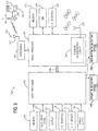
FIG. 3 is a block diagram of the mobile computing device ofFIGs. 1 and 2 , according to an exemplary embodiment. -
FIG. 4 is a block diagram of a system for displaying image data and geographic element data, according to an exemplary embodiment. -
FIG. 5 is a flowchart illustrating a method for displaying image data and geographic element data, according to an exemplary embodiment. -
FIG. 6 is a schematic view of a mobile computing device, according to an exemplary embodiment. -
FIG. 7 is a graphic and three screens illustrating a system and method for displaying image data and geographic element data, according to an exemplary embodiment. -
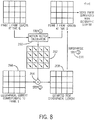
FIG. 8 is a flow diagram illustrating an image processing system and method, according to an exemplary embodiment. -
FIG. 9 is a block diagram of the mobile computing device ofFIGs. 1, 2 , and3 , according to an exemplary embodiment. -
FIG. 10 is a flow diagram illustrating a process of displaying geographic element data based on personal data. -
FIG. 11 is an image illustrating the misalignment of video frame from camera and geographic element frame. -
Fig. 12 is a flow diagram illustrating the steps of aligning geographic element frame to video frame. -
FIG. 13 is a block diagram of a device configured to determine orientation of the device. -
FIG. 14 is a flow diagram illustrating a process of determining the orientation. - There is a need for an improved system and method for displaying geographic elements on a display of a computing device, such as a mobile computing device. Further, there is a need for a system and method which display geographic elements based at least in part on orientation of the device and/or a direction in which the user of the device is facing. Further still, there is a need for a system and method which display geographic elements based at least in part on updated or instantaneous orientation data as a user of the device changes the direction the user or device is facing. Further still, there is a need for a system and method configured to enable a user to point a mobile computing device at a location or geographic element and get information about the geographic element (e.g., street name, landmark, etc.).
- Referring first to
FIG. 1 , amobile computing device 100 is shown.Device 100 is a smart phone, which is a combination mobile telephone and handheld computer having personal digital assistant functionality. The teachings herein can be applied to other mobile computing devices (e.g., a laptop computer, digital camera, camera phone, personal navigation device, etc.) which may be configured to be carried by a user while in use or other electronic devices (e.g., a desktop personal computer, etc.). Personal digital assistant functionality can comprise one or more of personal information management functions (e.g., e-mail, calendar, contacts/address book, notes, bookmarks, favorites, etc.), database functions, word processing, spreadsheets, voice memo recording, etc. and may be configured to synchronize personal information from one or more applications with a computer 132 (e.g., desktop, laptop, remote networked server, etc.).Device 100 may comprise a general purpose microprocessor which is further configured to receive and operate additional applications provided todevice 100 after manufacture, e.g., via wired or wireless download, SecureDigital card, etc. -
Device 100 comprises ahousing 11 having afront side 13 and a back side 17 (FIG. 2 ). Anearpiece speaker 15, aloudspeaker 16, and a user input device are coupled tohousing 11.Housing 11 is configured to hold a screen in a fixed or slidable relationship above a user input device in a substantially parallel or same plane as the user input device. This fixed or slidable relationship excludes a hinged relationship between the screen and plurality of keys.Device 100 may be a handheld computer, which is a computer small enough to be carried in a typical front pocket found in a pair of pants, comprising such devices as typical mobile telephones, personal digital assistants, and some digital cameras, but excluding typical laptop computers, tablet PCs, and larger digital cameras. In alternative embodiments,display 112,user input device 110,earpiece 15 andloudspeaker 16 may each be positioned anywhere onfront side 13,back side 17 or the edges therebetween. - In
various embodiments device 100 has a width (shorter dimension) of no more than about 200 mm or no more than about 100 mm. According to some of these embodiments,housing 11 has a width of no more than about 85 mm or no more than about 65 mm. According to some embodiments,housing 11 has a width of at least about 30 mm or at least about 50 mm. According to some of these embodiments,housing 11 has a width of at least about 55 mm. - In some embodiments,
housing 11 has a length (longer dimension) of no more than about 200 mm or no more than about 150 mm. According to some of these embodiments,housing 11 has a length of no more than about 135 mm or no more than about 125 mm. According to some embodiments,housing 11 has a length of at least about 70 mm or at least about 100 mm. According to some of these embodiments,housing 11 has a length of at least about 110 mm. - In some embodiments,
housing 11 has a thickness (smallest dimension) of no more than about 150 mm or no more than about 50 mm. According to some of these embodiments,housing 11 has a thickness of no more than about 30 mm or no more than about 25 mm. According to some embodiments,housing 11 has a thickness of at least about 10 mm or at least about 15 mm. According to some of these embodiments,housing 11 has a thickness of at least about 50 mm. - In some embodiments,
housing 11 has a volume of up to about 2500 cubic centimeters and/or up to about 1500 cubic centimeters. In some of these embodiments,housing 11 has a volume of up to about 1000 cubic centimeters and/or up to about 600 cubic centimeters. - While described with regards to a hand-held device, many embodiments are usable with portable devices which are not handheld and/or with non-portable devices/systems.
-
Device 100 may provide voice communications functionality in accordance with different types of cellular radiotelephone systems. Examples of cellular radiotelephone systems may include Code Division Multiple Access (CDMA) cellular radiotelephone communication systems, Global System for Mobile Communications (GSM) cellular radiotelephone systems, etc. - In addition to voice communications functionality,
device 100 may be configured to provide data communications functionality in accordance with different types of cellular radiotelephone systems. Examples of cellular radiotelephone systems offering data communications services may include GSM with General Packet Radio Service (GPRS) systems (GSM/GPRS), CDMA/1xRTT systems, Enhanced Data Rates for Global Evolution (EDGE) systems, Evolution Data Only or Evolution Data Optimized (EV-DO) systems, etc. -
Device 100 may be configured to provide voice and/or data communications functionality in accordance with different types of wireless network systems. Examples of wireless network systems may further include a wireless local area network (WLAN) system, wireless metropolitan area network (WMAN) system, wireless wide area network (WWAN) system, and so forth. Examples of suitable wireless network systems offering data communication services may include the Institute of Electrical and Electronics Engineers (IEEE) 802.xx series of protocols, such as the IEEE 802.1 1a/b/g/n series of standard protocols and variants (also referred to as "WiFi"), the IEEE 802.16 series of standard protocols and variants (also referred to as "WiMAX"), the IEEE 802.20 series of standard protocols and variants, a wireless personal area network (PAN) system, such as a Bluetooth system operating in accordance with the Bluetooth Special Interest Group (SIG) series of protocols. - As shown in the embodiment of
FIG. 3 ,device 100 comprises aprocessing circuit 101 which may comprise a dual processor architecture including ahost processor 102 and a radio processor 104 (e.g., a base band processor). Thehost processor 102 and theradio processor 104 may be configured to communicate with each other usinginterfaces 106 such as one or more universal serial bus (USB) interfaces, micro-USB interfaces, universal asynchronous receiver-transmitter (UART) interfaces, general purpose input/output (GPIO) interfaces, control/status lines, control/data lines, shared memory, and so forth. - The
host processor 102 may be responsible for executing various software programs such as application programs and system programs to provide computing and processing operations fordevice 100. Theradio processor 104 may be responsible for performing various voice and data communications operations fordevice 100 such as transmitting and receiving voice and data information over one or more wireless communications channels. Although embodiments of the dual processor architecture may be described as comprising thehost processor 102 and theradio processor 104 for purposes of illustration, the dual processor architecture ofdevice 100 may comprise additional processors, may be implemented as a dual- or multi-core chip with bothhost processor 102 andradio processor 104 on a single chip, etc. Alternatively,processing circuit 101 may comprise any digital and/or analog circuit elements, comprising discrete and/or solid state components, suitable for use with the embodiments disclosed herein. - In various embodiments, the
host processor 102 may be implemented as a host central processing unit (CPU) using any suitable processor or logic device, such as a general purpose processor. Thehost processor 102 may comprise, or be implemented as, a chip multiprocessor (CMP), dedicated processor, embedded processor, media processor, input/output (I/O) processor, co-processor, a field programmable gate array (FPGA), a programmable logic device (PLD), or other processing device in alternative embodiments. - The
host processor 102 may be configured to provide processing or computing resources todevice 100. For example, thehost processor 102 may be responsible for executing various software programs such as application programs and system programs to provide computing and processing operations fordevice 100. Examples of application programs may include, for example, a telephone application, voicemail application, e-mail application, instant message (IM) application, short message service (SMS) application, multimedia message service (MMS) application, web browser application, personal information manager (PIM) application, contact management application, calendar application, scheduling application, task management application, word processing application, spreadsheet application, database application, video player application, audio player application, multimedia player application, digital camera application, video camera application, media management application, a gaming application, and so forth. The application software may provide a graphical user interface (GUI) to communicate information betweendevice 100 and a user. - System programs assist in the running of a computer system. System programs may be directly responsible for controlling, integrating, and managing the individual hardware components of the computer system. Examples of system programs may include, for example, an operating system (OS), device drivers, programming tools, utility programs, software libraries, an application programming interface (API), graphical user interface (GUI), and so forth.
Device 100 may utilize any suitable OS in accordance with the described embodiments such as a Palm OS®, Palm OS® Cobalt, Palm WebOS, Microsoft® Windows OS, Microsoft Windows® CE, Microsoft Pocket PC, Microsoft Mobile, Symbian OS™, Embedix OS, Linux, Binary Run-time Environment for Wireless (BREW) OS, JavaOS, a Wireless Application Protocol (WAP) OS, and so forth. -
Device 100 may comprise amemory 108 coupled to thehost processor 102 and amemory 124 coupled toradio processor 104.Device 100 may be configured to wirelessly access amemory 152 coupled to aremote computer 132. In various embodiments, thememory host processor 102 orradio processor 104.Memories - Although
memory host processor 102 andradio processor 104 for purposes of illustration, in various embodiments some portion or theentire memory 108 may be included on the same integrated circuit as thehost processor 102. Alternatively, some portion or theentire memory host processor 102. In various embodiments,device 100 may comprise an expansion slot to support a multimedia and/or memory card, for example, andmemory -
Device 100 comprises auser input device 110 coupled to thehost processor 102. Theuser input device 110 may comprise, for example, a QWERTY key layout and an integrated number dial pad.Device 100 also may comprise various keys, buttons, and switches such as, for example, input keys, preset and programmable hot keys, left and right action buttons, a navigation button such as a multidirectional navigation button, phone/send and power/end buttons, preset and programmable shortcut buttons, a volume rocker switch, a ringer on/off switch having a vibrate mode, a keypad, an alphanumeric keypad, a touch screen, a touch pad, a speech or voice recognition device, and so forth. - The
host processor 102 may be coupled to adisplay 112. Thedisplay 112 may comprise any suitable visual interface for displaying content to a user ofdevice 100. For example, thedisplay 112 may be implemented by a liquid crystal display (LCD) such as a touch-sensitive color (e.g., 16-bit color) thin-film transistor (TFT) LCD screen. In some embodiments, the touch-sensitive LCD may be used with a stylus and/or a handwriting recognizer program. -
Device 100 may comprise an input/output (I/O)interface 114 coupled to thehost processor 102 and a I/O interface 128 coupled to the radio processor. I/O interfaces 114, 128 may comprise one or more I/O devices such as a serial connection port, an infrared port, integrated Bluetooth® wireless capability, and/or integrated 802.11x (WiFi) wireless capability, to enable wired (e.g., USB cable) and/or wireless connection to a local computer system, such as a local personal computer (PC). In various implementations,device 100 may be configured to transfer and/or synchronize information with the local computer system. - The
host processor 102 may be coupled to various audio/video (A/V)devices 116 that support A/V capability ofdevice 100. Examples of A/V devices 116 may include, for example, a microphone, one or more speakers, an audio port to connect an audio headset, an audio coder/decoder (codec), an audio player, a digital camera, a video camera, a video codec, a video player, and so forth. - The
host processor 102 may be coupled to apower supply 118 configured to supply and manage power to the elements ofdevice 100. In various embodiments, thepower supply 118 may be implemented by a rechargeable battery, such as a removable and rechargeable lithium ion battery to provide direct current (DC) power, and/or an alternating current (AC) adapter to draw power from a standard AC main power supply. -
Device 100 may comprise atransceiver 120 coupled to theradio processor 104. Thetransceiver 120 may comprise one or more transceivers configured to communicate using different types of protocols, communication ranges, operating power requirements, RF sub-bands, information types (e.g., voice or data), use scenarios, applications, and so forth. - The
transceiver 120 may be implemented using one or more chips as desired for a given implementation. Although thetransceiver 120 may be shown as being separate from and external to theradio processor 104 for purposes of illustration, in various embodiments some portion or theentire transceiver 120 may be included on the same integrated circuit as theradio processor 104. -
Device 100 may comprise anantenna system 122 for transmitting and/or receiving electrical signals. As shown, theantenna system 122 may be coupled to theradio processor 104 through thetransceiver 120. Theantenna system 122 may comprise or be implemented as one or more internal antennas and/or external antennas. -
Device 100 may comprise a subscriber identity module (SIM) 126 coupled to theradio processor 104. TheSIM 126 may comprise, for example, a removable or non-removable smart card configured to encrypt voice and data transmissions and to store user-specific data for allowing a voice or data communications network to identify and authenticate the user. TheSIM 126 also may store data such as personal settings specific to the user. -
Device 100 may comprise one or more magnetic detectingdevices 177 and/or non-magnetic detectingdevices 179. Magnetic-detectingdevice 177 may be configured to measure orientation ofdevice 100 by detecting a magnetic field; non-magnetic-detectingdevice 179 may be configured to measure the orientation or change in orientation ofdevice 100. Examples of a magnetic detecting device may include a compass, a magnetometer, an electronic compass, etc.. Examples of non-magnetic-detecting devices include a gyroscope, an electronic gyroscope, an accelerometer, a camera, a GPS receiver or circuit, a proximity sensor, a speaker or audio input, a light sensor, etc.. - In accordance with one or more embodiments of the invention,
device 100 comprises location or position determination capabilities.Device 100 may employ one or more location determination techniques including, for example, Global Positioning System (GPS) techniques, Cell Global Identity (CGI) techniques, CGI including timing advance (TA) techniques, Enhanced Forward Link Trilateration (EFLT) techniques, Time Difference of Arrival (TDOA) techniques, Angle of Arrival (AOA) techniques, Advanced Forward Link Trilateration (AFTL) techniques, Observed Time Difference of Arrival (OTDOA), Enhanced Observed Time Difference (EOTD) techniques, Assisted GPS (AGPS) techniques, hybrid techniques (e.g., GPS/CGI, AGPS/CGI, GPS/AFTL or AGPS/AFTL for CDMA networks, GPS/EOTD or AGPS/EOTD for GSM/GPRS networks, GPS/OTDOA or AGPS/OTDOA for UMTS networks), etc. -
Device 100 may be configured to receive location data and associate the location data with a digital image captured bydevice 100 or for use with other applications, such as navigation applications.Device 100 comprises a local position determination circuit 134 (e.g., a GPS receiver) which may be integrated within housing 11 (FIG. 1 ) configured to receive satellite data via anantenna 135 and to calculate a position fix. Local position determination circuit may alternatively comprise a GPS receiver in a second housing separate fromhousing 11 but in the vicinity ofdevice 100 and configured to communicate withdevice 100 wirelessly (e.g., via a PAN, such as Bluetooth).Device 100 may be configured to communicate over a radio access network 130 (e.g., UMTS radio access network) with the remote computer 132 (e.g., a location determination entity (PDE), a location proxy server (LPS) and/or a mobile positioning center (MPC), etc.). - When assisting the
mobile computing device 100, theremote computer 132 may handle various processing operations and also may provide information to aid location determination. Examples of position assist data may include satellite-based measurements, terrestrial-based measurements, and/or system-based measurements such as satellite almanac information, GPS code phase measurements, ionospheric data, ephemeris data, time correction information, altitude estimates, timing offsets, forward/reverse link calibration, coarse data, and so forth. - The
host processor 102 may comprise and/or implement at least one LBS (location-based service) application. In general, the LBS application may comprise any type of client application executed by thehost processor 102, such as a GPS application, configured to communicate location requests (e.g., requests for position fixes) and location responses. Examples of LBS applications include, without limitation, wireless 911 emergency services, roadside assistance, asset tracking, fleet management, friends and family locator services, dating services, and navigation services which may provide the user with maps, directions, routing, traffic updates, mass transit schedules, information regarding local points-of-interest (POI) such as restaurants, hotels, landmarks, and entertainment venues, and other types of LBS services in accordance with the described embodiments. - Referring now to
FIG. 4 , a system for displaying image data and geographic element data will be described. Some or all of the geographic element data may be stored onmemory device 100 and/ormemory 152 located on remote computer 132 (FIG. 1 ). In embodiments wherein geographic element data is stored onmemory memory 152 onremote computer 132. Acamera 150 may be coupled (e.g., wired or wirelessly) toprocessing circuit 101, and is configured to output image data (photographic data of a person or thing, e.g., video data, digital still image data, etc.) toprocessing circuit 101.Position determination circuit 134 anduser input device 110 may also be coupled toprocessing circuit 101. - In this embodiment,
memory - Referring now to
FIG. 9 ,device 100 is connected with a computer that is configured to be connected with the Internet.Computer 132 may be connected with the Internet using any technologies. Examples of such technologies include copper wires, fiber-optic cables and wireless connections.Processing circuit 101 can be connected withcomputer 132 using any methods. In one example,device 100 may be connected withcomputer 132 using wireless connections. In another example,device 100 sits in a cradle which is connected withcomputer 132. In yet another example,device 100 andcomputer 132 are both connected with the Internet, and they communicate with each other through the Internet. - In one exemplary embodiment,
computer 132 is a server maintained by the company providing geographic element data.Memory 152 may store a database of the geographic element data for the one or more geographic elements. In another exemplary embodiment,computer 132 may be any computer that is configured to share geographic element data over the Internet, maintained by any person or entity. -
Processing circuit 101 is configured to receive the geographic element data for the one or more geographic elements, to determine the orientation ofcamera 150, and to concurrently display the image data and geographic element data for the one or more geographic elements ondisplay 112. The data types may be presented one after another (e.g., the image data followed by the geographic element data, the geographic element data followed by the image data, etc.) or at substantially the same time. The data types may be presented on a single software display screen, and may be presented substantially simultaneously. Geographic element data may be displayed in proximity to, on top of, aligned with, or adjacent to a geographic element shown in the image data. - In one embodiment,
processing circuit 101 may be configured to determine or estimate the orientation or direction ofcamera 150 ordevice 100 at least in part via an image processing algorithm. The image processing algorithm may be configured to compare a first image to a second, subsequent image, to identify portions of the images representing a movement of an object in the image, and determine an orientation change of the camera based on the identified portions representing movement. An exemplary image processing algorithm is described below with reference toFIGs. 7 and8 . - According to the invention,
processing circuit 101 is configured to determine the orientation ofcamera 150 in part viaposition determination circuit 134.Processing circuit 101 may determine the orientation ofcamera 150 by usingposition determination circuit 134 to compare the device position at a first time with the device position at a second time. According to an embodiment of the invention,processing circuit 101 determines the orientation ofcamera 150 in part via user input fromuser input device 110, wherein the user provides the orientation to device 100 (e.g., cardinal or intercardinal or other orientation data, facing a particular geographic element, etc.). In an embodiment not covered by the invention, a compass, gyroscope, or other directional indication device may alternatively provide the orientation ofcamera 150. In still other alternative embodiments, two or more of these systems for determining the orientation ofcamera 150 may be used in combination. For example,processing circuit 101 may determine the initial orientation ofcamera 150 via user input fromuser input device 110 or positional data fromposition determination circuit 134, and may determine any subsequent changes in the orientation ofcamera 150 via an image processing algorithm. -
Processing circuit 101 is configured to concurrently display the image data received fromcamera 150 and geographic element data received frommemory display 112.Processing circuit 101 may be configured to determine the geographic element data to display based in part on a field of view ofcamera 150, as indicated by the orientation data and/or current position data.Processing circuit 101 may be configured to display only geographic element data representing geographic elements within the field of view ofcamera 150. Alternatively,processing circuit 101 may be configured to display directional indicators representing the relative position of geographic elements not within the field of view ofcamera 150.Processing circuit 101 may determine whether a geographic element is within the field of view ofcamera 150 by comparing the orientation ofcamera 150 with position and size data for the geographic element. - In another embodiment,
processing circuit 101 may be configured to select geographic element data based at least in part on device position data fromposition determination circuit 134.Processing circuit 101 may be configured to select geographic element data only for geographic elements within a set distance from the device position. In another embodiment,processing circuit 101 may be configured to select geographic element data only for geographic elements within a distance selected by a user viauser input device 110. - In yet another embodiment,
processing circuit 101 may be configured to display one or more geographic elements in a first mode, and in a second mode enable a user to select geographic element data for one or more of the geographic elements for display concurrently with the image data. In the second mode, a user may limit the geographic element data that is displayed by usinguser input device 110 to select geographic element data for one or more of the geographic elements. Theprocessing circuit 101 is configured to selectively display geographic element data of the one or more geographic elements based on instructions from the user. The user may communicate the instructions todevice 100 throughinput device 110. Instructions from the user can be any instructions reflecting the intent of the user on what geographic element data is to be displayed. A user may select geographic element data using one or more possible selection methods, such as touching the one or more geographic elements ondisplay 112 ifdisplay 112 is touch-sensitive, selecting geographic element data using a key pad or one or more buttons, selecting geographic element data using voice commands, and other selection methods.Processing circuit 101 may be configured to display geographic element data in the second mode only if it has been selected by a user. In one embodiment, a user may select whether to display the geographic element data in the first mode or the second mode. - In another embodiment,
processing circuit 101 may be configured to receive user input for a specific geographic element to be found. For example,circuit 101 may be configured to send display data to the display in the form of a search bar or other input field. User input data may be received at the search bar, such as "closest Starbucks" or "Sears Tower."Circuit 101 may then be configured to generate or receive location data for the request geographic element or point of interest.Circuit 101 may then receive the current location and/or orientation ofdevice 100.Circuit 101 may then calculate a direction and/or distance fromdevice 100 to the point of interest and may further display one or more arrows on the display to direct the user to an orientation that will pointdevice 100 toward the requested geographic element. When viewed through the camera ofdevice 100, the geographic element will be found and can be overlayed with geographic element data as described herein. - In another embodiment,
processing circuit 101 may be configured to display a distinguishing indicia which distinguishes at least one of the geographic elements from another of the geographic elements. The distinguishing indicia may be a geometric shape such as a rectangle or oval surrounding part or all of the geographic element, an alteration of color, contrast or brightness, an arrow or other directional indicator, a blinking indicator, or other distinguishing indicia. In one exemplary embodiment,processing circuit 101 may be configured to display distinguishing indicia for all geographic elements within the field of view ofcamera 150 for which geographic element data is available. In another exemplary embodiment,processing circuit 101 may be configured to display distinguishing indicia for one or more geographic elements based at least in part on the geographic element data (e.g., highlight all streets, all buildings, all geographic elements on a particular street, etc.). In yet another exemplary embodiment,processing circuit 101 may be configured to allow a user to select one or more geographic elements to distinguish with distinguishing indicia viauser input device 110. - According to another exemplary embodiment,
memory processing circuit 101 may be configured to receive the geographic element data for the one or more geographic elements, determine the orientation ofcamera 150, and concurrently display image data received fromcamera 150 and geographic element data ondisplay 112. In this embodiment, as the camera orientation changes,processing circuit 101 is configured to move the geographic element data on the display in at least two dimensions, such as for example the horizontal and vertical directions. The geographic element data in this embodiment may maintain a positional relationship with image data on the display as the camera orientation changes.Processing circuit 101 may accomplish this by assigning display coordinates to the geographic element data and updating the coordinates as the orientation ofcamera 150 changes. The geographic element data may comprise textual image, video and/or audio data.Processing circuit 101 may be configured to determine the orientation ofcamera 150 at least in part via an image processing algorithm.Processing circuit 101 may also be configured to select the geographic element data based at least in part on device position data provided byposition determination circuit 134. - Referring now to
FIG. 5 , an exemplary method of providing displaying image and geographic element data will be described. Atstep 170, the method comprises outputting image data from a camera and receiving the image data in aprocessing circuit 101 of a mobile computing device. Atstep 172, the method comprises storing geographic element data representing geographic elements in a memory, and receiving the geographic element data from memory in theprocessing circuit 101. Atstep 174, the method comprises determining the orientation of the camera. Atstep 176, the method comprises concurrently displaying the image data and geographic element data on a display. For example, the method may comprise displaying image data and geographic element data for a certain building. The method may comprise receiving an image of the building from a camera, receiving the name and address of the building from a memory, determining the orientation of the camera, and concurrently displaying the image of the building and text representing the name and address of the building. - According to another exemplary embodiment,
processing circuit 101 may be configured to receive an image fromcamera 150 and extract data from the image and save the extracted data as part of the geographic element data for a geographic element.Processing circuit 101 may extract data from the image using optical character recognition (OCR) or another method of data extraction from an image. In one embodiment,camera 150 may be used to capture an image of a street sign, billboard, or other signage andprocessing circuit 101 may extract the words from the image. - According to another exemplary embodiment, the image data from the camera may be displayed along with the geographic element data in real time. The camera may output image data, such as digital still images, a video camera feed or live video, or other images.
- According to another exemplary embodiment,
processing circuit 101 may be configured to superimpose navigational information or geographic elements data on a video camera display when a camera application operable oncircuit 101 is enabled by the user or when a dedicated application is enabled by the user. - Referring now to
FIG. 6 , a screen display is shown according to an exemplary embodiment.Screen display 200 comprises aborder 202 illustrating a variety oficons 204 relating to wireless telephony, battery life, time of day, etc. In animage area 206 ofscreen display 200, an image fromcamera 150 is shown. In this exemplary embodiment, geographic element data is concurrently displayed with the image (e.g., overlayed, superimposed, etc.) in a few exemplary forms. Geographic element data for buildings are shown at indicia 208 (U.S. Bank) and 210 (Sears Tower).Indicia 208 comprises geographic element text data enclosed in a rectangular border disposed adjacent, overlapping, ornear image data 212 associated with the U.S. Bank building.Indicia 210 comprises geographic element text data enclosed in an oval border disposed adjacent, overlapping, ornear image data 214 associated with the Sears Tower building. The oval border can be indicative of a characteristic of the geographic element (e.g., the Sears Tower is some distance away, or disposed on or near a horizon line), or may be an alternative graphical way to display geographic text data.Indicia 214 shows street data (e.g. Main Street) which may be disposed on or near a street sign in the image data or on a street as shown atindicia 218. Alternatively,street sign 216 may be a graphical element generated by processingcircuit 101 overlayed on the image data to show the name of the street. Anindicia 220 is disposed in a proximate vertical location to illustrate a nearby geographic element (e.g., a Mobil gas station), along with an arrow indicating the direction of the nearby geographic element. - According to one exemplary embodiment, as the user changes the orientation of
display 200, the image data and geographic element data (represented by the indicia) will move as well, and new image data and corresponding geographic element data may be presented ondisplay screen 200. - According to another exemplary embodiment, the indicia may change in color or size to indicate proximity, point of interest, preselected destination, etc.
- Referring now to
FIG. 7 , a system and method for displaying image data and geographic element data will be described, according to another exemplary embodiment.Graphic 230 is a schematic diagram of an exemplary geographic location having geographic elements comprising abuilding 232, afirst street 234, and asecond street 236. Anarrow 238 indicates North and an X indicates a positions at which a user is usingdevice 100. Adotted arrow 240 indicates an initial direction that a camera ondevice 100 is facing. - In this exemplary embodiment, displaying the image data and geographic element data comprises a first phase in which the camera is aligned. Alignment is performed initially when the application is switched on, every
time device 100 loses alignment, or at other times. In a second phase,device 100 is configured to retrieve geographic element data and superpose the geographic element data on the image data from the camera. The second phase may be performed for every video frame generated by the camera. - In the camera alignment phase, an application running on
processing circuit 101 will retrieve the current geographical position ofdevice 100, retrieve a default orientation from memory (e.g., North), and superpose, superimpose, overlay, or display concurrently a camera image and the geographical element data which would be in the camera view if the camera is facing in the default orientation.Screen 242 illustrates a geographic element frame or image before alignment, which comprises geographic element data for abuilding 244 and two streetgeographic elements optional edges 250 of the graphic element frame.Screen 244 illustrates the geographic element frame superposed on the camera image when the camera is facing the initial orientation ordirection 240, before alignment.Elements buildings street 236, and surrounding geographic elements. - Next, the user may pan the camera and the user aligns the instantaneous video frame with the superposed geographical element data, until the screen appears as shown in
screen 254.Processing circuit 101 may configure a button, soft key, or other shortcut key to receive an indication from the user as to when the video frame is aligned with the superposed geographic element data. For example, acenter button 113 of a 5-way navigation system 115 may be the shortcut key.Processing circuit 101 may be configured to receive an indication from the user via the shortcut key to make the application determine that the video or camera frame is aligned to the geographical element data. The application will then proceed to the second phase. - During the geographical element retrieval and superposition phase, frames of motion vectors may be calculated continuously between successive video frames, as will be described below with reference to
FIG. 8 .Processing circuit 101 may be configured to apply these motion vectors to the current geographical element frame to estimate the new geographical element frame, and the geographical element data that should comprise the new geographical element frame. The new geographical element frame may be superimposed on the current video frame. - In case there is misalignment, for example when the current geographical element data and the current video frame do not match, the application may be configured to retrieve the north facing geographical element and the process may be repeated, which step may occur manually or automatically.
-
FIG. 11 illustrates the effect of misalignment between the geographical element frame and the current video frame.Buildings Buildings Buildings Buildings device 100, the inexact orientation ofdevice 100, that the positions of geographic element received from the computer is not precise, etc.. -
FIG. 8 illustrates a flow diagram showing an exemplary image processing algorithm. The algorithm may be operable onprocessing circuit 101 during the second phase described above. At astep 260, video frames from the camera at times t1 and t2, which may be successive video frames or other video frames at different times, are partitioned into a plurality of macro blocks (e.g., 8 by 8, or other numbers) and compared. For each macro block from the old frame at t1, processingcircuit 101 is configured to calculate a correlation with the 8 neighboring macro blocks in the new frame at t2. The neighboring block with highest correlation is recorded.Processing circuit 101 is then configured to calculate or determine a motion vector corresponding to the neighboring macro block with the highest correlation. The motion vector may be of the form (x,y) where x and y can take one of three values (-1, 0, 1). Hence, 8 possible motion vectors can be generated per macro block depending upon the direction of motion. Motion vectors are generated for the entire frame or at least a portion of the frame to provide themotion vector matrix 262. Alternatively, other methods may be used to calculatemotion vector matrix 262 or to determine the orientation change ofdevice 100. - At
step 264, a newgeographic element frame 268 is provided based on the firstgeographic element frame 266 and themotion vector matrix 262. Geographic element data is retrieved from memory as needed and reoriented or repositioned as needed to create newgeographic element frame 268.New frame 268 is then superimposed atstep 270 on new frame at t2. At step 272, the display screen ofdevice 100 is updated with the video frame from the camera superimposed with the newgeographic element frame 268. -
Fig. 12 illustrates the steps of aligning corresponding geographic element data received from thecomputer 132 to the displayed geographic element.Processing circuit 101 is configured to identify or determine where one or more corners of buildings are and determine a reference or alignment data or indicator.Processing circuit 101 is configured to detect boundaries, edges and/or corners of the displayed geographic element and determine a reference (step 1201).Processing circuit 101 receives boundary, edge, corner and/or positioning information of geographic elements frommemory 108,memory 124, orcomputer 132. Atstep 1202,processing circuit 101 receives the boundary, edge and/or position information of the geographic elements. Atstep 1203,processing circuit 101 determines the corresponding images to the geographic element. Atstep 1204,processing circuit 101 may display geographic element data near the corresponding images in display. Alternatively, this data can be stored in memory for comparison without displaying it. Theprocessing circuit 101 may compare the boundaries, edges, corners and/or positions of the image to the information received from thecomputer 132. The alignment process illustrated inFig. 12 can augment the sensor and GPS to improve the accuracy of positions of geographic elements. In one embodiment, theprocessing circuit 101 assigns a geographic element received from thecomputer 132 to a geographic element image received from the camera based on relative positions, shapes and/or sizes of the geographic elements. - In one exemplary embodiment, the
processing circuit 101 is configured to detect the boundaries and/or edges of the displayed geographic element by detecting sharp changes in image brightness. Theprocessing circuit 101 may employ an edge detection or edge discrimination algorithm to identify points in the image. The purpose of detecting sharp changes in image brightness is to capture important events and changes in properties of the scene. Under assumptions for an image formation model, discontinuities in image brightness are likely to correspond to: discontinuities in depth, discontinuities in surface orientation, changes in material properties and variations in scene illumination. One effect of using an edge detection/edge discrimination algorithm is enhancing the accuracy fordevice 100 to recognize whatgeographic element device 100 is pointed at. For example, when auser points device 100 at a restaurant versus the one right next to it,device 100 can discriminate whichrestaurant device 100 is pointed at with greater accuracy. -
FIG. 10 illustrates a process of displaying geographic element data based on personal data of the user of the mobile computing device. In one exemplary embodiment, theprocessing circuit 101 is configured to display geographic element data for the one or more geographic elements based on personal data of the user of the mobile computing device. Atstep 1001,processing circuit 101 retrieves personal data frommemory computer 132. Atstep 1002,processing circuit 101 receives geographic element data. Atstep 1003,processing circuit 101 decides what geographic element data is displayed based on personal data. For example, if the user is a member of AAA (American Automobile Association) or local radio station or local club that gives discounts, the discount information for members may be shown as geographic element data displayed on or near the building of that entity. The sequence ofstep 1001, receiving personal data, andstep 1002, receiving geographic element data can be switched. - Personal data can be any data related to the user. Examples of personal data include, names of the users, addresses of the users, photos that the user previously stored, memberships and affiliations of the users in any entities, PIM (personal information management) data, financial data, any personal information of the user, etc. Personal data may comprise an employee identification or other corporate identification information which indicates a user has one or more levels of access within a corporate campus. Personal data can also be configured to be geographic element data. For example, after a photo of a friend is stored by the user, when a user drives by the friend's house, the picture of the friend can be shown as geographic element data together with the image of the house.
-
FIG. 13 illustrates a device that comprises a magnetic-detecting device configured to measure orientation of the device by detecting a magnetic field; a non-magnetic-detecting device configured to measure the orientation or change in orientation of the device; a processing circuit configured to determine the orientation of the device using measurement of the magnetic-detecting device and to switch to using orientation measurement of the non-magnetic-detecting device based on information from the magnetic-detecting device, non-magnetic-detecting device, and/or another data source. A magnetic-detecting device can be any device that measures orientation by detecting a magnetic field. Examples of a magnetic detecting device may include a compass, a magnetometer, an electronic compass, etc.. A non-magnetic-detecting device can be any device that measures orientation by a method other than detecting a magnetic field. Examples of non-magnetic-detecting devices include a gyroscope, an electronic gyroscope, an accelerometer, a camera, a GPS, a proximity sensor, a speaker or audio input, a light sensor, etc.. Orientation of device can mean the direction that a certain part of the device faces. For example, the orientation ofdevice 100 could be the direction which the camera faces. - The process of determining orientation of the device using the processing circuit is shown in
FIG. 14 , according to an exemplary embodiment. When the application is turned on or enabled,processing circuit 101 checks whether magnetic-detectingdevice 1301 is working properly. Ifprocessing circuit 101 determines that magnetic-detectingdevice 1301 is not working properly based on information from magnetic-detectingdevice 1301, it will receive orientation information from non-magnetic-detectingdevice 1302. For example,processing circuit 101 may decide that the magnetic field detected by magnetic-detectingdevice 1301 is too weak, or changing too fast from the orientation measured by non-magnetic-detecting-device 1302 and conclude that the orientation information from magnetic-device 1301 is not reliable. Ifprocessing circuit 101 determines that magnetic-detectingdevice 1301 is working properly,processing circuit 101 will use magnetic-detectingdevice 1301 to determine orientation.Processing circuit 101 may check the status of magnetic-detectingdevice 1301 periodically or constantly to decide whether to switch the orientation measuring device. - In one exemplary embodiment,
processing circuit 101 is configured to determine current location and display what geographic elements are around the current location.Device 100 may also display geographic element data related to displayed geographic elements, for example, writings or reviews (e.g., from an on-line review service such as San Francisco, California), user reviews, restaurant ratings or even health inspector reviews along with the image from the camera showing YELP, the related geographic element. In each of the scenarios described herein, the video and text data may be retrieved bydevice 100 from a remote sensor over a wireless connection, for example, whereindevice 110 sends location and/or orientation data and/or geographic element data to the remote server, and the server returns the reviews, ratings, or other data to be displayed concurrently with and/or in the proximity of the geographic element being viewed by the camera on the display ofdevice 100. - In one exemplary embodiment,
processing circuit 101 is configured to display movie times and ratings. Whendevice 100 is held close to a movie theater with the camera pointed to the theater, the movies may pop up on the display ofdevice 100 when in the camera view. A user may useinput device 110 to instructdevice 100 to show trailers or purchase tickets. - In one exemplary embodiment,
processing circuit 101 may change color or brightness of displayed geographic element data based on time of day or input data from a light sensor. In night time, the text of geographic element data is changed to light, whereas in day time, the text is changed to dark. This may be particularly useful in combination with overlaying street address information over a house to assist a user in finding a particular address at night. - In one exemplary embodiment,
processing circuit 101 is configured to display information useful for a political election or action group about the occupants of a house. Examples of geographic element data related to elections include voting information about the house, whether anyone from your organization has approached the house and the interaction of the occupants with your campaign (e.g. whether the occupants have made a donation). - In one exemplary embodiment,
processing circuit 101 is configured to display geographic element data related to utility and telecom services. For example, when an employee of a cable T.V. company drives by a house withdevice 100,device 100 may display a full history of all service calls, information on where the access box for cable is, what plan residents of the house are on and what equipment is in the house. Further, a plumber may see data about previous calls to the house, including what was fixed, what was charged, which parts were replaced, etc. - In one exemplary embodiment,
processing circuit 101 is configured to display geographic element data related to a landmark. Examples include guide information for that landmark, operating time of a museum, events coming up at the museum, and discount information based on the user's personal information such as memberships. - In one exemplary embodiment,
processing circuit 101 is configured to display geographic element data related to a retail store. Examples of geographic element data include opening hours, coupons, a link to current on-line or in store specials, what is on sale, and where goods are placed in the store. - In one exemplary embodiment,
processing circuit 101 is configured to display a map and schematics of the building when police or firefighters pointdevice 100 at a building. - In one exemplary embodiment,
processing circuit 101 is configured to display a schematic of where all wires and plumbing are and/or a virtual view of where things are connected. - In one exemplary embodiment,
processing circuit 101 is configured to display whether a bus/train is on time or running late whendevice 100 is pointed at a bus stop/train station. - In one exemplary embodiment,
processing circuit 101 is configured to display geographic element data related to a billboard whendevice 100 is pointed at the billboard. When the billboard shows "come watch SF Giants",device 100 is configured to display a schedule of games and a link to buy tickets. When the billboard shows an ad for a mall that is far away,device 100 is configured to display a link to download or display a map and directions to get to the mall. - In one exemplary embodiment,
processing circuit 101 is configured to display the image of a house, wherein the house glows when it finds the user's friend's house. In this case, the geographic element data is the owner of the house and the geographic element data is displayed by the house glowing or being otherwise highlighted, such as described hereinabove. - In one exemplary embodiment,
processing circuit 101 is configured to display wire-frame images of geographic elements. Wire-frame images may accurately reflect the boundaries, edges, corners and/or frames of the geographic element data. Wire-frame images may make discrimination of areas of interest easier. - With reference to the disclosure and claims, use of the phrase "based on" means "based at least in part on," and use of the term "a" or "an" means "one or more" or "at least one." Further, any of the steps of any of the methods disclosed herein may be combined with any of the other steps and/or rearranged with other steps in alternative embodiments, as long as the embodiments fall within the scope defined by the set of claims. Specifically, various embodiments falling within the scope of the set of claims may make use of different combinations of parts or all of the methods disclosed herein.
- While the exemplary embodiments illustrated in the FIGs., and described above are presently exemplary, it should be understood that these embodiments are offered by way of example only. For example, while exemplary embodiments are illustrated for use on mobile computing devices, the teachings herein may extend to use in other fields, such as automobiles, aircraft, etc. Accordingly, the present invention is not limited to a particular embodiment, but extends to various modifications that nevertheless fall within the scope of
claim 1.
Claims (8)
- A mobile computing device (100) comprising:a housing (11) configured to be carried by a user while in use;a camera (150) configured to output image data;a display (112);a position determination circuit (134);an input device (110), configured to receive instructions from a user; anda processing circuit (101);wherein the processing circuit (101) is configured to receive geographic element data for one or more geographic elements from a computer (132), to determine orientation of the camera using position data provided by the position determination circuit and user input indicating aligned superposition of the geographic element data with a corresponding geographic element displayed in an instantaneous video frame captured by the camera and rendered on the display, wherein the processing circuit is configured to detect a boundary and/or an edge of the displayed geographic element and align corresponding geographic element data received from the computer to the displayed geographic element based at least in part on a detected boundary and/or edge for the concurrent display of the image data and geographic element data for the one or more geographic elements on the display, and to concurrently display on the display the image data and geographic element data for geographic elements of the one or more geographic elements selected based at least in part on the position data.
- The mobile computing device of claim 1, wherein the processing circuit (101) is configured to display geographic element data for the one or more geographic elements based on personal data of a user of the mobile computing device (100).
- The mobile computing device (100) of claim 2, further comprising a memory (108, 124) storing personal data of the user; or
wherein the mobile computing device (100) is configured to receive personal data from the computer (132). - The mobile computing device of claim 1, wherein the processing circuit (101) is configured to selectively display geographic element data of the one or more geographic elements based on instructions from the user.
- The mobile computing device (100) of claim 1, wherein the processing circuit (101) is configured to display geographic element data of one geographic element selected by the user.
- The mobile computing device (100) of claim 1, wherein the geographic element data comprises textual, image, video and/or audio data.
- The mobile computing device (100) of claim 1, wherein the processing circuit (101) is configured to display a distinguishing indicia which distinguishes at least one of the geographic elements from another of the geographic elements.
- The mobile computing device (100) of claim 1, wherein the processing circuit (101) is configured to detect the boundary and/or an edge of the displayed geographic element by detecting sharp changes in image brightness.
Priority Applications (1)
| Application Number | Priority Date | Filing Date | Title |
|---|---|---|---|
| EP20167830.7A EP3693700A1 (en) | 2009-08-05 | 2010-07-21 | Displaying image data and geographic element data |
Applications Claiming Priority (2)
| Application Number | Priority Date | Filing Date | Title |
|---|---|---|---|
| US12/535,841 US9329052B2 (en) | 2007-08-07 | 2009-08-05 | Displaying image data and geographic element data |
| PCT/US2010/042743 WO2011016995A2 (en) | 2009-08-05 | 2010-07-21 | Displaying image data and geographic element data |
Related Child Applications (1)
| Application Number | Title | Priority Date | Filing Date |
|---|---|---|---|
| EP20167830.7A Division EP3693700A1 (en) | 2009-08-05 | 2010-07-21 | Displaying image data and geographic element data |
Publications (3)
| Publication Number | Publication Date |
|---|---|
| EP2462779A2 EP2462779A2 (en) | 2012-06-13 |
| EP2462779A4 EP2462779A4 (en) | 2017-09-27 |
| EP2462779B1 true EP2462779B1 (en) | 2020-04-15 |
Family
ID=43544838
Family Applications (2)
| Application Number | Title | Priority Date | Filing Date |
|---|---|---|---|
| EP10806832.1A Active EP2462779B1 (en) | 2009-08-05 | 2010-07-21 | Displaying image data and geographic element data |
| EP20167830.7A Pending EP3693700A1 (en) | 2009-08-05 | 2010-07-21 | Displaying image data and geographic element data |
Family Applications After (1)
| Application Number | Title | Priority Date | Filing Date |
|---|---|---|---|
| EP20167830.7A Pending EP3693700A1 (en) | 2009-08-05 | 2010-07-21 | Displaying image data and geographic element data |
Country Status (4)
| Country | Link |
|---|---|
| US (1) | US9329052B2 (en) |
| EP (2) | EP2462779B1 (en) |
| CN (1) | CN102804905B (en) |
| WO (1) | WO2011016995A2 (en) |
Families Citing this family (90)
| Publication number | Priority date | Publication date | Assignee | Title |
|---|---|---|---|---|
| US8994851B2 (en) * | 2007-08-07 | 2015-03-31 | Qualcomm Incorporated | Displaying image data and geographic element data |
| EP2215494A1 (en) * | 2007-11-30 | 2010-08-11 | Nokia Corporation | Controlling operation of a positioning module |
| US10095375B2 (en) * | 2008-07-09 | 2018-10-09 | Apple Inc. | Adding a contact to a home screen |
| US8494768B2 (en) * | 2008-07-31 | 2013-07-23 | Samsung Electronics Co., Ltd | Navigation system, method and database using mobile devices |
| US8908995B2 (en) | 2009-01-12 | 2014-12-09 | Intermec Ip Corp. | Semi-automatic dimensioning with imager on a portable device |
| DE102009037835B4 (en) * | 2009-08-18 | 2012-12-06 | Metaio Gmbh | Method for displaying virtual information in a real environment |
| US8682348B2 (en) * | 2009-11-06 | 2014-03-25 | Blackberry Limited | Methods, device and systems for allowing modification to a service based on quality information |
| KR20110051393A (en) * | 2009-11-10 | 2011-05-18 | 엘지전자 주식회사 | Mobile terminal and method for controlling the same |
| US9488488B2 (en) * | 2010-02-12 | 2016-11-08 | Apple Inc. | Augmented reality maps |
| TWI472717B (en) * | 2010-02-24 | 2015-02-11 | 私立中原大學 | Help with active navigation system |
| US20110211087A1 (en) * | 2010-02-26 | 2011-09-01 | Nokia Corporation | Method and apparatus providing for control of a content capturing device with a requesting device to thereby capture a desired content segment |
| KR101695812B1 (en) * | 2010-06-07 | 2017-01-23 | 엘지전자 주식회사 | Mobile terminal and method for controlling the same |
| US8706822B2 (en) | 2010-06-23 | 2014-04-22 | Microsoft Corporation | Delivering messages from message sources to subscribing recipients |
| KR101719982B1 (en) * | 2010-07-19 | 2017-03-27 | 엘지전자 주식회사 | Mobile terminal and method for controlling the same |
| US8634848B1 (en) * | 2010-09-29 | 2014-01-21 | Amazon Technologies, Inc. | Inter-device location determinations |
| US8818706B1 (en) | 2011-05-17 | 2014-08-26 | Google Inc. | Indoor localization and mapping |
| US8164599B1 (en) | 2011-06-01 | 2012-04-24 | Google Inc. | Systems and methods for collecting and providing map images |
| US8917902B2 (en) | 2011-08-24 | 2014-12-23 | The Nielsen Company (Us), Llc | Image overlaying and comparison for inventory display auditing |
| US20130061147A1 (en) * | 2011-09-07 | 2013-03-07 | Nokia Corporation | Method and apparatus for determining directions and navigating to geo-referenced places within images and videos |
| US8279716B1 (en) * | 2011-10-26 | 2012-10-02 | Google Inc. | Smart-watch including flip up display |
| CN103177030A (en) * | 2011-12-24 | 2013-06-26 | 富泰华工业(深圳)有限公司 | Referral information system and referral information method |
| US9170113B2 (en) | 2012-02-24 | 2015-10-27 | Google Inc. | System and method for mapping an indoor environment |
| US9500862B2 (en) * | 2012-03-13 | 2016-11-22 | Pioneer Corporation | Display information generating apparatus, display information generating method, a program for display information generating, and information recording medium |
| US9779546B2 (en) * | 2012-05-04 | 2017-10-03 | Intermec Ip Corp. | Volume dimensioning systems and methods |
| US9007368B2 (en) * | 2012-05-07 | 2015-04-14 | Intermec Ip Corp. | Dimensioning system calibration systems and methods |
| US10007858B2 (en) | 2012-05-15 | 2018-06-26 | Honeywell International Inc. | Terminals and methods for dimensioning objects |
| US10354004B2 (en) | 2012-06-07 | 2019-07-16 | Apple Inc. | Intelligent presentation of documents |
| US9870642B2 (en) * | 2012-08-10 | 2018-01-16 | Here Global B.V. | Method and apparatus for layout for augmented reality view |
| US10321127B2 (en) | 2012-08-20 | 2019-06-11 | Intermec Ip Corp. | Volume dimensioning system calibration systems and methods |
| US9939259B2 (en) | 2012-10-04 | 2018-04-10 | Hand Held Products, Inc. | Measuring object dimensions using mobile computer |
| US20140104413A1 (en) | 2012-10-16 | 2014-04-17 | Hand Held Products, Inc. | Integrated dimensioning and weighing system |
| WO2014074722A1 (en) * | 2012-11-07 | 2014-05-15 | Intertrust Technologies Corporation | Vehicle charging path optimization systems and methods |
| CN104995666B (en) | 2012-12-21 | 2019-04-23 | 苹果公司 | Method for indicating virtual information in true environment |
| EP2749843A1 (en) * | 2012-12-28 | 2014-07-02 | GN Store Nord A/S | Method for filtering and selecting geographical points of interest and mobile unit corresponding thereto |
| US9383218B2 (en) * | 2013-01-04 | 2016-07-05 | Mx Technologies, Inc. | Augmented reality financial institution branch locator |
| US9080856B2 (en) | 2013-03-13 | 2015-07-14 | Intermec Ip Corp. | Systems and methods for enhancing dimensioning, for example volume dimensioning |
| US9547917B2 (en) * | 2013-03-14 | 2017-01-17 | Paypay, Inc. | Using augmented reality to determine information |
| US9699375B2 (en) * | 2013-04-05 | 2017-07-04 | Nokia Technology Oy | Method and apparatus for determining camera location information and/or camera pose information according to a global coordinate system |
| US10368662B2 (en) | 2013-05-05 | 2019-08-06 | Trax Technology Solutions Pte Ltd. | System and method of monitoring retail units |
| US10228452B2 (en) | 2013-06-07 | 2019-03-12 | Hand Held Products, Inc. | Method of error correction for 3D imaging device |
| US9239950B2 (en) | 2013-07-01 | 2016-01-19 | Hand Held Products, Inc. | Dimensioning system |
| US9464885B2 (en) | 2013-08-30 | 2016-10-11 | Hand Held Products, Inc. | System and method for package dimensioning |
| US20150187101A1 (en) * | 2013-12-30 | 2015-07-02 | Trax Technology Solutions Pte Ltd. | Device and method with orientation indication |
| US10387996B2 (en) | 2014-02-02 | 2019-08-20 | Trax Technology Solutions Pte Ltd. | System and method for panoramic image processing |
| US10402777B2 (en) | 2014-06-18 | 2019-09-03 | Trax Technology Solutions Pte Ltd. | Method and a system for object recognition |
| US9823059B2 (en) | 2014-08-06 | 2017-11-21 | Hand Held Products, Inc. | Dimensioning system with guided alignment |
| KR20160041435A (en) | 2014-10-07 | 2016-04-18 | 엘지전자 주식회사 | Mobile terminal and control method for the mobile terminal |
| US10775165B2 (en) | 2014-10-10 | 2020-09-15 | Hand Held Products, Inc. | Methods for improving the accuracy of dimensioning-system measurements |
| US9779276B2 (en) | 2014-10-10 | 2017-10-03 | Hand Held Products, Inc. | Depth sensor based auto-focus system for an indicia scanner |
| US10810715B2 (en) | 2014-10-10 | 2020-10-20 | Hand Held Products, Inc | System and method for picking validation |
| US9897434B2 (en) | 2014-10-21 | 2018-02-20 | Hand Held Products, Inc. | Handheld dimensioning system with measurement-conformance feedback |
| US10060729B2 (en) | 2014-10-21 | 2018-08-28 | Hand Held Products, Inc. | Handheld dimensioner with data-quality indication |
| US9752864B2 (en) | 2014-10-21 | 2017-09-05 | Hand Held Products, Inc. | Handheld dimensioning system with feedback |
| US9557166B2 (en) | 2014-10-21 | 2017-01-31 | Hand Held Products, Inc. | Dimensioning system with multipath interference mitigation |
| US9762793B2 (en) | 2014-10-21 | 2017-09-12 | Hand Held Products, Inc. | System and method for dimensioning |
| CN105718470B (en) * | 2014-12-03 | 2019-08-20 | 高德软件有限公司 | A kind of POI data treating method and apparatus |
| CN104516968B (en) * | 2014-12-25 | 2018-10-23 | 济南市勘察测绘研究院 | A kind of automobile data recorder is applied to the method for geographical national conditions field operation verification |
| US9402162B1 (en) * | 2015-03-05 | 2016-07-26 | Htc Corporation | Mobile device, positioning method and non-transitor computer-readable recording medium |
| CN104713548A (en) * | 2015-03-30 | 2015-06-17 | 成都好飞机器人科技有限公司 | Automatic positioning method for air vehicle |
| US9786101B2 (en) | 2015-05-19 | 2017-10-10 | Hand Held Products, Inc. | Evaluating image values |
| US9927246B2 (en) * | 2015-05-27 | 2018-03-27 | Here Global B.V. | Method, apparatus and computer program product for providing navigation information in relation to augmented reality guidance |
| US10066982B2 (en) | 2015-06-16 | 2018-09-04 | Hand Held Products, Inc. | Calibrating a volume dimensioner |
| US20160377414A1 (en) | 2015-06-23 | 2016-12-29 | Hand Held Products, Inc. | Optical pattern projector |
| US9857167B2 (en) | 2015-06-23 | 2018-01-02 | Hand Held Products, Inc. | Dual-projector three-dimensional scanner |
| US9835486B2 (en) | 2015-07-07 | 2017-12-05 | Hand Held Products, Inc. | Mobile dimensioner apparatus for use in commerce |
| EP3118576B1 (en) | 2015-07-15 | 2018-09-12 | Hand Held Products, Inc. | Mobile dimensioning device with dynamic accuracy compatible with nist standard |
| US10094650B2 (en) | 2015-07-16 | 2018-10-09 | Hand Held Products, Inc. | Dimensioning and imaging items |
| US20170017301A1 (en) | 2015-07-16 | 2017-01-19 | Hand Held Products, Inc. | Adjusting dimensioning results using augmented reality |
| KR20170022676A (en) * | 2015-08-21 | 2017-03-02 | 에스프린팅솔루션 주식회사 | Mobile apparatus, image scan apparatus and method for processing of job |
| CN105160327A (en) * | 2015-09-16 | 2015-12-16 | 小米科技有限责任公司 | Building identification method and device |
| US11295506B2 (en) | 2015-09-16 | 2022-04-05 | Tmrw Foundation Ip S. À R.L. | Chip with game engine and ray trace engine |
| US10249030B2 (en) | 2015-10-30 | 2019-04-02 | Hand Held Products, Inc. | Image transformation for indicia reading |
| US10225544B2 (en) | 2015-11-19 | 2019-03-05 | Hand Held Products, Inc. | High resolution dot pattern |
| US10025314B2 (en) | 2016-01-27 | 2018-07-17 | Hand Held Products, Inc. | Vehicle positioning and object avoidance |
| WO2017151859A1 (en) | 2016-03-02 | 2017-09-08 | Tinoq Inc. | Systems and methods for efficient face recognition |
| EP3427240A4 (en) | 2016-03-08 | 2019-10-30 | Tinoq Inc. | Systems and methods for a compound sensor system |
| CN112866575A (en) * | 2016-03-30 | 2021-05-28 | 蒂诺克股份有限公司 | System and method for user detection and identification |
| US10339352B2 (en) | 2016-06-03 | 2019-07-02 | Hand Held Products, Inc. | Wearable metrological apparatus |
| US9940721B2 (en) | 2016-06-10 | 2018-04-10 | Hand Held Products, Inc. | Scene change detection in a dimensioner |
| US10163216B2 (en) | 2016-06-15 | 2018-12-25 | Hand Held Products, Inc. | Automatic mode switching in a volume dimensioner |
| US10909708B2 (en) | 2016-12-09 | 2021-02-02 | Hand Held Products, Inc. | Calibrating a dimensioner using ratios of measurable parameters of optic ally-perceptible geometric elements |
| US11047672B2 (en) | 2017-03-28 | 2021-06-29 | Hand Held Products, Inc. | System for optically dimensioning |
| US10733748B2 (en) | 2017-07-24 | 2020-08-04 | Hand Held Products, Inc. | Dual-pattern optical 3D dimensioning |
| KR102418992B1 (en) | 2017-11-23 | 2022-07-11 | 삼성전자주식회사 | Electronic device and the Method for providing Augmented Reality Service thereof |
| US11301951B2 (en) | 2018-03-15 | 2022-04-12 | The Calany Holding S. À R.L. | Game engine and artificial intelligence engine on a chip |
| US10584962B2 (en) | 2018-05-01 | 2020-03-10 | Hand Held Products, Inc | System and method for validating physical-item security |
| US11263418B2 (en) | 2018-08-21 | 2022-03-01 | Tinoq Inc. | Systems and methods for member facial recognition based on context information |
| US11321411B1 (en) * | 2018-12-28 | 2022-05-03 | Meta Platforms, Inc. | Systems and methods for providing content |
| US11625884B2 (en) * | 2019-06-18 | 2023-04-11 | The Calany Holding S. À R.L. | Systems, methods and apparatus for implementing tracked data communications on a chip |
| US11639846B2 (en) | 2019-09-27 | 2023-05-02 | Honeywell International Inc. | Dual-pattern optical 3D dimensioning |
Citations (1)
| Publication number | Priority date | Publication date | Assignee | Title |
|---|---|---|---|---|
| US20090040370A1 (en) * | 2007-08-07 | 2009-02-12 | Palm, Inc. | Displaying image data and geographic element data |
Family Cites Families (52)
| Publication number | Priority date | Publication date | Assignee | Title |
|---|---|---|---|---|
| US5815411A (en) * | 1993-09-10 | 1998-09-29 | Criticom Corporation | Electro-optic vision system which exploits position and attitude |
| US5508736A (en) * | 1993-05-14 | 1996-04-16 | Cooper; Roger D. | Video signal processing apparatus for producing a composite signal for simultaneous display of data and video information |
| US6037936A (en) * | 1993-09-10 | 2000-03-14 | Criticom Corp. | Computer vision system with a graphic user interface and remote camera control |
| JPH08271274A (en) * | 1995-03-28 | 1996-10-18 | Mitsubishi Electric Corp | Generation apparatus of travel route |
| JP3474022B2 (en) * | 1995-04-20 | 2003-12-08 | 株式会社日立製作所 | Map display device, map display method, arithmetic processing unit for map display device, and navigation system |
| JPH10143640A (en) * | 1996-11-15 | 1998-05-29 | Nippon Lsi Card Kk | Portable computer, information management system using it and strepscropic map creating method using it |
| US5838262A (en) * | 1996-12-19 | 1998-11-17 | Sikorsky Aircraft Corporation | Aircraft virtual image display system and method for providing a real-time perspective threat coverage display |
| US6222583B1 (en) * | 1997-03-27 | 2001-04-24 | Nippon Telegraph And Telephone Corporation | Device and system for labeling sight images |
| US8432414B2 (en) | 1997-09-05 | 2013-04-30 | Ecole Polytechnique Federale De Lausanne | Automated annotation of a view |
| JP3902904B2 (en) * | 1999-03-23 | 2007-04-11 | キヤノン株式会社 | Information presenting apparatus, method, camera control apparatus, method, and computer-readable storage medium |
| US6396475B1 (en) * | 1999-08-27 | 2002-05-28 | Geo Vector Corp. | Apparatus and methods of the remote address of objects |
| US6577249B1 (en) * | 1999-10-19 | 2003-06-10 | Olympus Optical Co., Ltd. | Information display member, position detecting method using the same, apparatus and method of presenting related information, and information presenting apparatus and information presenting method |
| JP4366801B2 (en) * | 1999-12-28 | 2009-11-18 | ソニー株式会社 | Imaging device |
| US6914626B2 (en) * | 2000-02-21 | 2005-07-05 | Hewlett Packard Development Company, L.P. | Location-informed camera |
| EP1417663A2 (en) * | 2000-02-28 | 2004-05-12 | ZI Corporation of America | System and method for using real-world images for providing routing directions |
| CA2308957A1 (en) * | 2000-05-12 | 2001-11-12 | Extenso Tech Inc. | Multimedia tourist guide |
| JP3513084B2 (en) * | 2000-06-14 | 2004-03-31 | 株式会社東芝 | Information processing system, information equipment and information processing method |
| JP2002092012A (en) * | 2000-09-19 | 2002-03-29 | Olympus Optical Co Ltd | Particular area information display system |
| US20020039138A1 (en) * | 2000-09-29 | 2002-04-04 | Edelson Steven D. | Method and apparatus for automatically adjusting video panning and zoom rates |
| US20020091793A1 (en) * | 2000-10-23 | 2002-07-11 | Isaac Sagie | Method and system for tourist guiding, including both navigation and narration, utilizing mobile computing and communication devices |
| US6490521B2 (en) * | 2000-12-28 | 2002-12-03 | Intel Corporation | Voice-controlled navigation device utilizing wireless data transmission for obtaining maps and real-time overlay information |
| US6765569B2 (en) * | 2001-03-07 | 2004-07-20 | University Of Southern California | Augmented-reality tool employing scene-feature autocalibration during camera motion |
| US8750480B2 (en) * | 2001-08-03 | 2014-06-10 | Nokia Corporation | Mobile browsing |
| JP3729161B2 (en) * | 2001-08-07 | 2005-12-21 | カシオ計算機株式会社 | Target position search apparatus, target position search method and program |
| WO2003047239A1 (en) * | 2001-11-27 | 2003-06-05 | Matsushita Electric Industrial Co., Ltd. | Information-added image pickup method, image pickup apparatus and information delivery apparatus used for the method, and information-added image pickup system |
| JP3690346B2 (en) * | 2001-12-27 | 2005-08-31 | ヤマハ株式会社 | Shooting device |
| JP3801049B2 (en) * | 2002-01-22 | 2006-07-26 | ソニー株式会社 | Information processing apparatus, information processing method, and information processing program |
| EP1349363B1 (en) * | 2002-03-29 | 2014-01-08 | FUJIFILM Corporation | Digital camera connected to a navigation device and to an external storage information system |
| US6963800B1 (en) * | 2002-05-10 | 2005-11-08 | Solider Vision | Routing soldiers around enemy attacks and battlefield obstructions |
| JP4488233B2 (en) | 2003-04-21 | 2010-06-23 | 日本電気株式会社 | Video object recognition device, video object recognition method, and video object recognition program |
| GB0322880D0 (en) * | 2003-09-30 | 2003-10-29 | British Telecomm | Purchasing scheme |
| JP4614653B2 (en) * | 2003-12-12 | 2011-01-19 | ソニー株式会社 | Monitoring device |
| WO2005124594A1 (en) | 2004-06-16 | 2005-12-29 | Koninklijke Philips Electronics, N.V. | Automatic, real-time, superimposed labeling of points and objects of interest within a view |
| US7460953B2 (en) * | 2004-06-30 | 2008-12-02 | Navteq North America, Llc | Method of operating a navigation system using images |
| US7456847B2 (en) * | 2004-08-12 | 2008-11-25 | Russell Steven Krajec | Video with map overlay |
| JP2006170872A (en) * | 2004-12-17 | 2006-06-29 | Seiko Epson Corp | Guiding information system and portable device |
| EP1839193A1 (en) * | 2004-12-31 | 2007-10-03 | Nokia Corporation | Provision of target specific information |
| US7720436B2 (en) * | 2006-01-09 | 2010-05-18 | Nokia Corporation | Displaying network objects in mobile devices based on geolocation |
| JP4632793B2 (en) * | 2005-01-12 | 2011-02-16 | 京セラ株式会社 | Portable terminal with navigation function |
| GB0503253D0 (en) * | 2005-02-17 | 2005-03-23 | Univ Northumbria Newcastle | User control of a hand-held device |
| US20060190812A1 (en) * | 2005-02-22 | 2006-08-24 | Geovector Corporation | Imaging systems including hyperlink associations |
| DE102005013541B4 (en) | 2005-03-23 | 2014-02-13 | Hewlett-Packard Development Co., L.P. | Method for setting a communication terminal and communication terminal |
| JP4914019B2 (en) * | 2005-04-06 | 2012-04-11 | キヤノン株式会社 | Position and orientation measurement method and apparatus |
| US7728869B2 (en) | 2005-06-14 | 2010-06-01 | Lg Electronics Inc. | Matching camera-photographed image with map data in portable terminal and travel route guidance method |
| US8160400B2 (en) * | 2005-11-17 | 2012-04-17 | Microsoft Corporation | Navigating images using image based geometric alignment and object based controls |
| US20080134030A1 (en) * | 2006-12-05 | 2008-06-05 | Palm, Inc. | Device for providing location-based data |
| US20080147730A1 (en) | 2006-12-18 | 2008-06-19 | Motorola, Inc. | Method and system for providing location-specific image information |
| US20080254811A1 (en) * | 2007-04-11 | 2008-10-16 | Palm, Inc. | System and method for monitoring locations of mobile devices |
| US20080267504A1 (en) * | 2007-04-24 | 2008-10-30 | Nokia Corporation | Method, device and computer program product for integrating code-based and optical character recognition technologies into a mobile visual search |
| DE102007022588A1 (en) | 2007-05-14 | 2008-11-27 | Robert Bosch Gmbh | Method for displaying video images and video systems |
| US8009178B2 (en) * | 2007-06-29 | 2011-08-30 | Microsoft Corporation | Augmenting images for panoramic display |
| WO2009021068A1 (en) * | 2007-08-06 | 2009-02-12 | Trx Systems, Inc. | Locating, tracking, and/or monitoring personnel and/or assets both indoors and outdoors |
-
2009
- 2009-08-05 US US12/535,841 patent/US9329052B2/en active Active
-
2010
- 2010-07-21 EP EP10806832.1A patent/EP2462779B1/en active Active
- 2010-07-21 WO PCT/US2010/042743 patent/WO2011016995A2/en active Application Filing
- 2010-07-21 CN CN201080044792.2A patent/CN102804905B/en active Active
- 2010-07-21 EP EP20167830.7A patent/EP3693700A1/en active Pending
Patent Citations (1)
| Publication number | Priority date | Publication date | Assignee | Title |
|---|---|---|---|---|
| US20090040370A1 (en) * | 2007-08-07 | 2009-02-12 | Palm, Inc. | Displaying image data and geographic element data |
Also Published As
| Publication number | Publication date |
|---|---|
| WO2011016995A3 (en) | 2011-06-16 |
| US9329052B2 (en) | 2016-05-03 |
| US20100035637A1 (en) | 2010-02-11 |
| EP3693700A1 (en) | 2020-08-12 |
| EP2462779A4 (en) | 2017-09-27 |
| EP2462779A2 (en) | 2012-06-13 |
| CN102804905A (en) | 2012-11-28 |
| CN102804905B (en) | 2016-04-27 |
| WO2011016995A2 (en) | 2011-02-10 |
Similar Documents
| Publication | Publication Date | Title |
|---|---|---|
| EP2462779B1 (en) | Displaying image data and geographic element data | |
| US8994851B2 (en) | Displaying image data and geographic element data | |
| EP2360490B1 (en) | Using relative position data in a mobile device | |
| US8938355B2 (en) | Human assisted techniques for providing local maps and location-specific annotated data | |
| US9546879B2 (en) | User terminal, method for providing position and method for guiding route thereof | |
| EP2115390B1 (en) | Use of previously-calculated position fix for location-based query | |
| EP2327270B1 (en) | Orientation based control of mobile device | |
| US20080234928A1 (en) | Location based services using altitude | |
| JP4074277B2 (en) | Communication service system, mobile communication terminal and server | |
| CN104956236A (en) | Survey techniques for generating location fingerprint data | |
| US20110032145A1 (en) | Method and System for Performing Gesture-Based Directed Search | |
| JP2003111128A (en) | Method of specifying present location, method of providing information on present location, method of guiding moving route, position information management system, and information communication terminal | |
| CN102915310A (en) | Generating method of electronic maps, navigation method and navigation device | |
| KR20090065939A (en) | Communication device and method of controlling operation therein | |
| CA2765557C (en) | System and method of relative location detection using image perspective analysis | |
| CA2851819C (en) | Mobile mapping in underground or shielded environments | |
| KR101612933B1 (en) | User terminal apparatus, management server and control method thereof | |
| KR101455985B1 (en) | Terminal and method of providing position information therein | |
| KR101129454B1 (en) | Mobile terminal, server, and methods correcting user's location in the mobile terminal or the server | |
| JP2008281942A (en) | Mobile terminal and program for displaying map of approximate current position on display beforehand | |
| KR20090070701A (en) | Communication device and method of updating traffic information therein | |
| JP2006332802A (en) | Information providing method, information providing apparatus, and mobile communication terminal | |
| KR20090067397A (en) | Terminal and method of providing location information therein |
Legal Events
| Date | Code | Title | Description |
|---|---|---|---|
| PUAI | Public reference made under article 153(3) epc to a published international application that has entered the european phase |
Free format text: ORIGINAL CODE: 0009012 |
|
| 17P | Request for examination filed |
Effective date: 20120302 |
|
| AK | Designated contracting states |
Kind code of ref document: A2 Designated state(s): AL AT BE BG CH CY CZ DE DK EE ES FI FR GB GR HR HU IE IS IT LI LT LU LV MC MK MT NL NO PL PT RO SE SI SK SM TR |
|
| DAX | Request for extension of the european patent (deleted) | ||
| RAP1 | Party data changed (applicant data changed or rights of an application transferred) |
Owner name: QUALCOMM INCORPORATED |
|
| RIC1 | Information provided on ipc code assigned before grant |
Ipc: H04W 88/02 20090101ALI20170503BHEP Ipc: H04W 4/02 20090101ALI20170503BHEP Ipc: G01C 21/36 20060101AFI20170503BHEP Ipc: G06F 17/30 20060101ALI20170503BHEP |
|
| A4 | Supplementary search report drawn up and despatched |
Effective date: 20170829 |
|
| RIC1 | Information provided on ipc code assigned before grant |
Ipc: H04W 4/02 20090101ALI20170823BHEP Ipc: G01C 21/36 20060101AFI20170823BHEP Ipc: H04W 88/02 20090101ALI20170823BHEP Ipc: G06F 17/30 20060101ALI20170823BHEP |
|
| STAA | Information on the status of an ep patent application or granted ep patent |
Free format text: STATUS: EXAMINATION IS IN PROGRESS |
|
| 17Q | First examination report despatched |
Effective date: 20180831 |
|
| RIC1 | Information provided on ipc code assigned before grant |
Ipc: G01C 21/36 20060101AFI20190430BHEP Ipc: G06F 16/29 20190101ALI20190430BHEP Ipc: H04W 4/02 20180101ALI20190430BHEP Ipc: H04W 88/02 20090101ALI20190430BHEP |
|
| REG | Reference to a national code |
Ref country code: DE Ref legal event code: R079 Ref document number: 602010063937 Country of ref document: DE Free format text: PREVIOUS MAIN CLASS: H04W0088020000 Ipc: G01C0021360000 |
|
| GRAP | Despatch of communication of intention to grant a patent |
Free format text: ORIGINAL CODE: EPIDOSNIGR1 |
|
| STAA | Information on the status of an ep patent application or granted ep patent |
Free format text: STATUS: GRANT OF PATENT IS INTENDED |
|
| RIC1 | Information provided on ipc code assigned before grant |
Ipc: G06F 16/29 20190101ALI20191001BHEP Ipc: G01C 21/36 20060101AFI20191001BHEP |
|
| INTG | Intention to grant announced |
Effective date: 20191031 |
|
| RIN1 | Information on inventor provided before grant (corrected) |
Inventor name: HO, JUNIUS Inventor name: VARANASI, ANANTAKRISHNA Inventor name: WONG, YOON K. |
|
| GRAS | Grant fee paid |
Free format text: ORIGINAL CODE: EPIDOSNIGR3 |
|
| GRAA | (expected) grant |
Free format text: ORIGINAL CODE: 0009210 |
|
| STAA | Information on the status of an ep patent application or granted ep patent |
Free format text: STATUS: THE PATENT HAS BEEN GRANTED |
|
| AK | Designated contracting states |
Kind code of ref document: B1 Designated state(s): AL AT BE BG CH CY CZ DE DK EE ES FI FR GB GR HR HU IE IS IT LI LT LU LV MC MK MT NL NO PL PT RO SE SI SK SM TR |
|
| REG | Reference to a national code |
Ref country code: CH Ref legal event code: EP Ref country code: GB Ref legal event code: FG4D |
|
| REG | Reference to a national code |
Ref country code: DE Ref legal event code: R096 Ref document number: 602010063937 Country of ref document: DE |
|
| REG | Reference to a national code |
Ref country code: IE Ref legal event code: FG4D |
|
| REG | Reference to a national code |
Ref country code: AT Ref legal event code: REF Ref document number: 1257851 Country of ref document: AT Kind code of ref document: T Effective date: 20200515 |
|
| REG | Reference to a national code |
Ref country code: NL Ref legal event code: MP Effective date: 20200415 |
|
| REG | Reference to a national code |
Ref country code: LT Ref legal event code: MG4D |
|
| PG25 | Lapsed in a contracting state [announced via postgrant information from national office to epo] |
Ref country code: NL Free format text: LAPSE BECAUSE OF FAILURE TO SUBMIT A TRANSLATION OF THE DESCRIPTION OR TO PAY THE FEE WITHIN THE PRESCRIBED TIME-LIMIT Effective date: 20200415 Ref country code: SE Free format text: LAPSE BECAUSE OF FAILURE TO SUBMIT A TRANSLATION OF THE DESCRIPTION OR TO PAY THE FEE WITHIN THE PRESCRIBED TIME-LIMIT Effective date: 20200415 Ref country code: PT Free format text: LAPSE BECAUSE OF FAILURE TO SUBMIT A TRANSLATION OF THE DESCRIPTION OR TO PAY THE FEE WITHIN THE PRESCRIBED TIME-LIMIT Effective date: 20200817 Ref country code: GR Free format text: LAPSE BECAUSE OF FAILURE TO SUBMIT A TRANSLATION OF THE DESCRIPTION OR TO PAY THE FEE WITHIN THE PRESCRIBED TIME-LIMIT Effective date: 20200716 Ref country code: LT Free format text: LAPSE BECAUSE OF FAILURE TO SUBMIT A TRANSLATION OF THE DESCRIPTION OR TO PAY THE FEE WITHIN THE PRESCRIBED TIME-LIMIT Effective date: 20200415 Ref country code: IS Free format text: LAPSE BECAUSE OF FAILURE TO SUBMIT A TRANSLATION OF THE DESCRIPTION OR TO PAY THE FEE WITHIN THE PRESCRIBED TIME-LIMIT Effective date: 20200815 Ref country code: NO Free format text: LAPSE BECAUSE OF FAILURE TO SUBMIT A TRANSLATION OF THE DESCRIPTION OR TO PAY THE FEE WITHIN THE PRESCRIBED TIME-LIMIT Effective date: 20200715 Ref country code: FI Free format text: LAPSE BECAUSE OF FAILURE TO SUBMIT A TRANSLATION OF THE DESCRIPTION OR TO PAY THE FEE WITHIN THE PRESCRIBED TIME-LIMIT Effective date: 20200415 |
|
| REG | Reference to a national code |
Ref country code: AT Ref legal event code: MK05 Ref document number: 1257851 Country of ref document: AT Kind code of ref document: T Effective date: 20200415 |
|
| PG25 | Lapsed in a contracting state [announced via postgrant information from national office to epo] |
Ref country code: HR Free format text: LAPSE BECAUSE OF FAILURE TO SUBMIT A TRANSLATION OF THE DESCRIPTION OR TO PAY THE FEE WITHIN THE PRESCRIBED TIME-LIMIT Effective date: 20200415 Ref country code: LV Free format text: LAPSE BECAUSE OF FAILURE TO SUBMIT A TRANSLATION OF THE DESCRIPTION OR TO PAY THE FEE WITHIN THE PRESCRIBED TIME-LIMIT Effective date: 20200415 Ref country code: BG Free format text: LAPSE BECAUSE OF FAILURE TO SUBMIT A TRANSLATION OF THE DESCRIPTION OR TO PAY THE FEE WITHIN THE PRESCRIBED TIME-LIMIT Effective date: 20200715 |
|
| PG25 | Lapsed in a contracting state [announced via postgrant information from national office to epo] |
Ref country code: AL Free format text: LAPSE BECAUSE OF FAILURE TO SUBMIT A TRANSLATION OF THE DESCRIPTION OR TO PAY THE FEE WITHIN THE PRESCRIBED TIME-LIMIT Effective date: 20200415 |
|
| REG | Reference to a national code |
Ref country code: DE Ref legal event code: R097 Ref document number: 602010063937 Country of ref document: DE |
|
| PG25 | Lapsed in a contracting state [announced via postgrant information from national office to epo] |
Ref country code: CZ Free format text: LAPSE BECAUSE OF FAILURE TO SUBMIT A TRANSLATION OF THE DESCRIPTION OR TO PAY THE FEE WITHIN THE PRESCRIBED TIME-LIMIT Effective date: 20200415 Ref country code: RO Free format text: LAPSE BECAUSE OF FAILURE TO SUBMIT A TRANSLATION OF THE DESCRIPTION OR TO PAY THE FEE WITHIN THE PRESCRIBED TIME-LIMIT Effective date: 20200415 Ref country code: ES Free format text: LAPSE BECAUSE OF FAILURE TO SUBMIT A TRANSLATION OF THE DESCRIPTION OR TO PAY THE FEE WITHIN THE PRESCRIBED TIME-LIMIT Effective date: 20200415 Ref country code: DK Free format text: LAPSE BECAUSE OF FAILURE TO SUBMIT A TRANSLATION OF THE DESCRIPTION OR TO PAY THE FEE WITHIN THE PRESCRIBED TIME-LIMIT Effective date: 20200415 Ref country code: AT Free format text: LAPSE BECAUSE OF FAILURE TO SUBMIT A TRANSLATION OF THE DESCRIPTION OR TO PAY THE FEE WITHIN THE PRESCRIBED TIME-LIMIT Effective date: 20200415 Ref country code: SM Free format text: LAPSE BECAUSE OF FAILURE TO SUBMIT A TRANSLATION OF THE DESCRIPTION OR TO PAY THE FEE WITHIN THE PRESCRIBED TIME-LIMIT Effective date: 20200415 Ref country code: IT Free format text: LAPSE BECAUSE OF FAILURE TO SUBMIT A TRANSLATION OF THE DESCRIPTION OR TO PAY THE FEE WITHIN THE PRESCRIBED TIME-LIMIT Effective date: 20200415 Ref country code: EE Free format text: LAPSE BECAUSE OF FAILURE TO SUBMIT A TRANSLATION OF THE DESCRIPTION OR TO PAY THE FEE WITHIN THE PRESCRIBED TIME-LIMIT Effective date: 20200415 |
|
| PLBE | No opposition filed within time limit |
Free format text: ORIGINAL CODE: 0009261 |
|
| STAA | Information on the status of an ep patent application or granted ep patent |
Free format text: STATUS: NO OPPOSITION FILED WITHIN TIME LIMIT |
|
| PG25 | Lapsed in a contracting state [announced via postgrant information from national office to epo] |
Ref country code: SK Free format text: LAPSE BECAUSE OF FAILURE TO SUBMIT A TRANSLATION OF THE DESCRIPTION OR TO PAY THE FEE WITHIN THE PRESCRIBED TIME-LIMIT Effective date: 20200415 Ref country code: PL Free format text: LAPSE BECAUSE OF FAILURE TO SUBMIT A TRANSLATION OF THE DESCRIPTION OR TO PAY THE FEE WITHIN THE PRESCRIBED TIME-LIMIT Effective date: 20200415 Ref country code: MC Free format text: LAPSE BECAUSE OF FAILURE TO SUBMIT A TRANSLATION OF THE DESCRIPTION OR TO PAY THE FEE WITHIN THE PRESCRIBED TIME-LIMIT Effective date: 20200415 |
|
| REG | Reference to a national code |
Ref country code: CH Ref legal event code: PL |
|
| 26N | No opposition filed |
Effective date: 20210118 |
|
| REG | Reference to a national code |
Ref country code: BE Ref legal event code: MM Effective date: 20200731 |
|
| PG25 | Lapsed in a contracting state [announced via postgrant information from national office to epo] |
Ref country code: LI Free format text: LAPSE BECAUSE OF NON-PAYMENT OF DUE FEES Effective date: 20200731 Ref country code: CH Free format text: LAPSE BECAUSE OF NON-PAYMENT OF DUE FEES Effective date: 20200731 Ref country code: LU Free format text: LAPSE BECAUSE OF NON-PAYMENT OF DUE FEES Effective date: 20200721 |
|
| PG25 | Lapsed in a contracting state [announced via postgrant information from national office to epo] |
Ref country code: BE Free format text: LAPSE BECAUSE OF NON-PAYMENT OF DUE FEES Effective date: 20200731 Ref country code: SI Free format text: LAPSE BECAUSE OF FAILURE TO SUBMIT A TRANSLATION OF THE DESCRIPTION OR TO PAY THE FEE WITHIN THE PRESCRIBED TIME-LIMIT Effective date: 20200415 |
|
| PG25 | Lapsed in a contracting state [announced via postgrant information from national office to epo] |
Ref country code: IE Free format text: LAPSE BECAUSE OF NON-PAYMENT OF DUE FEES Effective date: 20200721 |
|
| PG25 | Lapsed in a contracting state [announced via postgrant information from national office to epo] |
Ref country code: TR Free format text: LAPSE BECAUSE OF FAILURE TO SUBMIT A TRANSLATION OF THE DESCRIPTION OR TO PAY THE FEE WITHIN THE PRESCRIBED TIME-LIMIT Effective date: 20200415 Ref country code: MT Free format text: LAPSE BECAUSE OF FAILURE TO SUBMIT A TRANSLATION OF THE DESCRIPTION OR TO PAY THE FEE WITHIN THE PRESCRIBED TIME-LIMIT Effective date: 20200415 Ref country code: CY Free format text: LAPSE BECAUSE OF FAILURE TO SUBMIT A TRANSLATION OF THE DESCRIPTION OR TO PAY THE FEE WITHIN THE PRESCRIBED TIME-LIMIT Effective date: 20200415 |
|
| PG25 | Lapsed in a contracting state [announced via postgrant information from national office to epo] |
Ref country code: MK Free format text: LAPSE BECAUSE OF FAILURE TO SUBMIT A TRANSLATION OF THE DESCRIPTION OR TO PAY THE FEE WITHIN THE PRESCRIBED TIME-LIMIT Effective date: 20200415 |
|
| PGFP | Annual fee paid to national office [announced via postgrant information from national office to epo] |
Ref country code: FR Payment date: 20230616 Year of fee payment: 14 |
|
| PGFP | Annual fee paid to national office [announced via postgrant information from national office to epo] |
Ref country code: GB Payment date: 20230614 Year of fee payment: 14 |
|
| PGFP | Annual fee paid to national office [announced via postgrant information from national office to epo] |
Ref country code: DE Payment date: 20230614 Year of fee payment: 14 |