EP2462472B1 - High sensitivity geophone - Google Patents
High sensitivity geophone Download PDFInfo
- Publication number
- EP2462472B1 EP2462472B1 EP10740062.4A EP10740062A EP2462472B1 EP 2462472 B1 EP2462472 B1 EP 2462472B1 EP 10740062 A EP10740062 A EP 10740062A EP 2462472 B1 EP2462472 B1 EP 2462472B1
- Authority
- EP
- European Patent Office
- Prior art keywords
- coils
- ferromagnetic masses
- masses
- ferromagnetic
- flux gap
- Prior art date
- Legal status (The legal status is an assumption and is not a legal conclusion. Google has not performed a legal analysis and makes no representation as to the accuracy of the status listed.)
- Not-in-force
Links
- 230000035945 sensitivity Effects 0.000 title description 2
- 230000005291 magnetic effect Effects 0.000 claims description 64
- 230000004907 flux Effects 0.000 claims description 57
- 230000005294 ferromagnetic effect Effects 0.000 claims description 37
- 239000000758 substrate Substances 0.000 claims description 15
- 238000000034 method Methods 0.000 claims description 12
- 230000001133 acceleration Effects 0.000 claims description 4
- 230000004044 response Effects 0.000 claims description 4
- 230000008859 change Effects 0.000 description 6
- 238000003384 imaging method Methods 0.000 description 4
- 238000005259 measurement Methods 0.000 description 4
- 238000010586 diagram Methods 0.000 description 3
- 238000006073 displacement reaction Methods 0.000 description 3
- 238000013017 mechanical damping Methods 0.000 description 3
- 239000004020 conductor Substances 0.000 description 2
- 238000013016 damping Methods 0.000 description 2
- 238000013461 design Methods 0.000 description 2
- 239000000463 material Substances 0.000 description 2
- 238000012544 monitoring process Methods 0.000 description 2
- 238000012545 processing Methods 0.000 description 2
- 230000001360 synchronised effect Effects 0.000 description 2
- 230000000007 visual effect Effects 0.000 description 2
- 238000006243 chemical reaction Methods 0.000 description 1
- 230000003247 decreasing effect Effects 0.000 description 1
- 230000006870 function Effects 0.000 description 1
- 230000003287 optical effect Effects 0.000 description 1
- 238000006467 substitution reaction Methods 0.000 description 1
- 230000009466 transformation Effects 0.000 description 1
- 238000001845 vibrational spectrum Methods 0.000 description 1
- 238000004804 winding Methods 0.000 description 1
Images



Classifications
-
- G—PHYSICS
- G01—MEASURING; TESTING
- G01V—GEOPHYSICS; GRAVITATIONAL MEASUREMENTS; DETECTING MASSES OR OBJECTS; TAGS
- G01V1/00—Seismology; Seismic or acoustic prospecting or detecting
- G01V1/16—Receiving elements for seismic signals; Arrangements or adaptations of receiving elements
- G01V1/18—Receiving elements, e.g. seismometer, geophone or torque detectors, for localised single point measurements
- G01V1/181—Geophones
- G01V1/184—Multi-component geophones
Definitions
- This invention relates generally to geophones, and more particularly to a high-sensitivity geophone with an improved signal-to-noise ratio.
- a geophone is an instrument used to transform seismic energy or vibrations into a voltage signal.
- a conventional geophone includes a single coil and a ferromagnetic mass (e.g., a magnet), both of which may be contained in a housing. Springs may support the coil, thus allowing motion in one dimension relative to the housing. The magnet may be fixed with respect to the housing and, as the geophone is vibrated, the coil may move relative to the magnet. The relative motion of the coil may induce an electromotive force, or voltage, in the coil.
- a "single-coil” may include a single, continuous length of wire has been wound into a coil, and that connection to the coil is available at the two ends, or terminals, of the wire. The voltage across these two terminals may provide the output signal from the device. This voltage may be proportional to the velocity of the housing for frequencies above the natural resonant frequency of the spring-coil-mass system. Such a geophone is known from US 3593258 .
- the geophone configuration includes a substrate with one or more integral compliant regions (e.g., springs), at least two ferromagnetic masses (e.g., magnets) positioned with like magnetic poles facing each other so as to compress the magnetic field gradient, and a coil.
- integral compliant regions e.g., springs
- ferromagnetic masses e.g., magnets
- One or more of the ferromagnetic masses may be coupled to a corresponding one or more of the integral compliant regions such that at least one of the ferromagnetic masses moves with respect to the substrate responsive to substrate acceleration.
- the facing or aligned inner magnetic poles of at least two of the ferromagnetic masses may form a steep magnetic flux gradient region in and around the flux gap.
- the coil may be coupled to the substrate and disposed within the steep flux gradient region where it is exposed to a changing magnetic flux arising from motion of at least one of the ferromagnetic masses with respect to the substrate.
- the coil may be positioned in the flux gap either between the magnets, in close proximity to the magnets, or surrounding the magnets.
- the compressed magnetic field gradient created by facing at least two like magnetic poles together may allow for a greater voltage signal to be generated between the two terminals of the coil for a given vibration amount because the coil may experience a greater change in magnetic flux over a shorter distance.
- This configuration may result in a greater voltage signal without increasing the noise, thus advantageously resulting in a greater signal-to-noise ratio than a conventional geophone configuration.
- the geophone configuration of the present invention may be used for vibration measurements, including machine monitoring, seismic imaging, and other applications requiring vibration measurements.
- the coil terminals may be connected to one or more output devices configured to provide a visual, audible, or recorded output indicative of the measured vibration.
- At least two of the ferromagnetic masses may be rigidly coupled to one another and disposed to move synchronously.
- two or more of the coupled ferromagnetic masses may be configured to move linearly with respect to the substrate responsive to substrate acceleration.
- conductors may be coupled to the coil for conducting electrical current flowing in response to the changing magnetic flux.
- the single coil may be replaced with a plurality of independent coils coupled to the substrate and disposed within the steep flux gradient region where the plurality of independent coils are exposed to the changing magnetic flux.
- the coils may be connected in series or parallel.
- the coil may be disposed within the steep flux gradient region within the flux gap.
- the coil may be disposed within the steep flux gradient region outside or near the flux gap.
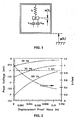
- FIG. 1 is a schematic diagram illustrating a damped mass-spring model representative of an exemplary embodiment of the geophone of this invention. Both electrical and mechanical damping may be considered in analyzing and optimizing the design for particular ambient vibration spectra.
- a mass m, a spring constant k, an electrical damping factor be, a mechanical damping factor b m , and a displacement function z(t) the power P available from the coil current may be expressed as shown in Eqn.
- FIG. 2 is a chart illustrating the expected coil voltage, flux density and relative displacement for various electrical and mechanical assumptions.
- the peak coil voltage shown in FIG. 2 refers to the voltage per coil winding.
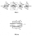
- FIGS. 3a-3d show an illustrative edge view of several different coil/flux configurations.
- coil 20 is disposed at flux gap 22 formed by the two magnetic masses 24 and 26.
- a "steep" flux gradient region is formed in flux gap 22 by virtue of the similar magnetic poles facing or aligned with each other on each edge of flux gap 22.
- FIGS. 3c and 3d a "shallow" flux gradient region is formed in flux gap 22 by virtue of the dissimilar magnetic poles on each edge of flux gap 22.
- coil 20 is disposed in flux gap 22 such that any vertical motion Z(t) of mass 26 with respect to mass 24 and coil 20 produces a rapid change in magnetic flux at coil 20.
- coil 20 is disposed in flux gap 22 such that any synchronous vertical motion Z(t) of both masses 24 and 26 together with respect to coil 20 produces a rapid change in magnetic flux at coil 20.
- FIG. 3a coil 20 is disposed in flux gap 22 such that any synchronous vertical motion Z(t) of both masses 24 and 26 together with respect to coil 20 produces a rapid change in magnetic flux at coil 20.
- 3c coil 20 is disposed in flux gap 22 such that any vertical motion Z(t) of mass 26 with respect to mass 24 and coil 20 produces a limited change in magnetic flux at coil 20.
- coil 20 is disposed in flux gap 22 such that any synchronous horizontal motion Y(t) of both masses 24 and 26 together with respect to coil 20 produces a limited change in magnetic flux at coil 20.
- additional magnetic masses may also be added to any of the configurations shown in FIGS. 3a-3d and the depicted masses reorganized to form other useful geometric configurations as alternative embodiments of the geophone of the present invention.
- six or more magnetic masses may be used to further increase the magnetic field gradient.
- Groups of the magnetic masses may be configured to detect movement in substantially perpendicular directions.
- two (or more) of the magnetic masses may be configured to detect movement along the X axis
- two (or more) other masses may be configured to detect movement along the Y axis
- two (or more) other masses may be configured to detect movement along the Z axis.
- More than six magnetic masses may be used in other embodiments.
- Each group of two or more magnetic masses may be arranged so that similar magnetic poles are aligned or facing each other.
- the magnetic masses may be positioned in any suitable geometric configuration.
- FIG. 4a is an exemplary illustration of flux gap 36 created between and surrounding magnetic masses 42 and 44.
- Flux gap 36 may be created when magnetic inner surfaces of masses 42 and 44 have the same polarity.
- Flux gap 36 may be the region between and surrounding the physical midpoint 50 of magnetic mass 42 and physical midpoint 52 of magnetic mass 44.
- FIG. 4b is a diagram illustrating an edge perspective of an exemplary embodiment of the geophone of the present invention.
- Geophone 28 includes coil 30 consisting of a plurality of turns of electrically-conductive material coupled to coil terminals 32 and 34.
- Coil 30 may be coupled to a substrate material (not shown) and/or one or more compliant elements 46 and 48 (e.g., springs).
- Coil 30 is disposed in the flux gap 36 bounded by the inner surfaces 38 and 40 of the magnetic masses 42 and 44, respectively.
- the flux gap 36 may be the region between and surrounding the physical midpoint of magnetic mass:42 to the physical midpoint of magnetic mass 44, as shown in FIG. 4a .
- coil 30 may be dispersed in close proximity to the flux gap or surrounding magnetic masses 42 and 44.
- Inner surfaces 38 and 40 are shown as the N-poles of magnetic masses 42 and 44 but may be either polarity provided that both inner surfaces 38 and 40 have the same magnetic polarity.
- Magnetic mass 42 may be supported by one or more compliant elements (e.g., springs) exemplified by compliant element 46.
- magnetic mass 44 may be supported by one or more compliant elements exemplified by compliant element 48.
- the free ends of compliant elements 46 and 48 may be fixed to the substrate material (not shown) in any useful manner, thereby allowing magnetic masses 42 and 44 to move in the Z(t) direction with respect to coil 30 in response to seismic vibration or external mechanical vibration.
- Magnetic masses 42 and 44 may be rigidly coupled to one another and disposed to move synchronously in response to seismic vibration or external mechanical vibration. Additional magnetic masses may also be included in geophone 28 that are configured to move in the Y(t) direction and in the X(t) direction with respect to coil 30.
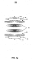
- FIG. 4a one coil 30 is shown in FIG. 4a for the sake of simplicity, other embodiments as shown in FIG. 4g may include plurality of coils 30 connected either in series or parallel.
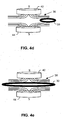
- FIGS. 4c , 4d and 4e illustrate an edge perspective of alternative embodiments of geophone 28 of the present invention.
- coil 30 may be disposed in the flux gap 36 outside of magnetic masses 42 and 44.
- coil 30 may be placed in flux gap 36 surrounding magnetic masses 42 and 44.
- FIGS. 4a-4e The compressed magnetic field gradient created by facing two (or more) like magnetic poles together as shown FIGS. 4a-4e allows for a greater voltage signal to be generated between terminals 32 and 34 ( FIG. 4b ) for a given vibration amount because coil 30 may experience a greater change in magnetic flux over a smaller distance.
- the exemplary configurations shown in FIGS. 4b-4e may result in a greater voltage signal without increasing the noise or geophone size, thus advantageously resulting in a greater signal-to-noise ratio than in a conventional geophone configuration.
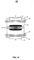
- FIG. 4f illustrates an exemplary embodiment of geophone 28 in which coil 30 is connected to compliant regions 46 and 48. Additionally, as shown in FIG. 4f , in some embodiments, inertial mass 54 may be attached to outer edges of coil 30 to provide a mechanical damping force.
- FIGS. 4b-4g show coil 30 disposed within the flux gap between magnetic masses 42 and 44
- coil 30 may also be disposed surrounding magnetic masses 42 and 44.
- coil 30 may be extended around the outside of magnetic masses 42 and 44 and up to the physical midpoints 50 and 52 of magnetic masses 42 and 44.
- FIG. 5 illustrates an exemplary system utilizing an exemplary embodiment of the geophone of the present invention.
- geophone 28 may be utilized as a vibration measuring apparatus operably connected to output device 50.
- Terminals 32 and 34 of coil 30 of vibration measuring apparatus 28 may be operably connected to output device 50.
- Output device 50 may include a display unit (not shown) and/or a speaker unit (not shown) to provide a visual and/or audible indication of the vibrations measured by vibration measuring apparatus 28.
- output device 50 takes the form of a voltmeter or other device capable of detecting or measuring the potential difference across terminals 32 and 34 of coil 30.
- Output device 50 may also include memory (e.g., RAM, ROM, and hybrid types of memory) and storage (e.g., optical, tape, or hard disk drives) coupled to processing circuitry (not shown), as well as at least one analog-to digital converter (ADC) for converting the received voltage signal to a digital signal for processing.
- memory e.g., RAM, ROM, and hybrid types of memory
- storage e.g., optical, tape, or hard disk drives
- ADC analog-to digital converter
- output device 50 may include a computer and/or seismic imaging equipment.
- the computer or seismic imaging equipment may be configured to record a log of recorded vibration measurements performed continuously, periodically, or on a user-defined schedule. The log may then be saved to volatile or non-volatile memory or recorded to a local or network storage device (not shown).
- Output device 50 may also include an integrated network controller (e.g., wireless network controller) for saving vibration measurements to a remote storage device or network, such as the Internet or a secured virtual private network (VPN) or intranet.
- the system of FIG. 5 may be implemented in various applications, such as machine monitoring, seismic imaging, etc.
Landscapes
- Engineering & Computer Science (AREA)
- Remote Sensing (AREA)
- Physics & Mathematics (AREA)
- Life Sciences & Earth Sciences (AREA)
- Acoustics & Sound (AREA)
- Environmental & Geological Engineering (AREA)
- Geology (AREA)
- General Life Sciences & Earth Sciences (AREA)
- General Physics & Mathematics (AREA)
- Geophysics (AREA)
- Measurement Of Mechanical Vibrations Or Ultrasonic Waves (AREA)
- Geophysics And Detection Of Objects (AREA)
Description
- This invention relates generally to geophones, and more particularly to a high-sensitivity geophone with an improved signal-to-noise ratio.
- A geophone is an instrument used to transform seismic energy or vibrations into a voltage signal. A conventional geophone includes a single coil and a ferromagnetic mass (e.g., a magnet), both of which may be contained in a housing. Springs may support the coil, thus allowing motion in one dimension relative to the housing. The magnet may be fixed with respect to the housing and, as the geophone is vibrated, the coil may move relative to the magnet. The relative motion of the coil may induce an electromotive force, or voltage, in the coil. A "single-coil" may include a single, continuous length of wire has been wound into a coil, and that connection to the coil is available at the two ends, or terminals, of the wire. The voltage across these two terminals may provide the output signal from the device. This voltage may be proportional to the velocity of the housing for frequencies above the natural resonant frequency of the spring-coil-mass system. Such a geophone is known from
US 3593258 . - One of the drawbacks encountered with the above-referenced design is the inability to increase the sensitivity of the geophone without dramatically increasing the size of the geophone (e.g., the length of the coil and/or the size of the ferromagnetic masses). Increasing the size of the geophone generally leads to decreased portability and increased operating costs. Therefore, it would be desirable to provide a more sensitive geophone with a higher signal-to-noise ratio.
- In accordance with an exemplary embodiment of the present invention, systems and methods for measuring vibration using a geophone are provided. The geophone configuration includes a substrate with one or more integral compliant regions (e.g., springs), at least two ferromagnetic masses (e.g., magnets) positioned with like magnetic poles facing each other so as to compress the magnetic field gradient, and a coil. One or more of the ferromagnetic masses may be coupled to a corresponding one or more of the integral compliant regions such that at least one of the ferromagnetic masses moves with respect to the substrate responsive to substrate acceleration. The facing or aligned inner magnetic poles of at least two of the ferromagnetic masses may form a steep magnetic flux gradient region in and around the flux gap. The coil may be coupled to the substrate and disposed within the steep flux gradient region where it is exposed to a changing magnetic flux arising from motion of at least one of the ferromagnetic masses with respect to the substrate. In various exemplary embodiments, the coil may be positioned in the flux gap either between the magnets, in close proximity to the magnets, or surrounding the magnets.
- The compressed magnetic field gradient created by facing at least two like magnetic poles together may allow for a greater voltage signal to be generated between the two terminals of the coil for a given vibration amount because the coil may experience a greater change in magnetic flux over a shorter distance. This configuration may result in a greater voltage signal without increasing the noise, thus advantageously resulting in a greater signal-to-noise ratio than a conventional geophone configuration.
- In some embodiments, the geophone configuration of the present invention may be used for vibration measurements, including machine monitoring, seismic imaging, and other applications requiring vibration measurements. The coil terminals may be connected to one or more output devices configured to provide a visual, audible, or recorded output indicative of the measured vibration.
- In an alternate embodiment of the geophone described above, at least two of the ferromagnetic masses may be rigidly coupled to one another and disposed to move synchronously.
- In another alternate embodiment of the geophone described above, two or more of the coupled ferromagnetic masses may be configured to move linearly with respect to the substrate responsive to substrate acceleration.
- In another alternate embodiment of the geophone described above, conductors may be coupled to the coil for conducting electrical current flowing in response to the changing magnetic flux.
- In another alternate embodiment of the geophone described above, the single coil may be replaced with a plurality of independent coils coupled to the substrate and disposed within the steep flux gradient region where the plurality of independent coils are exposed to the changing magnetic flux. The coils may be connected in series or parallel.
- In another alternate embodiment of the geophone described above, the coil may be disposed within the steep flux gradient region within the flux gap.
- In another alternate embodiment of the geophone described above, the coil may be disposed within the steep flux gradient region outside or near the flux gap.
- The above and other objects and advantages of the invention will be apparent upon consideration of the following detailed description, taken in conjunction with the accompanying drawings, in which like reference characters refer to like parts throughout, and in which:
-
FIG. 1 is a schematic diagram illustrating a damped mass-spring model representative of an exemplary embodiment of the geophone of the present invention; -
FIG. 2 is a chart illustrating the theoretical relationship between coil voltage, flux density and relative displacement according to classical electromagnetic theory for the model ofFIG. 1 ; -
FIGS. 3a-3d illustrate an edge view of several different coil/flux configurations in accordance with various exemplary embodiments of the geophone of the present invention; -
FIG. 4a illustrates the flux gap created between and surrounding two magnetic masses; -
FIGS. 4b-4h illustrate an edge perspective of various exemplary embodiments of the geophone of the present invention; and -
FIG. 5 illustrates an exemplary system utilizing an exemplary embodiment of the geophone of the present invention. -
FIG. 1 is a schematic diagram illustrating a damped mass-spring model representative of an exemplary embodiment of the geophone of this invention. Both electrical and mechanical damping may be considered in analyzing and optimizing the design for particular ambient vibration spectra. Referring toFIG. 1 , for time t, a mass m, a spring constant k, an electrical damping factor be, a mechanical damping factor bm, and a displacement function z(t), the power P available from the coil current may be expressed as shown in Eqn. 1:
- Conservation of energy leads to Eqn. 2:

- Laplacian transformation and the substitution of variables can be shown to provide the following Eqns. 3-7:


- This is a non-linear problem and, because of the nonlinear nature of the reaction force from the coil current, the system resonance may be optimized with reference to Eqn. 7 for a given application. In general, a higher electrical damping be may improve power output performance at frequencies below the mechanical resonant frequency fr = 2Πωn of the system.
-
FIG. 2 is a chart illustrating the expected coil voltage, flux density and relative displacement for various electrical and mechanical assumptions. The acceleration is assumed to be a constant 1.0 m/sec2 over the entire frequency range, Bmax = 1 Tesla, k = 1 N/m, velocity = 50 mm/sec, mass = 1 mg, and x = 1 mm. The peak coil voltage shown inFIG. 2 refers to the voltage per coil winding. -
FIGS. 3a-3d show an illustrative edge view of several different coil/flux configurations. InFIG. 3 ,coil 20 is disposed atflux gap 22 formed by the twomagnetic masses FIGS. 3a and 3b , a "steep" flux gradient region is formed influx gap 22 by virtue of the similar magnetic poles facing or aligned with each other on each edge offlux gap 22. - In
FIGS. 3c and 3d , a "shallow" flux gradient region is formed influx gap 22 by virtue of the dissimilar magnetic poles on each edge offlux gap 22. InFIG. 3a ,coil 20 is disposed influx gap 22 such that any vertical motion Z(t) ofmass 26 with respect tomass 24 andcoil 20 produces a rapid change in magnetic flux atcoil 20. Similarly, inFIG. 3(b) coil 20 is disposed influx gap 22 such that any synchronous vertical motion Z(t) of bothmasses coil 20 produces a rapid change in magnetic flux atcoil 20. In contrast, inFIG. 3c coil 20 is disposed influx gap 22 such that any vertical motion Z(t) ofmass 26 with respect tomass 24 andcoil 20 produces a limited change in magnetic flux atcoil 20. Similarly, inFIG. 3d coil 20 is disposed influx gap 22 such that any synchronous horizontal motion Y(t) of bothmasses coil 20 produces a limited change in magnetic flux atcoil 20. Moreover, additional magnetic masses may also be added to any of the configurations shown inFIGS. 3a-3d and the depicted masses reorganized to form other useful geometric configurations as alternative embodiments of the geophone of the present invention. - For example, in some embodiments six or more magnetic masses may be used to further increase the magnetic field gradient. Groups of the magnetic masses may be configured to detect movement in substantially perpendicular directions. For example, two (or more) of the magnetic masses may be configured to detect movement along the X axis, two (or more) other masses may be configured to detect movement along the Y axis and two (or more) other masses may be configured to detect movement along the Z axis. More than six magnetic masses may be used in other embodiments. Each group of two or more magnetic masses may be arranged so that similar magnetic poles are aligned or facing each other. The magnetic masses may be positioned in any suitable geometric configuration.
-
FIG. 4a is an exemplary illustration offlux gap 36 created between and surroundingmagnetic masses Flux gap 36 may be created when magnetic inner surfaces ofmasses Flux gap 36 may be the region between and surrounding thephysical midpoint 50 ofmagnetic mass 42 andphysical midpoint 52 ofmagnetic mass 44. -
FIG. 4b is a diagram illustrating an edge perspective of an exemplary embodiment of the geophone of the present invention.Geophone 28 includescoil 30 consisting of a plurality of turns of electrically-conductive material coupled tocoil terminals Coil 30 may be coupled to a substrate material (not shown) and/or one or morecompliant elements 46 and 48 (e.g., springs).Coil 30 is disposed in theflux gap 36 bounded by theinner surfaces magnetic masses flux gap 36 may be the region between and surrounding the physical midpoint of magnetic mass:42 to the physical midpoint ofmagnetic mass 44, as shown inFIG. 4a . In other embodiments,coil 30 may be dispersed in close proximity to the flux gap or surroundingmagnetic masses
surfaces 38 and 40 are shown as the N-poles ofmagnetic masses inner surfaces -
Magnetic mass 42 may be supported by one or more compliant elements (e.g., springs) exemplified bycompliant element 46. Similarly,magnetic mass 44 may be supported by one or more compliant elements exemplified bycompliant element 48. The free ends ofcompliant elements magnetic masses coil 30 in response to seismic vibration or external mechanical vibration.Magnetic masses geophone 28 that are configured to move in the Y(t) direction and in the X(t) direction with respect tocoil 30. Although onecoil 30 is shown inFIG. 4a for the sake of simplicity, other embodiments as shown inFIG. 4g may include plurality ofcoils 30 connected either in series or parallel. -
FIGS. 4c ,4d and 4e illustrate an edge perspective of alternative embodiments ofgeophone 28 of the present invention. As shown inFIGS. 4c and4d ,coil 30 may be disposed in theflux gap 36 outside ofmagnetic masses FIG. 4e ,coil 30 may be placed influx gap 36 surroundingmagnetic masses - The compressed magnetic field gradient created by facing two (or more) like magnetic poles together as shown
FIGS. 4a-4e allows for a greater voltage signal to be generated betweenterminals 32 and 34 (FIG. 4b ) for a given vibration amount becausecoil 30 may experience a greater change in magnetic flux over a smaller distance. The exemplary configurations shown inFIGS. 4b-4e may result in a greater voltage signal without increasing the noise or geophone size, thus advantageously resulting in a greater signal-to-noise ratio than in a conventional geophone configuration. -
FIG. 4f illustrates an exemplary embodiment ofgeophone 28 in whichcoil 30 is connected tocompliant regions FIG. 4f , in some embodiments,inertial mass 54 may be attached to outer edges ofcoil 30 to provide a mechanical damping force. - Although the embodiments shown in
FIGS. 4b- 4g show coil 30 disposed within the flux gap betweenmagnetic masses coil 30 may also be disposed surroundingmagnetic masses FIG. 4h ,coil 30 may be extended around the outside ofmagnetic masses physical midpoints magnetic masses -
FIG. 5 illustrates an exemplary system utilizing an exemplary embodiment of the geophone of the present invention. As shown inFIG. 5 ,geophone 28 may be utilized as a vibration measuring apparatus operably connected tooutput device 50.Terminals coil 30 ofvibration measuring apparatus 28 may be operably connected tooutput device 50.Output device 50 may include a display unit (not shown) and/or a speaker unit (not shown) to provide a visual and/or audible indication of the vibrations measured byvibration measuring apparatus 28. For example, in someembodiments output device 50 takes the form of a voltmeter or other device capable of detecting or measuring the potential difference acrossterminals coil 30.Output device 50 may also include memory (e.g., RAM, ROM, and hybrid types of memory) and storage (e.g., optical, tape, or hard disk drives) coupled to processing circuitry (not shown), as well as at least one analog-to digital converter (ADC) for converting the received voltage signal to a digital signal for processing. - In some embodiments,
output device 50 may include a computer and/or seismic imaging equipment. The computer or seismic imaging equipment may be configured to record a log of recorded vibration measurements performed continuously, periodically, or on a user-defined schedule. The log may then be saved to volatile or non-volatile memory or recorded to a local or network storage device (not shown).Output device 50 may also include an integrated network controller (e.g., wireless network controller) for saving vibration measurements to a remote storage device or network, such as the Internet or a secured virtual private network (VPN) or intranet. The system ofFIG. 5 may be implemented in various applications, such as machine monitoring, seismic imaging, etc. - The above described embodiments of the present invention are presented for purposes of illustration and not of limitation, and the present invention is limited only by the claims which follow.
Claims (20)
- A system for measuring vibrations comprising:a vibration measuring apparatus; andan output device operably connected to the vibration measuring apparatus configured to generate an indication based at least in part on vibrations measured by said vibration measuring apparatus;said vibration measuring apparatus comprising:a substrate having one or more integral compliant regions;a plurality of ferromagnetic masses, each ferromagnetic mass coupled to corresponding one or more of the integral compliant regions wherein at least one of the ferromagnetic masses moves with respect to the substrate responsive to substrate acceleration, wherein at least two of the plurality of ferromagnetic masses have an inner magnetic pole disposed such that the inner magnetic poles are separated from one another by a flux gap, wherein the magnetic polarity of each inner magnetic pole is similar to the magnetic polarity of the inner magnetic pole on an opposite side of the flux gap; andone or more coils coupled to the substrate and disposed within the flux gap where the one or more coils are exposed to a changing magnetic flux arising from motion of at least one of the ferromagnetic masses with respect to the substrate, characterized in that the one or more coils are disposed within the flux gap between the at least two ferromagnetic masses.
- The system of claim 1, wherein the one or more coils are disposed in a region bounded by inner surfaces of the ferromagnetic masses.
- The system of claim 1, wherein the one or more coils are disposed within the flux gap outside of the at least two ferromagnetic masses.
- The system of claim 1, wherein the one or more coils are disposed within the flux gap surrounding the at least two ferromagnetic masses.
- The system of claim 1, wherein the one or more coils are connected to one or more of the integral compliant regions.
- The system of claim 1, wherein the at least two ferromagnetic masses are rigidly coupled to one another and disposed to move synchronously.
- The system of claim 1, wherein the one or more coils comprises at least two coils that are connected in series or parallel.
- The system of claim 5, further comprising an inertial mass that is attached to outer edges of the one or more coils.
- The system of claim 1, wherein the plurality of ferromagnetic masses comprises six ferromagnetic masses, wherein two ferromagnetic masses are configured to detect movement in a first direction, two ferromagnetic masses are configured to detect movement in a second direction substantially perpendicular to the first direction and two ferromagnetic masses are configured to detect movement in a third direction substantially perpendicular to the first direction and the second direction.
- A method for measuring vibrations comprising:disposing one or more coils within a flux gap created between a plurality of ferromagnetic masses, wherein at least two of the plurality of ferromagnetic masses have an inner magnetic pole separated from one another by the flux gap, and wherein the magnetic polarity of each inner magnetic pole is similar to the magnetic polarity of the inner magnetic pole on the opposite side of the flux gap;measuring voltage generated on the one or more coils in response to changing magnetic flux arising from motion of at least one of the ferromagnetic masses; andgenerating an indication of vibrations based at least in part on the measured voltage, characterized in that disposing the one or more coils comprises disposing the one or more coils within the flux gap between the at least two ferromagnetic masses.
- The method of claim 10, wherein disposing the one or more coils comprises disposing the one or more coils in a region bounded by inner surfaces of the ferromagnetic masses.
- The method of claim 10, wherein disposing the one or more coils comprises disposing the one or more coils within the flux gap outside of the at least two ferromagnetic masses.
- The method of claim 10, wherein disposing the one or more coils comprises disposing the one or more coils within the flux gap surrounding the at least two ferromagnetic masses.
- The method of claim 10, wherein the one or more coils are connected to one or more integral compliant regions.
- The method of claim 10, wherein the at least two ferromagnetic masses are rigidly coupled to one another and disposed to move synchronously.
- The method of claim 10, wherein the coils are connected in series or parallel.
- The method of claim 10, wherein the plurality of ferromagnetic masses comprises six ferromagnetic masses, wherein two ferromagnetic masses are configured to detect movement in a first direction, two ferromagnetic masses are configured to detect movement in a second direction substantially perpendicular to the first direction and two ferromagnetic masses are configured to detect movement in a third direction substantially perpendicular to the first direction and the second direction.
- The method of claim 10, wherein generating the indication of vibrations comprises outputting the indication.
- The method of claim 10, further comprising recording the indication to a log.
- The method of claim 19, wherein recording the indication comprises recording the indication on a user-defined schedule.
Applications Claiming Priority (2)
| Application Number | Priority Date | Filing Date | Title |
|---|---|---|---|
| US12/534,538 US8443673B2 (en) | 2009-08-03 | 2009-08-03 | High sensitivity geophone |
| PCT/US2010/042895 WO2011017014A2 (en) | 2009-08-03 | 2010-07-22 | High sensitivity geophone |
Publications (2)
| Publication Number | Publication Date |
|---|---|
| EP2462472A2 EP2462472A2 (en) | 2012-06-13 |
| EP2462472B1 true EP2462472B1 (en) | 2016-11-23 |
Family
ID=43525729
Family Applications (1)
| Application Number | Title | Priority Date | Filing Date |
|---|---|---|---|
| EP10740062.4A Not-in-force EP2462472B1 (en) | 2009-08-03 | 2010-07-22 | High sensitivity geophone |
Country Status (6)
| Country | Link |
|---|---|
| US (1) | US8443673B2 (en) |
| EP (1) | EP2462472B1 (en) |
| JP (1) | JP2013501240A (en) |
| AU (1) | AU2010281508B2 (en) |
| CA (1) | CA2769706C (en) |
| WO (1) | WO2011017014A2 (en) |
Families Citing this family (8)
| Publication number | Priority date | Publication date | Assignee | Title |
|---|---|---|---|---|
| US5852037A (en) * | 1995-11-13 | 1998-12-22 | Eli Lilly And Company | Method for treating anxiety |
| RU2473929C1 (en) * | 2011-09-29 | 2013-01-27 | Федеральное государственное унитарное предприятие "Всероссийский научно-исследовательский институт автоматики им. Н.Л. Духова" (ФГУП "ВНИИА") | Seismometer |
| RU2586703C1 (en) * | 2014-11-05 | 2016-06-10 | Федеральное государственное бюджетное учреждение науки Институт океанологии им. П.П. Ширшова, Российской академии наук | Method of generating standard tension of fibre-optic guide in geophone housing |
| US10156649B2 (en) | 2014-12-29 | 2018-12-18 | Halliburton Energy Services, Inc. | Dual core locking geophone |
| US10320275B2 (en) | 2015-11-13 | 2019-06-11 | Charles Brent Curry | Repelling electric generator |
| CN107014403A (en) * | 2017-04-13 | 2017-08-04 | 西安振兴泽博智能震感科技有限公司 | A kind of moving-coil sensor movement |
| JP6585217B2 (en) * | 2018-03-27 | 2019-10-02 | 辻野 次郎丸 | Compound bending vibration detection method |
| RU2717165C1 (en) * | 2019-06-13 | 2020-03-18 | Федеральное Государственное Унитарное Предприятие "Всероссийский Научно-Исследовательский Институт Автоматики Им.Н.Л.Духова" (Фгуп "Внииа") | Seismic sensor |
Family Cites Families (28)
| Publication number | Priority date | Publication date | Assignee | Title |
|---|---|---|---|---|
| US3251028A (en) * | 1963-08-08 | 1966-05-10 | Mandrel Industries | Geophone |
| US3412376A (en) * | 1967-05-10 | 1968-11-19 | Mark Products | Low-frequency seismometer |
| US3582874A (en) | 1969-03-12 | 1971-06-01 | Nikolai Efimovich Fedoseenko | Electrodynamic seismic receiver |
| US3593258A (en) * | 1969-08-15 | 1971-07-13 | Mandrel Industries | Dual magnetic circuit low leakage geophone |
| JPS4873680U (en) * | 1971-12-17 | 1973-09-13 | ||
| US3852874A (en) * | 1972-03-02 | 1974-12-10 | Smith Williston Inc | Method of inserting buttons in a drilling head |
| US3878504A (en) * | 1973-09-21 | 1975-04-15 | Hall Sears Inc | Damped geophone |
| JPS5491313A (en) * | 1977-12-28 | 1979-07-19 | Hitachi Metals Ltd | Equiipolarity opposite concentrical gap magnetic circuit |
| NL175856C (en) * | 1979-12-21 | 1987-12-16 | Terra Dynamics B V | TRANSMITTER FOR RECORDING MECHANICAL VIBRATIONS AND A SEIZE METER CONTAINED WITH SUCH A TRANSMITTER, IN ADDITION TO A SWITCH FOR SUB-GROUPING A NUMBER OF SUCH SEAMOMETERS. |
| JPH07113577B2 (en) * | 1985-01-16 | 1995-12-06 | フジテック株式会社 | Earthquake detector |
| US5193391A (en) * | 1990-11-14 | 1993-03-16 | Cage Donald R | Controlled vibration angular rate sensor |
| JP3098045B2 (en) * | 1990-12-13 | 2000-10-10 | シュルンベルジェ オーバーシーズ エス.エイ. | Electrodynamic accelerometer |
| JP2603920Y2 (en) * | 1993-03-10 | 2000-04-04 | フオスター電機株式会社 | Speaker |
| JP3137158B2 (en) * | 1993-12-09 | 2001-02-19 | 株式会社アカシ | Shock vibrometer attenuator |
| JP2000065853A (en) * | 1998-08-26 | 2000-03-03 | Tadatoshi Goto | Detection device of vibration or acceleration |
| JP2001033562A (en) * | 1999-07-15 | 2001-02-09 | Akashi Corp | Data logger and vibration measurement system |
| EP1099990B1 (en) * | 1999-11-12 | 2009-03-04 | Asulab S.A. | Generator for timepiece |
| GB2366474B (en) * | 2000-09-01 | 2005-02-16 | Schlumberger Ltd | Geophones |
| JP4653909B2 (en) * | 2001-07-31 | 2011-03-16 | 株式会社ミツトヨ | Electrodynamic detector |
| US6768230B2 (en) * | 2002-02-19 | 2004-07-27 | Rockwell Scientific Licensing, Llc | Multiple magnet transducer |
| GB2412501B (en) * | 2004-03-26 | 2007-10-31 | Univ Southampton | An electromagnetic device for converting mechanical vibrational energy into electrical energy |
| US7501726B1 (en) * | 2004-07-28 | 2009-03-10 | The United States Of America As Represented By The Secretary Of The Navy | Micro-electro-mechanical system (MEMS) and apparatus for generating power responsive to mechanical vibration |
| JP4049156B2 (en) * | 2005-02-17 | 2008-02-20 | 松下電器産業株式会社 | Vibration detector |
| US7688036B2 (en) * | 2006-06-26 | 2010-03-30 | Battelle Energy Alliance, Llc | System and method for storing energy |
| US7869001B2 (en) * | 2006-11-08 | 2011-01-11 | Asml Netherlands B.V. | Eddy current damper, and lithographic apparatus having an eddy current damper |
| GB2439411B (en) * | 2007-04-27 | 2008-07-23 | Perpetuum Ltd | An electromechanical generator for converting mechanical vibrational energy into electrical energy |
| GB2456313B (en) * | 2008-01-10 | 2010-05-12 | Westerngeco Seismic Holdings | Sensor devices |
| JP5846688B2 (en) | 2009-03-06 | 2016-01-20 | ルメダイン テクノロジーズ インコーポレイテッド | Device for generating electrical power in response to mechanical vibration |
-
2009
- 2009-08-03 US US12/534,538 patent/US8443673B2/en active Active
-
2010
- 2010-07-22 EP EP10740062.4A patent/EP2462472B1/en not_active Not-in-force
- 2010-07-22 JP JP2012523636A patent/JP2013501240A/en active Pending
- 2010-07-22 CA CA2769706A patent/CA2769706C/en not_active Expired - Fee Related
- 2010-07-22 AU AU2010281508A patent/AU2010281508B2/en not_active Ceased
- 2010-07-22 WO PCT/US2010/042895 patent/WO2011017014A2/en not_active Ceased
Also Published As
| Publication number | Publication date |
|---|---|
| US8443673B2 (en) | 2013-05-21 |
| AU2010281508A1 (en) | 2012-02-23 |
| AU2010281508B2 (en) | 2015-02-19 |
| CA2769706A1 (en) | 2011-02-10 |
| CA2769706C (en) | 2016-05-24 |
| WO2011017014A3 (en) | 2011-07-07 |
| JP2013501240A (en) | 2013-01-10 |
| WO2011017014A2 (en) | 2011-02-10 |
| EP2462472A2 (en) | 2012-06-13 |
| US20110023614A1 (en) | 2011-02-03 |
Similar Documents
| Publication | Publication Date | Title |
|---|---|---|
| CA2769706C (en) | High sensitivity geophone | |
| EP1314052B1 (en) | Geophone and method of manufacturing a geophone | |
| US9041230B2 (en) | Method and apparatus for motional/vibrational energy harvesting via electromagnetic induction using a magnet array | |
| US4412317A (en) | Transducer for picking up mechanical vibrations, in particular seismic waves, and a seismic measuring system including such a transducer | |
| Lainé et al. | A high-sensitivity MEMS-based accelerometer | |
| US8907506B2 (en) | Multimodal vibration harvester combining inductive and magnetostrictive mechanisms | |
| EP0434702B1 (en) | A geophone system | |
| US20140293752A1 (en) | Multi-coil multi-terminal closed-loop geophone accelerometer | |
| Bijak et al. | Magnetic flux density analysis of magnetic spring in energy harvester by hall-effect sensors and 2d magnetostatic fe model | |
| JP2013501240A5 (en) | ||
| US9238251B2 (en) | Dual-coil geophone accelerometer | |
| CN109995215B (en) | Piezoelectric and electromagnetic coupled vibration sensors | |
| EP2325673B1 (en) | Seismograph sensor | |
| CN207352182U (en) | Seismometer magnetic field structure and magneto-electric seismometer | |
| CN108919343B (en) | Rotary seismometer | |
| RU2030767C1 (en) | Seismograph | |
| JPH0627135A (en) | Dynamic-electricity type accelerometer | |
| Oliver et al. | Design, fabrication, and modeling of a four-bar electromagnetic vibration power generator | |
| CN209676103U (en) | An Adaptive Vertically Coupled Vibration Sensor | |
| CN106019362A (en) | Moving coil type low-frequency expanded geophone | |
| JP2017184444A (en) | Vibration generator | |
| RU2098844C1 (en) | Acceleration seismic receiver | |
| JP2005351793A (en) | Acceleration measuring instrument | |
| SU911406A1 (en) | Vertical seismic receiver | |
| JPH067167B2 (en) | Sonde for measuring underground artificial elastic waves |
Legal Events
| Date | Code | Title | Description |
|---|---|---|---|
| PUAI | Public reference made under article 153(3) epc to a published international application that has entered the european phase |
Free format text: ORIGINAL CODE: 0009012 |
|
| 17P | Request for examination filed |
Effective date: 20120217 |
|
| AK | Designated contracting states |
Kind code of ref document: A2 Designated state(s): AL AT BE BG CH CY CZ DE DK EE ES FI FR GB GR HR HU IE IS IT LI LT LU LV MC MK MT NL NO PL PT RO SE SI SK SM TR |
|
| DAX | Request for extension of the european patent (deleted) | ||
| GRAP | Despatch of communication of intention to grant a patent |
Free format text: ORIGINAL CODE: EPIDOSNIGR1 |
|
| INTG | Intention to grant announced |
Effective date: 20160613 |
|
| RIN1 | Information on inventor provided before grant (corrected) |
Inventor name: CHISUM, BRAD Inventor name: WATERS, RICHARD Inventor name: FRALICK, MARK |
|
| GRAS | Grant fee paid |
Free format text: ORIGINAL CODE: EPIDOSNIGR3 |
|
| GRAA | (expected) grant |
Free format text: ORIGINAL CODE: 0009210 |
|
| AK | Designated contracting states |
Kind code of ref document: B1 Designated state(s): AL AT BE BG CH CY CZ DE DK EE ES FI FR GB GR HR HU IE IS IT LI LT LU LV MC MK MT NL NO PL PT RO SE SI SK SM TR |
|
| REG | Reference to a national code |
Ref country code: GB Ref legal event code: FG4D |
|
| REG | Reference to a national code |
Ref country code: CH Ref legal event code: EP |
|
| REG | Reference to a national code |
Ref country code: IE Ref legal event code: FG4D |
|
| REG | Reference to a national code |
Ref country code: AT Ref legal event code: REF Ref document number: 848414 Country of ref document: AT Kind code of ref document: T Effective date: 20161215 |
|
| REG | Reference to a national code |
Ref country code: DE Ref legal event code: R096 Ref document number: 602010038240 Country of ref document: DE |
|
| PG25 | Lapsed in a contracting state [announced via postgrant information from national office to epo] |
Ref country code: LV Free format text: LAPSE BECAUSE OF FAILURE TO SUBMIT A TRANSLATION OF THE DESCRIPTION OR TO PAY THE FEE WITHIN THE PRESCRIBED TIME-LIMIT Effective date: 20161123 |
|
| REG | Reference to a national code |
Ref country code: LT Ref legal event code: MG4D |
|
| REG | Reference to a national code |
Ref country code: NL Ref legal event code: MP Effective date: 20161123 |
|
| REG | Reference to a national code |
Ref country code: AT Ref legal event code: MK05 Ref document number: 848414 Country of ref document: AT Kind code of ref document: T Effective date: 20161123 |
|
| PG25 | Lapsed in a contracting state [announced via postgrant information from national office to epo] |
Ref country code: GR Free format text: LAPSE BECAUSE OF FAILURE TO SUBMIT A TRANSLATION OF THE DESCRIPTION OR TO PAY THE FEE WITHIN THE PRESCRIBED TIME-LIMIT Effective date: 20170224 Ref country code: SE Free format text: LAPSE BECAUSE OF FAILURE TO SUBMIT A TRANSLATION OF THE DESCRIPTION OR TO PAY THE FEE WITHIN THE PRESCRIBED TIME-LIMIT Effective date: 20161123 Ref country code: LT Free format text: LAPSE BECAUSE OF FAILURE TO SUBMIT A TRANSLATION OF THE DESCRIPTION OR TO PAY THE FEE WITHIN THE PRESCRIBED TIME-LIMIT Effective date: 20161123 Ref country code: NL Free format text: LAPSE BECAUSE OF FAILURE TO SUBMIT A TRANSLATION OF THE DESCRIPTION OR TO PAY THE FEE WITHIN THE PRESCRIBED TIME-LIMIT Effective date: 20161123 Ref country code: NO Free format text: LAPSE BECAUSE OF FAILURE TO SUBMIT A TRANSLATION OF THE DESCRIPTION OR TO PAY THE FEE WITHIN THE PRESCRIBED TIME-LIMIT Effective date: 20170223 |
|
| PG25 | Lapsed in a contracting state [announced via postgrant information from national office to epo] |
Ref country code: FI Free format text: LAPSE BECAUSE OF FAILURE TO SUBMIT A TRANSLATION OF THE DESCRIPTION OR TO PAY THE FEE WITHIN THE PRESCRIBED TIME-LIMIT Effective date: 20161123 Ref country code: PL Free format text: LAPSE BECAUSE OF FAILURE TO SUBMIT A TRANSLATION OF THE DESCRIPTION OR TO PAY THE FEE WITHIN THE PRESCRIBED TIME-LIMIT Effective date: 20161123 Ref country code: AT Free format text: LAPSE BECAUSE OF FAILURE TO SUBMIT A TRANSLATION OF THE DESCRIPTION OR TO PAY THE FEE WITHIN THE PRESCRIBED TIME-LIMIT Effective date: 20161123 Ref country code: PT Free format text: LAPSE BECAUSE OF FAILURE TO SUBMIT A TRANSLATION OF THE DESCRIPTION OR TO PAY THE FEE WITHIN THE PRESCRIBED TIME-LIMIT Effective date: 20170323 Ref country code: HR Free format text: LAPSE BECAUSE OF FAILURE TO SUBMIT A TRANSLATION OF THE DESCRIPTION OR TO PAY THE FEE WITHIN THE PRESCRIBED TIME-LIMIT Effective date: 20161123 Ref country code: ES Free format text: LAPSE BECAUSE OF FAILURE TO SUBMIT A TRANSLATION OF THE DESCRIPTION OR TO PAY THE FEE WITHIN THE PRESCRIBED TIME-LIMIT Effective date: 20161123 |
|
| PG25 | Lapsed in a contracting state [announced via postgrant information from national office to epo] |
Ref country code: RO Free format text: LAPSE BECAUSE OF FAILURE TO SUBMIT A TRANSLATION OF THE DESCRIPTION OR TO PAY THE FEE WITHIN THE PRESCRIBED TIME-LIMIT Effective date: 20161123 Ref country code: CZ Free format text: LAPSE BECAUSE OF FAILURE TO SUBMIT A TRANSLATION OF THE DESCRIPTION OR TO PAY THE FEE WITHIN THE PRESCRIBED TIME-LIMIT Effective date: 20161123 Ref country code: DK Free format text: LAPSE BECAUSE OF FAILURE TO SUBMIT A TRANSLATION OF THE DESCRIPTION OR TO PAY THE FEE WITHIN THE PRESCRIBED TIME-LIMIT Effective date: 20161123 Ref country code: EE Free format text: LAPSE BECAUSE OF FAILURE TO SUBMIT A TRANSLATION OF THE DESCRIPTION OR TO PAY THE FEE WITHIN THE PRESCRIBED TIME-LIMIT Effective date: 20161123 Ref country code: SK Free format text: LAPSE BECAUSE OF FAILURE TO SUBMIT A TRANSLATION OF THE DESCRIPTION OR TO PAY THE FEE WITHIN THE PRESCRIBED TIME-LIMIT Effective date: 20161123 |
|
| REG | Reference to a national code |
Ref country code: DE Ref legal event code: R097 Ref document number: 602010038240 Country of ref document: DE |
|
| PG25 | Lapsed in a contracting state [announced via postgrant information from national office to epo] |
Ref country code: BG Free format text: LAPSE BECAUSE OF FAILURE TO SUBMIT A TRANSLATION OF THE DESCRIPTION OR TO PAY THE FEE WITHIN THE PRESCRIBED TIME-LIMIT Effective date: 20170223 Ref country code: SM Free format text: LAPSE BECAUSE OF FAILURE TO SUBMIT A TRANSLATION OF THE DESCRIPTION OR TO PAY THE FEE WITHIN THE PRESCRIBED TIME-LIMIT Effective date: 20161123 Ref country code: IT Free format text: LAPSE BECAUSE OF FAILURE TO SUBMIT A TRANSLATION OF THE DESCRIPTION OR TO PAY THE FEE WITHIN THE PRESCRIBED TIME-LIMIT Effective date: 20161123 Ref country code: BE Free format text: LAPSE BECAUSE OF FAILURE TO SUBMIT A TRANSLATION OF THE DESCRIPTION OR TO PAY THE FEE WITHIN THE PRESCRIBED TIME-LIMIT Effective date: 20161123 |
|
| PLBE | No opposition filed within time limit |
Free format text: ORIGINAL CODE: 0009261 |
|
| STAA | Information on the status of an ep patent application or granted ep patent |
Free format text: STATUS: NO OPPOSITION FILED WITHIN TIME LIMIT |
|
| 26N | No opposition filed |
Effective date: 20170824 |
|
| PG25 | Lapsed in a contracting state [announced via postgrant information from national office to epo] |
Ref country code: SI Free format text: LAPSE BECAUSE OF FAILURE TO SUBMIT A TRANSLATION OF THE DESCRIPTION OR TO PAY THE FEE WITHIN THE PRESCRIBED TIME-LIMIT Effective date: 20161123 |
|
| REG | Reference to a national code |
Ref country code: DE Ref legal event code: R119 Ref document number: 602010038240 Country of ref document: DE |
|
| REG | Reference to a national code |
Ref country code: CH Ref legal event code: PL |
|
| GBPC | Gb: european patent ceased through non-payment of renewal fee |
Effective date: 20170722 |
|
| REG | Reference to a national code |
Ref country code: IE Ref legal event code: MM4A |
|
| REG | Reference to a national code |
Ref country code: FR Ref legal event code: ST Effective date: 20180330 |
|
| PG25 | Lapsed in a contracting state [announced via postgrant information from national office to epo] |
Ref country code: GB Free format text: LAPSE BECAUSE OF NON-PAYMENT OF DUE FEES Effective date: 20170722 Ref country code: LI Free format text: LAPSE BECAUSE OF NON-PAYMENT OF DUE FEES Effective date: 20170731 Ref country code: DE Free format text: LAPSE BECAUSE OF NON-PAYMENT OF DUE FEES Effective date: 20180201 Ref country code: CH Free format text: LAPSE BECAUSE OF NON-PAYMENT OF DUE FEES Effective date: 20170731 Ref country code: IE Free format text: LAPSE BECAUSE OF NON-PAYMENT OF DUE FEES Effective date: 20170722 |
|
| PG25 | Lapsed in a contracting state [announced via postgrant information from national office to epo] |
Ref country code: FR Free format text: LAPSE BECAUSE OF NON-PAYMENT OF DUE FEES Effective date: 20170731 |
|
| PG25 | Lapsed in a contracting state [announced via postgrant information from national office to epo] |
Ref country code: LU Free format text: LAPSE BECAUSE OF NON-PAYMENT OF DUE FEES Effective date: 20170722 |
|
| PG25 | Lapsed in a contracting state [announced via postgrant information from national office to epo] |
Ref country code: MT Free format text: LAPSE BECAUSE OF NON-PAYMENT OF DUE FEES Effective date: 20170722 |
|
| PG25 | Lapsed in a contracting state [announced via postgrant information from national office to epo] |
Ref country code: HU Free format text: LAPSE BECAUSE OF FAILURE TO SUBMIT A TRANSLATION OF THE DESCRIPTION OR TO PAY THE FEE WITHIN THE PRESCRIBED TIME-LIMIT; INVALID AB INITIO Effective date: 20100722 Ref country code: MC Free format text: LAPSE BECAUSE OF FAILURE TO SUBMIT A TRANSLATION OF THE DESCRIPTION OR TO PAY THE FEE WITHIN THE PRESCRIBED TIME-LIMIT Effective date: 20161123 |
|
| PG25 | Lapsed in a contracting state [announced via postgrant information from national office to epo] |
Ref country code: CY Free format text: LAPSE BECAUSE OF NON-PAYMENT OF DUE FEES Effective date: 20161123 |
|
| PG25 | Lapsed in a contracting state [announced via postgrant information from national office to epo] |
Ref country code: MK Free format text: LAPSE BECAUSE OF FAILURE TO SUBMIT A TRANSLATION OF THE DESCRIPTION OR TO PAY THE FEE WITHIN THE PRESCRIBED TIME-LIMIT Effective date: 20161123 |
|
| PG25 | Lapsed in a contracting state [announced via postgrant information from national office to epo] |
Ref country code: TR Free format text: LAPSE BECAUSE OF FAILURE TO SUBMIT A TRANSLATION OF THE DESCRIPTION OR TO PAY THE FEE WITHIN THE PRESCRIBED TIME-LIMIT Effective date: 20161123 |
|
| PG25 | Lapsed in a contracting state [announced via postgrant information from national office to epo] |
Ref country code: AL Free format text: LAPSE BECAUSE OF FAILURE TO SUBMIT A TRANSLATION OF THE DESCRIPTION OR TO PAY THE FEE WITHIN THE PRESCRIBED TIME-LIMIT Effective date: 20161123 Ref country code: IS Free format text: LAPSE BECAUSE OF FAILURE TO SUBMIT A TRANSLATION OF THE DESCRIPTION OR TO PAY THE FEE WITHIN THE PRESCRIBED TIME-LIMIT Effective date: 20170323 |
|
| P01 | Opt-out of the competence of the unified patent court (upc) registered |
Effective date: 20230520 |