EP2461454A2 - Integration of renewable power generating technologies with integrated volt/var control systems - Google Patents
Integration of renewable power generating technologies with integrated volt/var control systems Download PDFInfo
- Publication number
- EP2461454A2 EP2461454A2 EP20110188753 EP11188753A EP2461454A2 EP 2461454 A2 EP2461454 A2 EP 2461454A2 EP 20110188753 EP20110188753 EP 20110188753 EP 11188753 A EP11188753 A EP 11188753A EP 2461454 A2 EP2461454 A2 EP 2461454A2
- Authority
- EP
- European Patent Office
- Prior art keywords
- distribution system
- ivvc
- power
- energy source
- var
- Prior art date
- Legal status (The legal status is an assumption and is not a legal conclusion. Google has not performed a legal analysis and makes no representation as to the accuracy of the status listed.)
- Withdrawn
Links
Images

Classifications
-
- H—ELECTRICITY
- H02—GENERATION; CONVERSION OR DISTRIBUTION OF ELECTRIC POWER
- H02J—ELECTRIC POWER NETWORKS; CIRCUIT ARRANGEMENTS OR SYSTEMS FOR SUPPLYING OR DISTRIBUTING ELECTRIC POWER; SYSTEMS FOR STORING ELECTRIC ENERGY
- H02J3/00—Circuit arrangements for AC mains or AC distribution networks
- H02J3/18—Arrangements for adjusting, eliminating or compensating reactive power in networks
- H02J3/1821—Arrangements for adjusting, eliminating or compensating reactive power in networks using shunt compensators
- H02J3/1828—Arrangements for adjusting, eliminating or compensating reactive power in networks using shunt compensators with stepwise control, e.g. switched capacitor banks
-
- H—ELECTRICITY
- H02—GENERATION; CONVERSION OR DISTRIBUTION OF ELECTRIC POWER
- H02J—ELECTRIC POWER NETWORKS; CIRCUIT ARRANGEMENTS OR SYSTEMS FOR SUPPLYING OR DISTRIBUTING ELECTRIC POWER; SYSTEMS FOR STORING ELECTRIC ENERGY
- H02J3/00—Circuit arrangements for AC mains or AC distribution networks
- H02J3/38—Arrangements for feeding a single network from two or more generators or sources in parallel; Arrangements for feeding already energised networks from additional generators or sources in parallel
- H02J3/381—Dispersed generators
-
- H—ELECTRICITY
- H02—GENERATION; CONVERSION OR DISTRIBUTION OF ELECTRIC POWER
- H02J—ELECTRIC POWER NETWORKS; CIRCUIT ARRANGEMENTS OR SYSTEMS FOR SUPPLYING OR DISTRIBUTING ELECTRIC POWER; SYSTEMS FOR STORING ELECTRIC ENERGY
- H02J3/00—Circuit arrangements for AC mains or AC distribution networks
- H02J3/38—Arrangements for feeding a single network from two or more generators or sources in parallel; Arrangements for feeding already energised networks from additional generators or sources in parallel
- H02J3/46—Controlling the sharing of generated power between the generators, sources or networks
- H02J3/50—Controlling the sharing of reactive power
-
- H—ELECTRICITY
- H02—GENERATION; CONVERSION OR DISTRIBUTION OF ELECTRIC POWER
- H02J—ELECTRIC POWER NETWORKS; CIRCUIT ARRANGEMENTS OR SYSTEMS FOR SUPPLYING OR DISTRIBUTING ELECTRIC POWER; SYSTEMS FOR STORING ELECTRIC ENERGY
- H02J2101/00—Supply or distribution of decentralised, dispersed or local electric power generation
- H02J2101/20—Dispersed power generation using renewable energy sources
- H02J2101/22—Solar energy
- H02J2101/24—Photovoltaics
-
- H—ELECTRICITY
- H02—GENERATION; CONVERSION OR DISTRIBUTION OF ELECTRIC POWER
- H02J—ELECTRIC POWER NETWORKS; CIRCUIT ARRANGEMENTS OR SYSTEMS FOR SUPPLYING OR DISTRIBUTING ELECTRIC POWER; SYSTEMS FOR STORING ELECTRIC ENERGY
- H02J2101/00—Supply or distribution of decentralised, dispersed or local electric power generation
- H02J2101/20—Dispersed power generation using renewable energy sources
- H02J2101/28—Wind energy
-
- H—ELECTRICITY
- H02—GENERATION; CONVERSION OR DISTRIBUTION OF ELECTRIC POWER
- H02J—ELECTRIC POWER NETWORKS; CIRCUIT ARRANGEMENTS OR SYSTEMS FOR SUPPLYING OR DISTRIBUTING ELECTRIC POWER; SYSTEMS FOR STORING ELECTRIC ENERGY
- H02J2101/00—Supply or distribution of decentralised, dispersed or local electric power generation
- H02J2101/20—Dispersed power generation using renewable energy sources
- H02J2101/30—Fuel cells
-
- Y—GENERAL TAGGING OF NEW TECHNOLOGICAL DEVELOPMENTS; GENERAL TAGGING OF CROSS-SECTIONAL TECHNOLOGIES SPANNING OVER SEVERAL SECTIONS OF THE IPC; TECHNICAL SUBJECTS COVERED BY FORMER USPC CROSS-REFERENCE ART COLLECTIONS [XRACs] AND DIGESTS
- Y02—TECHNOLOGIES OR APPLICATIONS FOR MITIGATION OR ADAPTATION AGAINST CLIMATE CHANGE
- Y02E—REDUCTION OF GREENHOUSE GAS [GHG] EMISSIONS, RELATED TO ENERGY GENERATION, TRANSMISSION OR DISTRIBUTION
- Y02E10/00—Energy generation through renewable energy sources
- Y02E10/50—Photovoltaic [PV] energy
- Y02E10/56—Power conversion systems, e.g. maximum power point trackers
-
- Y—GENERAL TAGGING OF NEW TECHNOLOGICAL DEVELOPMENTS; GENERAL TAGGING OF CROSS-SECTIONAL TECHNOLOGIES SPANNING OVER SEVERAL SECTIONS OF THE IPC; TECHNICAL SUBJECTS COVERED BY FORMER USPC CROSS-REFERENCE ART COLLECTIONS [XRACs] AND DIGESTS
- Y02—TECHNOLOGIES OR APPLICATIONS FOR MITIGATION OR ADAPTATION AGAINST CLIMATE CHANGE
- Y02E—REDUCTION OF GREENHOUSE GAS [GHG] EMISSIONS, RELATED TO ENERGY GENERATION, TRANSMISSION OR DISTRIBUTION
- Y02E10/00—Energy generation through renewable energy sources
- Y02E10/70—Wind energy
- Y02E10/76—Power conversion electric or electronic aspects
-
- Y—GENERAL TAGGING OF NEW TECHNOLOGICAL DEVELOPMENTS; GENERAL TAGGING OF CROSS-SECTIONAL TECHNOLOGIES SPANNING OVER SEVERAL SECTIONS OF THE IPC; TECHNICAL SUBJECTS COVERED BY FORMER USPC CROSS-REFERENCE ART COLLECTIONS [XRACs] AND DIGESTS
- Y02—TECHNOLOGIES OR APPLICATIONS FOR MITIGATION OR ADAPTATION AGAINST CLIMATE CHANGE
- Y02E—REDUCTION OF GREENHOUSE GAS [GHG] EMISSIONS, RELATED TO ENERGY GENERATION, TRANSMISSION OR DISTRIBUTION
- Y02E40/00—Technologies for an efficient electrical power generation, transmission or distribution
- Y02E40/30—Reactive power compensation
Definitions
- the invention relates generally to integrated volt/var control systems, and more particularly to a system and method of integrating renewable power generating technologies with integrated volt/var control systems.
- VARs reactive power
- Watts real power
- VAR voltage regulation devices
- VAR On Load Tap Changer ⁇ OLTC, or voltage regulator - VR
- a number of different grid standards require utilities to provide their feeder terminal voltages, seen by end users, within a narrow range around the nominal value.
- the control of these mentioned Volt/VAR devices is implemented locally and individually at each device.
- an advanced control system is employed to coordinate between OLTC, VR, and capacitor bank control to achieve multiple customizable objective functions such as minimization of feeder loss, maximization of power factor at substation, minimization of total power demand during peak time, flattening voltage profile, and etc.
- This so-called integrated volt/var control (IVVC) employs advanced algorithms (e.g., global optimization algorithm, distribution load flow, distribution state estimation, distribution load forecasting) within a Distribution Management System (DMS) to accomplish this task.
- DMS Distribution Management System
- a power distribution system comprises: at least one renewable energy source or storage device; and a distribution management system (DMS) comprising an integrated volt/var controller (IVVC), wherein the DMS is configured to control operation of at least one corresponding renewable energy source or storage device power converter in response to IVVC commands such that at least one renewable energy source or storage device operates alone or in coordination with one or more discrete step size reactive power (VAR) compensation devices to generate continuously varying reactive power.
- DMS distribution management system
- IVVC integrated volt/var controller
- a power distribution system comprises: at least one renewable energy source or storage device configured in combination with one or more power converters to generate continuously varying amounts of reactive power; at least one reactive power (VAR) compensation device configured to provide predetermined incremental amounts of reactive power; an integrated volt/var controller (IVVC) comprising optimization algorithmic software; and a distribution management system (DMS) configured to control operation of the one or more renewable energy source or storage device power converters and the at least one VAR compensation device in response to the IVVC optimization algorithmic software such that at least one renewable energy source or storage device operates alone or in combination with at least one VAR compensation device to generate continuously varying reactive power required by the power distribution system.
- VAR reactive power
- IVVC integrated volt/var controller
- DMS distribution management system
- a method of operating a power distribution system comprises: providing at least one renewable energy source or energy storage device configured in combination with one or more power converters to generate continuously varying amounts of reactive power; providing at least one reactive power (VAR) compensation device configured to provide predetermined incremental amounts of reactive power; providing an integrated volt/var controller (IVVC) responsive to optimization algorithmic software; providing a distribution management system (DMS); and controlling operation of at least one corresponding renewable energy source or energy storage device power converter in response to IVVC commands determined via the optimization algorithmic software such that at least one renewable energy source or energy storage device operates to vary reactive power supplied to the power distribution system only when the one or more VAR compensation devices are capable of providing only less than or more than the reactive power required by the power distribution system.
- VAR reactive power
- IVVC integrated volt/var controller
- FIG. 1 illustrates a power distribution system 10 comprising a conventional distribution management system (DMS) 12.
- the DMS 12 operates in response to an integrated volt/var control (IVVC) system 14 comprising an algorithmic optimization software.
- IVVC integrated volt/var control
- VAR reactive power
- Distribution systems are also equipped with voltage regulation devices i.e., OLTC - on-load tap changers 24, or voltage (Volt) regulators 26, to more accurately control the voltage profile along feeders.
- voltage regulation devices i.e., OLTC - on-load tap changers 24, or voltage (Volt) regulators 26, to more accurately control the voltage profile along feeders.
- end users will always have incoming voltage levels within a specified range, e.g., Ipu +/- 5%.
- VAR compensation and Volt regulation devices until recently, were controlled based on local measurements. Such localized control techniques can disadvantageously result in fighting over master/slave control resulting in unnecessary on/off switching and reduced overall system performance. Coordinating the operation of all VAR compensation and Volt regulation devices from a central controller (DMS) 12 such as depicted in Figure 1 that may reside at the corresponding substation 18 or a DMS control room provides a global optimal solution to achieve minimization of transfer losses, flattening of voltage profiles, minimization of total power consumption, and the like.
- DMS central controller
- the present inventors recognized that with the emergence of distributed renewable energy generation/storage devices (e.g., PV, wind, battery storage, plug-in hybrid electric vehicle (PHEV)), interfacing a power grid via front-end power electronics renders a variety of possibilities for utilizing these free sources of reactive power to partially, or even totally, replace the traditional VAR compensation devices (i.e., capacitor banks 22). Unlike capacitor banks that can only provide bulk reactive power with discrete step sizes, front-end power electronics based devices can generate continuously varying reactive power, thus allowing for even more accurate VAR compensation. This technique further allows for changing power without requiring any hard switching, thus eliminating undesirable switching transients.
- distributed renewable energy generation/storage devices e.g., PV, wind, battery storage, plug-in hybrid electric vehicle (PHEV)
- PHEV plug-in hybrid electric vehicle
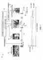
- Power distribution system 50 comprises an advanced DMS system 52 that operates in response to instructions provided via IVVC system 54 algorithmic software that together are configured to control VAR losses and maintain voltage levels using techniques such as described herein.
- Power distribution system 50 can be seen to comprise photovoltaic (PV) energy sources 56 and wind energy sources 58.
- PV photovoltaic
- PHEVs plug-in hybrid electric vehicles
- the power distribution system 50 is described with reference primarily to solar and wind energy sources to enhance clarity. Since solar and wind inverters have the ability to freely control their reactive output power, as stated herein, this feature can be employed via an optimization algorithm that generates IVVC system 54 commands 66 to add additional degrees of freedom for DMS system 52 VAR control. In this way, the freely controllable reactive power capabilities of corresponding solar/wind/fuel cell etc. inverters further enhance the capabilities of the IVVC system 54 optimization algorithmic software and corresponding DMS system 52.
- a distribution management system (DMS) 52 comprising integrated volt/var control (IVVC) system 54 software is configured to control operation of at least one corresponding renewable energy source or storage device power converter in response to the IVVC system 54 software such that at least one renewable energy source or storage device 56, 58, 60, 62, 64 operates alone or in coordination with one or more discrete step size reactive power (VAR) compensation devices 22 to generate continuously varying reactive power.
- VAR discrete step size reactive power
- This continuously varying reactive power can be transmitted to a corresponding power grid or feeder line 16 to provide the local reactive power required by an end user or load 20.
- the embodiments described herein incorporate not only traditional volt/var devices, e.g., voltage regulators, capacitor banks, but also renewable energy sources, e.g., wind/PV converters.
- the embodiments described herein apply system level control strategies to a power distribution system to regulate power flow on a network to achieve desired optimal objectives.
- reactive power control techniques have been applied to individual wind turbine controls at a lower lever, such known control techniques generally receive a set point command from the IVVC, and then operate the wind turbine to meet that request.
Landscapes
- Engineering & Computer Science (AREA)
- Power Engineering (AREA)
- Supply And Distribution Of Alternating Current (AREA)
- Charge And Discharge Circuits For Batteries Or The Like (AREA)
Abstract
A distribution management system (DMS) (12) includes an integrated volt/var controller (IVVC) (14) that is configured to control operation of at least one corresponding renewable energy source (56), (58) or energy storage device (60), (62), (64) power converter in response to IVVC commands generated via algorithmic optimization software integrated within the IVVC (14). At least one renewable energy source (56), (58) or energy storage device (60), (62), (64) is controlled to operate alone or in coordination with one or more discrete step size reactive power (VAR) compensation devices (22) to generate continuously varying reactive power required by a corresponding power distribution system (50).
Description
- The invention relates generally to integrated volt/var control systems, and more particularly to a system and method of integrating renewable power generating technologies with integrated volt/var control systems.
- Large inductive loads such as air conditioners, furnaces, dryers, and the like can consume reactive power (VARs) in addition to real power (Watts). Transferring reactive power over transmission lines and distribution feeders involves I2R losses that have to be supplied by utilities. Since residential power meters only measure Watts that are used to determine customer billing requirements, utilities want to minimize the number of VARs consumed. This result is generally achieved by switching in capacitor banks to compensate for VAR losses locally in distribution systems.
- Besides capacitor banks to provide VAR compensation, distribution systems are also equipped with voltage regulation devices (e.g., On Load Tap Changer ― OLTC, or voltage regulator - VR) to further increase the controllability of feeder voltages. A number of different grid standards require utilities to provide their feeder terminal voltages, seen by end users, within a narrow range around the nominal value. Traditionally, the control of these mentioned Volt/VAR devices is implemented locally and individually at each device. In recent years, an advanced control system is employed to coordinate between OLTC, VR, and capacitor bank control to achieve multiple customizable objective functions such as minimization of feeder loss, maximization of power factor at substation, minimization of total power demand during peak time, flattening voltage profile, and etc. This so-called integrated volt/var control (IVVC) employs advanced algorithms (e.g., global optimization algorithm, distribution load flow, distribution state estimation, distribution load forecasting) within a Distribution Management System (DMS) to accomplish this task.
- Bulk sized capacitor banks are switched either fully in or fully out according to IVVC command. Even for those multi-step capacitor banks, no matter how many steps they may have, the reactive power switched in or out will be in discrete set amounts that generally cannot be changed. In contrast, solar and wind inverters have the ability to freely control their reactive power output.
- In view of the foregoing, it would be advantageous to integrate freely controllable reactive power capabilities of renewable power generators including without limitation solar, wind, fuel cell, storage battery, and the like, with IVVC optimization algorithm(s) to provide an enhanced distribution management system.
- Briefly, in accordance with one embodiment of the present invention, a power distribution system comprises: at least one renewable energy source or storage device; and a distribution management system (DMS) comprising an integrated volt/var controller (IVVC), wherein the DMS is configured to control operation of at least one corresponding renewable energy source or storage device power converter in response to IVVC commands such that at least one renewable energy source or storage device operates alone or in coordination with one or more discrete step size reactive power (VAR) compensation devices to generate continuously varying reactive power.
- A power distribution system according to another embodiment comprises: at least one renewable energy source or storage device configured in combination with one or more power converters to generate continuously varying amounts of reactive power; at least one reactive power (VAR) compensation device configured to provide predetermined incremental amounts of reactive power; an integrated volt/var controller (IVVC) comprising optimization algorithmic software; and a distribution management system (DMS) configured to control operation of the one or more renewable energy source or storage device power converters and the at least one VAR compensation device in response to the IVVC optimization algorithmic software such that at least one renewable energy source or storage device operates alone or in combination with at least one VAR compensation device to generate continuously varying reactive power required by the power distribution system.
- According to yet another embodiment, a method of operating a power distribution system comprises: providing at least one renewable energy source or energy storage device configured in combination with one or more power converters to generate continuously varying amounts of reactive power; providing at least one reactive power (VAR) compensation device configured to provide predetermined incremental amounts of reactive power; providing an integrated volt/var controller (IVVC) responsive to optimization algorithmic software; providing a distribution management system (DMS); and controlling operation of at least one corresponding renewable energy source or energy storage device power converter in response to IVVC commands determined via the optimization algorithmic software such that at least one renewable energy source or energy storage device operates to vary reactive power supplied to the power distribution system only when the one or more VAR compensation devices are capable of providing only less than or more than the reactive power required by the power distribution system.
- Various features, aspects, and advantages of the present invention will become better understood when the following detailed description is read with reference to the accompanying drawings in which like characters represent like parts throughout the drawings, wherein:
-
Figure 1 illustrates a conventional integrated volt/var control (IVVC) system that is known in the prior art; and -
Figure 2 illustrates an IVVC system according to one embodiment of the invention. - While the above-identified drawing figures set forth alternative embodiments, other embodiments of the present invention are also contemplated, as noted in the discussion. In all cases, this disclosure presents illustrated embodiments of the present invention by way of representation and not limitation. Numerous other modifications and embodiments can be devised by those skilled in the art which fall within the scope and spirit of the principles of this invention.
-
Figure 1 illustrates apower distribution system 10 comprising a conventional distribution management system (DMS) 12. TheDMS 12 operates in response to an integrated volt/var control (IVVC)system 14 comprising an algorithmic optimization software. Fundamentals of VAR compensation and voltage regulation are first described herein with reference toFigure 1 to provide a better understanding of the embodiments described herein with reference toFigure 2 . - When a user load consumes reactive power (Q) as well as real power (P) in a distribution system, current has to flow over a
feeder 16 in order to transfer real power and reactive power from asubstation 18 to the user end, or load (20) if there is no reactive power compensation in between thesubstation 18 and the user end or load (20). Although reactive power does not represent real energy consumption (in fact, it is the energy bouncing between reactive and capacitive devices), it does increase the magnitude of that current flow. From the aspect of a power distribution system, this increased current flow causes both increased transfer losses and higher voltage drops on feeders. - The need to supply reactive current to individual distribution substations then lowers the overall transferring capability of real power on transmission lines. It is for these reasons that reactive power (VAR) compensation devices (i.e., capacitor banks) 22 are frequently used in distribution systems to locally provide reactive power.
- Distribution systems are also equipped with voltage regulation devices i.e., OLTC - on-
load tap changers 24, or voltage (Volt)regulators 26, to more accurately control the voltage profile along feeders. In this way, end users will always have incoming voltage levels within a specified range, e.g., Ipu +/- 5%. - VAR compensation and Volt regulation devices, until recently, were controlled based on local measurements. Such localized control techniques can disadvantageously result in fighting over master/slave control resulting in unnecessary on/off switching and reduced overall system performance. Coordinating the operation of all VAR compensation and Volt regulation devices from a central controller (DMS) 12 such as depicted in
Figure 1 that may reside at thecorresponding substation 18 or a DMS control room provides a global optimal solution to achieve minimization of transfer losses, flattening of voltage profiles, minimization of total power consumption, and the like. - The present inventors recognized that with the emergence of distributed renewable energy generation/storage devices (e.g., PV, wind, battery storage, plug-in hybrid electric vehicle (PHEV)), interfacing a power grid via front-end power electronics renders a variety of possibilities for utilizing these free sources of reactive power to partially, or even totally, replace the traditional VAR compensation devices (i.e., capacitor banks 22). Unlike capacitor banks that can only provide bulk reactive power with discrete step sizes, front-end power electronics based devices can generate continuously varying reactive power, thus allowing for even more accurate VAR compensation. This technique further allows for changing power without requiring any hard switching, thus eliminating undesirable switching transients.
- Looking now at
Figure 2 , apower distribution system 50 is illustrated according to one embodiment of the invention.Power distribution system 50 comprises anadvanced DMS system 52 that operates in response to instructions provided via IVVCsystem 54 algorithmic software that together are configured to control VAR losses and maintain voltage levels using techniques such as described herein. -
Power distribution system 50 can be seen to comprise photovoltaic (PV)energy sources 56 andwind energy sources 58. Although other renewable energy sources including without limitation,fuel cells 60,battery storage 62, and plug-in hybrid electric vehicles (PHEVs) 64, can also be employed using the principles described herein, thepower distribution system 50 is described with reference primarily to solar and wind energy sources to enhance clarity. Since solar and wind inverters have the ability to freely control their reactive output power, as stated herein, this feature can be employed via an optimization algorithm that generatesIVVC system 54commands 66 to add additional degrees of freedom forDMS system 52 VAR control. In this way, the freely controllable reactive power capabilities of corresponding solar/wind/fuel cell etc. inverters further enhance the capabilities of theIVVC system 54 optimization algorithmic software andcorresponding DMS system 52. - Enhancing the
IVVC system 54 optimization algorithmic software to utilize the freely controllable reactive power capabilities of renewable energy generation/storage devices i.e., solar/wind/fuel cell/battery etc. inverters, advantageously provides an additional green function for theIVVC system 54 without requiring added hardware costs to any part of thepower distribution system 50. In summary explanation, a distribution management system (DMS) 52 comprising integrated volt/var control (IVVC)system 54 software is configured to control operation of at least one corresponding renewable energy source or storage device power converter in response to theIVVC system 54 software such that at least one renewable energy source orstorage device compensation devices 22 to generate continuously varying reactive power. This continuously varying reactive power can be transmitted to a corresponding power grid orfeeder line 16 to provide the local reactive power required by an end user orload 20. - In further summary explanation, the embodiments described herein incorporate not only traditional volt/var devices, e.g., voltage regulators, capacitor banks, but also renewable energy sources, e.g., wind/PV converters. The embodiments described herein apply system level control strategies to a power distribution system to regulate power flow on a network to achieve desired optimal objectives. Although reactive power control techniques have been applied to individual wind turbine controls at a lower lever, such known control techniques generally receive a set point command from the IVVC, and then operate the wind turbine to meet that request.
- While only certain features of the invention have been illustrated and described herein, many modifications and changes will occur to those skilled in the art. It is, therefore, to be understood that the appended claims are intended to cover all such modifications and changes as fall within the true spirit of the invention.
- Various aspects and embodiments of the present invention are defined by the following numbered clauses:
- 1. A power distribution system comprising:
- at least one renewable energy source or energy storage device; and
- a distribution management system (DMS) comprising an integrated volt/var controller (IVVC), wherein the DMS is configured to control operation of at least one corresponding renewable energy source or storage device power converter in response to IVVC commands such that at least one renewable energy source or storage device operates alone or in coordination with one or more discrete step size reactive power (VAR) compensation devices to generate continuously varying reactive power required by the power distribution system.
- 2. The power distribution system according to
clause 1, wherein the at least one renewable energy source is selected from a wind energy source, a solar energy source, a fuel cell, an energy storage battery, and a plug-in hybrid electric vehicle. - 3. The power distribution system according to any preceding clause, further comprising an optimization algorithmic software integrated with the IVVC, wherein the IVVC is configured to generate the IVVC commands in response to the optimization algorithmic software.
- 4. The power distribution system according to any preceding clause, wherein the one or more discrete step size reactive power (VAR) compensation devices comprise at least one capacitor bank.
- 5. The power distribution system according to any preceding clause, further comprising one or more voltage regulation devices, wherein the DMS is further configured to control operation of at least one voltage regulation device in response to the IVVC commands such that voltage levels associated with a corresponding electric feeder line remain within prescribed limits during the continuously varying reactive power.
- 6. The power distribution system according to any preceding clause, wherein the DMS is further configured to control operation at least one corresponding renewable energy source or storage device power converter in response to the IVVC commands such that at least one renewable energy source or storage device operates to vary reactive power required by the power distribution system only when the one or more VAR compensation devices are capable of providing only less than or more than the reactive power required by the power distribution system.
- 7. A power distribution system comprising:
- at least one renewable energy source or energy storage device configured in combination with one or more power converters to generate continuously varying amounts of reactive power;
- at least one reactive power (VAR) compensation device configured to provide predetermined incremental amounts of reactive power;
- an integrated volt/var controller (IVVC) comprising optimization algorithmic software; and
- a distribution management system (DMS) configured to control operation of the one or more renewable energy source or storage device power converters and the at least one VAR compensation device in response to IVVC commands determined via the optimization algorithmic software such that at least one renewable energy source or storage device operates alone or in combination with at least one VAR compensation device to generate continuously varying reactive power required by the power distribution system.
- 8. The power distribution system according to any preceding clause, wherein the at least one renewable energy source or energy storage device is selected from a wind energy source, a solar energy source, a fuel cell, an energy storage battery, and a plug-in hybrid electric vehicle.
- 9. The power distribution system according to any preceding clause, wherein the at least one VAR compensation device comprises at least one capacitor bank.
- 10. The power distribution system according to any preceding clause, further comprising one or more voltage regulation devices, wherein the DMS is further configured to control operation of at least one voltage regulation device in response to the IVVC commands such that voltage levels associated with a corresponding electric feeder line remain within prescribed limits during the continuously varying reactive power.
- 11. The power distribution system according to any preceding clause, wherein the DMS is further configured to control operation of at least one corresponding renewable energy source or storage device power converter in response to the IVVC commands such that at least one renewable energy source or storage device operates to vary reactive power required by the power distribution system only when the one or more VAR compensation devices are capable of providing only less than or more than the reactive power required by the power distribution system.
- 12. A method of operating a power distribution system, the method comprising:
- providing at least one renewable energy source or energy storage device configured in combination with one or more power converters to generate continuously varying amounts of reactive power;
- providing at least one reactive power (VAR) compensation device configured to provide predetermined incremental amounts of reactive power;
- providing an integrated volt/var controller (IVVC) responsive to optimization algorithmic software;
- providing a distribution management system (DMS); and
- controlling operation of at least one corresponding renewable energy source or energy storage device power converter in response to IVVC commands determined via the optimization algorithmic software such that at least one renewable energy source or energy storage device operates to vary reactive power supplied to the power distribution system only when the one or more VAR compensation devices are capable of providing only less than or more than the reactive power required by the power distribution system.
- 13. The method according to any preceding clause, wherein providing at least one renewable energy source or energy storage device comprises providing at least one renewable energy source or energy storage devices selected from a wind energy source, a solar energy source, a fuel cell, an energy storage battery, and a plug-in hybrid electric vehicle.
- 14. The method according to any preceding clause, wherein providing at least one reactive power (VAR) compensation device comprises providing at least one capacitor bank.
- 15. The method according to any preceding clause, wherein providing an integrated volt/var controller (IVVC) comprises providing an IVVC configured to continuously analyze and control load tap changers (LTCs), capacitor banks, voltage regulators and one or more renewable energy sources or energy storage devices to manage power distribution system power factor and voltage.
- 16. The method according to any preceding clause, wherein the optimization algorithmic software is configured to command the IVVC to continuously analyze and control load tap changers (LTCs), capacitor banks, voltage regulators and one or more renewable energy sources or energy storage devices to manage power distribution system power factor and voltage.
Claims (10)
- A power distribution system (50) comprising:at least one renewable energy source (56, 58) or energy storage device (60, 62, 64); anda distribution management system (DMS) (52) comprising an integrated volt/var controller (IVVC) (54), wherein the DMS (54) is configured to control operation of at least one corresponding renewable energy source (56, 58) or storage device (60, 62, 64) power converter in response to IVVC commands such that at least one renewable energy source (56, 58) or storage device (60, 62, 64) operates alone or in coordination with one or more discrete step size reactive power (VAR) compensation devices (22, 24, 26) to generate continuously varying reactive power required by the power distribution system (50).
- The power distribution system (50) according to claim 1, wherein the at least one renewable energy source is selected from a wind energy source (58), a solar energy source (56), a fuel cell (60), an energy storage battery (62), and a plug-in hybrid electric vehicle (64).
- The power distribution system (50) according to any preceding claim, further comprising an optimization algorithmic software integrated with the IVVC (54), wherein the IVVC (54) is configured to generate the IVVC commands in response to the optimization algorithmic software.
- The power distribution system (50) according to any preceding claim, wherein the one or more discrete step size reactive power (VAR) compensation devices comprise at least one capacitor bank (22).
- The power distribution system (50) according to any preceding claim, further comprising one or more voltage regulation devices (26), wherein the DMS (50) is further configured to control operation of at least one voltage regulation device (26) in response to the IVVC commands such that voltage levels associated with a corresponding electric feeder line remain within prescribed limits during the continuously varying reactive power.
- The power distribution system (50) according to any preceding claim, wherein the DMS (52) is further configured to control operation at least one corresponding renewable energy source (56, 58) or storage device (60, 62, 64) power converter in response to the IVVC commands such that at least one renewable energy source (56, 58) or storage device (60, 62, 64) operates to vary reactive power required by the power distribution system (50) only when the one or more VAR compensation devices are (22) capable of providing only less than or more than the reactive power required by the power distribution system (50).
- A power distribution system (50) comprising:at least one renewable energy source (56, 58) or energy storage device (60, 62, 64) configured in combination with one or more power converters to generate continuously varying amounts of reactive power;at least one reactive power (VAR) compensation device (22, 24) configured to provide predetermined incremental amounts of reactive power;
an integrated volt/var controller (IVVC) (54) comprising optimization algorithmic software; and
a distribution management system (DMS) (52) configured to control operation of the one or more renewable energy source or storage device power converters and the at least one VAR compensation device (22, 24) in response to IVVC commands determined via the optimization algorithmic software such that at least one renewable energy source (56, 58) or storage device (60, 62, 64) operates alone or in combination with at least one VAR compensation device (22, 24) to generate continuously varying reactive power required by the power distribution system (50). - The power distribution system (50) according to claim 7, wherein the at least one VAR compensation device comprises at least one capacitor bank (22).
- The power distribution system (50) according to claim 7 or claim 8, further comprising one or more voltage regulation devices (26), wherein the DMS (52) is further configured to control operation of at least one voltage regulation device (26) in response to the IVVC commands such that voltage levels associated with a corresponding electric feeder line remain within prescribed limits during the continuously varying reactive power.
- The power distribution system (50) according to any of claims 7 to 9, wherein the DMS (52) is further configured to control operation of at least one corresponding renewable energy source (56, 58) or storage device (60, 62, 64) power converter in response to the IVVC commands such that at least one renewable energy source (56, 58) or storage device (60, 62, 64) operates to vary reactive power required by the power distribution system (50) only when the one or more VAR compensation devices (22, 24) are capable of providing only less than or more than the reactive power required by the power distribution system (50).
Applications Claiming Priority (1)
| Application Number | Priority Date | Filing Date | Title |
|---|---|---|---|
| US12/956,124 US20120133209A1 (en) | 2010-11-30 | 2010-11-30 | Integration of renewable power generating technologies with integrated volt/var control systems |
Publications (1)
| Publication Number | Publication Date |
|---|---|
| EP2461454A2 true EP2461454A2 (en) | 2012-06-06 |
Family
ID=45033788
Family Applications (1)
| Application Number | Title | Priority Date | Filing Date |
|---|---|---|---|
| EP20110188753 Withdrawn EP2461454A2 (en) | 2010-11-30 | 2011-11-11 | Integration of renewable power generating technologies with integrated volt/var control systems |
Country Status (6)
| Country | Link |
|---|---|
| US (1) | US20120133209A1 (en) |
| EP (1) | EP2461454A2 (en) |
| JP (1) | JP2012120428A (en) |
| AU (1) | AU2011253580A1 (en) |
| BR (1) | BRPI1105061A2 (en) |
| CA (1) | CA2758901A1 (en) |
Cited By (8)
| Publication number | Priority date | Publication date | Assignee | Title |
|---|---|---|---|---|
| CN102738809A (en) * | 2012-06-25 | 2012-10-17 | 山东大学 | Optimized control method for wind power field reactive power compensation capacity considering wind power distribution rule |
| CN104578086A (en) * | 2015-02-01 | 2015-04-29 | 华北电力大学(保定) | Reactive voltage control method of wind power and photovoltaic power generation access grid |
| CN105162144A (en) * | 2015-09-30 | 2015-12-16 | 东南大学 | Linear approximation solution method of voltage and reactive power optimization of distribution network |
| CN107230978A (en) * | 2017-07-27 | 2017-10-03 | 吉林大学 | A kind of electric power networks idle work optimization method containing distributed energy |
| CN107730048A (en) * | 2017-10-26 | 2018-02-23 | 华中科技大学 | A kind of random robust Optimization Scheduling of wind-powered electricity generation electric automobile association system |
| CN112886602A (en) * | 2021-01-14 | 2021-06-01 | 华南理工大学 | Scheduling optimization method of dual-stage household energy management system |
| FR3154836A1 (en) | 2023-10-31 | 2025-05-02 | Fidelise | Method for analyzing an electrical energy distribution network aimed at reducing the transmission of reactive energy and Computer program implementing such a method |
| WO2025093535A2 (en) | 2023-10-31 | 2025-05-08 | Fidelise | Method for analysing an electrical energy distribution network aimed at reducing the transportation of reactive energy, and computer program implementing such a method |
Families Citing this family (22)
| Publication number | Priority date | Publication date | Assignee | Title |
|---|---|---|---|---|
| US8476874B2 (en) | 2009-10-13 | 2013-07-02 | Schweitzer Engineering Laboratories, Inc | Systems and methods for synchronized control of electrical power system voltage profiles |
| US8816531B2 (en) * | 2011-01-27 | 2014-08-26 | General Electric Company | Systems, methods, and apparatus for integrated volt/VAR control in power distribution networks |
| US9099890B2 (en) * | 2011-07-19 | 2015-08-04 | General Electric Company | Apparatus for decentralized coordinated Volt/Var control (CVVC) |
| US9590423B2 (en) | 2012-08-31 | 2017-03-07 | Abb Research Ltd. | Power distribution system loss reduction with distributed energy resource control |
| US9685887B2 (en) * | 2012-10-12 | 2017-06-20 | Younicos Inc. | Controlling power conversion systems |
| US9081407B2 (en) | 2012-12-21 | 2015-07-14 | General Electric Company | Voltage regulation system and method |
| CN104885329B (en) * | 2013-01-15 | 2017-11-07 | Abb技术有限公司 | Coordinated control method and control system for distribution network with DER and EV |
| US9536205B2 (en) * | 2013-01-24 | 2017-01-03 | Nec Corporation | Adaptive control of hybrid ultracapacitor-battery storage system for photovoltaic output smoothing |
| US20140214213A1 (en) * | 2013-01-29 | 2014-07-31 | Rocky Research | Utility control of hvac with integral electrical storage unit |
| US9553453B2 (en) * | 2013-03-15 | 2017-01-24 | Dominion Resources, Inc. | Management of energy demand and energy efficiency savings from voltage optimization on electric power systems using AMI-based data analysis |
| EP2979342B1 (en) * | 2013-05-24 | 2019-09-25 | Siemens Aktiengesellschaft | Energy distribution network and a method for operating same |
| US10135247B2 (en) * | 2013-10-17 | 2018-11-20 | General Electric Company | Methods and systems for integrated Volt/VAr control in electric network |
| US9802559B2 (en) * | 2014-01-28 | 2017-10-31 | Visedo Oy | Working machine for operating as an auxiliary power plant |
| US9941700B2 (en) * | 2014-12-30 | 2018-04-10 | Eaton Intelligent Power Limited | Utility scale renewable energy system controls for ramp-rate, voltage, and frequency management |
| CN110326182B (en) * | 2015-11-09 | 2023-11-24 | 日立能源有限公司 | Hierarchical robust model predictive voltage and VAR control with coordination and optimization of autonomous DER voltage control |
| CN110383201B (en) | 2015-11-09 | 2022-01-18 | 日立能源瑞士股份公司 | Power equipment controller and power distribution system |
| CN106972516B (en) * | 2017-04-24 | 2020-01-31 | 国家电网公司 | multi-type energy storage multi-stage control method applicable to micro-grid |
| PE20210069A1 (en) * | 2018-04-25 | 2021-01-11 | Neil Crawford | ENERGY GENERATION, STORAGE AND MANAGEMENT SYSTEM |
| CN109217387B (en) * | 2018-11-08 | 2021-09-28 | 国电南瑞科技股份有限公司 | Two-stage continuous discrete reactive heuristic optimization method of embedded Benders decomposition |
| CN109842124A (en) * | 2019-02-26 | 2019-06-04 | 深圳供电局有限公司 | Static var generator control device and reactive compensation system |
| CN112260267B (en) * | 2020-09-22 | 2022-06-17 | 汕头大学 | Power grid dispatching control method and device comprising wind power |
| CN112398150B (en) * | 2020-11-04 | 2022-07-26 | 国网北京市电力公司 | Energy storage station reactive power regulation method, system and device and storage medium |
Family Cites Families (4)
| Publication number | Priority date | Publication date | Assignee | Title |
|---|---|---|---|---|
| US6924565B2 (en) * | 2003-08-18 | 2005-08-02 | General Electric Company | Continuous reactive power support for wind turbine generators |
| US7983799B2 (en) * | 2006-12-15 | 2011-07-19 | General Electric Company | System and method for controlling microgrid |
| US7531911B2 (en) * | 2006-12-22 | 2009-05-12 | Ingeteam Energy, S.A. | Reactive power control for operating a wind farm |
| US9020650B2 (en) * | 2007-02-13 | 2015-04-28 | General Electric Company | Utility grid, controller, and method for controlling the power generation in a utility grid |
-
2010
- 2010-11-30 US US12/956,124 patent/US20120133209A1/en not_active Abandoned
-
2011
- 2011-11-10 BR BRPI1105061-6A patent/BRPI1105061A2/en not_active IP Right Cessation
- 2011-11-11 EP EP20110188753 patent/EP2461454A2/en not_active Withdrawn
- 2011-11-17 CA CA 2758901 patent/CA2758901A1/en not_active Abandoned
- 2011-11-21 AU AU2011253580A patent/AU2011253580A1/en not_active Abandoned
- 2011-11-24 JP JP2011255670A patent/JP2012120428A/en active Pending
Non-Patent Citations (1)
| Title |
|---|
| None |
Cited By (11)
| Publication number | Priority date | Publication date | Assignee | Title |
|---|---|---|---|---|
| CN102738809A (en) * | 2012-06-25 | 2012-10-17 | 山东大学 | Optimized control method for wind power field reactive power compensation capacity considering wind power distribution rule |
| CN104578086A (en) * | 2015-02-01 | 2015-04-29 | 华北电力大学(保定) | Reactive voltage control method of wind power and photovoltaic power generation access grid |
| CN104578086B (en) * | 2015-02-01 | 2018-08-31 | 华北电力大学(保定) | A kind of reactive voltage control method of wind-powered electricity generation and photovoltaic generation access power grid |
| CN105162144A (en) * | 2015-09-30 | 2015-12-16 | 东南大学 | Linear approximation solution method of voltage and reactive power optimization of distribution network |
| CN105162144B (en) * | 2015-09-30 | 2018-07-03 | 东南大学 | A kind of linear approximation method for solving of distribution network voltage idle work optimization |
| CN107230978A (en) * | 2017-07-27 | 2017-10-03 | 吉林大学 | A kind of electric power networks idle work optimization method containing distributed energy |
| CN107730048A (en) * | 2017-10-26 | 2018-02-23 | 华中科技大学 | A kind of random robust Optimization Scheduling of wind-powered electricity generation electric automobile association system |
| CN112886602A (en) * | 2021-01-14 | 2021-06-01 | 华南理工大学 | Scheduling optimization method of dual-stage household energy management system |
| FR3154836A1 (en) | 2023-10-31 | 2025-05-02 | Fidelise | Method for analyzing an electrical energy distribution network aimed at reducing the transmission of reactive energy and Computer program implementing such a method |
| WO2025093535A2 (en) | 2023-10-31 | 2025-05-08 | Fidelise | Method for analysing an electrical energy distribution network aimed at reducing the transportation of reactive energy, and computer program implementing such a method |
| WO2025093535A3 (en) * | 2023-10-31 | 2025-07-03 | Fidelise | Method for analysing an electrical energy distribution network aimed at reducing the transportation of reactive energy, and computer program implementing such a method |
Also Published As
| Publication number | Publication date |
|---|---|
| AU2011253580A1 (en) | 2012-06-14 |
| JP2012120428A (en) | 2012-06-21 |
| CA2758901A1 (en) | 2012-05-30 |
| US20120133209A1 (en) | 2012-05-31 |
| BRPI1105061A2 (en) | 2013-03-19 |
Similar Documents
| Publication | Publication Date | Title |
|---|---|---|
| EP2461454A2 (en) | Integration of renewable power generating technologies with integrated volt/var control systems | |
| Nour et al. | Review on voltage‐violation mitigation techniques of distribution networks with distributed rooftop PV systems | |
| Wang et al. | Coordinated control of distributed energy-storage systems for voltage regulation in distribution networks | |
| US11990753B1 (en) | Use of distributed generator (DG) inverters as STATCOMs for decreasing line losses | |
| Alam et al. | Mitigation of rooftop solar PV impacts and evening peak support by managing available capacity of distributed energy storage systems | |
| Akagi et al. | Multipurpose control and planning method for battery energy storage systems in distribution network with photovoltaic plant | |
| KR101431047B1 (en) | Coordinated Droop Control Apparatus and the Method for Stand-alone DC Micro-grid | |
| JP4891851B2 (en) | Voltage rise suppression method and voltage rise suppression apparatus in a low-voltage distribution system interconnected with distributed power supply devices | |
| JP2021040484A (en) | Virtual power plant | |
| Ariyaratna et al. | A novel control strategy to mitigate slow and fast fluctuations of the voltage profile at common coupling Point of rooftop solar PV unit with an integrated hybrid energy storage system | |
| US9081407B2 (en) | Voltage regulation system and method | |
| JP6821904B2 (en) | Power system | |
| CN116780588A (en) | Methods for controlling battery energy storage systems of power systems with high dynamic loads | |
| WO2011157974A1 (en) | Charging system for an electric vehicle | |
| JP6821905B2 (en) | Power system | |
| JP6828567B2 (en) | Grid interconnection system and power system | |
| CN114844030A (en) | Direct-current micro-grid bus management method and energy supply system | |
| US20240264621A1 (en) | Use of distributed generator (dg) inverters as statcoms for decreasing line losses | |
| JP6892191B2 (en) | Power system | |
| CN120222484A (en) | A method of energy storage coordination and mutual assistance for rural power distribution network stations | |
| WO2025151470A1 (en) | System and method for maintaining stable operations on a dc grid architecture | |
| US20210344198A1 (en) | Reactive Power Control Method for an Integrated Wind and Solar Power System | |
| KR20260044982A (en) | Power generation system and control method thereof, electronic device and storage medium | |
| Wang et al. | A voltage regulation method using distributed energy storage systems in LV distribution networks | |
| EP2738906A2 (en) | System and method for controlling a power generation system |
Legal Events
| Date | Code | Title | Description |
|---|---|---|---|
| PUAI | Public reference made under article 153(3) epc to a published international application that has entered the european phase |
Free format text: ORIGINAL CODE: 0009012 |
|
| AK | Designated contracting states |
Kind code of ref document: A2 Designated state(s): AL AT BE BG CH CY CZ DE DK EE ES FI FR GB GR HR HU IE IS IT LI LT LU LV MC MK MT NL NO PL PT RO RS SE SI SK SM TR |
|
| AX | Request for extension of the european patent |
Extension state: BA ME |
|
| STAA | Information on the status of an ep patent application or granted ep patent |
Free format text: STATUS: THE APPLICATION IS DEEMED TO BE WITHDRAWN |
|
| 18D | Application deemed to be withdrawn |
Effective date: 20140603 |