EP2461404A1 - Polymer fuel cell stack and polymer fuel cell separator pair - Google Patents
Polymer fuel cell stack and polymer fuel cell separator pair Download PDFInfo
- Publication number
- EP2461404A1 EP2461404A1 EP10804066A EP10804066A EP2461404A1 EP 2461404 A1 EP2461404 A1 EP 2461404A1 EP 10804066 A EP10804066 A EP 10804066A EP 10804066 A EP10804066 A EP 10804066A EP 2461404 A1 EP2461404 A1 EP 2461404A1
- Authority
- EP
- European Patent Office
- Prior art keywords
- separator
- separators
- flat plate
- sealing member
- pair
- Prior art date
- Legal status (The legal status is an assumption and is not a legal conclusion. Google has not performed a legal analysis and makes no representation as to the accuracy of the status listed.)
- Granted
Links
- 239000000446 fuel Substances 0.000 title claims abstract description 124
- 229920000642 polymer Polymers 0.000 title description 5
- 239000012495 reaction gas Substances 0.000 claims abstract description 73
- 239000002826 coolant Substances 0.000 claims abstract description 68
- 238000007789 sealing Methods 0.000 claims description 163
- 239000012528 membrane Substances 0.000 claims description 32
- 239000003054 catalyst Substances 0.000 claims description 28
- 239000005518 polymer electrolyte Substances 0.000 claims description 21
- 230000001012 protector Effects 0.000 claims description 17
- 230000002093 peripheral effect Effects 0.000 abstract 1
- 229910052751 metal Inorganic materials 0.000 description 123
- 239000002184 metal Substances 0.000 description 123
- 239000007789 gas Substances 0.000 description 30
- 238000004891 communication Methods 0.000 description 17
- 239000000463 material Substances 0.000 description 17
- 238000006243 chemical reaction Methods 0.000 description 10
- 239000012530 fluid Substances 0.000 description 10
- 239000002737 fuel gas Substances 0.000 description 8
- 230000001590 oxidative effect Effects 0.000 description 7
- UFHFLCQGNIYNRP-UHFFFAOYSA-N Hydrogen Chemical compound [H][H] UFHFLCQGNIYNRP-UHFFFAOYSA-N 0.000 description 6
- 238000009792 diffusion process Methods 0.000 description 6
- 230000000694 effects Effects 0.000 description 6
- OKTJSMMVPCPJKN-UHFFFAOYSA-N Carbon Chemical compound [C] OKTJSMMVPCPJKN-UHFFFAOYSA-N 0.000 description 5
- 239000000853 adhesive Substances 0.000 description 5
- 230000001070 adhesive effect Effects 0.000 description 5
- 239000001257 hydrogen Substances 0.000 description 5
- 229910052739 hydrogen Inorganic materials 0.000 description 5
- 238000003825 pressing Methods 0.000 description 5
- 229910052799 carbon Inorganic materials 0.000 description 4
- 238000007599 discharging Methods 0.000 description 4
- 238000004519 manufacturing process Methods 0.000 description 4
- BASFCYQUMIYNBI-UHFFFAOYSA-N platinum Chemical compound [Pt] BASFCYQUMIYNBI-UHFFFAOYSA-N 0.000 description 4
- QVGXLLKOCUKJST-UHFFFAOYSA-N atomic oxygen Chemical compound [O] QVGXLLKOCUKJST-UHFFFAOYSA-N 0.000 description 3
- -1 hydrogen ions Chemical class 0.000 description 3
- 239000001301 oxygen Substances 0.000 description 3
- 229910052760 oxygen Inorganic materials 0.000 description 3
- 239000011347 resin Substances 0.000 description 3
- 229920005989 resin Polymers 0.000 description 3
- YCKRFDGAMUMZLT-UHFFFAOYSA-N Fluorine atom Chemical compound [F] YCKRFDGAMUMZLT-UHFFFAOYSA-N 0.000 description 2
- 239000011737 fluorine Substances 0.000 description 2
- 229910052731 fluorine Inorganic materials 0.000 description 2
- 238000000034 method Methods 0.000 description 2
- 238000000465 moulding Methods 0.000 description 2
- 229910052697 platinum Inorganic materials 0.000 description 2
- 229920001343 polytetrafluoroethylene Polymers 0.000 description 2
- 239000004810 polytetrafluoroethylene Substances 0.000 description 2
- 238000006479 redox reaction Methods 0.000 description 2
- 125000006850 spacer group Chemical group 0.000 description 2
- 239000012815 thermoplastic material Substances 0.000 description 2
- 229920001187 thermosetting polymer Polymers 0.000 description 2
- 229920003934 Aciplex® Polymers 0.000 description 1
- 239000004215 Carbon black (E152) Substances 0.000 description 1
- 229910000531 Co alloy Inorganic materials 0.000 description 1
- 229920002943 EPDM rubber Polymers 0.000 description 1
- 229920003935 Flemion® Polymers 0.000 description 1
- 229920000544 Gore-Tex Polymers 0.000 description 1
- 229920000557 Nafion® Polymers 0.000 description 1
- 229910000990 Ni alloy Inorganic materials 0.000 description 1
- 239000004734 Polyphenylene sulfide Substances 0.000 description 1
- 239000004743 Polypropylene Substances 0.000 description 1
- 229910000929 Ru alloy Inorganic materials 0.000 description 1
- LMHKOBXLQXJSOU-UHFFFAOYSA-N [Co].[Ni].[Pt] Chemical compound [Co].[Ni].[Pt] LMHKOBXLQXJSOU-UHFFFAOYSA-N 0.000 description 1
- CLBRCZAHAHECKY-UHFFFAOYSA-N [Co].[Pt] Chemical compound [Co].[Pt] CLBRCZAHAHECKY-UHFFFAOYSA-N 0.000 description 1
- 239000006230 acetylene black Substances 0.000 description 1
- 239000002253 acid Substances 0.000 description 1
- 230000008901 benefit Effects 0.000 description 1
- 238000001816 cooling Methods 0.000 description 1
- 230000002542 deteriorative effect Effects 0.000 description 1
- 229920001971 elastomer Polymers 0.000 description 1
- 239000000806 elastomer Substances 0.000 description 1
- 239000010419 fine particle Substances 0.000 description 1
- 229930195733 hydrocarbon Natural products 0.000 description 1
- 150000002430 hydrocarbons Chemical class 0.000 description 1
- 230000001771 impaired effect Effects 0.000 description 1
- 238000001746 injection moulding Methods 0.000 description 1
- JEIPFZHSYJVQDO-UHFFFAOYSA-N iron(III) oxide Inorganic materials O=[Fe]O[Fe]=O JEIPFZHSYJVQDO-UHFFFAOYSA-N 0.000 description 1
- 239000003273 ketjen black Substances 0.000 description 1
- 238000003754 machining Methods 0.000 description 1
- 230000007246 mechanism Effects 0.000 description 1
- CFQCIHVMOFOCGH-UHFFFAOYSA-N platinum ruthenium Chemical compound [Ru].[Pt] CFQCIHVMOFOCGH-UHFFFAOYSA-N 0.000 description 1
- 229920005597 polymer membrane Polymers 0.000 description 1
- 229920000069 polyphenylene sulfide Polymers 0.000 description 1
- 229920001155 polypropylene Polymers 0.000 description 1
- 229920001451 polypropylene glycol Polymers 0.000 description 1
- 229920001296 polysiloxane Polymers 0.000 description 1
- 239000005871 repellent Substances 0.000 description 1
- 238000007711 solidification Methods 0.000 description 1
- 230000008023 solidification Effects 0.000 description 1
- 239000000243 solution Substances 0.000 description 1
- 230000032258 transport Effects 0.000 description 1
Images


Classifications
-
- H—ELECTRICITY
- H01—ELECTRIC ELEMENTS
- H01M—PROCESSES OR MEANS, e.g. BATTERIES, FOR THE DIRECT CONVERSION OF CHEMICAL ENERGY INTO ELECTRICAL ENERGY
- H01M8/00—Fuel cells; Manufacture thereof
- H01M8/02—Details
- H01M8/0202—Collectors; Separators, e.g. bipolar separators; Interconnectors
- H01M8/0247—Collectors; Separators, e.g. bipolar separators; Interconnectors characterised by the form
- H01M8/0254—Collectors; Separators, e.g. bipolar separators; Interconnectors characterised by the form corrugated or undulated
-
- H—ELECTRICITY
- H01—ELECTRIC ELEMENTS
- H01M—PROCESSES OR MEANS, e.g. BATTERIES, FOR THE DIRECT CONVERSION OF CHEMICAL ENERGY INTO ELECTRICAL ENERGY
- H01M8/00—Fuel cells; Manufacture thereof
- H01M8/02—Details
- H01M8/0202—Collectors; Separators, e.g. bipolar separators; Interconnectors
- H01M8/0258—Collectors; Separators, e.g. bipolar separators; Interconnectors characterised by the configuration of channels, e.g. by the flow field of the reactant or coolant
- H01M8/0263—Collectors; Separators, e.g. bipolar separators; Interconnectors characterised by the configuration of channels, e.g. by the flow field of the reactant or coolant having meandering or serpentine paths
-
- H—ELECTRICITY
- H01—ELECTRIC ELEMENTS
- H01M—PROCESSES OR MEANS, e.g. BATTERIES, FOR THE DIRECT CONVERSION OF CHEMICAL ENERGY INTO ELECTRICAL ENERGY
- H01M8/00—Fuel cells; Manufacture thereof
- H01M8/02—Details
- H01M8/0202—Collectors; Separators, e.g. bipolar separators; Interconnectors
- H01M8/0267—Collectors; Separators, e.g. bipolar separators; Interconnectors having heating or cooling means, e.g. heaters or coolant flow channels
-
- H—ELECTRICITY
- H01—ELECTRIC ELEMENTS
- H01M—PROCESSES OR MEANS, e.g. BATTERIES, FOR THE DIRECT CONVERSION OF CHEMICAL ENERGY INTO ELECTRICAL ENERGY
- H01M8/00—Fuel cells; Manufacture thereof
- H01M8/02—Details
- H01M8/0271—Sealing or supporting means around electrodes, matrices or membranes
- H01M8/0273—Sealing or supporting means around electrodes, matrices or membranes with sealing or supporting means in the form of a frame
-
- H—ELECTRICITY
- H01—ELECTRIC ELEMENTS
- H01M—PROCESSES OR MEANS, e.g. BATTERIES, FOR THE DIRECT CONVERSION OF CHEMICAL ENERGY INTO ELECTRICAL ENERGY
- H01M8/00—Fuel cells; Manufacture thereof
- H01M8/02—Details
- H01M8/0271—Sealing or supporting means around electrodes, matrices or membranes
- H01M8/0276—Sealing means characterised by their form
-
- H—ELECTRICITY
- H01—ELECTRIC ELEMENTS
- H01M—PROCESSES OR MEANS, e.g. BATTERIES, FOR THE DIRECT CONVERSION OF CHEMICAL ENERGY INTO ELECTRICAL ENERGY
- H01M8/00—Fuel cells; Manufacture thereof
- H01M8/02—Details
- H01M8/0271—Sealing or supporting means around electrodes, matrices or membranes
- H01M8/0286—Processes for forming seals
-
- H—ELECTRICITY
- H01—ELECTRIC ELEMENTS
- H01M—PROCESSES OR MEANS, e.g. BATTERIES, FOR THE DIRECT CONVERSION OF CHEMICAL ENERGY INTO ELECTRICAL ENERGY
- H01M8/00—Fuel cells; Manufacture thereof
- H01M8/24—Grouping of fuel cells, e.g. stacking of fuel cells
- H01M8/2465—Details of groupings of fuel cells
- H01M8/2483—Details of groupings of fuel cells characterised by internal manifolds
-
- H—ELECTRICITY
- H01—ELECTRIC ELEMENTS
- H01M—PROCESSES OR MEANS, e.g. BATTERIES, FOR THE DIRECT CONVERSION OF CHEMICAL ENERGY INTO ELECTRICAL ENERGY
- H01M8/00—Fuel cells; Manufacture thereof
- H01M8/10—Fuel cells with solid electrolytes
- H01M2008/1095—Fuel cells with polymeric electrolytes
-
- H—ELECTRICITY
- H01—ELECTRIC ELEMENTS
- H01M—PROCESSES OR MEANS, e.g. BATTERIES, FOR THE DIRECT CONVERSION OF CHEMICAL ENERGY INTO ELECTRICAL ENERGY
- H01M8/00—Fuel cells; Manufacture thereof
- H01M8/02—Details
- H01M8/0202—Collectors; Separators, e.g. bipolar separators; Interconnectors
- H01M8/0204—Non-porous and characterised by the material
- H01M8/0206—Metals or alloys
-
- Y—GENERAL TAGGING OF NEW TECHNOLOGICAL DEVELOPMENTS; GENERAL TAGGING OF CROSS-SECTIONAL TECHNOLOGIES SPANNING OVER SEVERAL SECTIONS OF THE IPC; TECHNICAL SUBJECTS COVERED BY FORMER USPC CROSS-REFERENCE ART COLLECTIONS [XRACs] AND DIGESTS
- Y02—TECHNOLOGIES OR APPLICATIONS FOR MITIGATION OR ADAPTATION AGAINST CLIMATE CHANGE
- Y02E—REDUCTION OF GREENHOUSE GAS [GHG] EMISSIONS, RELATED TO ENERGY GENERATION, TRANSMISSION OR DISTRIBUTION
- Y02E60/00—Enabling technologies; Technologies with a potential or indirect contribution to GHG emissions mitigation
- Y02E60/30—Hydrogen technology
- Y02E60/50—Fuel cells
Definitions
- the present invention relates to a polymer fuel cell stack and a pair of separators for a polymer fuel cell.
- a polymer fuel cell stack (hereinafter also simply referred to as “fuel cell stack”) includes a cell assembly in which multiple unit fuel cells are stacked and connected in series. Each unit fuel cell is composed of a membrane electrode assembly (hereinafter also referred to as "MEA") and a pair of separators arranged at both sides of the MEA.
- MEA membrane electrode assembly
- the MEA includes a polymer electrolyte membrane and a pair of catalyst electrodes (fuel electrode and air electrode) arranged at both sides of the polymer electrolyte membrane.
- the separator includes gas channels for supplying fuel gas or oxidizing gas to the MEA.
- the separator further includes a coolant channel for allowing a coolant to flow for controlling the temperature of the fuel cell stack under operation.
- Respective unit fuel cells are electrically connected via the pair of separators.
- a pressure is applied in the direction along which the unit fuel cells are stacked (hereinafter also referred to as "fastening pressure").
- the separator includes channels for allowing reaction gases (fuel gas and oxidizing gas) and a coolant to flow. Because fuel gas, oxidizing gas, and a coolant need to be supplied to their respective separate channels, a fuel cell stack includes sealing members for hermetically sealing the channels so as to prevent the respective channels from communicating with one another (for example, see Patent Literatures 1 to 8).
- sealing members are stacked between an MEA and a separator and between adjacent separators to seal in reaction gases and a coolant.
- fuel cell stacks disclosed in Patent Literatures 1 to 7 have a disadvantage of deviating the relative position of separators or deviating the positions at which sealing members are arranged.
- FIG.1 is a cross-sectional view of an end of a pair of metal separators disclosed in Patent Literature 8.
- First metal separator 1 includes corrugated plate section 5 and flat plate section 6
- second metal separator 2 includes corrugated plate section 7 and flat plate section 8.
- Flat plate section 6 is not in contact with flat plate section 8, and a sealing member is arranged between them.
- metal separators and a sealing member As described above, by integrating metal separators and a sealing member, it is possible to prevent the positions at which sealing members are arranged from being deviated, improving reliability of sealing. Further, by integrating metal separators and a sealing member, the relative position of the metal separators can be fixed, facilitating easier assembly of a fuel cell stack.
- flat plate sections of metal separators may be arranged on top of each other so as to be in contact with each other (for example, see Patent Literature 9).
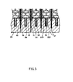
- FIG.3 is a partially enlarged view of a cross section of a fuel cell stack disclosed in Patent Literature 9.
- a fuel cell stack disclosed in Patent Literature 9 flat plate sections of a pair of adjacent metal separators 30 are in contact with each other, without a sealing member being arranged between the flat plate sections.
- separators 30 adhere with adhesive 28, and separators 30 and an MEA also adhere with adhesive 28.
- a first aspect of the present invention relates to a pair of separators for a fuel cell given below.
- a second aspect of the present invention relates to a fuel cell stack given below.
- a fluid flowing through channels of the pair of separators can be reliably sealed in. Therefore, use of a pair of separators for a fuel cell of the present invention can provide a fuel cell stack that prevents reaction gases and a coolant from leaking to outside.
- a fuel cell stack of the present invention includes a cell assembly.
- the cell assembly is a stack of unit fuel cells, each of the unit fuel cell being composed of a membrane electrode assembly (hereinafter also referred to as "MEA") and a pair of separators sandwiching the MEA.
- MEA membrane electrode assembly
- the fuel cell stack of the present invention may further include end plates sandwiching a current collector and the cell assembly (see FIG.4 ).
- the MEA includes a polymer electrolyte membrane and a pair of catalyst electrodes composed of a fuel electrode and an air electrode that sandwich the polymer electrolyte membrane.
- Respective pair of catalyst electrodes preferably include a catalyst layer being in contact with the polymer electrolyte membrane and a gas diffusion layer stacked on the catalyst layer.
- the polymer electrolyte membrane is a polymer membrane which selectively transports protons in a humidified state.
- the material of the polymer electrolyte membrane is not particularly limited so long as the material can selectively allow hydrogen ions to pass through. Examples of such materials include fluorine polymer electrolyte membranes and hydrocarbon polymer electrolyte membranes. Specific examples of fluorine polymer electrolyte membranes include NAFION® membranes (DuPont), FLEMION® membranes (Asahi Glass Co., Ltd.), ACIPLEX® membranes (Asahi Kasei Corporation), and GORE-SELECT® membranes (Japan Gore-Tex Inc.).
- the catalyst layer contains a catalyst which promotes an oxidation-reduction reaction of hydrogen and oxygen.
- the catalyst layer is not particularly limited so long as it is electrically conductive and is catalytically active for the oxidation-reduction reaction of hydrogen and oxygen.
- the catalyst layer at an air electrode contains as a catalyst platinum, platinum-cobalt alloy, platinum-cobalt-nickel alloy or the like.
- the catalyst layer at a fuel electrode contains as a catalyst platinum, platinum-ruthenium alloy or the like.
- the catalyst layer contains carbon fine particles (e.g., acetylene black, Ketjen Black or Vulcan) supporting the corresponding catalyst, and water-repellent resin such as polytetrafluoroethylene (PTFE) or the like.
- carbon fine particles e.g., acetylene black, Ketjen Black or Vulcan
- water-repellent resin such as polytetrafluoroethylene (PTFE) or the like.
- the gas diffusion layer is a conductive porous layer.
- the material of the gas diffusion layer is not particularly limited so long as it is conductive and can diffuse reaction gas.
- the gas diffusion layer may be composed of a gas diffusion base material layer for diffusing gas supplied from separators to the catalyst layer, and a carbon coat layer for improving attachment between the gas diffusion base material layer and the catalyst layer.
- the MEA may further include a frame.
- the frame is a component for covering the outer edges of a polymer electrolyte membrane and catalyst electrodes to support the polymer electrolyte membrane and the catalyst electrodes.
- the frame accommodates a polymer electrolyte membrane and catalyst electrodes so that the catalyst electrodes are in contact with a pair of separators.
- the frame preferably has heat resistance and acid resistance, and is generally made of a resin.
- frame material include polypropylene, polyphenylene sulfide, and polypropylene glycol.
- the frame includes reaction gas manifold holes for intaking and discharging reaction gases (fuel gas and oxidizing gas) and coolant manifold holes for intaking and discharging a coolant.
- the frame may be formed by 1) providing a mold having a cavity in a shape of the frame, and 2) filling the cavity of the mold with any of the above-described frame materials and cooling the material for solidification.
- the separator is a conductive member having channels for supplying reaction gases to the MEA, and a channel for supplying a coolant to cool a fuel cell.
- the separator may be manufactured by machine processing a conductive plate for a channel, or may be manufactured by pressing a conductive plate for a channel (hereinafter, simply referred to as "wave-shaped separator").
- the separator is preferably a wave-shaped separator.
- the wave-shaped separator includes at its center a corrugated plate section that is molded into a wave shape, and at its outer edge a flat plate section that encloses the center (see FIG.5 ).
- the corrugated plate section has a wave-shape cross section, with the thickness of the conductive plate constituting the corrugated plate section being constant.
- the conductive plate constituting the flat plate section is flat.
- the wave-shaped separator may be manufactured by pressing a metal plate or a carbon sheet.
- the wave-shaped separator manufactured by pressing a metal plate is also called a metal separator.
- Each separator includes reaction gas manifold holes for supplying and discharging reaction gases (fuel gas and oxidizing gas) and coolant manifold holes for supplying and discharging a coolant.
- each separator has front and rear surfaces.
- front surface of a separator refers to a surface facing an MEA and “rear surface of the separator” refers to a surface of the separator opposite from the front surface.
- the corrugated plate section on the front surface constitutes a reaction gas channel
- the corrugated plate section on the rear surface constitutes a coolant channel
- a feature of the present invention lies in a structure of two metal separators arranged adjacent to each other as described above (hereinafter simply referred to as "a pair of separators").
- the structure of a pair of separators of the present invention will be described in detail below in the section titled "2. Pair of separators for a fuel cell.”
- a pair of separators of the present invention includes adjacent two separators (first and second separators) and sealing members in a fuel cell stack.
- the first and second separators are arranged on top of each other so that their respective rear surfaces (surfaces on which a coolant channel is formed) face each other.
- a coolant channel is formed between the pair of separators.
- the first and second separators are arranged on top of each other so that the flat plate section of the first separator and the flat plate section of the second separator are in contact with each other (see FIG.6B ).
- the flat plate section of the first separator and the flat plate section of the second separator do not adhere to each other.
- a rib of a corrugated plate section of the first separator is preferably in contact with a rib of a corrugated plate section of the second separator, but the ribs of the corrugated plate sections of the first separator and the second separator do not adhere to each other, as is the case with the flat plate sections.
- the first and second separators do not adhere to each other, allowing easier disassembly of a fuel cell stack. Therefore, with the fuel cell stack of the present invention, it is easy to replace old separators from the stack and recycle separators.
- part of the flat plate section of the second separator protrudes outwardly beyond the edge of the flat plate section of the first separator (see FIG.6B ).
- a region of the flat plate section of the second separator that protrudes outwardly beyond the edge of the flat plate section of the first separator is also referred to as "protruding region”.
- the pair of separators of the present invention include sealing members.
- the sealing members include at least sealing members A, B, and C.
- the material of the sealing member is not particularly limited so long as it has elasticity, and may be thermosetting materials or thermoplastic materials. Examples of thermosetting materials include silicone and EPDM. Examples of thermoplastic materials include elastomers.
- Respective sealing members are secured on the flat plate section of a separator. Each sealing member seals a space between an MEA and a separator by being pressed against the MEA with a fastening pressure (see FIG.8A ).
- Sealing member A is arranged on the flat plate section on the front surface of the first separator, and seals in reaction gas flowing through a reaction gas channel of the first separator (hereinafter also simply referred to as "first reaction gas”) (see FIG.8A ).
- Sealing member B is arranged on the flat plate section on the front surface of the second separator, and seals in reaction gas flowing through a reaction gas channel of the second separator (hereinafter also simply referred to as "second reaction gas”) (see FIG.8A ).
- Sealing member C is arranged at the outer side of the fuel cell stack, which is outside the edge of the first separator, and seals in a coolant flowing through a coolant channel formed by the first and second separators (a coolant channel formed between the pair of separators by arranging the first separator and the second separator on top of each other) (see FIG.8A ).
- sealing member C is arranged on the protruding region on the rear surface of the second separator.
- sealing member C can be firmly supported. Accordingly, when a pressure is applied to a cell assembly in the direction along which unit fuel cells are stacked, sealing member C can be prevented from being deformed (see FIG.8C ).
- the pair of separators of the present invention preferably further includes sealing member D (see Embodiment 2). Further, in the pair of separators of the present invention, it is in particular preferable that all sealing members be integrally molded to constitute an integrally-molded sealing member (see Embodiment 3).
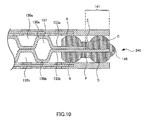
- each sealing member be in line contact with the MEA (see FIG.10 ).
- the integrally-molded sealing member is in surface contact with the MEA, there is a likelihood that a fastening pressure to be applied to the sealing member is dispersed, impairing the channel's property for sealing in a fluid (see FIG.11 ).
- fluids are sealed in by a fastening pressure to be applied to sealing members, so that, when the sealing members have deteriorated, the channel's property for sealing in a fluid will not be impaired so long as the fastening pressure is not weakened.
- a fluid is sealed in by adhesive force of adhesive 28 as with the conventional fuel cell stack shown in FIG.3 , deteriorated adhesive 28 will impair the channel's property for sealing in a fluid.
- FIG.4 is a perspective view of fuel cell stack 100 according to Embodiment 1 of the present invention.
- fuel cell stack 100 of Embodiment 1 includes multiple unit fuel cells 120 that are stacked.
- a stack of unit fuel cells (cell assembly) is sandwiched between two end plates 107 and secured by fastening bolts 109 and nuts 111.
- fuel cell stack 100 includes first reaction gas supply port 101, coolant supply port 102, second reaction gas supply port 103, first reaction gas discharge port 104, coolant discharge port 105, and second reaction gas discharge port 106, in one of end plates 107.
- First reaction gas supply port 101 is connected to a first reaction gas supply manifold
- coolant supply port 102 is connected to a coolant supply manifold
- second reaction gas supply port 103 is connected to a second reaction gas supply manifold.
- first reaction gas discharge port 104 is connected to a first reaction gas discharge manifold
- coolant discharge port 105 is connected to a coolant discharge manifold
- second reaction gas discharge port 106 is connected to a second reaction gas discharge manifold.
- FIG.5 is an exploded perspective view of unit fuel cell 120 included in fuel cell stack 100 according to Embodiment 1.
- unit fuel cell 120 is composed of membrane electrode assembly (MEA) 121 and a pair of metal separators 130 sandwiching MEA 121.
- MEA 121 includes frame 123 for covering the outer edges of a polymer electrolyte membrane and catalyst electrodes, and for supporting the polymer electrolyte membrane and the catalyst electrodes.
- Metal separator 130 includes at its center corrugated plate section 131 that is molded into a wave shape, and at its outer edge flat plate section 133 that encloses corrugated plate section 131. Further, metal separator 130 includes reaction gas channel 135 on the front surface (surface in contact with MEA 121), and includes coolant channel 137 for allowing a cloolant to flow on the rear surface.
- FIG.6A is a cross-sectional view of fuel cell stack 100 of FIG.4 taken along dashed dotted line ⁇ .
- FIG.6B is an enlarged view of a region enclosed by square X drawn by a broken line in fuel cell stack 100 of FIG.6A .
- adjacent metal separators 130 constitutes a pair of separators 140.
- a pair of separators 140 of the present embodiment will be described below with reference to FIG.6B
- a pair of separators 140 include first metal separator 130a, second metal separator 130b, sealing members A, B and C.
- First metal separator 130a and second metal separator 130b are arranged on top of each other so that their respective rear surfaces (surfaces on which a coolant channel is formed) face each other.
- coolant channel 137 is formed between the pair of separators.
- flat plate section 133a of first metal separator 130a is in contact with flat plate section 133b of second metal separator 130b.
- part of flat plate section 133b of second metal separator 130b protrudes outwardly beyond the edge of flat plate section 133a of first metal separator 130a.
- Sealing member A is arranged on flat plate section 133a on the front surface of first metal separator 130a to seal in the first reaction gas.
- Sealing member B is arranged on flat plate section 133b on the front surface of second metal separator 130b to seal in the second reaction gas.
- Sealing member C is arranged on protruding region 141 on the rear surface of second metal separator 130b to seal in a coolant flowing through coolant channel 137.
- protrusion 125 is formed on frame 123 at a position corresponding to the rear surface of sealing member C.
- sealing member B is positioned opposite to sealing member A with respect to the first and second metal separators, but sealing member B may be positioned opposite to sealing member C with respect to the second metal separator as shown in FIG.6C .
- protrusion 125 is formed on frame 123 at a position corresponding to the rear surface of sealing member A.
- FIGs.6A, 6B and 6C have described an embodiment where a separator is made of metal (wave-shaped separator), but the separator may be separator 130 manufactured by machine processing a conductive plate made of, for example, carbon, as shown in FIG.7 .
- FIG.8A is an enlarged view of a pair of separators 140 shown in FIG.6B .
- first reaction gas 136a flowing through reaction gas channel 135a of first metal separator 130a is sealed in by sealing member A.
- second reaction gas 136b flowing through reaction gas channel 135b of second metal separator 130b is sealed in by sealing member B.
- Coolant 1.39 flowing through coolant channel 137 may leak through a gap between first metal separator 130a and second metal separator 130b to outside. This is because it is technically difficult to make flat plate section 133 of metal separator 130 complete flat, and thus it is inevitable that a fine gap appears between flat plate section 133a and flat plate section 133b.
- sealing member C is arranged on protruding region 141 on the rear surface of the second metal separator to seal in coolant 139 by sealing member C, preventing coolant 139 from leaking outside a fuel cell stack.
- space H is a closed space, and thus there is no influence of the leaked coolant on performance of the fuel cell.
- the flat plate sections of the first metal separator and the second metal separator are in contact with each other, so that the separators will not be deformed even when a fastening pressure is applied to the fuel cell stack. Further, by making part of the second metal separator the protruding region and arranging sealing member C for sealing in a coolant on the rear surface of the protruding region, coolant leakage can be prevented.
- coolant 139 leaks outside fuel cell stack 100 after leaking from a gap between first metal separator 130a and second metal separator 130b.
- sealing member C is not arranged on a separator as shown in FIG.8C .
- sealing member C is preferably arranged on the protruding region of the second metal sep arator.
- Embodiment 2 will describe an embodiment where a pair of separators further include sealing member D.
- FIG.9 is a cross-sectional view of a pair of separators 240 according to Embodiment 2. Components identical to those of a pair of separators 140 of Embodiment 1 are given the same reference signs and descriptions are not provided.
- a pair of separators 240 of Embodiment 2 include sealing member D arranged on flat plate section 133b of the front surface of second metal separator 130b. Further, sealing member D is arranged at a position outside sealing member B (outer edge side of a fuel cell stack). In FIG.9 , sealing member D is arranged in protruding region 141 on the front surface of second metal separator 130b.
- sealing member A is positioned opposite to sealing member B with respect to the first and second metal separators, and sealing member C is positioned opposite to sealing member D with respect to the second metal separator.
- the second reaction gas can be double-sealed in by sealing members B and D.
- the channel's reliability for sealing in the second reaction gas can be further enhanced.
- fuel gas is preferably the second reaction gas to be double-sealed in.
- the present embodiment provides an effect of further improving the channel's reliability for sealing in a gas by double-sealing in reaction gas for which leakage requires to be more strictly controlled, in addition to the effects of Embodiment 1.
- Embodiments 1 and 2 have described an embodiment where respective sealing members are separated.
- Embodiment 3 will describe an embodiment where respective sealing members are integrally molded.
- FIG.10 is a cross-sectional view of a pair of separators 340 according to Embodiment 3.
- a pair of separators 340 of Embodiment 3 are the same as a pair of separators 240 of Embodiment 2, except that respective sealing members are integrally molded.
- Components identical to those of a pair of separators 240 of Embodiment 1 are given the same reference signs and descriptions are not provided.
- a pair of separators 340 of Embodiment 3 include protector 145 covering the edge of second metal separator 130b.
- the front surface and rear surface of a metal separator are surface-treated and thus are hard to deteriorate.
- the edge of a metal separator is not necessarily surface-treated, and thus may deteriorate due to generation of rust, or the like.
- sealing members A, B, C, and D and protector 145 are integrally molded using the same material.
- first metal separator 130a and second metal separator 130b can be secured with flat plate sections of the first and second metal separators being arranged on top of each other. Accordingly, the relative position of first metal separator 130a and second metal separator 130b can be fixed, improving assembly accuracy of a fuel cell stack.
- a pair of separators 340 can be treated as a single component, improving handling characteristics of a pair of separators 340.
- FIG.12 is a plan view of a pair of separators 340 according to Embodiment 3, viewed from the first metal separator side.
- a pair of separators 340 include first reaction gas supply manifold hole 161, coolant supply manifold hole 162, second reaction gas supply manifold hole 163, first reaction gas discharge manifold hole 164, coolant discharge manifold hole 165, and second reaction gas discharge manifold hole 166.
- Bold line X enclosing the outer edge of a pair of separators 340 indicates integrated sealing members A, B, C, and D.
- a pair of separators 340 include sealing member Z arranged on the outer edge of each manifold hole.
- FIG.13A is a cross-sectional view of a pair of separators 340 of FIG.12 taken along dashed dotted line ⁇ .
- FIG.13A shows a pair of separators 340 sandwiched between two MEAs 121.
- cross sections of a pair of separators 340 in the vicinity of first reaction gas supply manifold hole 161 include first reaction gas communication section 310 that allows gas to communicate between first reaction gas supply manifold hole 161 and first reaction gas channel 135a.
- First reaction gas communication section 310 include a support member for preventing communication section 310 from being pressed to become narrower via sealing member Z.
- the support member may be a protrusion formed on frame 123, a protrusion formed on first metal separator 130a, or a spacer arranged between frame 123 and first metal separator 130a.
- FIG.13B is a cross-sectional view of a pair of separators 340 of FIG.12 taken along dashed dotted line ⁇ .
- FIG.13B shows a pair of separators 340 sandwiched between two MEAs 121.
- cross sections of a pair of separators 340 in the vicinity of coolant supply manifold hole 162 include coolant communication section 311 that allows a coolant to communicate between coolant supply manifold hole 162 and coolant channel 137.
- coolant communication section 311 includes a support member for preventing coolant communication section 311 from being pressed to become narrower via sealing member Z.
- the support member may be a protrusion formed on first metal separator 130a or second metal separator 130b, or a spacer arranged between first metal separator 130a and second metal separator 130b.
- FIG.13C is a cross-sectional view of a pair of separators 340 of FIG.12 taken along dashed dotted line y.
- FIG.13C shows a pair of separators 340 sandwiched between two MEAs 121.
- cross sections of a pair of separators 340 in the vicinity of second reaction gas supply manifold hole 163 include second reaction gas communication section 312 that allows gas to flow from second reaction gas supply manifold hole 163 to second reaction gas channel 135b.
- second reaction gas 136b flowing through second reaction gas supply manifold hole 163 flows through second reaction gas communication section 312 into second reaction gas channel 135b.
- second reaction gas communication section 312 includes a support member for preventing second reaction gas communication section 312 from being pressed to become narrower via sealing member Z.
- the method of manufacturing a pair of separators 340 of the present embodiment include:
- FIG.14A shows the first step. As shown in FIG.14A , in the first step, first metal separator 130a and second metal separator 130b are provided and then arranged on top of each other so that rear surfaces of first metal separator 130a and second metal separator 130b face each other.
- FIG.14B shows the second step. As shown in FIG.14B , in the second step, the above arranged first metal separator 130a and second metal separator 130b are put in mold 150 with a cavity of the shape of the sealing members and protector 145.
- first metal separator 130a and second metal separator 130b be secured in the cavity by securing member 151.
- securing flat plate sections 133 of the above arranged first metal separator 130a and second metal separator 130b in this way it is possible to prevent the relative position of first metal separator 130a and second metal separator 130b from being deviated or to prevent the metal separators from being deformed, when a material (resin) of sealing members is injected into the cavity.
- FIG.14C shows the third step. As shown in FIG.14C , in the third step, material 153 of the sealing members and protector 145 is injected in the cavity to integrally mold sealing members A, B, C and D and protector 145.
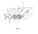
- FIG.15 is a perspective view of a pair of separators 340 thus manufactured.
- an integrally molded sealing member includes openings 147 at places where securing members have been arranged. Part of the flat plate section on the front surface of first metal separator 130a or second metal separator 130b is exposed through opening 147.
- the relative position of the first metal separator and the second metal separator can be fixed, so that the present embodiment provides an effect of improving accuracy of assembly of a fuel cell stack, in addition to the effects of Embodiment 2.
- the first metal separator and the second metal separator it is possible to treat a pair of separators as a single component, thus improving handling characteristics of the pair of separators.
- integrally molding sealing sections and a protector makes it possible to form the protector and all sealing members in one step.
- Embodiment 4 will describe an embodiment where a metal separator has a hole.
- FIG.16 is a cross-sectional view of a pair of separators 440 according to Embodiment 4.
- a pair of separators 440 of Embodiment 4 are the same as a pair of separators 340 of Embodiment 3, except that a metal separator has a hole.
- Components identical to those of a pair of separators 340 of Embodiment 3 are given the same reference signs and descriptions are not provided.
- flat plate section 133a of first metal separator 130a includes hole 134a filled with an integrally molded sealing member.
- flat plate section 133b of second metal separator 130b includes hole 134b filled with the integrally molded sealing member.
- the integrally molded sealing member is secured to the metal separators more reliably.
- Embodiment 5 will describe an embodiment where a metal separator has a protrusion.
- FIG.17 is a cross-sectional view of a pair of separators 540 according to Embodiment 5.
- a pair of separators 540 of Embodiment 5 are the same as a pair of separators 340 of Embodiment 3, except that a metal separator has a protrusion.
- Components identical to those of a pair of separators 340 of Embodiment 3 are given the same reference signs and descriptions are not provided.
- flat plate section 133a of first metal separator 130a has protrusion 138a embeded in an integrally molded sealing member.
- flat plate section 133b of second metal separator 130b has protrusion 138b embeded in the integrally molded sealing member.
- the integrally molded sealing member is secured to the metal separators more reliably.
- a pair of separators integrated with a sealing member according to the present invention has high sealing reliability, therefore can regulate gases or a coolant flowing through separator channels to reliably prevent gases and a coolant from being mixed.
- the fuel cell stack according to the present invention is used for portable power sources, power sources for electric vehicles, and household cogeneration systems, for example.
Abstract
Description
- The present invention relates to a polymer fuel cell stack and a pair of separators for a polymer fuel cell.
- A polymer fuel cell stack (hereinafter also simply referred to as "fuel cell stack") includes a cell assembly in which multiple unit fuel cells are stacked and connected in series. Each unit fuel cell is composed of a membrane electrode assembly (hereinafter also referred to as "MEA") and a pair of separators arranged at both sides of the MEA. The MEA includes a polymer electrolyte membrane and a pair of catalyst electrodes (fuel electrode and air electrode) arranged at both sides of the polymer electrolyte membrane. The separator includes gas channels for supplying fuel gas or oxidizing gas to the MEA. The separator further includes a coolant channel for allowing a coolant to flow for controlling the temperature of the fuel cell stack under operation. Respective unit fuel cells are electrically connected via the pair of separators.
- Further, in the fuel cell stack, in order to ensure sealing between unit fuel cells and decrease contact resistance between unit fuel cells, a pressure is applied in the direction along which the unit fuel cells are stacked (hereinafter also referred to as "fastening pressure").
- In recent years, a method is suggested for manufacturing separators by pressing metal plates into a wave shape. The separator manufactured by pressing a metal plate is called a metal separator.
- As described above, the separator includes channels for allowing reaction gases (fuel gas and oxidizing gas) and a coolant to flow. Because fuel gas, oxidizing gas, and a coolant need to be supplied to their respective separate channels, a fuel cell stack includes sealing members for hermetically sealing the channels so as to prevent the respective channels from communicating with one another (for example, see
Patent Literatures 1 to 8). - According to
Patent Literatures 1 to 7, sealing members are stacked between an MEA and a separator and between adjacent separators to seal in reaction gases and a coolant. However, fuel cell stacks disclosed inPatent Literatures 1 to 7 have a disadvantage of deviating the relative position of separators or deviating the positions at which sealing members are arranged. - A technique for overcoming such a problem is shown in
FIG.1 (for example, see Patent Literature 8).FIG.1 is a cross-sectional view of an end of a pair of metal separators disclosed in Patent Literature 8. InFIG.1 , in a fuel cell stack, adjacent two metal separators (first metal separator 1 and second metal separator 2) andsealing member 10 are integrated.First metal separator 1 includes corrugated plate section 5 and flat plate section 6, andsecond metal separator 2 includescorrugated plate section 7 and flat plate section 8. Flat plate section 6 is not in contact with flat plate section 8, and a sealing member is arranged between them. - As described above, by integrating metal separators and a sealing member, it is possible to prevent the positions at which sealing members are arranged from being deviated, improving reliability of sealing. Further, by integrating metal separators and a sealing member, the relative position of the metal separators can be fixed, facilitating easier assembly of a fuel cell stack.
- However, in a pair of separators integrated with a sealing member with the sealing member being arranged between flat plate sections 6 and 8 such as that shown in Patent Literature 8, when a fastening pressure is applied to sealing
member 10 in the arrow direction, ends ofmetal separators metal separators FIG.2 . When the metal separators are deformed, sealing reliability may decrease and contact resistance between unit fuel cells may increase. For this reason, in a fuel cell stack having a pair of separators such as that disclosed in Patent Literature 8, reaction gases and a coolant may leak to outside or electrically-output of the fuel cell stack may lower. - To overcome this problem, in adjacent fuel cell stacks, flat plate sections of metal separators may be arranged on top of each other so as to be in contact with each other (for example, see Patent Literature 9).
-
FIG.3 is a partially enlarged view of a cross section of a fuel cell stack disclosed in Patent Literature 9. As shown inFIG.3 , in a fuel cell stack disclosed in Patent Literature 9, flat plate sections of a pair ofadjacent metal separators 30 are in contact with each other, without a sealing member being arranged between the flat plate sections. By making flat plate sections of a pair of adjacent metal separators in contact with each other in this way, the separators are prevented from being deformed even when a pressure (fastening pressure) is applied to the fuel cell stack in the direction along which cells are stacked. - Further, in the fuel cell stack shown in
FIG.3 , a pair ofadjacent separators 30 adhere withadhesive 28, andseparators 30 and an MEA also adhere withadhesive 28. -
-
PTL 1
Japanese Patent No.3868810 -
PTL 2
Japanese Patent Application Laid-Open No.2004-319279 - PTL 3
Japanese Patent Application Laid-Open No.2006-216294 - PTL 4
Japanese Patent Application Laid-Open No.2005-243286 - PTL 5
U.S. Patent Application Publication No.2006/0024561 - PTL 6
U.S. Patent Application Publication No.2006/0088752 -
PTL 7
U.S. Patent Application Publication No.2008/0187812 - PTL 8
Japanese Patent Application Laid-Open No.2007-172992 - PTL 9
Japanese Patent Application Laid-Open No.2001-15132 - However, in the case where flat plate sections of a pair of adjacent metal separators are made in contact with each other without a sealing member being arranged between the flat plate sections as shown in
FIG.3 , a coolant flowing between the pair of adjacent metal separators may leak through a gap between the flat plate sections. This is because it is technically difficult to make a flat plate section of a metal separator complete flat, and thus it is inevitable that a fine gap appears between two flat plate sections which are in contact with each other. As described above, in a fuel cell stack having metal separators, it has been difficult to reliably seal in fluids (reaction gases and coolants). - It is therefore an object of the present invention to provide a pair of separators for a fuel cell that is integrated with a sealing member that maintains sealing reliability.
- A first aspect of the present invention relates to a pair of separators for a fuel cell given below.
- [1] A pair of separators for a fuel cell comprising:
- a first separator and a second separator, each of the first separator and the second separator having a front surface and a rear surface and having at a center of the separator a corrugated plate section molded into a wave shape and at an outer edge of the separator a flat plate section enclosing the corrugated plate section,
- the corrugated plate section on the front surface constituting a reaction gas channel,
- the corrugated plate section on the rear surface constituting a coolant channel,
- the first separator and the second separator being arranged on top of each other so that the rear surfaces of the first separator and the second separator face each other and that the flat plate section of the first separator and the flat plate section of the second separator are in contact with each other,
- the flat plate section of the second separator protruding outwardly beyond the edge of the flat plate section of the first separator;
- sealing member A arranged on the flat plate section on the front surface of the first separator;
- sealing member B arranged on the flat plate section on the front surface of the second separator; and
- sealing member C arranged on a region on the flat plate section on the rear surface of the second separator, the region protruding outwardly beyond the flat plate section of the first separator.
- [2] The pair of separators for a fuel cell according to [1], further comprising sealing member D arranged on the flat plate section on the front surface of the second separator and arranged at a position outside sealing member B,
wherein the sealing member A is positioned opposite to sealing member B with respect to the pair of separators, and
the sealing member C is positioned opposite to sealing member D with respect to the second separator. - [3] The pair of separators for a fuel cell according to [2],
wherein the first separator is an air electrode separator, and
the second separator is a fuel electrode separator. - [4] The pair of separators for a fuel cell according to any one of [2] and [3], further comprising a protector covering an edge of the second separator,
wherein the sealing members A, B, C, and D, and the protector are integrally molded. - [5] The pair of separators for a fuel cell according to [4],
wherein the integrally molded sealing member has an opening, and
part of the flat plate section of the first separator or the second separator is exposed through the opening. - [6] The pair of separators for a fuel cell according to any one of [4] and [5],
wherein the flat plate section of the first separator has a hole filled with the integrally molded sealing member, and
the flat plate section of the second separator has a hole filled with the integrally molded sealing member. - [7] The pair of separators for a fuel cell according to any one of [4] and [5],
wherein the flat plate section of the first separator has a protrusion embedded in the integrally molded sealing member, and
the flat plate section of the second separator has a protrusion embeded in the integrally molded sealing member. - A second aspect of the present invention relates to a fuel cell stack given below.
- [8] A fuel cell stack comprising:
- a membrane electrode assembly having a polymer electrolyte membrane and a pair of catalyst electrodes, the pair of catalyst electrodes including a fuel electrode and an air electrode sandwiching the polymer electrolyte membrane; and
- the pair of separators for a fuel cell according to any one of any one of [1] to [7].
- [9] The fuel cell stack according to [8],
wherein the membrane electrode assembly further comprises a frame covering outer edges of the polymer electrolyte membrane and the catalyst electrodes. - With a pair of separators for a fuel cell of the present invention, a fluid flowing through channels of the pair of separators can be reliably sealed in. Therefore, use of a pair of separators for a fuel cell of the present invention can provide a fuel cell stack that prevents reaction gases and a coolant from leaking to outside.
-
-
FIG.1 is a cross-sectional view of a conventional pair of separators for a fuel cell that are integrated with a sealing member; -
FIG.2 is a cross-sectional view of a conventional pair of separators for a fuel cell that are integrated with a sealing member when a pressure has been applied to the sealing member; -
FIG.3 is a partially enlarged view of a cross section of a conventional fuel cell stack; -
FIG.4 is a perspective view of a fuel cell stack according toEmbodiment 1; -
FIG.5 is an exploded perspective view of an unit fuel cell included in a fuel cell stack according toEmbodiment 1; -
FIGs.6A to 6C are cross-sectional views of a fuel cell stack according toEmbodiment 1; -
FIG.7 is a cross-sectional view of a fuel cell stack according toEmbodiment 1 having a separator made by machining; -
FIGs.8A to 8C show flow of reaction gases and a coolant flowing in a fuel cell stack; -
FIG.9 is a cross-sectional view of a pair of separators for a fuel cell according toEmbodiment 2; -
FIG.10 is a cross-sectional view of a pair of separators for a fuel cell according to Embodiment 3; -
FIG.11 is a cross-sectional view of a pair of separators for a fuel cell in which a sealing member is in surface contact with the pair of separators; -
FIG.12 is a plan view of a pair of separators for a fuel cell according to Embodiment 3; -
FIGs.13A to 13C are cross-sectional views of a pair of separators for a fuel cell according to Embodiment 3; -
FIGs.14A to 14C show a manufacturing process of a pair of separators for a fuel cell according to Embodiment 3; -
FIG.15 is a perspective view of a pair of separators for a fuel cell according to Embodiment 3; -
FIG.16 is a cross-sectional view of a pair of separators for a fuel cell according to Embodiment 4; and -
FIG.17 is a cross-sectional view of a pair of separators for a fuel cell according to Embodiment 5. - A fuel cell stack of the present invention includes a cell assembly. The cell assembly is a stack of unit fuel cells, each of the unit fuel cell being composed of a membrane electrode assembly (hereinafter also referred to as "MEA") and a pair of separators sandwiching the MEA. The fuel cell stack of the present invention may further include end plates sandwiching a current collector and the cell assembly (see
FIG.4 ). - The MEA includes a polymer electrolyte membrane and a pair of catalyst electrodes composed of a fuel electrode and an air electrode that sandwich the polymer electrolyte membrane. Respective pair of catalyst electrodes preferably include a catalyst layer being in contact with the polymer electrolyte membrane and a gas diffusion layer stacked on the catalyst layer.
- The polymer electrolyte membrane is a polymer membrane which selectively transports protons in a humidified state. The material of the polymer electrolyte membrane is not particularly limited so long as the material can selectively allow hydrogen ions to pass through. Examples of such materials include fluorine polymer electrolyte membranes and hydrocarbon polymer electrolyte membranes. Specific examples of fluorine polymer electrolyte membranes include NAFION® membranes (DuPont), FLEMION® membranes (Asahi Glass Co., Ltd.), ACIPLEX® membranes (Asahi Kasei Corporation), and GORE-SELECT® membranes (Japan Gore-Tex Inc.).
- The catalyst layer contains a catalyst which promotes an oxidation-reduction reaction of hydrogen and oxygen. The catalyst layer is not particularly limited so long as it is electrically conductive and is catalytically active for the oxidation-reduction reaction of hydrogen and oxygen. The catalyst layer at an air electrode contains as a catalyst platinum, platinum-cobalt alloy, platinum-cobalt-nickel alloy or the like. The catalyst layer at a fuel electrode contains as a catalyst platinum, platinum-ruthenium alloy or the like.
- The catalyst layer contains carbon fine particles (e.g., acetylene black, Ketjen Black or Vulcan) supporting the corresponding catalyst, and water-repellent resin such as polytetrafluoroethylene (PTFE) or the like.
- The gas diffusion layer is a conductive porous layer. The material of the gas diffusion layer is not particularly limited so long as it is conductive and can diffuse reaction gas. The gas diffusion layer may be composed of a gas diffusion base material layer for diffusing gas supplied from separators to the catalyst layer, and a carbon coat layer for improving attachment between the gas diffusion base material layer and the catalyst layer.
- The MEA may further include a frame. The frame is a component for covering the outer edges of a polymer electrolyte membrane and catalyst electrodes to support the polymer electrolyte membrane and the catalyst electrodes. The frame accommodates a polymer electrolyte membrane and catalyst electrodes so that the catalyst electrodes are in contact with a pair of separators.
- The frame preferably has heat resistance and acid resistance, and is generally made of a resin. Examples of such frame material include polypropylene, polyphenylene sulfide, and polypropylene glycol.
- The frame includes reaction gas manifold holes for intaking and discharging reaction gases (fuel gas and oxidizing gas) and coolant manifold holes for intaking and discharging a coolant.
- The frame may be formed by 1) providing a mold having a cavity in a shape of the frame, and 2) filling the cavity of the mold with any of the above-described frame materials and cooling the material for solidification.
- The separator is a conductive member having channels for supplying reaction gases to the MEA, and a channel for supplying a coolant to cool a fuel cell.
- According to the present invention, the separator may be manufactured by machine processing a conductive plate for a channel, or may be manufactured by pressing a conductive plate for a channel (hereinafter, simply referred to as "wave-shaped separator"). According to the present invention, the separator is preferably a wave-shaped separator. The wave-shaped separator includes at its center a corrugated plate section that is molded into a wave shape, and at its outer edge a flat plate section that encloses the center (see
FIG.5 ). The corrugated plate section has a wave-shape cross section, with the thickness of the conductive plate constituting the corrugated plate section being constant. On the other hand, the conductive plate constituting the flat plate section is flat. - The wave-shaped separator may be manufactured by pressing a metal plate or a carbon sheet. The wave-shaped separator manufactured by pressing a metal plate is also called a metal separator.
- Each separator includes reaction gas manifold holes for supplying and discharging reaction gases (fuel gas and oxidizing gas) and coolant manifold holes for supplying and discharging a coolant.
- Further, each separator has front and rear surfaces. Here, "front surface of a separator" refers to a surface facing an MEA and "rear surface of the separator" refers to a surface of the separator opposite from the front surface.
- In the case of the wave-shaped separator, the corrugated plate section on the front surface constitutes a reaction gas channel, and the corrugated plate section on the rear surface constitutes a coolant channel.
- As described above, in a fuel cell stack, these unit fuel cells are stacked and thus they are adjacent to each other. When unit fuel cells are adjacent to each other, a metal separator in one unit fuel cell and a metal separator in another unit fuel cell are adjacent to each other on the surfaces facing away the MEAs. A feature of the present invention lies in a structure of two metal separators arranged adjacent to each other as described above (hereinafter simply referred to as "a pair of separators"). The structure of a pair of separators of the present invention will be described in detail below in the section titled "2. Pair of separators for a fuel cell."
- As described above, a pair of separators of the present invention includes adjacent two separators (first and second separators) and sealing members in a fuel cell stack.
- According to a pair of separators of the present invention, the first and second separators are arranged on top of each other so that their respective rear surfaces (surfaces on which a coolant channel is formed) face each other. By arranging the first separator and the second separator on top of each other, a coolant channel is formed between the pair of separators. Further, according to the pair of separators of the present invention, the first and second separators are arranged on top of each other so that the flat plate section of the first separator and the flat plate section of the second separator are in contact with each other (see
FIG.6B ). However, the flat plate section of the first separator and the flat plate section of the second separator do not adhere to each other. Further, a rib of a corrugated plate section of the first separator is preferably in contact with a rib of a corrugated plate section of the second separator, but the ribs of the corrugated plate sections of the first separator and the second separator do not adhere to each other, as is the case with the flat plate sections. - In a conventional pair of separators, a flat plate section of a first separator and a flat plate section of a second separator are not in contact with each other, and a gap between the flat plate sections is filled with a sealing member (see
Fig.2 ). For this reason, when a pressure (hereinafter also referred to as "fastening pressure") is applied to a fuel cell stack in the direction along which cells are stacked, ends of separators may be deformed (seeFIG.2 ). On the other hand, when flat plate sections of separators are in contact with each other as with the present invention, ends of the separators will not be deformed even when a fastening pressure is applied to a fuel cell stack. - Further, according to the present invention, the first and second separators do not adhere to each other, allowing easier disassembly of a fuel cell stack. Therefore, with the fuel cell stack of the present invention, it is easy to replace old separators from the stack and recycle separators.
- Further, according to the present invention, part of the flat plate section of the second separator protrudes outwardly beyond the edge of the flat plate section of the first separator (see
FIG.6B ). Hereinafter, a region of the flat plate section of the second separator that protrudes outwardly beyond the edge of the flat plate section of the first separator is also referred to as "protruding region". - As described above, the pair of separators of the present invention include sealing members. The sealing members include at least sealing members A, B, and C. The material of the sealing member is not particularly limited so long as it has elasticity, and may be thermosetting materials or thermoplastic materials. Examples of thermosetting materials include silicone and EPDM. Examples of thermoplastic materials include elastomers. Respective sealing members are secured on the flat plate section of a separator. Each sealing member seals a space between an MEA and a separator by being pressed against the MEA with a fastening pressure (see
FIG.8A ). - Sealing member A is arranged on the flat plate section on the front surface of the first separator, and seals in reaction gas flowing through a reaction gas channel of the first separator (hereinafter also simply referred to as "first reaction gas") (see
FIG.8A ). Sealing member B is arranged on the flat plate section on the front surface of the second separator, and seals in reaction gas flowing through a reaction gas channel of the second separator (hereinafter also simply referred to as "second reaction gas") (seeFIG.8A ). - Sealing member C is arranged at the outer side of the fuel cell stack, which is outside the edge of the first separator, and seals in a coolant flowing through a coolant channel formed by the first and second separators (a coolant channel formed between the pair of separators by arranging the first separator and the second separator on top of each other) (see
FIG.8A ). - Further, sealing member C is arranged on the protruding region on the rear surface of the second separator. By arranging sealing member C on the protruding region in this way, sealing member C can be firmly supported. Accordingly, when a pressure is applied to a cell assembly in the direction along which unit fuel cells are stacked, sealing member C can be prevented from being deformed (see
FIG.8C ). - The pair of separators of the present invention preferably further includes sealing member D (see Embodiment 2). Further, in the pair of separators of the present invention, it is in particular preferable that all sealing members be integrally molded to constitute an integrally-molded sealing member (see Embodiment 3).
- Even when all of the sealing members are integrally molded, it is preferable that each sealing member be in line contact with the MEA (see
FIG.10 ). On the other hand, when the integrally-molded sealing member is in surface contact with the MEA, there is a likelihood that a fastening pressure to be applied to the sealing member is dispersed, impairing the channel's property for sealing in a fluid (seeFIG.11 ). - As described above, according to the present invention, by arranging the flat plate section of the first separator and the flat plate section of the second separator on top of each other, and arranging sealing member C on the protruding region on the rear surface of the second separator, fluids (reaction gases and a coolant) flowing through channels between a pair of separators can be reliably sealed in. A mechanism of sealing in fluids reliably will be described in detail in
Embodiment 1. - Further, according to the present invention, fluids are sealed in by a fastening pressure to be applied to sealing members, so that, when the sealing members have deteriorated, the channel's property for sealing in a fluid will not be impaired so long as the fastening pressure is not weakened. On the other hand, when a fluid is sealed in by adhesive force of adhesive 28 as with the conventional fuel cell stack shown in
FIG.3 , deteriorated adhesive 28 will impair the channel's property for sealing in a fluid. - Hereinafter, embodiments of the present invention will be described in detail with reference to the accompanying drawings.
-
FIG.4 is a perspective view offuel cell stack 100 according toEmbodiment 1 of the present invention. As shown inFIG.4 ,fuel cell stack 100 ofEmbodiment 1 includes multipleunit fuel cells 120 that are stacked. A stack of unit fuel cells (cell assembly) is sandwiched between twoend plates 107 and secured by fasteningbolts 109 and nuts 111. - Further,
fuel cell stack 100 includes first reactiongas supply port 101,coolant supply port 102, second reactiongas supply port 103, first reactiongas discharge port 104,coolant discharge port 105, and second reactiongas discharge port 106, in one ofend plates 107. First reactiongas supply port 101 is connected to a first reaction gas supply manifold,coolant supply port 102 is connected to a coolant supply manifold, and second reactiongas supply port 103 is connected to a second reaction gas supply manifold. Further, first reactiongas discharge port 104 is connected to a first reaction gas discharge manifold,coolant discharge port 105 is connected to a coolant discharge manifold, and second reactiongas discharge port 106 is connected to a second reaction gas discharge manifold. -
FIG.5 is an exploded perspective view ofunit fuel cell 120 included infuel cell stack 100 according toEmbodiment 1. As shown inFIG.5 ,unit fuel cell 120 is composed of membrane electrode assembly (MEA) 121 and a pair ofmetal separators 130 sandwichingMEA 121. As shown inFIG.5 ,MEA 121 includesframe 123 for covering the outer edges of a polymer electrolyte membrane and catalyst electrodes, and for supporting the polymer electrolyte membrane and the catalyst electrodes. -
Metal separator 130 includes at its center corrugatedplate section 131 that is molded into a wave shape, and at its outer edgeflat plate section 133 that encloses corrugatedplate section 131. Further,metal separator 130 includesreaction gas channel 135 on the front surface (surface in contact with MEA 121), and includescoolant channel 137 for allowing a cloolant to flow on the rear surface. -
FIG.6A is a cross-sectional view offuel cell stack 100 ofFIG.4 taken along dashed dotted line α.FIG.6B is an enlarged view of a region enclosed by square X drawn by a broken line infuel cell stack 100 ofFIG.6A . As shown inFIG.6B , infuel cell stack 100,adjacent metal separators 130 constitutes a pair ofseparators 140. A pair ofseparators 140 of the present embodiment will be described below with reference toFIG.6B - A pair of
separators 140 includefirst metal separator 130a,second metal separator 130b, sealing members A, B and C. -
First metal separator 130a andsecond metal separator 130b are arranged on top of each other so that their respective rear surfaces (surfaces on which a coolant channel is formed) face each other. By arrangingfirst metal separator 130a andsecond metal separator 130b on top of each other,coolant channel 137 is formed between the pair of separators. Further,flat plate section 133a offirst metal separator 130a is in contact withflat plate section 133b ofsecond metal separator 130b. - Further, part of
flat plate section 133b ofsecond metal separator 130b protrudes outwardly beyond the edge offlat plate section 133a offirst metal separator 130a. By arrangingflat plate section 133b ofsecond metal separator 130b so that part offlat plate section 133b protrudes outwardly beyond the edge offlat plate section 133a offirst metal separator 130a, protrudingregion 141 is formed. - Sealing member A is arranged on
flat plate section 133a on the front surface offirst metal separator 130a to seal in the first reaction gas. Sealing member B is arranged onflat plate section 133b on the front surface ofsecond metal separator 130b to seal in the second reaction gas. - Sealing member C is arranged on protruding
region 141 on the rear surface ofsecond metal separator 130b to seal in a coolant flowing throughcoolant channel 137. According to the present embodiment, to preventprotruding region 141 from being deformed by a pressure applied to sealing member C,protrusion 125 is formed onframe 123 at a position corresponding to the rear surface of sealing member C. - In
FIGs.6A and 6B , sealing member B is positioned opposite to sealing member A with respect to the first and second metal separators, but sealing member B may be positioned opposite to sealing member C with respect to the second metal separator as shown inFIG.6C . In that case, to preventflat plate sections protrusion 125 is formed onframe 123 at a position corresponding to the rear surface of sealing member A. - Further,
FIGs.6A, 6B and 6C have described an embodiment where a separator is made of metal (wave-shaped separator), but the separator may be separator 130 manufactured by machine processing a conductive plate made of, for example, carbon, as shown inFIG.7 . - Next, functions of sealing members (A, B, and C) will be described below with reference to
FIG.8A. FIG.8A is an enlarged view of a pair ofseparators 140 shown inFIG.6B . As shown inFIG.8A ,first reaction gas 136a flowing throughreaction gas channel 135a offirst metal separator 130a is sealed in by sealing member A. Further,second reaction gas 136b flowing throughreaction gas channel 135b ofsecond metal separator 130b is sealed in by sealing member B. - Coolant 1.39 flowing through
coolant channel 137 may leak through a gap betweenfirst metal separator 130a andsecond metal separator 130b to outside. This is because it is technically difficult to makeflat plate section 133 ofmetal separator 130 complete flat, and thus it is inevitable that a fine gap appears betweenflat plate section 133a andflat plate section 133b. - However, according to the present embodiment, sealing member C is arranged on protruding
region 141 on the rear surface of the second metal separator to seal incoolant 139 by sealing member C, preventingcoolant 139 from leaking outside a fuel cell stack. - Further, a coolant that has leaked to space H between sealing member A and sealing member C remains in space H. However, space H is a closed space, and thus there is no influence of the leaked coolant on performance of the fuel cell.
- As described above, according to the pair of fuel cell separators of
Embodiment 1, the flat plate sections of the first metal separator and the second metal separator are in contact with each other, so that the separators will not be deformed even when a fastening pressure is applied to the fuel cell stack. Further, by making part of the second metal separator the protruding region and arranging sealing member C for sealing in a coolant on the rear surface of the protruding region, coolant leakage can be prevented. - On the other hand, as shown in
FIG.8B , when a pair ofseparators 140 do not include sealing member C,coolant 139 leaks outsidefuel cell stack 100 after leaking from a gap betweenfirst metal separator 130a andsecond metal separator 130b. - Further, it may be possible to achieve an effect of preventing coolant leakage even when sealing member C is not arranged on a separator as shown in
FIG.8C . However, when sealing member C is not arranged on the separator, the position of sealing member C is deviated or sealing member C is deformed by a fastening pressure. For this reason, sealing member C is preferably arranged on the protruding region of the second metal sep arator. -
Embodiment 2 will describe an embodiment where a pair of separators further include sealing member D. -
FIG.9 is a cross-sectional view of a pair ofseparators 240 according toEmbodiment 2. Components identical to those of a pair ofseparators 140 ofEmbodiment 1 are given the same reference signs and descriptions are not provided. As shown inFIG.9 , a pair ofseparators 240 ofEmbodiment 2 include sealing member D arranged onflat plate section 133b of the front surface ofsecond metal separator 130b. Further, sealing member D is arranged at a position outside sealing member B (outer edge side of a fuel cell stack). InFIG.9 , sealing member D is arranged in protrudingregion 141 on the front surface ofsecond metal separator 130b. - According to the present embodiment, sealing member A is positioned opposite to sealing member B with respect to the first and second metal separators, and sealing member C is positioned opposite to sealing member D with respect to the second metal separator.
- As described above, according to the present embodiment, by further providing sealing member D, the second reaction gas can be double-sealed in by sealing members B and D. By this means, the channel's reliability for sealing in the second reaction gas can be further enhanced. Out of fuel gas and oxidizing gas, hydrogen contained in fuel gas has a smaller molecular weight than oxygen contained in oxidizing gas, so that hydrogen is more likely to leak. Further, because hydrogen gas is highly reactive, controlling the leakage of hydrogen gas is more important. Therefore, according to the present embodiment, fuel gas is preferably the second reaction gas to be double-sealed in. As described above, the present embodiment provides an effect of further improving the channel's reliability for sealing in a gas by double-sealing in reaction gas for which leakage requires to be more strictly controlled, in addition to the effects of
Embodiment 1. - Embodiments 1 and 2 have described an embodiment where respective sealing members are separated. Embodiment 3 will describe an embodiment where respective sealing members are integrally molded.
-
FIG.10 is a cross-sectional view of a pair ofseparators 340 according to Embodiment 3. A pair ofseparators 340 of Embodiment 3 are the same as a pair ofseparators 240 ofEmbodiment 2, except that respective sealing members are integrally molded. Components identical to those of a pair ofseparators 240 ofEmbodiment 1 are given the same reference signs and descriptions are not provided. - As shown in
FIG.10 , a pair ofseparators 340 of Embodiment 3 includeprotector 145 covering the edge ofsecond metal separator 130b. Generally, the front surface and rear surface of a metal separator are surface-treated and thus are hard to deteriorate. On the other hand, the edge of a metal separator is not necessarily surface-treated, and thus may deteriorate due to generation of rust, or the like, By providingprotector 145 for covering the edge of the second metal separator as with the present embodiment, the edge ofsecond metal separator 130b can be prevented from deteriorating. - Further, according to the present embodiment, sealing members A, B, C, and D and
protector 145 are integrally molded using the same material. By integrally molding sealing members and a protector in this way,first metal separator 130a andsecond metal separator 130b can be secured with flat plate sections of the first and second metal separators being arranged on top of each other. Accordingly, the relative position offirst metal separator 130a andsecond metal separator 130b can be fixed, improving assembly accuracy of a fuel cell stack. Further, by securingfirst metal separator 130a andsecond metal separator 130b, a pair ofseparators 340 can be treated as a single component, improving handling characteristics of a pair ofseparators 340. - Further, even in the case where respective sealing members are integrally molded as with the present embodiment, it is preferable that the respective sealing members be in line contact with the MEA. For this reason, it is preferable that region E of the integrated sealing member which connects sealing members A and C and region F of the integrated sealing member which connects sealing members B and D be not in contact with
MEA 121. - On the other hand, in the case where an integrally molded sealing member is in surface contact with the MEA as shown in
FIG.11 , a fastening pressure to be applied to the sealing member is dispersed, impairing the channel's property for sealing in a fluid. - Next, a structure in the vicinity of manifold holes of a pair of
separators 340 of the present embodiment will be described below with reference toFIG.12 andFIGs.13A to 13B . -
FIG.12 is a plan view of a pair ofseparators 340 according to Embodiment 3, viewed from the first metal separator side. As shown inFIG.12 , a pair ofseparators 340 include first reaction gassupply manifold hole 161, coolantsupply manifold hole 162, second reaction gassupply manifold hole 163, first reaction gasdischarge manifold hole 164, coolantdischarge manifold hole 165, and second reaction gasdischarge manifold hole 166. Bold line X enclosing the outer edge of a pair ofseparators 340 indicates integrated sealing members A, B, C, and D. Further, a pair ofseparators 340 include sealing member Z arranged on the outer edge of each manifold hole. -
FIG.13A is a cross-sectional view of a pair ofseparators 340 ofFIG.12 taken along dashed dotted line α. For the purpose of convenience,FIG.13A shows a pair ofseparators 340 sandwiched between two MEAs 121. As shown inFIG.13A , cross sections of a pair ofseparators 340 in the vicinity of first reaction gassupply manifold hole 161 include first reactiongas communication section 310 that allows gas to communicate between first reaction gassupply manifold hole 161 and firstreaction gas channel 135a. - As shown in
FIG.13A ,first reaction gas 136a flowing through first reaction gassupply manifold hole 161 flows through first reactiongas communication section 310 into firstreaction gas channel 135a. First reactiongas communication section 310 include a support member for preventingcommunication section 310 from being pressed to become narrower via sealing member Z. The support member may be a protrusion formed onframe 123, a protrusion formed onfirst metal separator 130a, or a spacer arranged betweenframe 123 andfirst metal separator 130a. -
FIG.13B is a cross-sectional view of a pair ofseparators 340 ofFIG.12 taken along dashed dotted line β. For the purpose of convenience,FIG.13B shows a pair ofseparators 340 sandwiched between two MEAs 121. As shown inFIG.13B , cross sections of a pair ofseparators 340 in the vicinity of coolantsupply manifold hole 162 includecoolant communication section 311 that allows a coolant to communicate between coolantsupply manifold hole 162 andcoolant channel 137. - As shown in
FIG.13B ,coolant 139 flowing through coolantsupply manifold hole 162 flows throughcoolant communication section 311 intocoolant channel 137. As with first reactiongas communication section 310,coolant communication section 311 includes a support member for preventingcoolant communication section 311 from being pressed to become narrower via sealing member Z. In that case, the support member may be a protrusion formed onfirst metal separator 130a orsecond metal separator 130b, or a spacer arranged betweenfirst metal separator 130a andsecond metal separator 130b. -
FIG.13C is a cross-sectional view of a pair ofseparators 340 ofFIG.12 taken along dashed dotted line y. For the purpose of convenience,FIG.13C shows a pair ofseparators 340 sandwiched between two MEAs 121. As shown inFIG.13C , cross sections of a pair ofseparators 340 in the vicinity of second reaction gassupply manifold hole 163 include second reactiongas communication section 312 that allows gas to flow from second reaction gassupply manifold hole 163 to secondreaction gas channel 135b. - As shown in
FIG.13C ,second reaction gas 136b flowing through second reaction gassupply manifold hole 163 flows through second reactiongas communication section 312 into secondreaction gas channel 135b. As with first reactiongas communication section 310, second reactiongas communication section 312 includes a support member for preventing second reactiongas communication section 312 from being pressed to become narrower via sealing member Z. - Next, a method of manufacturing a pair of
separators 340 of the present embodiment using insert injection molding will be described below. The method of manufacturing a pair ofseparators 340 of the present embodiment include: - 1) a first step of arranging
first metal separator 130a andsecond metal separator 130b on top of each other, - 2) a second step of inserting the above arranged
first metal separator 130a andsecond metal separator 130b into a mold with a cavity of the shape of the sealing members andprotector 145, - 3) a third step of injecting a material of the sealing members and
protector 145 into the cavity. Each step will be described below with reference toFIGs.14A to 14C . -
FIG.14A shows the first step. As shown inFIG.14A , in the first step,first metal separator 130a andsecond metal separator 130b are provided and then arranged on top of each other so that rear surfaces offirst metal separator 130a andsecond metal separator 130b face each other. -
FIG.14B shows the second step. As shown inFIG.14B , in the second step, the above arrangedfirst metal separator 130a andsecond metal separator 130b are put inmold 150 with a cavity of the shape of the sealing members andprotector 145. - Further, as shown in
FIG.14B , in the second step, it is preferable thatflat plate sections 133 offirst metal separator 130a andsecond metal separator 130b be secured in the cavity by securingmember 151. By securingflat plate sections 133 of the above arrangedfirst metal separator 130a andsecond metal separator 130b in this way, it is possible to prevent the relative position offirst metal separator 130a andsecond metal separator 130b from being deviated or to prevent the metal separators from being deformed, when a material (resin) of sealing members is injected into the cavity. -
FIG.14C shows the third step. As shown inFIG.14C , in the third step,material 153 of the sealing members andprotector 145 is injected in the cavity to integrally mold sealing members A, B, C and D andprotector 145. -
FIG.15 is a perspective view of a pair ofseparators 340 thus manufactured. As shown inFIG.15 , an integrally molded sealing member includesopenings 147 at places where securing members have been arranged. Part of the flat plate section on the front surface offirst metal separator 130a orsecond metal separator 130b is exposed throughopening 147. - As described above, according to the present embodiment, the relative position of the first metal separator and the second metal separator can be fixed, so that the present embodiment provides an effect of improving accuracy of assembly of a fuel cell stack, in addition to the effects of
Embodiment 2. Further, by securing the first metal separator and the second metal separator, it is possible to treat a pair of separators as a single component, thus improving handling characteristics of the pair of separators. Further, integrally molding sealing sections and a protector makes it possible to form the protector and all sealing members in one step. - Embodiment 4 will describe an embodiment where a metal separator has a hole.
-
FIG.16 is a cross-sectional view of a pair ofseparators 440 according to Embodiment 4. A pair ofseparators 440 of Embodiment 4 are the same as a pair ofseparators 340 of Embodiment 3, except that a metal separator has a hole. Components identical to those of a pair ofseparators 340 of Embodiment 3 are given the same reference signs and descriptions are not provided. - As shown in
FIG.16 ,flat plate section 133a offirst metal separator 130a includeshole 134a filled with an integrally molded sealing member. Further,flat plate section 133b ofsecond metal separator 130b includeshole 134b filled with the integrally molded sealing member. - As described above, by providing holes filled with an integrally molded sealing member on the flat plate sections of the metal separators, the integrally molded sealing member is secured to the metal separators more reliably.
- Embodiment 5 will describe an embodiment where a metal separator has a protrusion.
-
FIG.17 is a cross-sectional view of a pair ofseparators 540 according to Embodiment 5. A pair ofseparators 540 of Embodiment 5 are the same as a pair ofseparators 340 of Embodiment 3, except that a metal separator has a protrusion. Components identical to those of a pair ofseparators 340 of Embodiment 3 are given the same reference signs and descriptions are not provided. - As shown in
FIG.17 ,flat plate section 133a offirst metal separator 130a hasprotrusion 138a embeded in an integrally molded sealing member. Further,flat plate section 133b ofsecond metal separator 130b hasprotrusion 138b embeded in the integrally molded sealing member. - As described above, by providing protrusions embeded in an integrally molded sealing member on the flat plate sections of metal separators, the integrally molded sealing member is secured to the metal separators more reliably.
- This application is entitled and claims the benefit of Japanese Patent Application No.
2009-174508, filed on July 27, 2009 - A pair of separators integrated with a sealing member according to the present invention has high sealing reliability, therefore can regulate gases or a coolant flowing through separator channels to reliably prevent gases and a coolant from being mixed. The fuel cell stack according to the present invention is used for portable power sources, power sources for electric vehicles, and household cogeneration systems, for example.
-
- 100
- fuel cell stack
- 101
- first reaction gas supply port
- 102
- coolant supply port
- 103
- second reaction gas supply port
- 104
- first reaction gas discharge port
- 105
- coolant discharge port
- 106
- second reaction gas discharge port
- 107
- end plate
- 109
- fastening bolt
- 111
- nut
- 120
- unit fuel cell
- 121
- MEA
- 123
- frame
- 125
- protrusion
- 130
- metal separator
- 131
- corrugated plate section
- 133
- flat plate section
- 134
- hole formed in metal separator
- 135
- reaction gas channel
- 136
- reaction gas
- 137
- coolant channel
- 138
- protrusion formed on metal separator
- 139
- coolant
- 140, 240, 340, 440, 540
- a pair of separators for fuel cell
- 141
- protruding region
- 145
- protector
- 147
- opening
- 150
- mold
- 151
- securing member
- 153
- material of sealing member and protector
- 161
- first reaction gas supply manifold hole
- 162
- coolant supply manifold hole
- 163
- second reaction gas supply manifold hole
- 164
- first reaction gas discharge manifold hole
- 165
- coolant discharge manifold hole
- 166
- second reaction gas discharge manifold hole
- 310
- first reaction gas communication section
- 311
- coolant communication section
- 312
- second reaction gas communication section
Claims (9)
- A pair of separators for a fuel cell comprising:a first separator and a second separator, each of the first separator and the second separator having a front surface and a rear surface and having at a center of the separator a corrugated plate section molded into a wave shape and at an outer edge of the separator a flat plate section enclosing the corrugated plate section,the corrugated plate section on the front surface constituting a reaction gas channel,the corrugated plate section on the rear surface constituting a coolant channel,the first separator and the second separator being arranged on top of each other so that the rear surfaces of the first separator and the second separator face each other and that the flat plate section of the first separator and the flat plate section of the second separator are in contact with each other,the flat plate section of the second separator protruding outwardly beyond the edge of the flat plate section of the first separator;sealing member A arranged on the flat plate section on the front surface of the first separator;sealing member B arranged on the flat plate section on the front surface of the second separator; andsealing member C arranged on a region on the flat plate section on the rear surface of the second separator, the region protruding outwardly beyond the flat plate section of the first separator.
- The pair of separators for a fuel cell according to claim 1, further comprising sealing member D arranged on the flat plate section on the front surface of the second separator and arranged at a position outside sealing member B,
wherein the sealing member A is positioned opposite to sealing member B with respect to the pair of separators, and
the sealing member C is positioned opposite to sealing member D with respect to the second separator. - The pair of separators for a fuel cell according to claim 2,
wherein the first separator is an air electrode separator, and
the second separator is a fuel electrode separator. - The pair of separators for a fuel cell according to claim 2, further comprising a protector covering an edge of the second separator,
wherein the sealing members A, B, C, and D, and the protector are integrally molded to constitute an integrally molded sealing member. - The pair of separators for a fuel cell according to claim 4,
wherein the integrally molded sealing member has an opening, and
part of the flat plate section of the first separator or the second separator is exposed through the opening. - The pair of separators for a fuel cell according to claim 4,
wherein the flat plate section of the first separator has a hole filled with the integrally molded sealing member, and
the flat plate section of the second separator has a hole filled with the integrally molded sealing member. - The pair of separators for a fuel cell according to claim 4,
wherein the flat plate section of the first separator has a protrusion embeded in the integrally molded sealing member, and
the flat plate section of the second separator has a protrusion embeded in the integrally molded sealing member. - A fuel cell stack comprising:a membrane electrode assembly having a polymer electrolyte membrane and a pair of catalyst electrodes, the pair of catalyst electrodes including a fuel electrode and an air electrode sandwiching the polymer electrolyte membrane; andthe pair of separators for a fuel cell according to any one of claims 1 to 7.
- The fuel cell stack according to claim 8,
wherein the membrane electrode assembly further comprises a frame covering outer edges of the polymer electrolyte membrane and the catalyst electrodes.
Applications Claiming Priority (2)
| Application Number | Priority Date | Filing Date | Title |
|---|---|---|---|
| JP2009174508 | 2009-07-27 | ||
| PCT/JP2010/004571 WO2011013313A1 (en) | 2009-07-27 | 2010-07-14 | Polymer fuel cell stack and polymer fuel cell separator pair |
Publications (3)
| Publication Number | Publication Date |
|---|---|
| EP2461404A1 true EP2461404A1 (en) | 2012-06-06 |
| EP2461404A4 EP2461404A4 (en) | 2013-11-20 |
| EP2461404B1 EP2461404B1 (en) | 2019-12-11 |
Family
ID=43528987
Family Applications (1)
| Application Number | Title | Priority Date | Filing Date |
|---|---|---|---|
| EP10804066.8A Active EP2461404B1 (en) | 2009-07-27 | 2010-07-14 | Fuel cell stack |
Country Status (5)
| Country | Link |
|---|---|
| US (1) | US9005840B2 (en) |
| EP (1) | EP2461404B1 (en) |
| JP (1) | JP4904439B2 (en) |
| CN (1) | CN102473931B (en) |
| WO (1) | WO2011013313A1 (en) |
Cited By (1)
| Publication number | Priority date | Publication date | Assignee | Title |
|---|---|---|---|---|
| EP2894704A1 (en) * | 2014-01-09 | 2015-07-15 | Siemens Aktiengesellschaft | Fuel cell unit |
Families Citing this family (15)
| Publication number | Priority date | Publication date | Assignee | Title |
|---|---|---|---|---|
| JP5734823B2 (en) * | 2011-12-13 | 2015-06-17 | 本田技研工業株式会社 | Fuel cell stack |
| JP5996369B2 (en) * | 2012-10-26 | 2016-09-21 | Nok株式会社 | Plate integrated gasket |
| JP5708614B2 (en) | 2012-11-02 | 2015-04-30 | トヨタ自動車株式会社 | Cell module and fuel cell stack |
| DE102012221730A1 (en) * | 2012-11-28 | 2014-05-28 | Robert Bosch Gmbh | Method for sealing a coolant space of a bipolar plate of a fuel cell and fuel cell |
| WO2014091878A1 (en) * | 2012-12-13 | 2014-06-19 | 日産自動車株式会社 | Fuel cell stack and load distribution method involving use of fuel cell stack |
| EP2946431B1 (en) * | 2013-01-18 | 2017-11-08 | Daimler AG | Fuel cell assembly, fuel cell stack and preparation methods therefor |
| KR20150125975A (en) | 2013-02-28 | 2015-11-10 | 누베라 퓨엘 셀스, 인크. | Electrochemical cell having a cascade seal configuration and hydrogen reclamation |
| AU2014296367B2 (en) | 2013-07-29 | 2018-04-19 | Nuvera Fuel Cells, LLC | Seal configuration for electrochemical cell |
| KR101655509B1 (en) | 2013-12-24 | 2016-09-07 | 현대자동차주식회사 | Separator assembly for fuel cell and manufacturing method of the same |
| KR20170045248A (en) | 2014-08-28 | 2017-04-26 | 누베라 퓨엘 셀스, 엘엘씨 | Seal designs for multicomponent bipolar plates of an electrochemical cell |
| DE102015200028A1 (en) | 2015-01-05 | 2016-07-07 | Volkswagen Ag | Fuel cell with protruding bipolar plate |
| JP6848580B2 (en) * | 2017-03-24 | 2021-03-24 | トヨタ自動車株式会社 | Fuel cell stack |
| JP7075321B2 (en) * | 2018-09-19 | 2022-05-25 | Nok株式会社 | Fuel cell gasket |
| JP6892465B2 (en) * | 2019-02-22 | 2021-06-23 | 本田技研工業株式会社 | Fuel cell |
| JP2021150283A (en) * | 2020-03-13 | 2021-09-27 | 本田技研工業株式会社 | Solid power storage device |
Citations (2)
| Publication number | Priority date | Publication date | Assignee | Title |
|---|---|---|---|---|
| US20090004539A1 (en) * | 2007-06-28 | 2009-01-01 | Honda Motor Co., Ltd. | Fuel cell |
| US20090075134A1 (en) * | 2006-05-01 | 2009-03-19 | Honda Motor Co., Ltd. | Fuel cell |
Family Cites Families (23)
| Publication number | Priority date | Publication date | Assignee | Title |
|---|---|---|---|---|
| JP2000231927A (en) * | 1999-02-09 | 2000-08-22 | Mitsubishi Plastics Ind Ltd | Separator for solid polymer fuel cell |
| JP2001015132A (en) | 1999-07-02 | 2001-01-19 | Toyota Motor Corp | Fuel cell |
| JP4348501B2 (en) | 2000-10-27 | 2009-10-21 | Nok株式会社 | Fuel cell separator |
| JP3532547B2 (en) * | 2000-11-30 | 2004-05-31 | 本田技研工業株式会社 | Method for manufacturing seal-integrated separator |
| JP3868810B2 (en) | 2001-12-27 | 2007-01-17 | 本田技研工業株式会社 | Fuel cell |
| JP2004055427A (en) | 2002-07-23 | 2004-02-19 | Nok Corp | Plate integrating method of fuel cell gasket |
| JP4473519B2 (en) | 2003-04-16 | 2010-06-02 | 本田技研工業株式会社 | Fuel cell |
| DE102004021253B4 (en) | 2003-05-01 | 2009-06-04 | Honda Motor Co., Ltd. | fuel cell |
| JP4727910B2 (en) | 2003-05-01 | 2011-07-20 | 本田技研工業株式会社 | Fuel cell |
| JP4747486B2 (en) | 2003-10-09 | 2011-08-17 | トヨタ自動車株式会社 | Fuel cell |
| JP2005243286A (en) | 2004-02-24 | 2005-09-08 | Honda Motor Co Ltd | Fuel cell stack |
| JP4820068B2 (en) | 2004-08-02 | 2011-11-24 | 本田技研工業株式会社 | Fuel cell stack |
| JP4417224B2 (en) | 2004-10-25 | 2010-02-17 | 本田技研工業株式会社 | Fuel cell stack |
| JP2006216294A (en) | 2005-02-02 | 2006-08-17 | Nissan Motor Co Ltd | Fuel battery cell and its manufacturing method |
| JP5209846B2 (en) | 2005-12-07 | 2013-06-12 | Nok株式会社 | Fuel cell seal |
| JP5344786B2 (en) | 2005-12-21 | 2013-11-20 | 日産自動車株式会社 | Fuel cell separator and manufacturing method thereof |
| JP5086543B2 (en) | 2006-01-26 | 2012-11-28 | 本田技研工業株式会社 | Fuel cell and manufacturing method thereof |
| JP5069916B2 (en) | 2007-02-01 | 2012-11-07 | 本田技研工業株式会社 | Fuel cell |
| JP2009123381A (en) | 2007-11-12 | 2009-06-04 | Toyota Motor Corp | Electrolyte membrane structure of solid polymer fuel cell and its manufacturing method |
| JP5255849B2 (en) | 2008-01-10 | 2013-08-07 | 株式会社日立製作所 | Fuel cell and separator / seal structure |
| JP2009174508A (en) | 2008-01-21 | 2009-08-06 | Jun Kokuni | High-output and low-exhaust noise internal combustion engine |
| JP4457153B2 (en) * | 2008-02-06 | 2010-04-28 | 本田技研工業株式会社 | Fuel cell separator and method for resin molding of fuel cell separator |
| JP5254673B2 (en) * | 2008-06-13 | 2013-08-07 | 本田技研工業株式会社 | Fuel cell stack |
-
2010
- 2010-07-14 WO PCT/JP2010/004571 patent/WO2011013313A1/en active Application Filing
- 2010-07-14 EP EP10804066.8A patent/EP2461404B1/en active Active
- 2010-07-14 CN CN201080031371.6A patent/CN102473931B/en active Active
- 2010-07-14 US US13/386,957 patent/US9005840B2/en active Active
- 2010-07-14 JP JP2011524637A patent/JP4904439B2/en active Active
Patent Citations (2)
| Publication number | Priority date | Publication date | Assignee | Title |
|---|---|---|---|---|
| US20090075134A1 (en) * | 2006-05-01 | 2009-03-19 | Honda Motor Co., Ltd. | Fuel cell |
| US20090004539A1 (en) * | 2007-06-28 | 2009-01-01 | Honda Motor Co., Ltd. | Fuel cell |
Non-Patent Citations (1)
| Title |
|---|
| See also references of WO2011013313A1 * |
Cited By (2)
| Publication number | Priority date | Publication date | Assignee | Title |
|---|---|---|---|---|
| EP2894704A1 (en) * | 2014-01-09 | 2015-07-15 | Siemens Aktiengesellschaft | Fuel cell unit |
| WO2015104195A1 (en) * | 2014-01-09 | 2015-07-16 | Siemens Aktiengesellschaft | Fuel cell unit |
Also Published As
| Publication number | Publication date |
|---|---|
| JPWO2011013313A1 (en) | 2013-01-07 |
| US9005840B2 (en) | 2015-04-14 |
| CN102473931B (en) | 2015-03-11 |
| EP2461404A4 (en) | 2013-11-20 |
| EP2461404B1 (en) | 2019-12-11 |
| JP4904439B2 (en) | 2012-03-28 |
| CN102473931A (en) | 2012-05-23 |
| US20120251918A1 (en) | 2012-10-04 |
| WO2011013313A1 (en) | 2011-02-03 |
Similar Documents
| Publication | Publication Date | Title |
|---|---|---|
| US9005840B2 (en) | Polymer fuel cell stack and polymer fuel cell separator pair | |
| KR101783060B1 (en) | Method for manufacturing reinforced membrane electrode assembly and reinforced membrane electrode assembly | |
| US7833673B2 (en) | Solid polymer electrolytic fuel cell | |
| US8084165B2 (en) | MEA, MEA manufacturing method, and polymer electrolyte fuel cell | |
| US8551668B2 (en) | Sealing of a membrane electrode assembly | |
| US8076017B2 (en) | Fuel cell stack | |
| US8703360B2 (en) | Method for producing an electrode-membrane-frame assembly | |
| CA2672969C (en) | Fuel cell, method of manufacturing fuel cell, and unit cell assembly | |
| CN100394635C (en) | Polymer electrolyte fuel cell | |
| US9490497B2 (en) | Solid polymer electrolyte type fuel cell, and electrolyte membrane-electrode-frame assembly | |
| US10044047B2 (en) | Electrode-membrane-frame assembly, method for producing the same, and fuel cell | |
| US9034536B2 (en) | Fuel cell having voltage monitor terminal with exposed portion | |
| JPWO2007007708A1 (en) | Polymer electrolyte fuel cell and fuel cell seal member used therefor | |
| EP2942830B1 (en) | Solid polymer electrolyte fuel cell | |
| JP2004139788A (en) | Composite separator laminae for polymer electrolyte fuel cells and polymer electrolyte fuel cell using it | |
| WO2004114451A1 (en) | Sealed and gasketed membrane electrode assembly | |
| JP4512323B2 (en) | Conductive separator for fuel cell and fuel cell | |
| JP4439646B2 (en) | Conductive separator, polymer electrolyte fuel cell, and method for producing polymer electrolyte fuel cell | |
| JP5331053B2 (en) | Polymer electrolyte fuel cell stack | |
| JP7398636B2 (en) | Fuel cell module and its manufacturing method | |
| JP2010123343A (en) | Fuel cell, and method of manufacturing cell of fuel cell | |
| JP2006269264A (en) | Solid polyelectrolyte fuel cell | |
| JP2010140682A (en) | Fuel battery, fuel battery cell, and component unit thereof | |
| JP2010146977A (en) | Fuel battery, fuel battery cell, and constituting member unit of the same | |
| JP2010165558A (en) | Fuel battery, fuel battery cell, and composition member unit thereof |
Legal Events
| Date | Code | Title | Description |
|---|---|---|---|
| PUAI | Public reference made under article 153(3) epc to a published international application that has entered the european phase |
Free format text: ORIGINAL CODE: 0009012 |
|
| 17P | Request for examination filed |
Effective date: 20120125 |
|
| AK | Designated contracting states |
Kind code of ref document: A1 Designated state(s): AL AT BE BG CH CY CZ DE DK EE ES FI FR GB GR HR HU IE IS IT LI LT LU LV MC MK MT NL NO PL PT RO SE SI SK SM TR |
|
| DAX | Request for extension of the european patent (deleted) | ||
| A4 | Supplementary search report drawn up and despatched |
Effective date: 20131017 |
|
| RIC1 | Information provided on ipc code assigned before grant |
Ipc: H01M 8/10 20060101ALI20131011BHEP Ipc: H01M 8/02 20060101AFI20131011BHEP |
|
| 17Q | First examination report despatched |
Effective date: 20140703 |
|
| RAP1 | Party data changed (applicant data changed or rights of an application transferred) |
Owner name: PANASONIC INTELLECTUAL PROPERTY MANAGEMENT CO., LT |
|
| STAA | Information on the status of an ep patent application or granted ep patent |
Free format text: STATUS: EXAMINATION IS IN PROGRESS |
|
| GRAP | Despatch of communication of intention to grant a patent |
Free format text: ORIGINAL CODE: EPIDOSNIGR1 |
|
| STAA | Information on the status of an ep patent application or granted ep patent |
Free format text: STATUS: GRANT OF PATENT IS INTENDED |
|
| INTG | Intention to grant announced |
Effective date: 20190701 |
|
| RIN1 | Information on inventor provided before grant (corrected) |
Inventor name: MURATA, ATUSI Inventor name: YAMAMOTO, YOKO Inventor name: MATSUMOTO, TOSHIHIRO Inventor name: YOSHIMURA, MITSUO Inventor name: MORIMOTO, TAKASHI |
|
| GRAS | Grant fee paid |
Free format text: ORIGINAL CODE: EPIDOSNIGR3 |
|
| GRAA | (expected) grant |
Free format text: ORIGINAL CODE: 0009210 |
|
| STAA | Information on the status of an ep patent application or granted ep patent |
Free format text: STATUS: THE PATENT HAS BEEN GRANTED |
|
| AK | Designated contracting states |
Kind code of ref document: B1 Designated state(s): AL AT BE BG CH CY CZ DE DK EE ES FI FR GB GR HR HU IE IS IT LI LT LU LV MC MK MT NL NO PL PT RO SE SI SK SM TR |
|
| REG | Reference to a national code |
Ref country code: GB Ref legal event code: FG4D |
|
| REG | Reference to a national code |
Ref country code: CH Ref legal event code: EP |
|
| REG | Reference to a national code |
Ref country code: AT Ref legal event code: REF Ref document number: 1213102 Country of ref document: AT Kind code of ref document: T Effective date: 20191215 |
|
| REG | Reference to a national code |
Ref country code: DE Ref legal event code: R096 Ref document number: 602010062358 Country of ref document: DE |
|
| REG | Reference to a national code |
Ref country code: IE Ref legal event code: FG4D |
|
| REG | Reference to a national code |
Ref country code: NL Ref legal event code: MP Effective date: 20191211 |
|
| REG | Reference to a national code |
Ref country code: LT Ref legal event code: MG4D |
|
| PG25 | Lapsed in a contracting state [announced via postgrant information from national office to epo] |
Ref country code: SE Free format text: LAPSE BECAUSE OF FAILURE TO SUBMIT A TRANSLATION OF THE DESCRIPTION OR TO PAY THE FEE WITHIN THE PRESCRIBED TIME-LIMIT Effective date: 20191211 Ref country code: LV Free format text: LAPSE BECAUSE OF FAILURE TO SUBMIT A TRANSLATION OF THE DESCRIPTION OR TO PAY THE FEE WITHIN THE PRESCRIBED TIME-LIMIT Effective date: 20191211 Ref country code: NO Free format text: LAPSE BECAUSE OF FAILURE TO SUBMIT A TRANSLATION OF THE DESCRIPTION OR TO PAY THE FEE WITHIN THE PRESCRIBED TIME-LIMIT Effective date: 20200311 Ref country code: BG Free format text: LAPSE BECAUSE OF FAILURE TO SUBMIT A TRANSLATION OF THE DESCRIPTION OR TO PAY THE FEE WITHIN THE PRESCRIBED TIME-LIMIT Effective date: 20200311 Ref country code: FI Free format text: LAPSE BECAUSE OF FAILURE TO SUBMIT A TRANSLATION OF THE DESCRIPTION OR TO PAY THE FEE WITHIN THE PRESCRIBED TIME-LIMIT Effective date: 20191211 Ref country code: GR Free format text: LAPSE BECAUSE OF FAILURE TO SUBMIT A TRANSLATION OF THE DESCRIPTION OR TO PAY THE FEE WITHIN THE PRESCRIBED TIME-LIMIT Effective date: 20200312 Ref country code: LT Free format text: LAPSE BECAUSE OF FAILURE TO SUBMIT A TRANSLATION OF THE DESCRIPTION OR TO PAY THE FEE WITHIN THE PRESCRIBED TIME-LIMIT Effective date: 20191211 Ref country code: ES Free format text: LAPSE BECAUSE OF FAILURE TO SUBMIT A TRANSLATION OF THE DESCRIPTION OR TO PAY THE FEE WITHIN THE PRESCRIBED TIME-LIMIT Effective date: 20191211 |
|
| PG25 | Lapsed in a contracting state [announced via postgrant information from national office to epo] |
Ref country code: HR Free format text: LAPSE BECAUSE OF FAILURE TO SUBMIT A TRANSLATION OF THE DESCRIPTION OR TO PAY THE FEE WITHIN THE PRESCRIBED TIME-LIMIT Effective date: 20191211 |
|
| PG25 | Lapsed in a contracting state [announced via postgrant information from national office to epo] |
Ref country code: AL Free format text: LAPSE BECAUSE OF FAILURE TO SUBMIT A TRANSLATION OF THE DESCRIPTION OR TO PAY THE FEE WITHIN THE PRESCRIBED TIME-LIMIT Effective date: 20191211 |
|
| PG25 | Lapsed in a contracting state [announced via postgrant information from national office to epo] |
Ref country code: CZ Free format text: LAPSE BECAUSE OF FAILURE TO SUBMIT A TRANSLATION OF THE DESCRIPTION OR TO PAY THE FEE WITHIN THE PRESCRIBED TIME-LIMIT Effective date: 20191211 Ref country code: RO Free format text: LAPSE BECAUSE OF FAILURE TO SUBMIT A TRANSLATION OF THE DESCRIPTION OR TO PAY THE FEE WITHIN THE PRESCRIBED TIME-LIMIT Effective date: 20191211 Ref country code: EE Free format text: LAPSE BECAUSE OF FAILURE TO SUBMIT A TRANSLATION OF THE DESCRIPTION OR TO PAY THE FEE WITHIN THE PRESCRIBED TIME-LIMIT Effective date: 20191211 Ref country code: NL Free format text: LAPSE BECAUSE OF FAILURE TO SUBMIT A TRANSLATION OF THE DESCRIPTION OR TO PAY THE FEE WITHIN THE PRESCRIBED TIME-LIMIT Effective date: 20191211 Ref country code: PT Free format text: LAPSE BECAUSE OF FAILURE TO SUBMIT A TRANSLATION OF THE DESCRIPTION OR TO PAY THE FEE WITHIN THE PRESCRIBED TIME-LIMIT Effective date: 20200506 |
|
| PG25 | Lapsed in a contracting state [announced via postgrant information from national office to epo] |
Ref country code: IS Free format text: LAPSE BECAUSE OF FAILURE TO SUBMIT A TRANSLATION OF THE DESCRIPTION OR TO PAY THE FEE WITHIN THE PRESCRIBED TIME-LIMIT Effective date: 20200411 Ref country code: SK Free format text: LAPSE BECAUSE OF FAILURE TO SUBMIT A TRANSLATION OF THE DESCRIPTION OR TO PAY THE FEE WITHIN THE PRESCRIBED TIME-LIMIT Effective date: 20191211 Ref country code: SM Free format text: LAPSE BECAUSE OF FAILURE TO SUBMIT A TRANSLATION OF THE DESCRIPTION OR TO PAY THE FEE WITHIN THE PRESCRIBED TIME-LIMIT Effective date: 20191211 |
|
| REG | Reference to a national code |
Ref country code: DE Ref legal event code: R097 Ref document number: 602010062358 Country of ref document: DE |
|
| REG | Reference to a national code |
Ref country code: AT Ref legal event code: MK05 Ref document number: 1213102 Country of ref document: AT Kind code of ref document: T Effective date: 20191211 |
|
| PLBE | No opposition filed within time limit |
Free format text: ORIGINAL CODE: 0009261 |
|
| STAA | Information on the status of an ep patent application or granted ep patent |
Free format text: STATUS: NO OPPOSITION FILED WITHIN TIME LIMIT |
|
| PG25 | Lapsed in a contracting state [announced via postgrant information from national office to epo] |
Ref country code: DK Free format text: LAPSE BECAUSE OF FAILURE TO SUBMIT A TRANSLATION OF THE DESCRIPTION OR TO PAY THE FEE WITHIN THE PRESCRIBED TIME-LIMIT Effective date: 20191211 |
|
| 26N | No opposition filed |
Effective date: 20200914 |
|
| PG25 | Lapsed in a contracting state [announced via postgrant information from national office to epo] |
Ref country code: AT Free format text: LAPSE BECAUSE OF FAILURE TO SUBMIT A TRANSLATION OF THE DESCRIPTION OR TO PAY THE FEE WITHIN THE PRESCRIBED TIME-LIMIT Effective date: 20191211 Ref country code: SI Free format text: LAPSE BECAUSE OF FAILURE TO SUBMIT A TRANSLATION OF THE DESCRIPTION OR TO PAY THE FEE WITHIN THE PRESCRIBED TIME-LIMIT Effective date: 20191211 Ref country code: PL Free format text: LAPSE BECAUSE OF FAILURE TO SUBMIT A TRANSLATION OF THE DESCRIPTION OR TO PAY THE FEE WITHIN THE PRESCRIBED TIME-LIMIT Effective date: 20191211 |
|
| PG25 | Lapsed in a contracting state [announced via postgrant information from national office to epo] |
Ref country code: IT Free format text: LAPSE BECAUSE OF FAILURE TO SUBMIT A TRANSLATION OF THE DESCRIPTION OR TO PAY THE FEE WITHIN THE PRESCRIBED TIME-LIMIT Effective date: 20191211 |
|
| PG25 | Lapsed in a contracting state [announced via postgrant information from national office to epo] |
Ref country code: MC Free format text: LAPSE BECAUSE OF FAILURE TO SUBMIT A TRANSLATION OF THE DESCRIPTION OR TO PAY THE FEE WITHIN THE PRESCRIBED TIME-LIMIT Effective date: 20191211 |
|
| REG | Reference to a national code |
Ref country code: CH Ref legal event code: PL |
|
| REG | Reference to a national code |
Ref country code: BE Ref legal event code: MM Effective date: 20200731 |
|
| PG25 | Lapsed in a contracting state [announced via postgrant information from national office to epo] |
Ref country code: FR Free format text: LAPSE BECAUSE OF NON-PAYMENT OF DUE FEES Effective date: 20200731 Ref country code: LU Free format text: LAPSE BECAUSE OF NON-PAYMENT OF DUE FEES Effective date: 20200714 Ref country code: LI Free format text: LAPSE BECAUSE OF NON-PAYMENT OF DUE FEES Effective date: 20200731 Ref country code: CH Free format text: LAPSE BECAUSE OF NON-PAYMENT OF DUE FEES Effective date: 20200731 |
|
| PG25 | Lapsed in a contracting state [announced via postgrant information from national office to epo] |
Ref country code: BE Free format text: LAPSE BECAUSE OF NON-PAYMENT OF DUE FEES Effective date: 20200731 |
|
| PG25 | Lapsed in a contracting state [announced via postgrant information from national office to epo] |
Ref country code: IE Free format text: LAPSE BECAUSE OF NON-PAYMENT OF DUE FEES Effective date: 20200714 |
|
| PG25 | Lapsed in a contracting state [announced via postgrant information from national office to epo] |
Ref country code: TR Free format text: LAPSE BECAUSE OF FAILURE TO SUBMIT A TRANSLATION OF THE DESCRIPTION OR TO PAY THE FEE WITHIN THE PRESCRIBED TIME-LIMIT Effective date: 20191211 Ref country code: MT Free format text: LAPSE BECAUSE OF FAILURE TO SUBMIT A TRANSLATION OF THE DESCRIPTION OR TO PAY THE FEE WITHIN THE PRESCRIBED TIME-LIMIT Effective date: 20191211 Ref country code: CY Free format text: LAPSE BECAUSE OF FAILURE TO SUBMIT A TRANSLATION OF THE DESCRIPTION OR TO PAY THE FEE WITHIN THE PRESCRIBED TIME-LIMIT Effective date: 20191211 |
|
| PG25 | Lapsed in a contracting state [announced via postgrant information from national office to epo] |
Ref country code: MK Free format text: LAPSE BECAUSE OF FAILURE TO SUBMIT A TRANSLATION OF THE DESCRIPTION OR TO PAY THE FEE WITHIN THE PRESCRIBED TIME-LIMIT Effective date: 20191211 |
|
| PGFP | Annual fee paid to national office [announced via postgrant information from national office to epo] |
Ref country code: GB Payment date: 20230720 Year of fee payment: 14 |
|
| PGFP | Annual fee paid to national office [announced via postgrant information from national office to epo] |
Ref country code: DE Payment date: 20230420 Year of fee payment: 14 |