EP2461304A1 - Vehicle control device, vehicle control method, and vehicle control system - Google Patents
Vehicle control device, vehicle control method, and vehicle control system Download PDFInfo
- Publication number
- EP2461304A1 EP2461304A1 EP09847795A EP09847795A EP2461304A1 EP 2461304 A1 EP2461304 A1 EP 2461304A1 EP 09847795 A EP09847795 A EP 09847795A EP 09847795 A EP09847795 A EP 09847795A EP 2461304 A1 EP2461304 A1 EP 2461304A1
- Authority
- EP
- European Patent Office
- Prior art keywords
- vehicle
- traveling
- speed
- host
- speed reduction
- Prior art date
- Legal status (The legal status is an assumption and is not a legal conclusion. Google has not performed a legal analysis and makes no representation as to the accuracy of the status listed.)
- Ceased
Links
Images







Classifications
-
- B—PERFORMING OPERATIONS; TRANSPORTING
- B60—VEHICLES IN GENERAL
- B60W—CONJOINT CONTROL OF VEHICLE SUB-UNITS OF DIFFERENT TYPE OR DIFFERENT FUNCTION; CONTROL SYSTEMS SPECIALLY ADAPTED FOR HYBRID VEHICLES; ROAD VEHICLE DRIVE CONTROL SYSTEMS FOR PURPOSES NOT RELATED TO THE CONTROL OF A PARTICULAR SUB-UNIT
- B60W30/00—Purposes of road vehicle drive control systems not related to the control of a particular sub-unit, e.g. of systems using conjoint control of vehicle sub-units
- B60W30/14—Adaptive cruise control
- B60W30/16—Control of distance between vehicles, e.g. keeping a distance to preceding vehicle
-
- G—PHYSICS
- G08—SIGNALLING
- G08G—TRAFFIC CONTROL SYSTEMS
- G08G1/00—Traffic control systems for road vehicles
- G08G1/16—Anti-collision systems
- G08G1/161—Decentralised systems, e.g. inter-vehicle communication
-
- G—PHYSICS
- G08—SIGNALLING
- G08G—TRAFFIC CONTROL SYSTEMS
- G08G1/00—Traffic control systems for road vehicles
- G08G1/22—Platooning, i.e. convoy of communicating vehicles
Definitions
- the present invention relates to a vehicle control device, a vehicle control method, and a vehicle control system.
- the present invention relates to a vehicle control device, a vehicle control method, and a vehicle control system for improving a traffic flow on a road.
- Patent Literature 1 describes a preceding vehicle follow-up device which detects a change in the gradient of a traveling road ahead, and if a change in the gradient of the traveling road ahead is detected near a sag (a change point on a road from downhill to uphill) or the like, and performs switching from inter-vehicle distance control to vehicle speed control.
- the inter-vehicle distance control is switched to the vehicle speed control near the sag, thereby suppressing a variation in the vehicle speed during preceding vehicle follow-up control.
- the preceding vehicle follow-up device of Patent Literature 1 prevents a phenomenon in which a variation in the vehicle speed of the preceding vehicle is amplified and propagated to a succeeding vehicle.
- Patent Literature 1 Japanese Unexamined Patent Application Publication No. 2002-137652
- the invention has been finalized in consideration of the above-described situation, and an object of the invention is to provide a vehicle control device, a vehicle control method, and a vehicle control system capable of more effectively suppressing congestion.
- the invention has been finalized in consideration of the above-described situation, and an object of the invention is to provide a vehicle control device, a vehicle control method, and a vehicle control system capable of more effectively suppressing congestion.
- the invention provides a vehicle control device including information acquisition means for acquiring prediction information of speed reduction propagation when a preceding vehicle in front of a host vehicle reduces speed, such that other vehicles between the preceding vehicle and the host vehicle successively reduces speed, and the host vehicle then reduces speed, and traveling control means for controlling the traveling of the host vehicle on the basis of the prediction information acquired by the information acquisition means such that the host vehicle and another vehicle traveling immediately in front of the host vehicle have a predetermined relative positional relationship.
- the traveling control means controls the traveling of the host vehicle such that the host vehicle and another vehicle traveling in front of the host vehicle have the predetermined relative positional relationship. Therefore, it is possible to suppress the speed reduction propagation between the preceding vehicle and the host vehicle in advance, making it possible to more effectively suppress congestion.
- the vehicle control device may further include receiving means for receiving information relating to the speed reduction of the preceding vehicle from the preceding vehicle.
- the information relating to the speed reduction of the preceding vehicle can be received from the preceding vehicle by the receiving means. Therefore, it is possible to know the movement of the preceding vehicle before the speed reduction propagation occurs, and with the cooperation of the preceding vehicle and the host vehicle, it becomes possible to more effectively suppress congestion.
- the traveling control means may perform switching from control such that the host vehicle and another vehicle traveling immediately in front of the host vehicle have the predetermined relative positional relationship to control such that the inter-vehicle distance from another vehicle immediately in front of the host vehicle is maintained at a predetermined distance.
- the traveling control means performs switching from control such that the host vehicle and another vehicle traveling immediately in front of the host vehicle have the predetermined relative positional relationship to control such that the inter-vehicle distance from another vehicle immediately in front of the host vehicle is maintained at a predetermined distance. Therefore, when another vehicle traveling immediately in front has reduced speed beyond the scope of the assumption, it is possible to appropriately maintain the inter-vehicle distance.
- the traveling control means may control the traveling of the host vehicle such that the host vehicle reduces speed at a deceleration lower than the preceding vehicle.
- the traveling control means controls the traveling of the host vehicle such that the host vehicle reduces speed at a deceleration lower than the preceding vehicle. Therefore, it is possible to absorb the speed reduction propagation between the preceding vehicle and the host vehicle, making it possible to more effectively suppress congestion.
- the vehicle control device may further include transmitting means for transmitting information relating to the speed reduction of the host vehicle to a succeeding vehicle behind the host vehicle.
- the information relating to the speed reduction of the host vehicle can be transmitted to the succeeding vehicle behind the host vehicle by the transmitting means. Therefore, the succeeding vehicle uses the information relating to the speed reduction of the host vehicle, thereby more effectively suppressing the occurrence of congestion due to the speed reduction propagation.
- the invention also provides a vehicle control method including the steps of acquiring prediction information of speed reduction propagation when a preceding vehicle in front of a host vehicle reduces speed, such that other vehicles between the preceding vehicle and the host vehicle successively reduces speed, and the host vehicle then reduces speed, and controlling the traveling of the host vehicle on the basis of the prediction information acquired in the step of acquiring the prediction information of the speed reduction propagation such that the host vehicle and another vehicle traveling immediately in front of the host vehicle have a predetermined relative positional relationship.
- the vehicle control method may further include the step of receiving information relating to the speed reduction of the preceding vehicle from the preceding vehicle.
- switching may be performed on the basis of the decelerations of other vehicles between the preceding vehicle and the host vehicle from control such that the host vehicle and another vehicle traveling immediately in front of the host vehicle have the predetermined relative positional relationship to a control such that the inter-vehicle distance from another vehicle immediately in front of the host vehicle is maintained at a predetermined distance.
- the traveling of the host vehicle when the speed reduction of the preceding vehicle is detected, the traveling of the host vehicle may be controlled such that the host vehicle reduces speed at a deceleration lower than the preceding vehicle.
- the vehicle control method may further include the step of transmitting information relating to the speed reduction of the host vehicle to a succeeding vehicle behind the host vehicle.
- the invention also provides a vehicle control system including information acquisition means for acquiring prediction information of speed reduction propagation when a preceding vehicle in front of a vehicle reduces speed, such that other vehicles between the preceding vehicle and the vehicle successively reduces speed, and the vehicle then reduces speed, and traveling control means for controlling the traveling of the vehicle on the basis of the prediction information acquired by the information acquisition means such that the vehicle and another vehicle traveling immediately in front of the vehicle have a predetermined relative positional relationship.
- the vehicle control system may further include receiving means for receiving information relating to the speed reduction of the preceding vehicle from the preceding vehicle.
- the traveling control means may perform switching from control such that the vehicle and another vehicle traveling immediately in front of the vehicle have the predetermined relative positional relationship to control such that the inter-vehicle distance from another vehicle immediately in front of the vehicle is maintained at a predetermined distance.
- the traveling control means may control the traveling of the vehicle such that the vehicle reduces speed at a deceleration lower than the preceding vehicle.
- the vehicle control system may further include transmitting means for transmitting information relating to the speed reduction of the vehicle to a succeeding vehicle behind the vehicle.
- the vehicle control device According to the vehicle control device, the vehicle control method, and the vehicle control system of the invention, it becomes possible to more effectively suppress congestion.
- a vehicle control device 10 of this embodiment is mounted in a vehicle, and used to perform vehicle control for improving the traffic flow on a road.
- a vehicle control device 10 of this embodiment includes a vehicle-to-vehicle communication unit 12, a road-to-vehicle communication unit 14, a navigation system 16, an ECU (Electronic Control Unit) 20, and an ACC (Adaptive Cruise Control) 30.
- ECU Electronic Control Unit
- ACC Adaptive Cruise Control
- the vehicle-to-vehicle communication unit 12 is used to transmit or receive information on the position and speed of a system-mounted vehicle other than a host vehicle or whether a vehicle control for preventing congestion is ON or OFF through vehicle-to-vehicle communication.
- the road-to-vehicle communication unit 14 is used to receive information on the traffic flow on a road, the vehicle speed of a vehicle traveling on the road, or the like from road-side facilities, such as an optical beacon communication unit. In this embodiment, the road-to-vehicle communication unit 14 may not be provided.
- the navigation system 16 includes a GPS which receives signals from a plurality of GPS (Global Positioning System) satellites by a GPS receiver and measures the position of the host vehicle from the difference between the signals, and a map information DB (Data Base) which stores map information in the host vehicle.
- the navigation system 16 is used to perform the route guidance of the host vehicle and also to acquire information relating to a place, such as a sag in front of the host vehicle, at which the reduction in the vehicle speed is caused. For example, the navigation system 16 detects the relative position of the host vehicle with respect to the sag and outputs the relative position to the ECU 20.
- the ECU 20 receives information relating to the relative position of the host vehicle with respect to the sag from the navigation system 16 and information relating to the relative position and the relative speed of another vehicle around the host vehicle from a radar 32 of the ACC 30 as input.
- the ECU outputs traveling control command values, such as a target vehicle speed, an acceleration G, and a target inter-vehicle distance, to the ACC 30 on the basis of information input from the navigation system 16 and the ACC 30.
- the ACC 30 has a radar 32 which detects the relative position and the relative speed of another vehicle around the host vehicle.
- the ACC 30 performs traveling control on the basis of the traveling control command values from the ECU 20 such that the host vehicle has the target vehicle speed, the acceleration G, and the target inter-vehicle distance.
- Fig. 19(A) it is assumed that ordinary vehicles 200 in which the vehicle control device 10 of this embodiment is not mounted are traveling on a road 500 in a cascaded manner. A traffic flow increases, an inter-vehicle distance becomes close, and the vehicle speed of each of the ordinary vehicles 200 is reduced by about 10 km/h.
- the ordinary vehicle 200 which passes through a sag 520 and inconspicuously reduces speed at an uphill section becomes a cause of congestion.
- unreasonable cutting-in of a truck or the like becomes a cause of congestion.
- the succeeding ordinary vehicle 200 reduces speed so as to maintain the inter-vehicle distance with respect to the preceding vehicle. In this case, since the succeeding vehicle should reduce speed to a speed lower than the preceding vehicle, speed reduction propagation occurs in which speed reduction propagates from the preceding vehicle to the succeeding vehicle while being amplified, thereby causing congestion.
- the system-mounted vehicles 100 When producing an efficient traffic flow and guiding a vehicle to a region B where the best traffic flow is obtained, as shown in Fig. 20(X), on the road 500 on which system-mounted vehicles 100 having the vehicle control device 10 of this embodiment mounted therein and ordinary vehicles 200 are traveling in a mixed manner, the system-mounted vehicles 100 start traveling control from 5 km in front of the sag 520 such that the vehicle speed and the inter-vehicle distance become a region where the best traffic flow can be obtained. Next, as shown in Fig. 20(Y), from 1 km in front of the sag 520 to the sag 520, the vehicle speed and the inter-vehicle distance are maintained such that the best traffic flow can be obtained. Thus, as shown in a broken-line portion of the drawing, it is thought that vehicles including ordinary vehicles can belong to the region of the vehicle speed and the inter-vehicle distance where the best traffic flow can be obtained.
- a method of returning a vehicle having entered a congestion region to the region of the vehicle speed and the inter-vehicle distance where the best traffic flow can be obtained is considered.
- speed reduction propagation from a speed-reduced vehicle as the trigger of congestion to a first succeeding vehicle and a second succeeding vehicle is advanced while amplifying a deceleration.
- the system-mounted vehicle 100 succeeding the ordinary vehicle 200, such as a speed-reduced vehicle, causing speed reduction propagation leaves an inter-vehicle distance L, at which the speed reduction propagation is absorbable, in advance.
- inter-vehicle distance control by the ACC 30 is turned on (S11).
- the ECU 20 predicts amplification of speed reduction propagation due to the ordinary vehicle 200 immediately in front of the system-mounted vehicle 100, and sets an appropriate inter-vehicle time with respect to the immediately preceding ordinary vehicle 200 (S13).
- the ECU 20 When the deceleration of the immediately preceding ordinary vehicle 200 is equal to or higher than a threshold value (S 14), the ECU 20 allows the ACC 30 to perform traveling control in a speed reduction propagation absorption mode for absorbing speed reduction propagation (S15). When the deceleration of the immediately preceding ordinary vehicle 200 is lower than the threshold value (S 14), the ECU 20 allows the ACC 30 to perform traveling control in a preceding vehicle follow-up mode for traveling to follow the normal preceding vehicle (S 16).
- the degree of amplification of a deceleration per vehicle in the speed reduction propagation can be calculated by a simulation or the like. For example, it is assumed that the system-mounted vehicle 100 succeeds eight vehicles, and is the ninth vehicle from the lead vehicle. In this case, the degree of amplification of a deceleration for eight vehicles can be estimated from the graph of Fig. 3 . For this reason, if it is found how many vehicles are traveling in front of the system-mounted vehicle 100, it is possible to determine the degree of amplification of a deceleration as a whole.
- the prediction of the inter-vehicle distance for absorbing speed reduction propagation can be estimated as shown in Fig. 4 .
- the pre-simulation it is possible to predict a necessary inter-vehicle distance or minimum speed by how many ordinary vehicles 200 are between the system-mounted vehicles 100a and 100b.
- the predicted number of ordinary vehicles 200 between the system-mounted vehicles 100a and 100b be N
- the speed of the preceding system-mounted vehicle 100a be Vp [km/h]
- the average inter-vehicle time of the ordinary vehicles 200 be T N , for example, 1.8 seconds.
- the number of ordinary vehicles 200 between the preceding system-mounted vehicle 100a and the last system-mounted vehicle 100b is predicted, and the target inter-vehicle time T L [seconds] according to the number of ordinary vehicles 200 is determined.
- T L target inter-vehicle time
- a road-side fixed camera 700 is installed at the sag 520, at which congestion occurs, to measure a traffic density N D [vehicles/km].
- the traffic density N D measured by the road-side camera 700 is transferred to the system-mounted vehicle 100 traveling several km from the sag 520 through an optical beacon communication unit 600 of the road facility.
- the system-mounted vehicle 100 to which the traffic density N D is transferred calculates the target inter-vehicle time T L by mapping the function of the target inter-vehicle time T L [seconds] to the traffic density N D shown in Fig. 9 obtained by the simulation in advance, and sets a target inter-vehicle distance L.
- the system-mounted vehicle 100 may monitor the behavior of the ordinary vehicle 200, may transfer the speed reduction start position and the deceleration of the preceding vehicle to the succeeding system-mounted vehicle 100, may set an appropriate inter-vehicle distance, and may request rapid speed reduction.
- a system-mounted vehicle 100a traveling in front of an ordinary vehicle 200 and a system-mounted vehicle 100c traveling laterally to the ordinary vehicle 200 monitor the behavior of the ordinary vehicle 200 using a radar (millimeter-wave radar or laser radar) 32, which is a surrounding recognition sensor of an autonomous system, an image recognition camera, or the like.
- a radar millimeter-wave radar or laser radar
- the system-mounted vehicles 100a and 100c transfer the behavior of the ordinary vehicle 200 to the succeeding system-mounted vehicle 100b using the vehicle-to-vehicle communication unit 12.
- the assumed number of ordinary vehicles 200 between the preceding system-mounted vehicle 100a and the last system-mounted vehicle 100b changes from the difference between the conditions assumed by the above-described pre-simulation and the conditions obtained by the above-described monitoring, thereby changing the necessary inter-vehicle distance L to be adjusted to the actual situation.
- the system-mounted vehicle 100 reduces speed at a deceleration lower than the immediately preceding vehicle while closing the inter-vehicle distance from the preceding vehicle.
- the system-mounted vehicle 100 generates a low deceleration ⁇ t by multiplying a given ratio k to a deceleration ⁇ pre of the immediately preceding vehicle.
- Control parameters for absorbing speed reduction propagation are determined taking into consideration the following items in principle.
- the system-mounted vehicle 100b may predict the deceleration and the minimum speed of the host vehicle, and may transmit the deceleration and the minimum speed to the succeeding system-mounted vehicle 100c by the vehicle-to-vehicle communication unit 12, thereby requesting the succeeding system-mounted vehicle 100c to set an appropriate inter-vehicle distance and to perform rapid speed reduction.
- the deceleration and the minimum speed of the system-mounted vehicle 100b can be predicted as shown in Fig. 14 .
- the succeeding system-mounted vehicle 100c corrects the inter-vehicle time assuming that ten vehicles, three more than the seven vehicles, are traveling in front.
- the ECU 20 and the ACC 30 control the traveling of the system-mounted vehicle 100 such that the system-mounted vehicle 100 and the ordinary vehicle 200 immediately in front of the system-mounted vehicle 100 have a predetermined relative positional relationship. Therefore, it is possible to suppress the speed reduction propagation between the preceding vehicle and the system-mounted vehicle 100 in advance, making it possible to more effectively suppress congestion.
- the information relating to the speed reduction of the preceding vehicle can be received from the system-mounted vehicle 100a serving as the preceding vehicle by the vehicle-to-vehicle communication unit 12. Therefore, it is possible to know the movement of the preceding vehicle before the speed reduction propagation occurs, and with the cooperation of the system-mounted vehicle 100a serving as the preceding vehicle and the system-mounted vehicle 100b serving as the host vehicle, it becomes possible to more effectively suppress congestion.
- the ECU 20 and the ACC 30 perform switching from control such that the preceding vehicle and the system-mounted vehicle 100 have the predetermined relative positional relationship to control such that the inter-vehicle distance from another vehicle immediately in front of the system-mounted vehicle 100 is maintained at a predetermined distance. Therefore, when the ordinary vehicle 200 traveling immediately in front reduces speed beyond the scope of the assumption, it is possible to appropriately maintain the inter-vehicle distance.
- the ECU 20 and the ACC 30 control the traveling of the system-mounted vehicle 100 such that the system-mounted vehicle 100 reduces speed at a deceleration lower than the preceding vehicle. Therefore, it is possible to absorb the speed reduction propagation between the preceding vehicle and the system-mounted vehicle 100, making it possible to more effectively suppress congestion.
- the information relating to the speed reduction of the host vehicle can be transmitted to the succeeding vehicle behind the host vehicle by the vehicle-to-vehicle communication unit 12. Therefore, the succeeding vehicle uses the information relating to the speed reduction of the host vehicle, thereby more effectively suppressing the occurrence of congestion due to the speed reduction propagation.
- the device of this embodiment improves the minimum speed which decreases due to speed reduction propagation such that there is a form of the speed reduction propagation at the same congestion start time in the ordinary vehicle shown in Fig. 16 and the system-mounted vehicle shown in Fig. 17 , making it possible to suppress a decrease in speed. That is, according to this embodiment, it becomes possible to delay the congestion start time.
- the range of change in speed or the number of times of stopping decreases during congestion as well as at the time of the start of congestion.
- a vehicle control device mounted in an individual system-mounted vehicle performs vehicle control so as to prevent congestion
- a vehicle control device may be disposed only in a management center, and a command from the management center may be transmitted to an individual vehicle by communication, thereby performing vehicle control so as to prevent congestion.
Landscapes
- Engineering & Computer Science (AREA)
- Physics & Mathematics (AREA)
- General Physics & Mathematics (AREA)
- Automation & Control Theory (AREA)
- Transportation (AREA)
- Mechanical Engineering (AREA)
- Traffic Control Systems (AREA)
- Control Of Driving Devices And Active Controlling Of Vehicle (AREA)
Abstract
Description
- The present invention relates to a vehicle control device, a vehicle control method, and a vehicle control system. In particular, the present invention relates to a vehicle control device, a vehicle control method, and a vehicle control system for improving a traffic flow on a road.
- In the related art, there has been an attempt to control the traveling of an individual vehicle to improve a traffic flow on a road, thereby reducing traffic congestion. For example,
Patent Literature 1 describes a preceding vehicle follow-up device which detects a change in the gradient of a traveling road ahead, and if a change in the gradient of the traveling road ahead is detected near a sag (a change point on a road from downhill to uphill) or the like, and performs switching from inter-vehicle distance control to vehicle speed control. In the preceding vehicle follow-up device ofPatent Literature 1, the inter-vehicle distance control is switched to the vehicle speed control near the sag, thereby suppressing a variation in the vehicle speed during preceding vehicle follow-up control. In particular, the preceding vehicle follow-up device ofPatent Literature 1 prevents a phenomenon in which a variation in the vehicle speed of the preceding vehicle is amplified and propagated to a succeeding vehicle. - [Patent Literature 1] Japanese Unexamined Patent Application Publication No.
2002-137652 - However, in the above-described technique, even when switching to the vehicle speed control is done at a sag, it is difficult to avoid speed reduction propagation in which the speed reduction of a preceding vehicle propagates to a succeeding vehicles, and if vehicles are successively traveling, speed reduction in succeeding vehicles increases. In the above-described technique, even when switching to the vehicle speed control is done immediately before the sag, if the speed reduction propagation occurs, in order to prevent the inter-vehicle distance from being too close, the inter-vehicle distance control may be returned. Accordingly, in the above-described technique, since the vehicle speed control is returned to the inter-vehicle distance control when the speed reduction propagation has occurred, a congestion state is caused in which a plurality of vehicles at a low speed are traveling in lines, making it difficult to effectively suppress congestion.
- The invention has been finalized in consideration of the above-described situation, and an object of the invention is to provide a vehicle control device, a vehicle control method, and a vehicle control system capable of more effectively suppressing congestion.
- However, in the above-described technique, even when switching to the vehicle speed control is done at a sag, it is difficult to avoid speed reduction propagation in which the speed reduction of a preceding vehicle propagates to a succeeding vehicles, and if vehicles are successively traveling, speed reduction in succeeding vehicles increases. In the above-described technique, even when switching to the vehicle speed control is done immediately before the sag, if the speed reduction propagation occurs, in order to prevent the inter-vehicle distance from being too close, the inter-vehicle distance control may be returned. Accordingly, in the above-described technique, since the vehicle speed control is returned to the inter-vehicle distance control when the speed reduction propagation has occurred, a congestion state is caused in which a plurality of vehicles at a low speed are traveling in lines, making it difficult to effectively suppress congestion.
- The invention has been finalized in consideration of the above-described situation, and an object of the invention is to provide a vehicle control device, a vehicle control method, and a vehicle control system capable of more effectively suppressing congestion.
- The invention provides a vehicle control device including information acquisition means for acquiring prediction information of speed reduction propagation when a preceding vehicle in front of a host vehicle reduces speed, such that other vehicles between the preceding vehicle and the host vehicle successively reduces speed, and the host vehicle then reduces speed, and traveling control means for controlling the traveling of the host vehicle on the basis of the prediction information acquired by the information acquisition means such that the host vehicle and another vehicle traveling immediately in front of the host vehicle have a predetermined relative positional relationship.
- With this configuration, on the basis of the prediction information of the speed reduction propagation when the preceding vehicle in front of the host vehicle reduces speed, such that other vehicles between the preceding vehicle and the host vehicle reduces speed, and the host vehicle then reduces speed, the traveling control means controls the traveling of the host vehicle such that the host vehicle and another vehicle traveling in front of the host vehicle have the predetermined relative positional relationship. Therefore, it is possible to suppress the speed reduction propagation between the preceding vehicle and the host vehicle in advance, making it possible to more effectively suppress congestion.
- In this case, the vehicle control device may further include receiving means for receiving information relating to the speed reduction of the preceding vehicle from the preceding vehicle.
- With this configuration, the information relating to the speed reduction of the preceding vehicle can be received from the preceding vehicle by the receiving means. Therefore, it is possible to know the movement of the preceding vehicle before the speed reduction propagation occurs, and with the cooperation of the preceding vehicle and the host vehicle, it becomes possible to more effectively suppress congestion.
- On the basis of the deceleration of other vehicles between the preceding vehicle and the host vehicle, the traveling control means may perform switching from control such that the host vehicle and another vehicle traveling immediately in front of the host vehicle have the predetermined relative positional relationship to control such that the inter-vehicle distance from another vehicle immediately in front of the host vehicle is maintained at a predetermined distance.
- With this configuration, on the basis of the deceleration of other vehicles between the preceding vehicle and the host vehicle, the traveling control means performs switching from control such that the host vehicle and another vehicle traveling immediately in front of the host vehicle have the predetermined relative positional relationship to control such that the inter-vehicle distance from another vehicle immediately in front of the host vehicle is maintained at a predetermined distance. Therefore, when another vehicle traveling immediately in front has reduced speed beyond the scope of the assumption, it is possible to appropriately maintain the inter-vehicle distance.
- When the speed reduction of the preceding vehicle is detected, the traveling control means may control the traveling of the host vehicle such that the host vehicle reduces speed at a deceleration lower than the preceding vehicle.
- With this configuration, when the speed reduction of the preceding vehicle is detected, the traveling control means controls the traveling of the host vehicle such that the host vehicle reduces speed at a deceleration lower than the preceding vehicle. Therefore, it is possible to absorb the speed reduction propagation between the preceding vehicle and the host vehicle, making it possible to more effectively suppress congestion.
- In this case, the vehicle control device may further include transmitting means for transmitting information relating to the speed reduction of the host vehicle to a succeeding vehicle behind the host vehicle.
- With this configuration, the information relating to the speed reduction of the host vehicle can be transmitted to the succeeding vehicle behind the host vehicle by the transmitting means. Therefore, the succeeding vehicle uses the information relating to the speed reduction of the host vehicle, thereby more effectively suppressing the occurrence of congestion due to the speed reduction propagation.
- The invention also provides a vehicle control method including the steps of acquiring prediction information of speed reduction propagation when a preceding vehicle in front of a host vehicle reduces speed, such that other vehicles between the preceding vehicle and the host vehicle successively reduces speed, and the host vehicle then reduces speed, and controlling the traveling of the host vehicle on the basis of the prediction information acquired in the step of acquiring the prediction information of the speed reduction propagation such that the host vehicle and another vehicle traveling immediately in front of the host vehicle have a predetermined relative positional relationship.
- In this case, the vehicle control method may further include the step of receiving information relating to the speed reduction of the preceding vehicle from the preceding vehicle.
- In the step of controlling the traveling of the host vehicle, switching may be performed on the basis of the decelerations of other vehicles between the preceding vehicle and the host vehicle from control such that the host vehicle and another vehicle traveling immediately in front of the host vehicle have the predetermined relative positional relationship to a control such that the inter-vehicle distance from another vehicle immediately in front of the host vehicle is maintained at a predetermined distance.
- In the step of controlling the traveling of the host vehicle, when the speed reduction of the preceding vehicle is detected, the traveling of the host vehicle may be controlled such that the host vehicle reduces speed at a deceleration lower than the preceding vehicle.
- In this case, the vehicle control method may further include the step of transmitting information relating to the speed reduction of the host vehicle to a succeeding vehicle behind the host vehicle.
- The invention also provides a vehicle control system including information acquisition means for acquiring prediction information of speed reduction propagation when a preceding vehicle in front of a vehicle reduces speed, such that other vehicles between the preceding vehicle and the vehicle successively reduces speed, and the vehicle then reduces speed, and traveling control means for controlling the traveling of the vehicle on the basis of the prediction information acquired by the information acquisition means such that the vehicle and another vehicle traveling immediately in front of the vehicle have a predetermined relative positional relationship.
- In this case, the vehicle control system may further include receiving means for receiving information relating to the speed reduction of the preceding vehicle from the preceding vehicle.
- On the basis of the decelerations of other vehicles between the preceding vehicle and the vehicle, the traveling control means may perform switching from control such that the vehicle and another vehicle traveling immediately in front of the vehicle have the predetermined relative positional relationship to control such that the inter-vehicle distance from another vehicle immediately in front of the vehicle is maintained at a predetermined distance.
- When the speed reduction of the preceding vehicle is detected, the traveling control means may control the traveling of the vehicle such that the vehicle reduces speed at a deceleration lower than the preceding vehicle.
- In this case, the vehicle control system may further include transmitting means for transmitting information relating to the speed reduction of the vehicle to a succeeding vehicle behind the vehicle.
- According to the vehicle control device, the vehicle control method, and the vehicle control system of the invention, it becomes possible to more effectively suppress congestion.
-
-
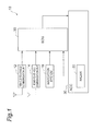
Fig. 1 is a block diagram showing the configuration of a vehicle control device according to an embodiment. -
Fig. 2 is a flowchart showing the operation of a vehicle control device according to the embodiment. -
Fig. 3 is a graph showing amplification of a deceleration due to speed reduction propagation of an ordinary vehicle. -
Fig. 4 is a graph showing prediction of absorption of speed reduction propagation according to the embodiment. -
Fig. 5 is a plan view showing a method of determining an adequate inter-vehicle distance for absorbing speed reduction propagation. -
Fig. 6 is a graph showing speed reduction propagation, amplification of a deceleration due to speed reduction propagation, and absorption of speed reduction propagation. -
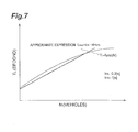
Fig. 7 is a graph showing a function of obtaining a target inter-vehicle time for which speed reduction propagation is absorbed and an approximate expression thereof. -
Fig. 8 is a side view showing a method of predicting the number of ordinary vehicles. -
Fig. 9 is a graph showing a function of obtaining a target inter-vehicle time for which speed reduction propagation is absorbed. -
Fig. 10 is a plan view showing an operation when the behavior of an ordinary vehicle is monitored. -
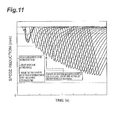
Fig. 11 is a graph showing an example where a motion of a preceding vehicle beyond the scope of the assumption is addressed. -
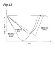
Fig. 12 is a graph showing an operation to absorb speed reduction propagation when a vehicle having the device of the embodiment mounted therein reduces speed while closing an inter-vehicle distance at a deceleration lower than a vehicle in front of an immediately preceding vehicle. -
Fig. 13 is a plan view showing an operation when information relating to speed reduction of a host vehicle is transmitted to a succeeding vehicle. -
Fig. 14 is a graph showing an operation when information relating to speed reduction of a host vehicle is transmitted to a succeeding vehicle. -
Fig. 15 is a graph showing an example where a motion of a preceding vehicle beyond the scope of the assumption is addressed. -
Fig. 16 is a graph showing a change in speed near a congestion start time due to an ordinary vehicle. -
Fig. 17 is a graph showing a change in speed near a congestion start time when speed reduction propagation is absorbed. -
Fig. 18 is a graph showing the effects of this embodiment. -
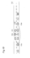
Figs. 19(A) to 19(D) are diagrams showing a process in which congestion occurs near a sag. -
Figs. 20(X) and 20(Y) are plan views showing an example where an efficient flow is produced. -
Fig. 21 is a graph showing changes in the vehicle speed of a speed-reduced vehicle, a succeeding vehicle, and a system-mounted vehicle at the time of congestion. -
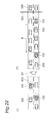
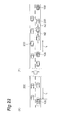
Figs. 22(X) and 22(Y) are plan views showing absorption of speed reduction propagation due to an ordinary vehicle. - Hereinafter, a vehicle control device according to an embodiment of the invention will be described with reference to the drawings. The vehicle control device of this embodiment is mounted in a vehicle, and used to perform vehicle control for improving the traffic flow on a road. As shown in
Fig. 1 , avehicle control device 10 of this embodiment includes a vehicle-to-vehicle communication unit 12, a road-to-vehicle communication unit 14, anavigation system 16, an ECU (Electronic Control Unit) 20, and an ACC (Adaptive Cruise Control) 30. - The vehicle-to-
vehicle communication unit 12 is used to transmit or receive information on the position and speed of a system-mounted vehicle other than a host vehicle or whether a vehicle control for preventing congestion is ON or OFF through vehicle-to-vehicle communication. - The road-to-
vehicle communication unit 14 is used to receive information on the traffic flow on a road, the vehicle speed of a vehicle traveling on the road, or the like from road-side facilities, such as an optical beacon communication unit. In this embodiment, the road-to-vehicle communication unit 14 may not be provided. - The
navigation system 16 includes a GPS which receives signals from a plurality of GPS (Global Positioning System) satellites by a GPS receiver and measures the position of the host vehicle from the difference between the signals, and a map information DB (Data Base) which stores map information in the host vehicle. Thenavigation system 16 is used to perform the route guidance of the host vehicle and also to acquire information relating to a place, such as a sag in front of the host vehicle, at which the reduction in the vehicle speed is caused. For example, thenavigation system 16 detects the relative position of the host vehicle with respect to the sag and outputs the relative position to theECU 20. - The
ECU 20 receives information relating to the relative position of the host vehicle with respect to the sag from thenavigation system 16 and information relating to the relative position and the relative speed of another vehicle around the host vehicle from aradar 32 of theACC 30 as input. The ECU outputs traveling control command values, such as a target vehicle speed, an acceleration G, and a target inter-vehicle distance, to theACC 30 on the basis of information input from thenavigation system 16 and theACC 30. - The
ACC 30 has aradar 32 which detects the relative position and the relative speed of another vehicle around the host vehicle. TheACC 30 performs traveling control on the basis of the traveling control command values from theECU 20 such that the host vehicle has the target vehicle speed, the acceleration G, and the target inter-vehicle distance. - Hereinafter, the operation of the
vehicle control device 10 of this embodiment will be described. First, as a premise, the reason for which congestion occurs at a sag or the like will be described. As shown inFig. 19(A) , it is assumed thatordinary vehicles 200 in which thevehicle control device 10 of this embodiment is not mounted are traveling on aroad 500 in a cascaded manner. A traffic flow increases, an inter-vehicle distance becomes close, and the vehicle speed of each of theordinary vehicles 200 is reduced by about 10 km/h. In this case, as shown in a broken-line portion of the drawing, since a vehicle which is reluctant to reduce vehicle speed makes a lane change to a passing lane, in particular, a decrease in the inter-vehicle distance in the passing lane becomes conspicuous. - As shown in
Fig. 19(B) , theordinary vehicle 200 which passes through asag 520 and inconspicuously reduces speed at an uphill section becomes a cause of congestion. Alternatively, unreasonable cutting-in of a truck or the like becomes a cause of congestion. As shown inFig. 19(C) , if the inter-vehicle distance becomes close due to the speed reduction of the precedingordinary vehicle 200, the succeedingordinary vehicle 200 reduces speed so as to maintain the inter-vehicle distance with respect to the preceding vehicle. In this case, since the succeeding vehicle should reduce speed to a speed lower than the preceding vehicle, speed reduction propagation occurs in which speed reduction propagates from the preceding vehicle to the succeeding vehicle while being amplified, thereby causing congestion. - As shown in Fig. 19(D), even after having passed through the
sag 520 causing congestion, the inter-vehicle distance between theordinary vehicles 200 becomes close, and it is difficult to increase speed. For this reason, speed recovery after speed reduction is delayed, and congestion is continued. - When producing an efficient traffic flow and guiding a vehicle to a region B where the best traffic flow is obtained, as shown in Fig. 20(X), on the
road 500 on which system-mountedvehicles 100 having thevehicle control device 10 of this embodiment mounted therein andordinary vehicles 200 are traveling in a mixed manner, the system-mountedvehicles 100 start traveling control from 5 km in front of thesag 520 such that the vehicle speed and the inter-vehicle distance become a region where the best traffic flow can be obtained. Next, as shown in Fig. 20(Y), from 1 km in front of thesag 520 to thesag 520, the vehicle speed and the inter-vehicle distance are maintained such that the best traffic flow can be obtained. Thus, as shown in a broken-line portion of the drawing, it is thought that vehicles including ordinary vehicles can belong to the region of the vehicle speed and the inter-vehicle distance where the best traffic flow can be obtained. - A method of returning a vehicle having entered a congestion region to the region of the vehicle speed and the inter-vehicle distance where the best traffic flow can be obtained is considered. As shown in
Fig. 21 , speed reduction propagation from a speed-reduced vehicle as the trigger of congestion to a first succeeding vehicle and a second succeeding vehicle is advanced while amplifying a deceleration. Accordingly, as shown in Fig. 22(X), the system-mountedvehicle 100 succeeding theordinary vehicle 200, such as a speed-reduced vehicle, causing speed reduction propagation leaves an inter-vehicle distance L, at which the speed reduction propagation is absorbable, in advance. Thus, as shown in Fig. 22(Y), even when speed reduction propagation has occurred from the preceding vehicle, the speed reduction propagation is absorbed by the inter-vehicle distance L in front of the system-mountedvehicle 100, making it possible to return a vehicle having temporarily entered the congestion region to the region of the vehicle speed and the inter-vehicle distance where the best traffic flow can be obtained. Therefore, in this embodiment, congestion is prevented by the following operation. - Hereinafter, the operation of the
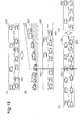
vehicle control device 10 of this embodiment will be described. As shown inFig. 2 , inter-vehicle distance control by theACC 30 is turned on (S11). When the system-mountedvehicle 100 travels through a section before and after thesag 520, and it is the time zone in which the traffic flow increases (S12), theECU 20 predicts amplification of speed reduction propagation due to theordinary vehicle 200 immediately in front of the system-mountedvehicle 100, and sets an appropriate inter-vehicle time with respect to the immediately preceding ordinary vehicle 200 (S13). When the deceleration of the immediately precedingordinary vehicle 200 is equal to or higher than a threshold value (S 14), theECU 20 allows theACC 30 to perform traveling control in a speed reduction propagation absorption mode for absorbing speed reduction propagation (S15). When the deceleration of the immediately precedingordinary vehicle 200 is lower than the threshold value (S 14), theECU 20 allows theACC 30 to perform traveling control in a preceding vehicle follow-up mode for traveling to follow the normal preceding vehicle (S 16). - As shown in
Fig. 3 , the degree of amplification of a deceleration per vehicle in the speed reduction propagation can be calculated by a simulation or the like. For example, it is assumed that the system-mountedvehicle 100 succeeds eight vehicles, and is the ninth vehicle from the lead vehicle. In this case, the degree of amplification of a deceleration for eight vehicles can be estimated from the graph ofFig. 3 . For this reason, if it is found how many vehicles are traveling in front of the system-mountedvehicle 100, it is possible to determine the degree of amplification of a deceleration as a whole. - For example, when the first vehicle is a system-mounted
vehicle 100a, the second to eighth vehicles areordinary vehicles 200, and the ninth vehicle is a system-mountedvehicle 100b, the prediction of the inter-vehicle distance for absorbing speed reduction propagation can be estimated as shown inFig. 4 . In this way, with the pre-simulation, it is possible to predict a necessary inter-vehicle distance or minimum speed by how manyordinary vehicles 200 are between the system-mountedvehicles - Hereinafter, a method of determining an appropriate inter-vehicle distance capable of absorbing speed reduction propagation will be described. As shown in
Fig. 5 , it is assumed that, on aroad 500 on which an uphill 502 is continued, the system-mountedvehicle 100a is in the lead, severalordinary vehicles 200 succeed the system-mountedvehicle 100a, and the system-mountedvehicle 100b is at the end. Let the inter-vehicle distance between the system-mountedvehicles ordinary vehicles 200 between the system-mountedvehicles vehicle 100a be Vp [km/h], and the average inter-vehicle time of theordinary vehicles 200 be TN, for example, 1.8 seconds. - In this case, the number of
ordinary vehicles 200 between the preceding system-mountedvehicle 100a and the last system-mountedvehicle 100b is predicted, and the target inter-vehicle time TL [seconds] according to the number ofordinary vehicles 200 is determined. Thus, as shown inFig. 6 , it is possible to absorb speed reduction propagation due to the precedingordinary vehicles 200. - Here, N=(Lc-L)/(TN·Vp) and TL=func(N) can be established. TL=func(N) is the function of TL with respect to N shown in
Fig. 7 , and can be approximated to, for example, func(N)=kTL·N+kT0. Here, KTL, and kT0 can be determined in advance by a simulation, and can be, for example, kTL=0.2 [seconds] and kT0=1 [second]. - When the penetration of the system-mounted
vehicle 100 is slightly smaller than theordinary vehicle 200, as shown inFig. 8 , a road-side fixedcamera 700 is installed at thesag 520, at which congestion occurs, to measure a traffic density ND [vehicles/km]. The traffic density ND measured by the road-side camera 700 is transferred to the system-mountedvehicle 100 traveling several km from thesag 520 through an opticalbeacon communication unit 600 of the road facility. The system-mountedvehicle 100 to which the traffic density ND is transferred calculates the target inter-vehicle time TL by mapping the function of the target inter-vehicle time TL [seconds] to the traffic density ND shown inFig. 9 obtained by the simulation in advance, and sets a target inter-vehicle distance L. - Alternatively, when setting an inter-vehicle distance necessary for absorbing speed reduction propagation, the system-mounted
vehicle 100 may monitor the behavior of theordinary vehicle 200, may transfer the speed reduction start position and the deceleration of the preceding vehicle to the succeeding system-mountedvehicle 100, may set an appropriate inter-vehicle distance, and may request rapid speed reduction. - As shown in
Fig. 10 , a system-mountedvehicle 100a traveling in front of anordinary vehicle 200 and a system-mountedvehicle 100c traveling laterally to theordinary vehicle 200 monitor the behavior of theordinary vehicle 200 using a radar (millimeter-wave radar or laser radar) 32, which is a surrounding recognition sensor of an autonomous system, an image recognition camera, or the like. With regard to the behavior of theordinary vehicle 200, the speed reduction start position, the deceleration, the minimum speed, and the like are used. The system-mountedvehicles ordinary vehicle 200 to the succeeding system-mountedvehicle 100b using the vehicle-to-vehicle communication unit 12. - The assumed number of
ordinary vehicles 200 between the preceding system-mountedvehicle 100a and the last system-mountedvehicle 100b changes from the difference between the conditions assumed by the above-described pre-simulation and the conditions obtained by the above-described monitoring, thereby changing the necessary inter-vehicle distance L to be adjusted to the actual situation. - A case where a preceding vehicle is beyond the scope of the assumption from the pre-simulation will be described. In this case, for example, as shown in
Fig. 11 , when the secondordinary vehicle 200 reduces speed beyond expectation and then reduces speed to be the same as the predicted third vehicle, even though sevenordinary vehicles 200 are actually traveling in front of the system-mountedvehicle 100, theECU 20 of the system-mountedvehicle 100 corrects the inter-vehicle time and changes the necessary inter-vehicle distance L assuming that eightordinary vehicles 200, one more than the seven vehicles, are traveling in front. - Hereinafter, a basic way of thinking about the absorption of the speed reduction propagation will be described. As shown in
Fig. 12 , in this embodiment, the system-mountedvehicle 100 reduces speed at a deceleration lower than the immediately preceding vehicle while closing the inter-vehicle distance from the preceding vehicle. The system-mountedvehicle 100 generates a low deceleration αt by multiplying a given ratio k to a deceleration αpre of the immediately preceding vehicle. The deceleration αt can be αt=k·αpre (0<k<1). - Control parameters for absorbing speed reduction propagation are determined taking into consideration the following items in principle.
- (1) minimum speed at the time of speed reduction: immediately preceding vehicle<immediately succeeding vehicle<system-mounted vehicle
- (2) minimum inter-vehicle distance at the time of speed reduction propagation absorption: 1.3 [seconds], which is the same as the ACC shortest inter-vehicle time
- (3) maximum relative speed with respect to the immediately preceding vehicle is equal to or lower than a threshold value: threshold value is 30 km/h or is set in accordance with the humanly allowable range
- (4) maximum deceleration: lower than the immediately preceding vehicle
- When the deceleration of the preceding vehicle is high, as shown in
Fig. 13 , the system-mountedvehicle 100b may predict the deceleration and the minimum speed of the host vehicle, and may transmit the deceleration and the minimum speed to the succeeding system-mountedvehicle 100c by the vehicle-to-vehicle communication unit 12, thereby requesting the succeeding system-mountedvehicle 100c to set an appropriate inter-vehicle distance and to perform rapid speed reduction. In this case, the deceleration and the minimum speed of the system-mountedvehicle 100b can be predicted as shown inFig. 14 . - When the system-mounted
vehicle 100b reduces speed unexpectedly, for example, as shown inFig. 15 , reduces speed to be the same as the predicted third vehicle, even though seven vehicles are actually traveling in front, the succeeding system-mountedvehicle 100c corrects the inter-vehicle time assuming that ten vehicles, three more than the seven vehicles, are traveling in front. - In this embodiment described above, on the basis of the prediction information of the speed reduction propagation when the preceding vehicle in front of the host vehicle reduces speed, such that other vehicles between the preceding vehicle and the system-mounted
vehicle 100 successively reduces speed, and the system-mountedvehicle 100 then reduces speed, theECU 20 and theACC 30 control the traveling of the system-mountedvehicle 100 such that the system-mountedvehicle 100 and theordinary vehicle 200 immediately in front of the system-mountedvehicle 100 have a predetermined relative positional relationship. Therefore, it is possible to suppress the speed reduction propagation between the preceding vehicle and the system-mountedvehicle 100 in advance, making it possible to more effectively suppress congestion. - In particular, in this embodiment, the information relating to the speed reduction of the preceding vehicle can be received from the system-mounted
vehicle 100a serving as the preceding vehicle by the vehicle-to-vehicle communication unit 12. Therefore, it is possible to know the movement of the preceding vehicle before the speed reduction propagation occurs, and with the cooperation of the system-mountedvehicle 100a serving as the preceding vehicle and the system-mountedvehicle 100b serving as the host vehicle, it becomes possible to more effectively suppress congestion. - According to this embodiment, on the basis of the deceleration of other vehicle between the preceding vehicle and the system-mounted
vehicle 100, theECU 20 and theACC 30 perform switching from control such that the preceding vehicle and the system-mountedvehicle 100 have the predetermined relative positional relationship to control such that the inter-vehicle distance from another vehicle immediately in front of the system-mountedvehicle 100 is maintained at a predetermined distance. Therefore, when theordinary vehicle 200 traveling immediately in front reduces speed beyond the scope of the assumption, it is possible to appropriately maintain the inter-vehicle distance. - According to this embodiment, when the speed reduction of the preceding vehicle is detected, the
ECU 20 and theACC 30 control the traveling of the system-mountedvehicle 100 such that the system-mountedvehicle 100 reduces speed at a deceleration lower than the preceding vehicle. Therefore, it is possible to absorb the speed reduction propagation between the preceding vehicle and the system-mountedvehicle 100, making it possible to more effectively suppress congestion. - According to this embodiment, the information relating to the speed reduction of the host vehicle can be transmitted to the succeeding vehicle behind the host vehicle by the vehicle-to-
vehicle communication unit 12. Therefore, the succeeding vehicle uses the information relating to the speed reduction of the host vehicle, thereby more effectively suppressing the occurrence of congestion due to the speed reduction propagation. - According to the vehicle control device of this embodiment described above, the device of this embodiment improves the minimum speed which decreases due to speed reduction propagation such that there is a form of the speed reduction propagation at the same congestion start time in the ordinary vehicle shown in
Fig. 16 and the system-mounted vehicle shown inFig. 17 , making it possible to suppress a decrease in speed. That is, according to this embodiment, it becomes possible to delay the congestion start time. - According to this embodiment, as shown in
Fig. 18 , the range of change in speed or the number of times of stopping decreases during congestion as well as at the time of the start of congestion. - Although the embodiment of the invention has been described, the invention is not limited to the foregoing embodiment, and various modifications may be made. For example, although in the foregoing embodiment, description has been provided focusing on a form in which a vehicle control device mounted in an individual system-mounted vehicle performs vehicle control so as to prevent congestion, for example, a vehicle control device may be disposed only in a management center, and a command from the management center may be transmitted to an individual vehicle by communication, thereby performing vehicle control so as to prevent congestion.
- According to the invention, even when the number of system-mounted vehicles in which the vehicle control device of the invention is mounted is not great, it becomes possible to more effectively suppress congestion.
-
- 10: vehicle control device
- 12: vehicle-to-vehicle communication unit
- 14: road-to-vehicle communication unit
- 16: navigation system
- 20: ECU
- 30: ACC
- 32: radar
- 100, 100a, 100b, 100c: system-mounted vehicle
- 200: ordinary vehicle
- 500: road
- 501: downhill
- 502: uphill
- 520: sag
- 600: optical beacon communication unit
- 700: road-side fixed camera
Claims (15)
- A vehicle control device comprising:information acquisition means for acquiring prediction information of speed reduction propagation when a preceding vehicle in front of a host vehicle reduces speed, such that other vehicles between the preceding vehicle and the host vehicle successively reduces speed, and the host vehicle then reduces speed; andtraveling control means for controlling the traveling of the host vehicle on the basis of the prediction information acquired by the information acquisition means such that the host vehicle and another vehicle traveling immediately in front of the host vehicle have a predetermined relative positional relationship.
- The vehicle control device according to claim 1, further comprising:receiving means for receiving information relating to the speed reduction of the preceding vehicle from the preceding vehicle.
- The vehicle control device according to claim 1 or 2,
wherein, on the basis of the deceleration of other vehicles between the preceding vehicle and the host vehicle, the traveling control means performs switching from control such that the host vehicle and another vehicle traveling immediately in front of the host vehicle have the predetermined relative positional relationship to control such that the inter-vehicle distance from another vehicle immediately in front of the host vehicle is maintained at a predetermined distance. - The vehicle control device according to any one of claims 1 to 3,
wherein, when the speed reduction of the preceding vehicle is detected, the traveling control means controls the traveling of the host vehicle such that the host vehicle reduces speed at a deceleration lower than the preceding vehicle. - The vehicle control device according to claim 4, further comprising:transmitting means for transmitting information relating to the speed reduction of the host vehicle to a succeeding vehicle behind the host vehicle.
- A vehicle control method comprising the steps of:acquiring prediction information of speed reduction propagation when a preceding vehicle in front of a host vehicle reduces speed, such that other vehicles between the preceding vehicle and the host vehicle successively reduces speed, and the host vehicle then reduces speed; andcontrolling the traveling of the host vehicle on the basis of the prediction information acquired in the step of acquiring the prediction information of the speed reduction propagation such that the host vehicle and another vehicle traveling immediately in front of the host vehicle have a predetermined relative positional relationship.
- The vehicle control method according to claim 6, further comprising the step of:receiving information relating to the speed reduction of the preceding vehicle from the preceding vehicle.
- The vehicle control method according to claim 6 or 7,
wherein, in the step of controlling the traveling of the host vehicle, switching is performed on the basis of the deceleration of other vehicles between the preceding vehicle and the host vehicle from control such that the host vehicle and another vehicle traveling immediately in front of the host vehicle have the predetermined relative positional relationship to control such that the inter-vehicle distance from another vehicle immediately in front of the host vehicle is maintained at a predetermined distance. - The vehicle control method according to any one of claims 1 to 3,
wherein, in the step of controlling the traveling of the host vehicle, when the speed reduction of the preceding vehicle is detected, the traveling of the host vehicle is controlled such that the host vehicle reduces speed at a deceleration lower than the preceding vehicle. - The vehicle control method according to claim 9, further comprising the step of:transmitting information relating to the speed reduction of the host vehicle to a succeeding vehicle behind the host vehicle.
- A vehicle control system comprising:information acquisition means for acquiring prediction information of speed reduction propagation when a preceding vehicle in front of a vehicle reduces speed, such that other vehicles between the preceding vehicle and the vehicle successively reduces speed, and the vehicle then reduces speed; andtraveling control means for controlling the traveling of the vehicle on the basis of the prediction information acquired by the information acquisition means such that the vehicle and another vehicle traveling immediately in front of the vehicle have a predetermined relative positional relationship.
- The vehicle control system according to claim 11, further comprising:receiving means for receiving information relating to the speed reduction of the preceding vehicle from the preceding vehicle.
- The vehicle control system according to claim 11 or 12,
wherein, on the basis of the deceleration of other vehicles between the preceding vehicle and the vehicle, the traveling control means performs switching from control such that the vehicle and another vehicle traveling immediately in front of the vehicle have the predetermined relative positional relationship to control such that the inter-vehicle distance from another vehicle immediately in front of the vehicle is maintained at a predetermined distance. - The vehicle control system according to any one of claims 11 to 13,
wherein, when the speed reduction of the preceding vehicle is detected, the traveling control means controls the traveling of the vehicle such that the vehicle reduces speed at a deceleration lower than the preceding vehicle. - The vehicle control system according to claim 14, further comprising:transmitting means for transmitting information relating to the speed reduction of the vehicle to a succeeding vehicle behind the vehicle.
Applications Claiming Priority (1)
| Application Number | Priority Date | Filing Date | Title |
|---|---|---|---|
| PCT/JP2009/063428 WO2011013203A1 (en) | 2009-07-28 | 2009-07-28 | Vehicle control device, vehicle control method, and vehicle control system |
Publications (2)
| Publication Number | Publication Date |
|---|---|
| EP2461304A1 true EP2461304A1 (en) | 2012-06-06 |
| EP2461304A4 EP2461304A4 (en) | 2013-02-27 |
Family
ID=43528880
Family Applications (1)
| Application Number | Title | Priority Date | Filing Date |
|---|---|---|---|
| EP09847795A Ceased EP2461304A4 (en) | 2009-07-28 | 2009-07-28 | DEVICE, METHOD AND CONTROL SYSTEM FOR VEHICLE |
Country Status (5)
| Country | Link |
|---|---|
| US (1) | US9174643B2 (en) |
| EP (1) | EP2461304A4 (en) |
| JP (1) | JP5273250B2 (en) |
| CN (1) | CN102470870B (en) |
| WO (1) | WO2011013203A1 (en) |
Cited By (2)
| Publication number | Priority date | Publication date | Assignee | Title |
|---|---|---|---|---|
| US9183745B2 (en) | 2013-07-11 | 2015-11-10 | Man Truck & Bus Ag | Method for regulating the distance of a vehicle from a preceding vehicle |
| EP2688054A4 (en) * | 2011-03-18 | 2015-12-02 | Toyota Motor Co Ltd | DRIVING AIDS APPARATUS AND INFORMATION PROCESSING APPARATUS FOR VEHICLES |
Families Citing this family (73)
| Publication number | Priority date | Publication date | Assignee | Title |
|---|---|---|---|---|
| CN102473350B (en) | 2009-07-27 | 2014-04-16 | 丰田自动车株式会社 | Vehicular information processing device |
| US9174643B2 (en) | 2009-07-28 | 2015-11-03 | Toyota Jidosha Kabushiki Kaisha | Vehicle control device, vehicle control method, and vehicle control system |
| EP2876621A1 (en) | 2009-07-28 | 2015-05-27 | Toyota Jidosha Kabushiki Kaisha | Vehicle control device, vehicle control method, and vehicle control system |
| WO2011013216A1 (en) | 2009-07-29 | 2011-02-03 | トヨタ自動車株式会社 | Vehicle controller, control method for vehicle and control system for vehicle |
| JP5668359B2 (en) * | 2010-08-11 | 2015-02-12 | トヨタ自動車株式会社 | Vehicle control device |
| JP5617703B2 (en) * | 2011-03-09 | 2014-11-05 | トヨタ自動車株式会社 | Driving assistance device |
| JP6069867B2 (en) * | 2012-03-28 | 2017-02-01 | 富士通株式会社 | Running condition management method and running situation management apparatus |
| SE536818C2 (en) * | 2012-03-29 | 2014-09-23 | Scania Cv Ab | Procedure and system for distance adjustment during travel widened vehicle train |
| JP6055848B2 (en) * | 2013-02-01 | 2016-12-27 | 日立オートモティブシステムズ株式会社 | Travel control device and travel control system |
| US9828011B2 (en) * | 2013-12-18 | 2017-11-28 | Thales Canada Inc | Communication system for guideway mounted vehicle and method of using the same |
| JP6326983B2 (en) * | 2014-06-03 | 2018-05-23 | 日産自動車株式会社 | Driving support system and driving support method |
| DE102014218198A1 (en) * | 2014-09-11 | 2016-03-17 | Robert Bosch Gmbh | Distance control system for motor vehicles |
| US10332403B2 (en) * | 2017-01-04 | 2019-06-25 | Honda Motor Co., Ltd. | System and method for vehicle congestion estimation |
| CN106444733B (en) * | 2016-06-27 | 2021-07-16 | 联想(北京)有限公司 | An information processing method and electronic device |
| US9928746B1 (en) | 2016-09-16 | 2018-03-27 | Ford Global Technologies, Llc | Vehicle-to-vehicle cooperation to marshal traffic |
| JP6414166B2 (en) * | 2016-09-20 | 2018-10-31 | トヨタ自動車株式会社 | Vehicle travel control device |
| CN111886169B (en) * | 2018-03-27 | 2024-05-10 | 日产自动车株式会社 | Control method and control device for automatic driving vehicle |
| CN111361558B (en) * | 2018-12-25 | 2022-12-23 | 富泰华工业(深圳)有限公司 | Vehicle and vehicle automatic deceleration method |
| EP3790295B1 (en) * | 2019-09-09 | 2024-05-29 | Volkswagen AG | Method, computer program, and apparatus for determining a minimum inter-vehicular distance for a platoon, vehicle, traffic control entity |
| JP7215383B2 (en) | 2019-09-20 | 2023-01-31 | トヨタ自動車株式会社 | Vehicle pedal device |
| JP7456428B2 (en) | 2021-09-27 | 2024-03-27 | トヨタ自動車株式会社 | Vehicle speed limiting device, vehicle speed limiting method, and vehicle |
| JP7697338B2 (en) * | 2021-09-28 | 2025-06-24 | 沖電気工業株式会社 | Traffic flow control device, traffic flow control method and program |
| JP7505467B2 (en) | 2021-09-28 | 2024-06-25 | トヨタ自動車株式会社 | Driving assistance device, driving assistance method, and program |
| JP2023069305A (en) | 2021-11-05 | 2023-05-18 | トヨタ自動車株式会社 | Vehicle driving support device, vehicle driving support method, and program |
| JP7494830B2 (en) | 2021-11-10 | 2024-06-04 | トヨタ自動車株式会社 | Vehicle driving support device, vehicle driving support method, vehicle driving support program, and vehicle equipped with vehicle driving support device |
| JP7521517B2 (en) | 2021-12-20 | 2024-07-24 | トヨタ自動車株式会社 | VEHICLE CONTROL DEVICE, VEHICLE, ACCELERATION/DECELERATION CONTROL METHOD, AND VEHICLE CONTROL PROGRAM |
| JP7444156B2 (en) | 2021-12-22 | 2024-03-06 | トヨタ自動車株式会社 | Driving support devices, vehicles, driving support methods, and driving support programs |
| JP7528918B2 (en) | 2021-12-24 | 2024-08-06 | トヨタ自動車株式会社 | Deceleration support device, vehicle, deceleration support method, and program |
| JP7498438B2 (en) | 2022-01-20 | 2024-06-12 | トヨタ自動車株式会社 | Driving assistance device, vehicle, driving assistance method, and driving assistance program |
| JP7601017B2 (en) | 2022-01-27 | 2024-12-17 | トヨタ自動車株式会社 | Vehicle Driving Assistance Device |
| JP7509160B2 (en) | 2022-03-17 | 2024-07-02 | トヨタ自動車株式会社 | Vehicle speed limiting device, vehicle speed limiting method, and vehicle speed limiting program |
| JP7824574B2 (en) | 2022-03-24 | 2026-03-05 | トヨタ自動車株式会社 | Driving assistance device, driving assistance method, and program |
| JP7622689B2 (en) | 2022-04-05 | 2025-01-28 | トヨタ自動車株式会社 | Driving assistance device, driving assistance method, and driving assistance program |
| JP7709126B2 (en) * | 2022-06-30 | 2025-07-16 | トヨタ自動車株式会社 | Control device, control method, and program |
| JP7687294B2 (en) | 2022-07-14 | 2025-06-03 | トヨタ自動車株式会社 | Driving Support Devices |
| JP2024024266A (en) | 2022-08-09 | 2024-02-22 | トヨタ自動車株式会社 | Driving support device |
| JP7722295B2 (en) | 2022-08-09 | 2025-08-13 | トヨタ自動車株式会社 | Driving assistance devices |
| JP7726152B2 (en) | 2022-08-09 | 2025-08-20 | トヨタ自動車株式会社 | Driving assistance devices |
| JP2024034044A (en) | 2022-08-31 | 2024-03-13 | トヨタ自動車株式会社 | Driving support device, driving support method, and driving support program |
| JP7663087B2 (en) | 2022-09-05 | 2025-04-16 | トヨタ自動車株式会社 | Vehicle deceleration support device, vehicle deceleration support method, and vehicle deceleration support program |
| JP7663088B2 (en) | 2022-09-05 | 2025-04-16 | トヨタ自動車株式会社 | Vehicle deceleration support device, vehicle deceleration support method, and vehicle deceleration support program |
| JP7715114B2 (en) | 2022-09-29 | 2025-07-30 | トヨタ自動車株式会社 | Driving assistance devices |
| JP7650422B2 (en) | 2022-10-12 | 2025-03-25 | トヨタ自動車株式会社 | Apparatus, method, and program for detecting deceleration of a preceding vehicle |
| JP2024057861A (en) | 2022-10-13 | 2024-04-25 | トヨタ自動車株式会社 | Vehicle running device |
| JP7746960B2 (en) | 2022-10-14 | 2025-10-01 | トヨタ自動車株式会社 | Driving assistance devices |
| JP7754050B2 (en) | 2022-10-25 | 2025-10-15 | トヨタ自動車株式会社 | Driving assistance devices |
| JP2024066082A (en) | 2022-11-01 | 2024-05-15 | トヨタ自動車株式会社 | Vehicle deceleration support device |
| JP7760986B2 (en) | 2022-11-01 | 2025-10-28 | トヨタ自動車株式会社 | Driving assistance device and processing method for driving assistance device |
| JP7845166B2 (en) | 2022-12-09 | 2026-04-14 | トヨタ自動車株式会社 | Driving assistance systems |
| JP7775813B2 (en) | 2022-12-09 | 2025-11-26 | トヨタ自動車株式会社 | Map Management Device |
| JP2024082833A (en) | 2022-12-09 | 2024-06-20 | トヨタ自動車株式会社 | Driving Support Devices |
| JP7722346B2 (en) | 2022-12-14 | 2025-08-13 | トヨタ自動車株式会社 | Vehicle control device |
| JP7746978B2 (en) | 2022-12-14 | 2025-10-01 | トヨタ自動車株式会社 | Vehicle control device |
| JP2024086127A (en) | 2022-12-16 | 2024-06-27 | トヨタ自動車株式会社 | Display Control Device |
| JP7708086B2 (en) | 2022-12-21 | 2025-07-15 | トヨタ自動車株式会社 | Vehicle control device |
| JP7835158B2 (en) | 2022-12-28 | 2026-03-25 | トヨタ自動車株式会社 | Lighting status recognition device |
| JP7754082B2 (en) | 2022-12-28 | 2025-10-15 | トヨタ自動車株式会社 | Vehicle control device |
| JP7831326B2 (en) | 2023-01-13 | 2026-03-17 | トヨタ自動車株式会社 | Vehicle control system |
| JP7768153B2 (en) | 2023-01-13 | 2025-11-12 | トヨタ自動車株式会社 | Vehicle stop-holding device |
| JP7768152B2 (en) | 2023-01-13 | 2025-11-12 | トヨタ自動車株式会社 | Vehicle stop device |
| JP7824577B2 (en) | 2023-02-03 | 2026-03-05 | トヨタ自動車株式会社 | Vehicle control device |
| JP7769308B2 (en) | 2023-02-10 | 2025-11-13 | トヨタ自動車株式会社 | Driving assistance device, driving assistance method, and driving assistance program |
| JP2024124667A (en) | 2023-03-03 | 2024-09-13 | トヨタ自動車株式会社 | Vehicle driving assistance device and vehicle driving assistance method |
| JP2024127578A (en) | 2023-03-09 | 2024-09-20 | トヨタ自動車株式会社 | Driving Support Devices |
| JP7740289B2 (en) | 2023-03-24 | 2025-09-17 | トヨタ自動車株式会社 | Vehicle driving assistance device |
| JP7831368B2 (en) | 2023-03-24 | 2026-03-17 | トヨタ自動車株式会社 | Vehicle driving assistance system |
| JP7747015B2 (en) | 2023-04-07 | 2025-10-01 | トヨタ自動車株式会社 | Vehicle control device |
| JP2025018293A (en) | 2023-07-26 | 2025-02-06 | トヨタ自動車株式会社 | Vehicle equipped with a vehicle control device |
| JP7831444B2 (en) | 2023-08-17 | 2026-03-17 | トヨタ自動車株式会社 | car |
| JP7845317B2 (en) | 2023-09-05 | 2026-04-14 | トヨタ自動車株式会社 | Driving assistance systems |
| JP2025068665A (en) | 2023-10-17 | 2025-04-30 | トヨタ自動車株式会社 | Driving assistance device and driving assistance method |
| JP2025068830A (en) | 2023-10-17 | 2025-04-30 | トヨタ自動車株式会社 | Vehicle travel support device |
| JP2025130218A (en) | 2024-02-27 | 2025-09-08 | トヨタ自動車株式会社 | Vehicle control device |
Family Cites Families (23)
| Publication number | Priority date | Publication date | Assignee | Title |
|---|---|---|---|---|
| US5134393A (en) | 1990-04-02 | 1992-07-28 | Henson H Keith | Traffic control system |
| JP3732292B2 (en) * | 1996-11-27 | 2006-01-05 | 本田技研工業株式会社 | Vehicle group running control system |
| US20020150050A1 (en) | 1999-06-17 | 2002-10-17 | Nathanson Martin D. | Automotive telemetry protocol |
| JPH11250396A (en) | 1998-02-27 | 1999-09-17 | Hitachi Ltd | Vehicle position information display apparatus and method |
| DE10034723C2 (en) * | 2000-07-17 | 2003-01-02 | Friedrich-Karl Wefelmeier | Deceleration system for motor vehicles |
| JP3777970B2 (en) | 2000-11-02 | 2006-05-24 | 日産自動車株式会社 | Preceding vehicle tracking control device |
| US6711280B2 (en) | 2001-05-25 | 2004-03-23 | Oscar M. Stafsudd | Method and apparatus for intelligent ranging via image subtraction |
| JP3832380B2 (en) * | 2002-04-25 | 2006-10-11 | 株式会社日立製作所 | Automatic vehicle speed control device |
| US6882923B2 (en) | 2002-10-17 | 2005-04-19 | Ford Global Technologies, Llc | Adaptive cruise control system using shared vehicle network data |
| US6813561B2 (en) | 2003-03-25 | 2004-11-02 | Ford Global Technologies, Llc | Relative positioning for vehicles using GPS enhanced with bluetooth range finding |
| US7554982B2 (en) | 2003-05-16 | 2009-06-30 | Oki Electric Industry Co., Ltd. | Communication terminal and communication network |
| JP4127403B2 (en) | 2005-02-28 | 2008-07-30 | 独立行政法人 宇宙航空研究開発機構 | Method and apparatus for stabilizing control of vehicle traffic |
| JP4912007B2 (en) | 2005-03-28 | 2012-04-04 | 株式会社Ihi | Traffic jam mitigation device and method |
| US7454288B2 (en) | 2005-07-29 | 2008-11-18 | Gm Global Technology Operations, Inc. | System and method for clustering probe vehicles for real-time traffic application |
| JP4710529B2 (en) | 2005-10-05 | 2011-06-29 | 日産自動車株式会社 | Travel control device |
| US20070083318A1 (en) | 2005-10-07 | 2007-04-12 | Parikh Jayendra S | Adaptive cruise control using vehicle-to-vehicle wireless communication |
| JP4765842B2 (en) | 2006-08-29 | 2011-09-07 | トヨタ自動車株式会社 | Vehicle group control system |
| JP4806618B2 (en) | 2006-10-02 | 2011-11-02 | ルネサスエレクトロニクス株式会社 | In-vehicle control device and congestion relief support method |
| JP2008094167A (en) | 2006-10-06 | 2008-04-24 | Toyota Motor Corp | Travel control support system, travel control device and travel stability determination device constituting the system |
| JP4946542B2 (en) | 2007-03-14 | 2012-06-06 | アイシン・エィ・ダブリュ株式会社 | Traffic jam prevention device and traffic jam prevention method |
| JP2008232391A (en) | 2007-03-23 | 2008-10-02 | Toyota Motor Corp | Automatic transmission control system |
| EP2876621A1 (en) | 2009-07-28 | 2015-05-27 | Toyota Jidosha Kabushiki Kaisha | Vehicle control device, vehicle control method, and vehicle control system |
| US9174643B2 (en) | 2009-07-28 | 2015-11-03 | Toyota Jidosha Kabushiki Kaisha | Vehicle control device, vehicle control method, and vehicle control system |
-
2009
- 2009-07-28 US US13/387,306 patent/US9174643B2/en active Active
- 2009-07-28 WO PCT/JP2009/063428 patent/WO2011013203A1/en not_active Ceased
- 2009-07-28 JP JP2011524565A patent/JP5273250B2/en active Active
- 2009-07-28 EP EP09847795A patent/EP2461304A4/en not_active Ceased
- 2009-07-28 CN CN200980160613.9A patent/CN102470870B/en active Active
Cited By (2)
| Publication number | Priority date | Publication date | Assignee | Title |
|---|---|---|---|---|
| EP2688054A4 (en) * | 2011-03-18 | 2015-12-02 | Toyota Motor Co Ltd | DRIVING AIDS APPARATUS AND INFORMATION PROCESSING APPARATUS FOR VEHICLES |
| US9183745B2 (en) | 2013-07-11 | 2015-11-10 | Man Truck & Bus Ag | Method for regulating the distance of a vehicle from a preceding vehicle |
Also Published As
| Publication number | Publication date |
|---|---|
| US9174643B2 (en) | 2015-11-03 |
| JPWO2011013203A1 (en) | 2013-01-07 |
| WO2011013203A1 (en) | 2011-02-03 |
| US20120166059A1 (en) | 2012-06-28 |
| CN102470870A (en) | 2012-05-23 |
| JP5273250B2 (en) | 2013-08-28 |
| EP2461304A4 (en) | 2013-02-27 |
| CN102470870B (en) | 2015-04-22 |
Similar Documents
| Publication | Publication Date | Title |
|---|---|---|
| US9174643B2 (en) | Vehicle control device, vehicle control method, and vehicle control system | |
| US11565722B2 (en) | Vehicle trajectory prediction near or at traffic signal | |
| EP3683782B1 (en) | Method for assisting a driver, driver assistance system, and vehicle including such driver assistance system | |
| US8781707B2 (en) | Vehicle control device, vehicle control method, and vehicle control system | |
| US8972080B2 (en) | Traffic control system, vehicle control system, traffic regulation system, and traffic control method | |
| EP2460706B1 (en) | Vehicle control device, vehicle control method, and vehicle control system | |
| US8185296B2 (en) | Driving assisting apparatus and driving assisting method | |
| US11247682B2 (en) | Vehicle control system, vehicle control method, and vehicle control program | |
| CN102473346B (en) | Vehicle control device, vehicle control method, and vehicle control system | |
| US20130030688A1 (en) | Vehicle driving assistance device | |
| US11830364B2 (en) | Driving assist method and driving assist device | |
| US8676486B2 (en) | Vehicular information processing device | |
| US20200189596A1 (en) | Apparatus and method for controlling running of vehicle | |
| KR20090113309A (en) | Inter-vehicle communication system and how to display speed and deceleration | |
| US11221226B2 (en) | Passing gate determining device, vehicle control system, passing gate determining method, and storage medium | |
| JP2016051467A (en) | Method and system for using wide-area scene context for adaptation prediction and corresponding program, vehicle equipped with the system | |
| WO2015047179A1 (en) | Control unit and method to control a vehicle in a vehicle platoon based on the predicted behaviour of the preceeding vehicle | |
| CN108364486B (en) | Multi-scene vehicle priority self-adaptive traffic signal control system and working method thereof | |
| CN114115215B (en) | Platoon driving control method and system | |
| US20190144002A1 (en) | Autonomous driving system, non-transitory tangible computer readable medium, and autonomous driving state notifying method | |
| US20230154333A1 (en) | Route prediction device, route prediction method, and vehicle control system | |
| JP2012081924A (en) | Driving support device | |
| JP2021068315A (en) | Estimation method and estimation system of lane condition | |
| JP4867479B2 (en) | Vehicle deceleration determination system, signal control device, in-vehicle device, signal control method, vehicle deceleration determination method, and computer program | |
| JP2011028639A (en) | Vehicle control system |
Legal Events
| Date | Code | Title | Description |
|---|---|---|---|
| PUAI | Public reference made under article 153(3) epc to a published international application that has entered the european phase |
Free format text: ORIGINAL CODE: 0009012 |
|
| 17P | Request for examination filed |
Effective date: 20120213 |
|
| AK | Designated contracting states |
Kind code of ref document: A1 Designated state(s): AT BE BG CH CY CZ DE DK EE ES FI FR GB GR HR HU IE IS IT LI LT LU LV MC MK MT NL NO PL PT RO SE SI SK SM TR |
|
| DAX | Request for extension of the european patent (deleted) | ||
| A4 | Supplementary search report drawn up and despatched |
Effective date: 20130124 |
|
| RAP1 | Party data changed (applicant data changed or rights of an application transferred) |
Owner name: TOYOTA JIDOSHA KABUSHIKI KAISHA |
|
| RIC1 | Information provided on ipc code assigned before grant |
Ipc: B60W 30/16 20120101AFI20130118BHEP Ipc: G08G 1/16 20060101ALI20130118BHEP |
|
| STAA | Information on the status of an ep patent application or granted ep patent |
Free format text: STATUS: EXAMINATION IS IN PROGRESS |
|
| 17Q | First examination report despatched |
Effective date: 20170216 |
|
| REG | Reference to a national code |
Ref country code: DE Ref legal event code: R003 |
|
| STAA | Information on the status of an ep patent application or granted ep patent |
Free format text: STATUS: THE APPLICATION HAS BEEN REFUSED |
|
| 18R | Application refused |
Effective date: 20200324 |