EP2461227A2 - Electronic module and electronic device - Google Patents
Electronic module and electronic device Download PDFInfo
- Publication number
- EP2461227A2 EP2461227A2 EP11191292A EP11191292A EP2461227A2 EP 2461227 A2 EP2461227 A2 EP 2461227A2 EP 11191292 A EP11191292 A EP 11191292A EP 11191292 A EP11191292 A EP 11191292A EP 2461227 A2 EP2461227 A2 EP 2461227A2
- Authority
- EP
- European Patent Office
- Prior art keywords
- motherboard
- connector
- electronic device
- opening
- expansion card
- Prior art date
- Legal status (The legal status is an assumption and is not a legal conclusion. Google has not performed a legal analysis and makes no representation as to the accuracy of the status listed.)
- Withdrawn
Links
Images




Classifications
-
- G—PHYSICS
- G06—COMPUTING OR CALCULATING; COUNTING
- G06F—ELECTRIC DIGITAL DATA PROCESSING
- G06F1/00—Details not covered by groups G06F3/00 - G06F13/00 and G06F21/00
- G06F1/16—Constructional details or arrangements
- G06F1/18—Packaging or power distribution
- G06F1/183—Internal mounting support structures, e.g. for supporting printed circuit boards
- G06F1/185—Mounting of expansion boards
-
- H—ELECTRICITY
- H05—ELECTRIC TECHNIQUES NOT OTHERWISE PROVIDED FOR
- H05K—PRINTED CIRCUITS; CASINGS OR CONSTRUCTIONAL DETAILS OF ELECTRIC APPARATUS; MANUFACTURE OF ASSEMBLAGES OF ELECTRICAL COMPONENTS
- H05K1/00—Printed circuits
- H05K1/02—Details
- H05K1/14—Structural association of two or more printed circuits
- H05K1/142—Arrangements of planar printed circuit boards in the same plane, e.g. auxiliary printed circuit insert mounted in a main printed circuit
-
- H—ELECTRICITY
- H05—ELECTRIC TECHNIQUES NOT OTHERWISE PROVIDED FOR
- H05K—PRINTED CIRCUITS; CASINGS OR CONSTRUCTIONAL DETAILS OF ELECTRIC APPARATUS; MANUFACTURE OF ASSEMBLAGES OF ELECTRICAL COMPONENTS
- H05K2201/00—Indexing scheme relating to printed circuits covered by H05K1/00
- H05K2201/04—Assemblies of printed circuits
- H05K2201/048—Second PCB mounted on first PCB by inserting in window or holes of the first PCB
-
- H—ELECTRICITY
- H05—ELECTRIC TECHNIQUES NOT OTHERWISE PROVIDED FOR
- H05K—PRINTED CIRCUITS; CASINGS OR CONSTRUCTIONAL DETAILS OF ELECTRIC APPARATUS; MANUFACTURE OF ASSEMBLAGES OF ELECTRICAL COMPONENTS
- H05K2201/00—Indexing scheme relating to printed circuits covered by H05K1/00
- H05K2201/10—Details of components or other objects attached to or integrated in a printed circuit board
- H05K2201/10007—Types of components
- H05K2201/10189—Non-printed connector
-
- H—ELECTRICITY
- H05—ELECTRIC TECHNIQUES NOT OTHERWISE PROVIDED FOR
- H05K—PRINTED CIRCUITS; CASINGS OR CONSTRUCTIONAL DETAILS OF ELECTRIC APPARATUS; MANUFACTURE OF ASSEMBLAGES OF ELECTRICAL COMPONENTS
- H05K2201/00—Indexing scheme relating to printed circuits covered by H05K1/00
- H05K2201/10—Details of components or other objects attached to or integrated in a printed circuit board
- H05K2201/10431—Details of mounted components
- H05K2201/10439—Position of a single component
- H05K2201/10446—Mounted on an edge
Definitions
- the invention relates to an electronic module and, more particularly, to a structure improvement of the electronic module in an electronic device.
- a display card or a memory card is assembled (stacked) with a motherboard with the non-coplanar way, but the structure cannot meet the requirement of lighter and thinner.
- An electronic module having a motherboard, a connector and an expansion card is disclosed.
- the motherboard includes an opening.
- the connector is disposed at the motherboard and at one side of the opening.
- the expansion card is inserted to the connector at one side of the opening and coplanar with the motherboard.
- An electronic device having an electronic module having a motherboard, a connector, an expansion card and a housing.
- the motherboard includes an opening.
- the connector is disposed at the motherboard and at one side of the opening.
- the expansion card is inserted to the connector in order to be placed in the opening and coplanar with the motherboard.
- the motherboard, the connector and the expansion card are disposed in the housing.
- FIG. 1A is a schematic diagram showing partial of an electronic device in an embodiment
- FIG. 1B is a partial enlarged view showing the electronic module and electronic device in FIG. 1A ;
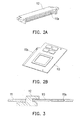
- FIG. 2A and FIG. 2B are schematic diagrams showing a part of components of the electronic module and electronic device in FIG. 1A ;
- FIG. 3 is a side view showing a partial structure of the electronic module and electronic device in FIG. 1A ;
- FIG. 4A to FIG. 4D are schematic diagrams showing electronic devices in embodiments.
- FIG. 1A is a schematic diagram showing partial of an electronic device in an embodiment.
- FIG. 1B is a partial enlarged view showing the electronic module and electronic device in FIG. 1A .
- FIG. 2A and FIG. 2B are schematic diagrams showing a part of components of the electronic module and electronic device in FIG. 1A .
- an electronic device 100 includes an electronic module 110 and a housing 120 for accommodating the electronic module 110.
- the electronic module 110 includes a motherboard 111, a connector 112 and an expansion card 113.
- the motherboard 111 includes an opening 111 which is not disposed at the edge of the motherboard 111, and the outline of the opening 111 forms a closed area, as shown in FIG. 1B .
- the connector 112 is disposed at the motherboard 111 and at one side of the opening 111 a.
- the opening 111 also may be formed at any position of the motherboard 111 by demand.
- FIG. 3 is a side view showing a partial structure of the electronic device in FIG. 1A .
- the outline of the opening 111a at the motherboard 111 matches with the outline of the expansion card 113.
- the expansion card 113 is placed in the opening 111a and coplanar with the motherboard 111. That is, the circuit board of the expansion card 113 and the circuit board of the motherboard 111 are at one plane.
- the thickness of the electronic module and electronic device is reduced. Since the expansion card 113 and the motherboard 111 are at one plane, the manufacturing process for fixing the expansion card 113 and the motherboard 111 are much easier.
- the connection of the motherboard 111, the connector 112 and the expansion card 113 is further illustrated below.
- the connector 112 may be an inclined insert connector or a flat insert connector.
- the connector 112 is disposed at one side of the opening 111a of the motherboard 111, and the connector 112 includes a slot 112a for the expansion card 113 to inclined or flat inserting in.
- One end of the expansion card 113 has an inserting part 113a for inclined inserting or flat inserting to the slot 112a of the connector 112.
- the user may insert the inserting part 113a of the expansion card 113 to the slot 112a of the connector 112 inclinedly or flatly. After insert in, the expansion card 113 is placed in the opening 111a of the motherboard 111 and coplanar with the motherboard 111.
- the motherboard 111 at least includes one fastener 111b to fix the insert-in expansion card 113 into the opening 111a.
- the fastener 111b may include fixing sheets and multiple screws for locking the fixing sheets to the motherboard 111 and the expansion card 113.
- the connector 112 may at least include a fastener to fix the expansion card 113 into the opening 111a.
- the fastener may be a latch structure of a card connector.
- the motherboard 111 of one specification may match with the expansion card 113 with different functions to meet various requirements, reduce manufacture cost, and decrease the thickness of the electronic device and electronic module.
- the expansion card 113 with different functions such as a display card or a memory card, may be selected according to personal preference.
- FIG. 4A to FIG. 4D are schematic diagrams showing electronic devices in embodiments.
- the electronic device 210 may be a notebook 200.
- the notebook 200 having a housing 220.
- the inside of the notebook 200 having an electronic module 110 as showed in FIG. 1A , and the housing 220 accommodates the electronic module 110.
- the notebook 200 further includes a display 230.
- the display 230 is disposed at the housing 220 and electrically connected to the electronic device 210.
- the housing 220 of the electronic device 210 (the notebook computer 200) includes a bottom housing 221 and an upper housing 222.
- the bottom housing 221 is pivotally connected to the upper housing 222, the bottom housing 221 accommodates the notebook 200, and the display 230 is disposed at the upper housing 222.
- the bottom housing 221 is a host part of the notebook computer
- the upper housing 222 is a display part of the notebook computer.
- the electronic device 310 may be a mini-computer system 300.
- An external independent display (not shown) may be connected with the mini-computer 300 as an image human-machine interface (HMI).
- HMI human-machine interface
- the electronic device 410 may be a table PC 400.
- the inside of the table PC 400 having an electronic module 110, as shown in in FIG. 1A , and the housing 420 accommodates the electronic module110.
- the table pc 400 further includes a display 430 disposed at the housing 420.
- the electronic device 510 may be a tablet PC 500 is disclosed.
- the tablet PC 500 having an electronic module 110, as shown in FIG. 1A and a housing 520 and the housing 520 accommodates the electronic device 510.
- the tablet PC 500 further includes a display 530 disposed at the housing 520.
- the expansion card is disposed at and coplanar with the motherboard, the electronic module and the electronic device can be thinner. Moreover, a multi-function electronic device can be modularized, and thus the expansion cards with different functions can be used in a motherboard, which meets various requirements of the users in buying or updating.
Landscapes
- Engineering & Computer Science (AREA)
- Theoretical Computer Science (AREA)
- Microelectronics & Electronic Packaging (AREA)
- Computer Hardware Design (AREA)
- Power Engineering (AREA)
- Human Computer Interaction (AREA)
- Physics & Mathematics (AREA)
- General Engineering & Computer Science (AREA)
- General Physics & Mathematics (AREA)
- Casings For Electric Apparatus (AREA)
- Mounting Of Printed Circuit Boards And The Like (AREA)
- Coupling Device And Connection With Printed Circuit (AREA)
Abstract
Description
- The invention relates to an electronic module and, more particularly, to a structure improvement of the electronic module in an electronic device.
- Various electronic products with different functions come on the market, and they are widely used in daily life and work. Electronic products, such as a desktop computer, a notebook and a tablet personal computer (PC), are usually used to deal with communication, schedule management or text processing. Benefit from the development of semiconductor elements and display technology, the electronic products become lighter, thinner, multi-functional and portable.
- In a conventional computer, a display card or a memory card is assembled (stacked) with a motherboard with the non-coplanar way, but the structure cannot meet the requirement of lighter and thinner.
- An electronic module having a motherboard, a connector and an expansion card is disclosed. The motherboard includes an opening. The connector is disposed at the motherboard and at one side of the opening. The expansion card is inserted to the connector at one side of the opening and coplanar with the motherboard.
- An electronic device having an electronic module is disclosed, the electronic device having a motherboard, a connector, an expansion card and a housing. The motherboard includes an opening. The connector is disposed at the motherboard and at one side of the opening. The expansion card is inserted to the connector in order to be placed in the opening and coplanar with the motherboard. The motherboard, the connector and the expansion card are disposed in the housing.
- These and other features, aspects and advantages of the present invention will become better understood with regard to the following description, appended claims, and accompanying drawings.
-
FIG. 1A is a schematic diagram showing partial of an electronic device in an embodiment; -
FIG. 1B is a partial enlarged view showing the electronic module and electronic device inFIG. 1A ; -
FIG. 2A and FIG. 2B are schematic diagrams showing a part of components of the electronic module and electronic device inFIG. 1A ; -
FIG. 3 is a side view showing a partial structure of the electronic module and electronic device inFIG. 1A ; and -
FIG. 4A to FIG. 4D are schematic diagrams showing electronic devices in embodiments. -
FIG. 1A is a schematic diagram showing partial of an electronic device in an embodiment.FIG. 1B is a partial enlarged view showing the electronic module and electronic device inFIG. 1A .FIG. 2A and FIG. 2B are schematic diagrams showing a part of components of the electronic module and electronic device inFIG. 1A . As showed in Figures, anelectronic device 100 includes anelectronic module 110 and ahousing 120 for accommodating theelectronic module 110. Theelectronic module 110 includes amotherboard 111, aconnector 112 and anexpansion card 113. - The
motherboard 111 includes anopening 111 which is not disposed at the edge of themotherboard 111, and the outline of the opening 111 forms a closed area, as shown inFIG. 1B . Theconnector 112 is disposed at themotherboard 111 and at one side of theopening 111 a. The opening 111 also may be formed at any position of themotherboard 111 by demand. -
FIG. 3 is a side view showing a partial structure of the electronic device inFIG. 1A . The outline of the opening 111a at themotherboard 111 matches with the outline of theexpansion card 113. In other words, after assembly, theexpansion card 113 is placed in the opening 111a and coplanar with themotherboard 111. That is, the circuit board of theexpansion card 113 and the circuit board of themotherboard 111 are at one plane. - Consequently, comparing to the thickness of conventional stacked structure, the thickness of the electronic module and electronic device is reduced. Since the
expansion card 113 and themotherboard 111 are at one plane, the manufacturing process for fixing theexpansion card 113 and themotherboard 111 are much easier. - The connection of the
motherboard 111, theconnector 112 and theexpansion card 113 is further illustrated below. Theconnector 112 may be an inclined insert connector or a flat insert connector. Theconnector 112 is disposed at one side of the opening 111a of themotherboard 111, and theconnector 112 includes aslot 112a for theexpansion card 113 to inclined or flat inserting in. One end of theexpansion card 113 has aninserting part 113a for inclined inserting or flat inserting to theslot 112a of theconnector 112. - The user may insert the
inserting part 113a of theexpansion card 113 to theslot 112a of theconnector 112 inclinedly or flatly. After insert in, theexpansion card 113 is placed in the opening 111a of themotherboard 111 and coplanar with themotherboard 111. - After the
expansion card 113 is placed in the opening 111a, the fixing method of theexpansion card 113 and themotherboard 111 is further illustrated. In an embodiment, themotherboard 111 at least includes onefastener 111b to fix the insert-inexpansion card 113 into the opening 111a. Thefastener 111b may include fixing sheets and multiple screws for locking the fixing sheets to themotherboard 111 and theexpansion card 113. - In another embodiment, the
connector 112 may at least include a fastener to fix theexpansion card 113 into theopening 111a. For example, the fastener may be a latch structure of a card connector. - The
motherboard 111 of one specification may match with theexpansion card 113 with different functions to meet various requirements, reduce manufacture cost, and decrease the thickness of the electronic device and electronic module. Moreover, theexpansion card 113 with different functions, such as a display card or a memory card, may be selected according to personal preference. -
FIG. 4A to FIG. 4D are schematic diagrams showing electronic devices in embodiments. As shown inFIG. 4A , theelectronic device 210 may be anotebook 200. Thenotebook 200 having ahousing 220. The inside of thenotebook 200 having anelectronic module 110 as showed inFIG. 1A , and thehousing 220 accommodates theelectronic module 110. Thenotebook 200 further includes adisplay 230. Thedisplay 230 is disposed at thehousing 220 and electrically connected to theelectronic device 210. - The
housing 220 of the electronic device 210 (the notebook computer 200) includes a bottom housing 221 and an upper housing 222. The bottom housing 221 is pivotally connected to the upper housing 222, the bottom housing 221 accommodates thenotebook 200, and thedisplay 230 is disposed at the upper housing 222. In the embodiment, the bottom housing 221 is a host part of the notebook computer, and the upper housing 222 is a display part of the notebook computer. - As shown in
FIG. 4B , theelectronic device 310 may be amini-computer system 300. The inside of themini-computer system 300 having theelectronic module 110, as shown inFIG. 1A , and thehousing 320 accommodates theelectronic module 110. An external independent display (not shown) may be connected with themini-computer 300 as an image human-machine interface (HMI). - As shown in
FIG. 4C , theelectronic device 410 may be atable PC 400. The inside of thetable PC 400 having anelectronic module 110, as shown in inFIG. 1A , and thehousing 420 accommodates the electronic module110. Moreover, thetable pc 400 further includes adisplay 430 disposed at thehousing 420. - As shown in
FIG. 4D , theelectronic device 510 may be atablet PC 500 is disclosed. The tablet PC 500having anelectronic module 110, as shown inFIG. 1A and ahousing 520 and thehousing 520 accommodates theelectronic device 510. Moreover, thetablet PC 500 further includes adisplay 530 disposed at thehousing 520. - In sum, since the expansion card is disposed at and coplanar with the motherboard, the electronic module and the electronic device can be thinner. Moreover, a multi-function electronic device can be modularized, and thus the expansion cards with different functions can be used in a motherboard, which meets various requirements of the users in buying or updating.
- Although the present invention has been described in considerable detail with reference to certain preferred embodiments thereof, the disclosure is not for limiting the scope. Persons having ordinary skill in the art may make various modifications and changes without departing from the scope. Therefore, the scope of the appended claims should not be limited to the description of the preferred embodiments described above.
Claims (11)
- An electronic module (100) comprising:a motherboard (111) including an opening (111a);a connector (112) disposed at one side of the opening (111a) on the motherboard (111); anda expansion card (113) inserted to the connector (112) to be placed in the opening (111a) and coplanar with the motherboard (111).
- The electronic module according to claim 1, wherein an outline of the opening (111a) matches with an outline of the expansion card (113).
- The electronic module according to claim 1, wherein the expansion card (113) is a display card or a memory card.
- The electronic module according to claim 1, wherein the connector (112) is an inclined insert connector or a flat insert connector.
- The electronic module according to claim 1, wherein the electronic module (100) further includes a fastener (111b) to fix the expansion card (113) into the opening (111a).
- An electronic device (100), comprising:a motherboard (111) including an opening (111a);a connector (112) disposed at the motherboard (111) and at one side of the opening (111a);a expansion card (113) inserted to the connector (112) to be placed in the opening (111a) and coplanar with the motherboard (111); anda housing (120) accommodating the motherboard (111), the connector (112) and the expansion card (113).
- The electronic device according to claim 6, wherein the electronic device (200) further includes a display (230).
- The electronic device according to claim 6, wherein an outline of the opening (111a) matches with an outline of the expansion card (113).
- The electronic device according to claim 6, wherein the expansion card (113) is a display card or a memory card.
- The electronic device according to claim 6, wherein the connector (112) is an inclined insert connector or a flat insert connector.
- The electronic device according to claim 6, wherein the electronic device (100) further includes a fastener (111b) to fix the expansion card (113) into the opening (111a).
Applications Claiming Priority (1)
| Application Number | Priority Date | Filing Date | Title |
|---|---|---|---|
| US41924910P | 2010-12-03 | 2010-12-03 |
Publications (2)
| Publication Number | Publication Date |
|---|---|
| EP2461227A2 true EP2461227A2 (en) | 2012-06-06 |
| EP2461227A3 EP2461227A3 (en) | 2015-04-01 |
Family
ID=45094533
Family Applications (1)
| Application Number | Title | Priority Date | Filing Date |
|---|---|---|---|
| EP11191292.9A Withdrawn EP2461227A3 (en) | 2010-12-03 | 2011-11-30 | Electronic module and electronic device |
Country Status (3)
| Country | Link |
|---|---|
| EP (1) | EP2461227A3 (en) |
| CN (1) | CN102486668A (en) |
| TW (1) | TWI403252B (en) |
Cited By (1)
| Publication number | Priority date | Publication date | Assignee | Title |
|---|---|---|---|---|
| EP2693294A2 (en) * | 2012-07-30 | 2014-02-05 | Fujitsu Limited | Electronic device |
Family Cites Families (8)
| Publication number | Priority date | Publication date | Assignee | Title |
|---|---|---|---|---|
| JPS63280489A (en) * | 1987-05-13 | 1988-11-17 | Sony Corp | Composite printed board |
| JP2000208893A (en) * | 1999-01-18 | 2000-07-28 | Alps Electric Co Ltd | Fitting structure for electronic apparatus |
| US6623281B2 (en) * | 1999-06-29 | 2003-09-23 | Vlt Corporation | Mounting electronic components on circuit boards |
| US7170742B2 (en) * | 2001-09-26 | 2007-01-30 | Lg Electronics Inc. | Peripheral device mounting holder and portable computer including the holder |
| TWM393134U (en) * | 2007-03-03 | 2010-11-21 | zhou-xian Cai | Electric connector assembly allowing an interface board moving backward one stroke while inserting |
| CN100585848C (en) * | 2007-04-30 | 2010-01-27 | 华为技术有限公司 | A module and electronic device |
| CN101453067B (en) * | 2007-12-03 | 2012-01-11 | 富士康(昆山)电脑接插件有限公司 | Card edge connector |
| TWM366182U (en) * | 2009-02-25 | 2009-10-01 | P Two Ind Inc | The electrical connector |
-
2011
- 2011-01-27 TW TW100103144A patent/TWI403252B/en active
- 2011-01-27 CN CN2011100302309A patent/CN102486668A/en active Pending
- 2011-11-30 EP EP11191292.9A patent/EP2461227A3/en not_active Withdrawn
Non-Patent Citations (1)
| Title |
|---|
| None |
Cited By (1)
| Publication number | Priority date | Publication date | Assignee | Title |
|---|---|---|---|---|
| EP2693294A2 (en) * | 2012-07-30 | 2014-02-05 | Fujitsu Limited | Electronic device |
Also Published As
| Publication number | Publication date |
|---|---|
| EP2461227A3 (en) | 2015-04-01 |
| TW201225798A (en) | 2012-06-16 |
| CN102486668A (en) | 2012-06-06 |
| TWI403252B (en) | 2013-07-21 |
Similar Documents
| Publication | Publication Date | Title |
|---|---|---|
| EP0811186B1 (en) | Modular pcmcia card | |
| US8995115B2 (en) | Portable computing device | |
| US9442539B2 (en) | Reduced length memory card | |
| US20200371564A1 (en) | Foldable display device | |
| US8248818B2 (en) | Bracket and electronic device utilizing the bracket | |
| US20190204882A1 (en) | Computer System And Its Power Adapter Having Input / Output Connection Interfaces | |
| US20060166555A1 (en) | Universal serial bus connector with integral shell | |
| US8634199B2 (en) | Computer mini-card connection assembly | |
| CN103682765B (en) | Universal serial bus slot and related electronic device | |
| US20070130404A1 (en) | Portable notebook computer motherboard | |
| US20110294309A1 (en) | Expansion card and expansion apparatus thereof | |
| US20160112781A1 (en) | Electronic device having maximum mounting space on circuit board | |
| US10043114B2 (en) | Electronic device | |
| US20150116957A1 (en) | Electronic assembly and electronic apparatus | |
| US20080168204A1 (en) | Information Handling System Card | |
| US8456827B2 (en) | Computer with multiple hard drives | |
| US20120140400A1 (en) | Electronic module and electronic device | |
| US6961236B1 (en) | Computer chassis | |
| US20140160653A1 (en) | Keyboard configuration for an electronic device | |
| US20090161327A1 (en) | Expansion card | |
| US20130238827A1 (en) | Motherboard having an attached expansion card with both PCI slot and PCIe slot | |
| TWI403252B (en) | Electronic module and electronic device using the same | |
| US6325346B1 (en) | Keyboard mounting apparatus and method for a personal computing appliance | |
| US20110242748A1 (en) | Data processing device and motherboard module thereof | |
| US20050032419A1 (en) | Connector with opposite-facing ports |
Legal Events
| Date | Code | Title | Description |
|---|---|---|---|
| PUAI | Public reference made under article 153(3) epc to a published international application that has entered the european phase |
Free format text: ORIGINAL CODE: 0009012 |
|
| AK | Designated contracting states |
Kind code of ref document: A2 Designated state(s): AL AT BE BG CH CY CZ DE DK EE ES FI FR GB GR HR HU IE IS IT LI LT LU LV MC MK MT NL NO PL PT RO RS SE SI SK SM TR |
|
| AX | Request for extension of the european patent |
Extension state: BA ME |
|
| PUAL | Search report despatched |
Free format text: ORIGINAL CODE: 0009013 |
|
| AK | Designated contracting states |
Kind code of ref document: A3 Designated state(s): AL AT BE BG CH CY CZ DE DK EE ES FI FR GB GR HR HU IE IS IT LI LT LU LV MC MK MT NL NO PL PT RO RS SE SI SK SM TR |
|
| AX | Request for extension of the european patent |
Extension state: BA ME |
|
| RIC1 | Information provided on ipc code assigned before grant |
Ipc: G06F 1/18 20060101AFI20150225BHEP Ipc: H05K 1/14 20060101ALI20150225BHEP |
|
| STAA | Information on the status of an ep patent application or granted ep patent |
Free format text: STATUS: THE APPLICATION IS DEEMED TO BE WITHDRAWN |
|
| 18D | Application deemed to be withdrawn |
Effective date: 20151002 |