EP2461193A2 - Backlight unit - Google Patents
Backlight unit Download PDFInfo
- Publication number
- EP2461193A2 EP2461193A2 EP20110150513 EP11150513A EP2461193A2 EP 2461193 A2 EP2461193 A2 EP 2461193A2 EP 20110150513 EP20110150513 EP 20110150513 EP 11150513 A EP11150513 A EP 11150513A EP 2461193 A2 EP2461193 A2 EP 2461193A2
- Authority
- EP
- European Patent Office
- Prior art keywords
- reflective portion
- reflective
- light source
- source module
- backlight unit
- Prior art date
- Legal status (The legal status is an assumption and is not a legal conclusion. Google has not performed a legal analysis and makes no representation as to the accuracy of the status listed.)
- Granted
Links
Images












Classifications
-
- F—MECHANICAL ENGINEERING; LIGHTING; HEATING; WEAPONS; BLASTING
- F21—LIGHTING
- F21V—FUNCTIONAL FEATURES OR DETAILS OF LIGHTING DEVICES OR SYSTEMS THEREOF; STRUCTURAL COMBINATIONS OF LIGHTING DEVICES WITH OTHER ARTICLES, NOT OTHERWISE PROVIDED FOR
- F21V7/00—Reflectors for light sources
- F21V7/0066—Reflectors for light sources specially adapted to cooperate with point like light sources; specially adapted to cooperate with light sources the shape of which is unspecified
-
- G—PHYSICS
- G02—OPTICS
- G02B—OPTICAL ELEMENTS, SYSTEMS OR APPARATUS
- G02B6/00—Light guides; Structural details of arrangements comprising light guides and other optical elements, e.g. couplings
- G02B6/0001—Light guides; Structural details of arrangements comprising light guides and other optical elements, e.g. couplings specially adapted for lighting devices or systems
- G02B6/0011—Light guides; Structural details of arrangements comprising light guides and other optical elements, e.g. couplings specially adapted for lighting devices or systems the light guides being planar or of plate-like form
- G02B6/0033—Means for improving the coupling-out of light from the light guide
- G02B6/0035—Means for improving the coupling-out of light from the light guide provided on the surface of the light guide or in the bulk of it
- G02B6/0045—Means for improving the coupling-out of light from the light guide provided on the surface of the light guide or in the bulk of it by shaping at least a portion of the light guide
- G02B6/0046—Tapered light guide, e.g. wedge-shaped light guide
-
- F—MECHANICAL ENGINEERING; LIGHTING; HEATING; WEAPONS; BLASTING
- F21—LIGHTING
- F21K—NON-ELECTRIC LIGHT SOURCES USING LUMINESCENCE; LIGHT SOURCES USING ELECTROCHEMILUMINESCENCE; LIGHT SOURCES USING CHARGES OF COMBUSTIBLE MATERIAL; LIGHT SOURCES USING SEMICONDUCTOR DEVICES AS LIGHT-GENERATING ELEMENTS; LIGHT SOURCES NOT OTHERWISE PROVIDED FOR
- F21K9/00—Light sources using semiconductor devices as light-generating elements, e.g. using light-emitting diodes [LED] or lasers
- F21K9/60—Optical arrangements integrated in the light source, e.g. for improving the colour rendering index or the light extraction
-
- G—PHYSICS
- G02—OPTICS
- G02B—OPTICAL ELEMENTS, SYSTEMS OR APPARATUS
- G02B6/00—Light guides; Structural details of arrangements comprising light guides and other optical elements, e.g. couplings
- G02B6/0001—Light guides; Structural details of arrangements comprising light guides and other optical elements, e.g. couplings specially adapted for lighting devices or systems
- G02B6/0096—Light guides; Structural details of arrangements comprising light guides and other optical elements, e.g. couplings specially adapted for lighting devices or systems the lights guides being of the hollow type
-
- G—PHYSICS
- G09—EDUCATION; CRYPTOGRAPHY; DISPLAY; ADVERTISING; SEALS
- G09F—DISPLAYING; ADVERTISING; SIGNS; LABELS OR NAME-PLATES; SEALS
- G09F13/00—Illuminated signs; Luminous advertising
- G09F13/04—Signs, boards or panels, illuminated from behind the insignia
- G09F13/14—Arrangements of reflectors therein
-
- G—PHYSICS
- G02—OPTICS
- G02B—OPTICAL ELEMENTS, SYSTEMS OR APPARATUS
- G02B6/00—Light guides; Structural details of arrangements comprising light guides and other optical elements, e.g. couplings
- G02B6/0001—Light guides; Structural details of arrangements comprising light guides and other optical elements, e.g. couplings specially adapted for lighting devices or systems
- G02B6/0011—Light guides; Structural details of arrangements comprising light guides and other optical elements, e.g. couplings specially adapted for lighting devices or systems the light guides being planar or of plate-like form
- G02B6/0033—Means for improving the coupling-out of light from the light guide
- G02B6/005—Means for improving the coupling-out of light from the light guide provided by one optical element, or plurality thereof, placed on the light output side of the light guide
- G02B6/0053—Prismatic sheet or layer; Brightness enhancement element, sheet or layer
Definitions
- the present invention relates to a backlight unit having reflective portions.
- LCD Liquid Crystal Display Device
- PDP Plasma Display Panel
- the LCD requires a separate backlight unit, essentially.
- the backlight unit of the LCD there are an edge light type backlight unit, and a direct light type backlight unit depending on positions of a light source of the backlight unit, wherein, since the edge light type has the light source arranged at a left or right side or an upper or lower side of the LCD panel for distribution of a light throughout an entire surface of the screen by using a light guide plate, the edge light type has good light uniformity and enables to fabricate a thin display device.
- the direct light type which is a technology used in general for the display device greater than 20"
- the direct light type has a plurality of the light sources arranged on a lower side of the panel
- the direct light type has an advantage in optical efficiency over the edge light type to use in the large sized display device that requires high brightness, mostly.
- a CCFL Cold Cathode Fluorescent Lamp
- the backlight unit of CCFL since the backlight unit of CCFL has power always applied to the CCFL, the backlight unit has drawbacks in that a substantial amount of power is consumed, a color reproduction ratio is about 70% level compared to a CRT, and mercury contained in the CCFL causes environmental contamination.
- RGB LEDs having a color reproduction range well over 100% of the NTSC (National Television System Committee) specification can provide a lively picture to consumers.
- the LED manufactured by a semiconductor fabrication process is harmless to the environment.
- the LED backlight unit is applied only to high price LCD products, still.
- the present invention is directed to a backlight unit.
- An object of the present invention is to provide a backlight unit in which a light source module is positioned between two reflective portions each having an air guide for providing a light of uniform brightness, and which can simplify a structure thereof.
- a backlight unit can include a light source module for emitting a light, a first reflective portion arranged spaced a first distance away from one side of the light source module to have an open region, and a second reflective portion arranged spaced a second distance which is greater than the first distance away from the other side of the light source module to have at least a portion with a sloped surface for reflecting the light toward the open region of the first reflective portion.
- the first reflective portion can have an opened center region
- the light source module can include a first light source module and a second light source module arranged at opposite edges of the first reflective portion to face each other.
- the first reflective portion can have one opened side region, and the light source module can be arranged at the other edge region of the first reflective portion.
- the sloped surface of the second reflective portion can be one of a flat surface, a downward curved surface, or an upward curved surface.
- the second reflective portion can have at least a portion of which slope angle has a pattern in which the slope angle decreases in middle of increase, or the second reflective portion can have at least a portion of which slope angle has a pattern in which the slope angle decreases in middle of no change of the slope angle after increase of the slope angle.
- the second reflective portion can include a first sub-reflective portion having a first sloped surface, and a second sub-reflective portion connected to an end of the first sub-reflective portion to have a first sloped surface formed to have a slope angle different from the slope angle of the first sloped surface.
- the backlight unit can further include a cover frame for supporting the first and second reflective portions and the light source module, wherein the cover frame can include a first supporting portion arranged parallel to the first reflective portion for supporting the first reflective portion, the first reflective portion having an open region, and a second supporting portion extended perpendicular to the first reflective portion from an end of the first reflective portion for supporting the light source module, and a third supporting portion extended parallel to the first reflective portion from an end of the second reflective portion for supporting the second reflective portion.
- the second reflective portion can include a bottom plate having a sloped surface sloped at an angle from a horizontal plane parallel to a surface of the first reflective portion, and a reflective sheet formed on the sloped surface of the bottom plate.
- the reflective sheet can be formed on a portion or an entire surface of the sloped surface, and the reflective sheet can have the same reflectivity throughout the sloped surface or different reflectivity at a portion thereof.
- the bottom plate has a recess in an entire, or a portion of, the sloped surface, and the reflective sheet is formed in the recess in the bottom plate.
- the first reflective portion has one side surface opposite to the second reflective portion with a saw-tooth shaped reflective pattern, and a surface of the reflective pattern is flat or curved.
- a backlight unit can include a light source module for emitting a light, a first reflective portion arranged in contact with one side of the light source module to have an open region, and a second reflective portion arranged spaced a distance away from the other side of the light source module to have at least a portion with a sloped surface for reflecting the light toward the open region of the first reflective portion.
- a backlight unit can include a first reflective portion having an opened center region, a second reflective portion arranged opposite to, and a distance away from an underside surface of the first reflective portion to have an air guide therebetween, first and second light source modules arranged at opposite regions between the first and second reflective portions opposite to each other, wherein the second reflective portion can include a first sloped surface positioned on a lower side of the first light source module sloped in a second light source module direction, a second sloped surface extended from the first sloped surface to opposite to the first sloped surface and sloped in a first light source module direction, a third sloped surface extended from the second sloped surface and sloped in a second light source module direction, and a fourth sloped surface extended from the third sloped surface to opposite to the third sloped surface and position on a lower side of the second light source module and sloped in a first light source module direction.
- FIGS. 1A and 1B illustrate schematic views each showing a two edge type backlight unit in accordance with a preferred embodiment of the present invention.
- FIG. 2 illustrates a schematic view showing a configuration of the light source module and the first and second reflective portions in FIG. 1 .
- FIGS. 3A to 3D illustrate schematic views each showing a sloped surface of a second reflective portion.
- FIGS. 4A and 4B illustrate schematic views each showing a second reflective portion having a plurality of sloped surfaces.
- FIGS. 5A and 5B illustrate schematic views each showing a height of an end of a sloped surface of a second reflective portion.
- FIGS. 6 to 8 illustrate schematic views each showing a cover frame for supporting a light source module and first and second reflective portions.
- FIGS. 9A and 9B illustrate schematic views each showing a shape of a frame having a second reflective portion attached to an entire surface thereof.
- FIGS. 10A and 10B illustrate schematic views each showing a shape of a frame having a second reflective portion attached to a portion thereof.
- FIGS. 11A to 11D illustrate schematic views each showing a second reflective portion having a reflective pattern.
- FIGS. 12 and 13 illustrate schematic views for explaining thickness and length conditions of the first reflective portion.
- FIGS. 14A and 14B illustrate schematic views each showing a first reflective portion having a sloped surface.
- FIGS. 15A to 15D illustrate schematic views each showing a first reflective portion having a reflective pattern.
- FIGS. 16 and 17 illustrate schematic views each showing one edge type backlight unit in accordance with a preferred embodiment of the present invention.
- FIG. 18 illustrates a schematic view showing an arrangement of an optical sheet.
- FIG. 19 illustrates a schematic view of a shape of an optical sheet.
- FIG. 20 illustrates a schematic view of a display module having a backlight unit in accordance with a preferred embodiment of the present invention.
- FIGS. 21 and 22 illustrate schematic views each showing a display device in accordance with a preferred embodiment of the present invention.
- FIGS. 23A to 23G illustrate schematic views each showing a light emission direction of a light source module.
- FIG. 24 illustrates a schematic view of an optical sheet supported on a cover frame.
- a thickness or a size of a layer shown in a drawing is exaggerated, omitted or shown schematically for convenience or clarity of description. And, a size of an element is not shown to scale, perfectly.
- FIGS. 1A and 1B illustrate schematic views each showing a two edge type backlight unit in accordance with a preferred embodiment of the present invention, wherein FIG. 1A illustrates a section thereof and FIG. 1B illustrates a perspective view thereof.
- the backlight unit can include a light source module 100, a first reflective portion 200 and a second reflective portion 300.
- the light source module 100 is positioned between the first reflective portion 200 and the second reflective portion 300 adjacent to the first reflective portion 200.
- the light source module 100 can include a circuit board having an electrode pattern and a light emission device for emitting a light.
- the circuit board can have at least one light emission device mounted thereon, and the electrode pattern for connecting a power supply adapter to the light emission device formed thereon.
- the circuit board can have a carbon nano-tube electrode pattern formed thereon for connecting the adapter to the light emission device.
- the circuit board can be a PCB (Printed Circuit Board) of polyethylene terephthalate (PET), glass, polycarbonate PC, or silicon (Si) for mounting a plurality of light sources 100 thereon, or can be formed as a film shape.
- PCB Print Circuit Board
- PET polyethylene terephthalate
- Si silicon
- the light emission device can be a light emission diode (LED) chip having a blue LED chip or an UV LED chip, or a package having a combination of at least one or more than one of red LED chip, green LED chip, blue LED chip, yellow green LED chip, and white LED chip.
- LED light emission diode
- the white LED can be produced by combining yellow phosphor with the blue LED or using red phosphor and green phosphor at a time.
- the first reflective portion 200 and the second reflective portion 300 can be spaced a distance away from, and opposite to, each other.
- the first reflective portion 200 has an open region, and is arranged in contact with one side of, or spaced from, the light source module 100.
- the first reflective portion 200 has an open center region
- the light source module 100 can include a first light source module and a second light source module arranged opposite to each other at opposite edge region of the first reflective portion 200.
- the first reflective portion 200 is formed of a reflective coating film or a reflective coating material, for reflecting the light from the light source module 100 toward the second reflective portion 300.
- the first reflective portion 200 has a surface opposite to the light source module 100 with a saw-tooth shaped reflective pattern formed thereon, wherein the reflective pattern can have a flat or curve surface.
- the reflective pattern is formed on the surface of the first reflective portion 200 for reflecting the light from the light source module toward the center region of the second reflective portion 300 to increase brightness of the center region of the backlight unit.
- the second reflective portion 300 is arranged spaced a distance away from the light source module 100 and can have a sloped surface sloped at an angle from a horizontal plane parallel to the surface of the first reflective portion 200.
- the sloped surface of the second reflective portion 300 serves to reflect the light from the light source module 100 or reflected at the first reflective portion 200 to the open region of the first reflective portion 200.
- a distance between the second reflective portion 300 and the light source module 100 is greater than a distance between the first reflective portion 200 and the light source module 100.
- FIG. 2 illustrates a schematic view showing a configuration of the light source module and the first and second reflective portions in FIG. 1 .
- a first distance d1 between the first reflective portion 200 and the light source module 100 is smaller than a second distance d2 between the second reflective portion 300 and the light source module 100.
- the light source module 100 is positioned at opposite sides in the air guide between the first and second reflective portions 200 and 300 and arranged adjacent to the first reflective portion 200 more than the second reflective portion 300.
- the second reflective portion 300 has the surface opposite to the first reflective portion 200 sloped at an angle from the horizontal plane, a distance between the first reflective portion 200 and the second reflective portion 300 can be greater at a region close to the light source module 100 than at a region far from the light source module 100.
- FIGS. 3A to 3D illustrate schematic views each showing the sloped surface of the second reflective portion, wherein FIG. 3A illustrates a flat sloped surface and FIGS. 3B to 3D illustrate curved sloped surfaces, respectively.
- the sloped surface of the second reflective portion 300 can be flat with the angle ⁇ 1 between the sloped surface of the second reflective portion 300 and the horizontal plane parallel to the surface of the first reflective portion 200 being approx. 1 - 85 degrees.
- the sloped surface of the second reflective portion 300 can be a downward curved surface with the angle ⁇ 2 between the sloped surface of the second reflective portion 300 and the horizontal plane parallel to the surface of the first reflective portion 200 being increasing gradually from approx. 1 - 85 degrees.
- the sloped surface of the second reflective portion 300 can be an upward curved surface with the angle ⁇ 3 between the sloped surface of the second reflective portion 300 and the horizontal plane parallel to the surface of the first reflective portion 200 being decreasing gradually from approx. 1 - 85 degrees.
- the sloped surface of the second reflective portion 300 can have a pattern in which at least the slope angle of a portion thereof decreases in middle of increase, as shown in FIG. 3D , the slope angle of at least a portion of the second reflective portion 300 can have a pattern in which the slope angle decreases in middle of no change of the slope angle after the slope angle increases.
- the sloped surface of the second reflective portion 300 can have additional sloped surfaces added to both ends of the second reflective portion 300.
- FIGS. 4A and 4B illustrate schematic views each showing a second reflective portion having a plurality of sloped surfaces, wherein FIG. 4A illustrates the second reflective portion having two types of reflective portions, and FIG. 4B illustrates the second reflective portion having two types of sloped surfaces.
- the second reflective portion 300 can include a first sub-reflective portion 330 and a second sub-reflective portion 310.
- the first sub-reflective portion 330 is positioned on a lower side of one side light source module 100 to have a first sloped surface sloped in a light source module 100 direction on the other side.
- the second sub-reflective portion 310 is positioned at the center region and connected to an end of the first sub-reflective portion 330 to have a second sloped surface opposite to the first sloped surface.
- an angle ⁇ 4 between the sloped surface of the first sub-reflective portion 330 and the horizontal plane parallel to the surface of the first reflective portion 200 can be approx. 1 - 85degrees.
- the first sub-reflective portion 330 is arranged additionally for increasing brightness of the center region of the backlight unit by reflecting the light from the light source module at the other side to the center region of the second reflective portion 300.
- the slope angle of the sloped surface of the first sub-reflective portion 330 can be different from the slope angle of the sloped surface of the second sub-reflective portion 310.
- the first sub-reflective portion 330 can be a reflective structural body of a reflective material
- the first sub-reflective portion 330 can be a reflective film as shown in FIG. 4B .
- FIG. 4B illustrates the second sub-reflective portion 310 of the reflective film having a sloped surface formed additionally to the reflective film.
- the second reflective portion 300 can include a first sloped surface formed at a first region, and a second sloped surface formed at a second region.
- the second region is the center region and the first region is a peripheral region around the center region.
- the first sloped surface can be positioned on a lower side of the light source module 100 and sloped in the light source module 100 direction on the other side.
- the second sloped surface is an extension from the first sloped surface to have a slope opposite to the first sloped surface.
- an angle ⁇ 4 between the first sloped surface and the horizontal plane parallel to the surface of the first reflective portion 200 is approx. 1 - 85 degrees.
- the second reflective portion 300 has the sloped surfaces for converging reflection of the light from the first reflective portion 200 and the light source module 100 to the open region of the first reflective portion 200.
- a height of an end of the sloped surface can vary.
- FIGS. 5A and 5B illustrate schematic views each showing the height of the end of the sloped surface of the second reflective portion.
- FIG. 5A illustrates a case when the height of the end of the sloped surface of the second reflective portion 300 is positioned on a lower side of an arrange line of the light source module
- FIG. 5B illustrates a case when the height of the end of the sloped surface of the second reflective portion 300 is positioned on an upper side of an arrange line of the light source module.
- a greatest height H1 from a lower side horizontal plane positioned at an one side end of the second reflective portion 300 to a projected portion positioned at the center region of the second reflective portion 300 can be smaller than both a height H2 from the horizontal plane to the light source module 100 and a height H3 from the horizontal plane to the first reflective portion 200.
- a greatest height H1 from a lower side horizontal plane positioned at an one side end of the second reflective portion 300 to a projected portion positioned at the center region of the second reflective portion 300 can be greater than a height H2 from the horizontal plane to the light source module 100 and smaller than a height H3 from the horizontal plane to the first reflective portion 200.
- the height H2 from the horizontal plane to the light source module 100 positioned at an one side end of the second reflective portion 300 can be the same with the height H1 from the horizontal plane to the other side end of the second reflective portion 300, or the height H2 from the horizontal plane to the light source module 100 positioned at an one side end of the second reflective portion 300 can be greater than the height H1 from the horizontal plane to the other side end of the second reflective portion 300.
- the light source module 100, and the first and second reflective portions 200 and 300 can be supported by the cover frame.
- FIGS. 6 to 8 illustrate schematic views each showing the cover frame for supporting the light source module and the first and second reflective portions.
- FIG. 6 illustrates a schematic view showing the cover frame 400 for supporting a lower end of the second reflective portion 300
- FIG. 7 illustrates a schematic view showing the cover frame 400 for supporting an entire surface of a lower side of the second reflective portion 300
- FIG. 8 illustrates a schematic view showing the cover frame 400 formed to have a shape the same with the second reflective portion for supporting an entire surface of the lower side of the second reflective portion 300.
- the cover frame 400 is arranged to support the first and second reflective portions 200 and 300, and the light source module 100.
- the cover frame 400 can include first, second, and third supporting portions S1, S2, and S3.
- the first supporting portion S1 of the cover frame 400 can support the first reflective portion 200, arranged in a direction parallel to the first reflective portion 200, and have an open region at a center portion.
- the second supporting portion S2 can support the light source module 100, and have an extension from an end of the first supporting portion S1 perpendicular to the first reflective portion 200.
- the third supporting portion S3 can support the second reflective portion 300, and have an extension from an end of the second supporting portion S2 parallel to the first supporting portion S1.
- the third supporting portion S3 can be formed of a material the same with the first, and second first supporting portions S1 and S2, and support a lower end of the second reflective portion 300.
- the first, second, and third supporting portions S1, S2, and S3 can be formed of a metal or polymer resin.
- the second reflective portion 300 can be spaced from the third supporting portion S3 at a lower side center region by a predetermined gap to form an air guide 500.
- the second reflective portion 300 can be a reflective sheet in a shape of a reflective film.
- the second reflective portion 300 formed as the reflective sheet can have first, second, third, and fourth sloped surfaces.
- the first sloped surface of the second reflective portion 300 can be positioned on a lower side of the first light source module 100 positioned at one side and sloped in a second light source module 100 direction positioned at the other side, the second sloped surface can be extended from the first sloped surface opposite to the first sloped surface and sloped in a first light source module 100 direction, the third sloped surface can be extended from the second sloped surface and sloped in a second light source module 100 direction, and the fourth sloped surface can be extended from the third sloped surface opposite to the third sloped surface, positioned at a lower side of the second light source module 100, and sloped in a first light source module 100 direction.
- the third supporting portion S3 of the cover frame 400 is formed of a material the same with the first, and second supporting portions S1 and S2, and can support an entire surface of a lower side of the second reflective portion 300.
- the second reflective portion 300 can be a reflective structural body of a reflective material.
- the second reflective portion 300 which is the reflective structural body can have first and second grooves.
- the first groove is formed along the first light source module 100 at a region adjacent to the first light source module 100 positioned at one side, and can have opposite sloped sides
- the second groove is formed along the second light source module 100 at a region adjacent to the second light source module 100 positioned at the other side, and can have opposite sloped sides.
- first groove and the second groove can be symmetry with respect to the center region of the second reflective portion 300.
- the third supporting portion S3 can be formed of a material the same with the first, and second supporting portions S1 and S2, and serve to support a lower side of the second reflective portion 300.
- first, second, and third supporting portions S1, S2, and S3 can be formed of a metal or polymer resin.
- the third supporting portion S3 can be formed of a material different from the first and second supporting portions S1 and S2, and can support an entire surface of a lower side of the second reflective portion 300.
- the third supporting portion S3 can be formed to have the same shape with the second reflective portion 300 such that the third supporting portion S3 can have a sloped surface the same with the second reflective portion 300.
- the third supporting portion S3 can be formed of the polymer resin, such as plastic, for easy and simple fabrication in a shape the same with the second reflective portion 300.
- first, and second supporting portions S1 and S2 can be formed of a metal and connected to the third supporting portion S3.
- the cover frame 400 can have a metal frame 410 and polymer resin frame 430.
- the polymer resin frame 430 having the second reflective portion 300 attached thereto can be fabricated individually and connected to the cover frame 400.
- FIGS. 9A and 9B illustrate schematic views each showing a shape of a frame having a second reflective portion attached to an entire surface thereof, wherein FIG. 9A illustrates a case when reflectivity of the second reflective portion is the same throughout the second reflective portion 300, and FIG. 9B illustrates a case when reflectivity of the second reflective portion is not same throughout the second reflective portion 300.
- the second reflective portion 300 can be the reflective coating fabricated in a film shape, or the reflective coating material layer having a reflective material deposited thereon.
- the second reflective portion 300 can include at least one of metal or metal oxide, such as aluminum, silver Ag, gold Au, or titanium dioxide TiO 2 which have high reflectivity.
- the second reflective portion 300 can be formed by depositing or coating metal or metal oxide on the polymer resin 430 which is a bottom plate, or printing metal ink.
- the metal or metal oxide can be deposited by vapor deposition such as thermal deposition, vapor deposition, or sputtering, or by printing, gravure coating or silk screen method.
- the second reflective portion 300 can be formed by fabricating in a shape of a film or a sheet, and attaching the same to the polymer resin frame 430.
- the second reflective portion 300 can be a structure having the same reflectivity throughout the polymer resin frame which is the bottom plate, or referring to FIG. 9B , the second reflective portion 300 can be a structure having a plurality of reflective layers 310, 320, and 330 with reflectivity different from one another formed throughout the polymer resin frame 430.
- the reason the second reflective portion 300 is constructed of the plurality of reflective layers with reflectivity different from one another lies on that, if reflective layers having the same reflectivity are only formed, the optical reflectivity is not uniform throughout an entire reflective surface causing brightness of the backlight unit not uniform throughout the backlight unit.
- the reflective layer having relatively high reflectivity at a region brightness of the light is displayed low, or forming the reflective layer having relatively low reflectivity at a region brightness of the light is displayed high, the brightness throughout the backlight unit can be corrected uniform.
- FIGS. 10A and 10B illustrate schematic views each showing a shape of a frame having a second reflective portion attached to a portion thereof, wherein FIG. 10A illustrates a schematic view of the second reflective portion projected from a surface of the polymer resin frame, and FIG. 10B illustrates a schematic view of the second reflective portion recessed in the surface of the polymer resin frame.
- FIGS. 10A and 10B also form the reflective layer only at a reflective surface region displaying the brightness of the light low for correcting the brightness throughout the backlight unit uniform.
- the embodiment in FIG. 10A can have the reflective layer of the second reflective portion 300 projected from a portion of the surface of the polymer resin frame 430.
- the embodiment in FIG. 10B can have the reflective layer of the second reflective portion 300 recessed in a recess formed in a portion of the surface of the polymer resin frame 430.
- the second reflective portion 300 can be formed on an entire region of the polymer resin frame 430, or can be formed only at a region of which brightness of the light is low relatively.
- the second reflective portion 300 can have a predetermined shape of reflective pattern on a surface thereof.
- FIGS. 11A to 11D illustrate schematic views each showing a second reflective portion having a reflective pattern.
- FIG. 11A illustrates a saw-tooth shaped reflective pattern 350, and the reflective pattern 350 can have a flat surface
- FIGS. 11B and 11C illustrate saw-tooth shaped reflective patterns 350 respectively, and the reflective patterns 350 can have curved surfaces, respectively.
- the saw-tooth shaped reflective pattern 350 in FIG. 11B has an upward curved surface
- the saw-tooth shaped reflective pattern 350 in FIG. 11C has a downward curved surface.
- a size of the reflective pattern 350 can become the greater as the reflective pattern goes from an end to a center portion of the second reflective portion 300 the more.
- the reflective pattern 350 is formed on the second reflective portion 300 thus for providing, not only a reflection effect of the light, but also a diffusion effect of the light which spreads the light uniformly.
- the reflective pattern 350 can be formed in a variety of sizes on a relevant region according to an overall brightness distribution of the backlight unit.
- the first reflective portion 200 can influence to brightness uniformity of the backlight unit depending of a thickness and a length thereof.
- FIGS. 12 and 13 illustrate schematic views for explaining thickness and length conditions of the first reflective portion.
- the first reflective portion 200 can have a length L1 from one end to the other end positioned in an open region direction
- the light source module 100 can have a length L2 from one end to the other end positioned in an open region direction.
- the length L1 of the first reflective portion 200 can be 5 to 10 times of the length L2 of the light source module 100.
- the thickness t1 of the first reflective portion 200 can be the same with or different from the thickness t2 of the second reflective portion 300.
- the thickness t1 of the first reflective portion 200 is greater than the thickness t2 of the second reflective portion 300.
- the thickness t1 of the first reflective portion 200a positioned at one side of the open region can be the same with or different from the thickness t3 of the first reflective portion 200b positioned at the other side of the open region.
- lengths of the first reflective portions 200a and 200b positioned on both sides of the open region can be different from each other.
- the first reflective portion 200 arranged above the light source module 100 having relatively high intensity of light emission is required to be thicker and longer relatively for shielding the light.
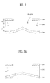
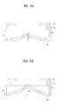
- FIGS. 14A and 14B illustrate schematic views each showing a first reflective portion having a sloped surface, wherein FIG. 14A illustrates a case the sloped surface is flat, and FIG. 14B illustrates a case the sloped surface is curved.
- one side surface of the first reflective portion 200 can have a sloped surface sloped at an angle with respect to the other side surface of the first reflective portion 200.
- the sloped surface can be sloped at an angle of 1 - 85 degrees with respect to a horizontal plane parallel to the other side surface of the first reflective portion 200.
- the thickness of the first reflective portion 200 decreases as the first reflective portion 200 goes the farther from the light source module 100.
- the surface of the first reflective portion can have a predetermined reflective pattern.
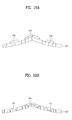
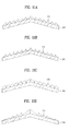
- FIGS. 15A to 15D illustrate schematic views each showing the first reflective portion having the reflective pattern.
- FIG. 15A illustrates a saw-tooth shaped reflective pattern 220 having flat saw-tooth surfaces
- FIGS. 15B and 15C illustrate saw-tooth shaped reflective patterns 220 each having curved saw-tooth surface.
- the curved saw-tooth surfaces of the reflective pattern 220 in FIG. 15B is curved upward, and the curved saw-tooth surfaces of the reflective pattern 220 in FIG. 15CB is curved downward.
- a size of the reflective pattern 220 can become the greater gradually as the reflective pattern 220 goes toward the open region from the end of the first reflective portion 200 the more.
- the reflective pattern 220 is formed on the first reflective portion 200, not only for reflection of the light, but also for providing a diffusion effect in which the light spread uniformly.
- the reflective pattern 220 can be provided to a relevant region in a variety of sizes according to an overall brightness distribution of the backlight unit.
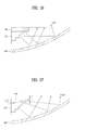
- FIGS. 16 and 17 illustrate schematic views each showing one edge type backlight unit in accordance with a preferred embodiment of the present invention., wherein FIG. 16 illustrates a schematic view of the one edge type backlight having the first reflective portion without the sloped surface, and FIG. 17 illustrates a schematic view of the one edge type backlight having the first reflective portion the sloped surface.
- the first reflective portion 200 has one side region opened, and the light source module 100 can be arranged at an edge region of the other side of the first reflective portion 200.
- the one edge type backlight unit in FIG. 16 can use types of the light source module 100 and the first and second reflective portions 200 and 300 different from the two edge type backlight unit in FIG. 1A .
- the intensity of the light from the light source module 100 used in the one edge type backlight unit is greater than the light source module 100 used in the two edge type backlight unit.
- the thickness and the length of the first reflective portion 200 are greater than the first reflective portion 200 used in the two edge type backlight unit.
- the first reflective portion 200 used in the one edge type backlight unit has the sloped surface.
- the thickness t1 at one side end of the first reflective portion 200 can be thicker than the thickness t2 at the other side end of the first reflective portion 200.
- the first reflective portion 200 can be formed to have a thickness which decreases as the first reflective portion 200 goes the farther from the light source module 100.
- the sloped surface of the first reflective portion 200 can be sloped at 1 - 85 degrees from a horizontal plane parallel to the other side surface of the first reflective portion 200.
- the first reflective portion 200 can be formed of a reflective coating film, or a reflective coating material layer.
- FIG. 18 illustrates a schematic view showing an arrangement of the optical sheet
- FIG. 19 illustrates a schematic view of a shape of the optical sheet.
- the optical sheet 600 can be arranged at the open region of the first reflective portion 200, and have an uneven pattern 620 on an upper surface thereof.
- the optical sheet 600 provided for diffusing the light through the open region of the first reflective portion 200, can have the uneven pattern 620 formed on the upper surface of the diffusion sheet 600.
- the uneven pattern 620 can have a strip shape arranged along the light source module 100.
- the uneven pattern 620 can have projections from a surface of the optical sheet 600 each having a first surface and a second surface opposite to each other with an obtuse or acute angle between the first surface and the second surface.
- the backlight unit fabricated thus can include the first reflective portion 200 having an open center region, the second reflective portion 300 arranged opposite to an underside surface of the first reflective portion 200 spaced a distance away from the underside surface of the first reflective portion 200 to form an air guide, and first and second light source modules 100a and 100b arranged on opposite regions between the first and second reflective portions 200 and 300 opposite to each other.
- the second reflective portion 300 can include a first sloped surface 300a positioned on a lower side of the first light source module 100a sloped in the second light source module 100b direction, a second sloped surface 300b extended from the first sloped surface 300a opposite to the first sloped surface 300a sloped in the first light source module 100a direction, a third sloped surface 300c extended from the second sloped surface 300b sloped in the second light source module 100b direction, and a fourth sloped surface 300d extended from the third sloped surface 300c opposite to the third sloped surface 300c positioned on a lower side of the second light source module 100b sloped in the first light source module 100a direction.
- the first reflective portion can have a reflective pattern different from the second reflective portion.
- the first reflective portion can have a reflective surface which reflects the light regularly
- the second reflective portion can have a reflective surface which reflects the light irregularly.
- the first reflective portion can have a reflective surface which reflects the light irregularly
- the second reflective portion can have a reflective surface which reflects the light regularly.
- first, second, third, and fourth sloped surfaces 300a, 300b, 300c, and 300d can have identical, or different, reflective surfaces.
- first and fourth sloped surfaces 300a and 300d of the second reflective portion 300 can have reflective surfaces which reflect the light regularly
- the second and third sloped surfaces 300b and 300d of the second reflective portion 300 can have reflective surfaces which reflect the light irregularly.
- first and fourth sloped surfaces 300a and 300d of the second reflective portion 300 can have reflective surfaces which reflect the light irregularly
- the second and third sloped surfaces 300b and 300d of the second reflective portion 300 can have reflective surfaces which reflect the light regularly.
- the second reflective portion 300 of the backlight unit can include a first groove formed between the first sloped surface 300a and the second sloped surface 300b, and a second groove formed between the third sloped surface 300c and the fourth sloped surface 300d.
- the first groove is formed along the first light source module 100a adjacent to the first light source module 100a, and can have opposite sloped sides.
- the second groove is formed along the second light source module 100b adjacent to the second light source module 100b, and can have opposite sloped sides.
- first groove and the second groove can be formed symmetry with each other with respect to the center region.
- the embodiment suggests arranging a light emission surface of the light source module in a variety of directions.
- FIG. 18 illustrates the light source module 100 having a direct emitting type of the light emission surface in which the light source module 100 faces an inside of the backlight unit, as shown in FIGS. 23a and 23e , the light source module 100 can be arranged to have an indirect emitting type of the light emission surface.
- the light source module 100 can be attached to the cover frame 400 directly, as shown in FIGS.23a and 23G , the light source module 100 is attached to a rotatable frame 412, and, in turn, the rotatable frame 412 is fastened to the cover frame 400 with a rotation adjusting screw 411.
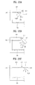
- FIGS. 23A to 23G illustrate schematic views each showing the light emission direction of the light source module, wherein FIG. 23A illustrates the rotatable frame 412 turned by 90degrees from the cover frame 400, arranging the light emission surface of the light source module 100 to a side direction of the cover frame 400.
- the light from the light source module 100 can be reflected at the cover frame 400, the first reflective portion 200, or the second reflective portion 300, and travel to an inside direction of the backlight unit.
- the light source module 100 is arranged in such an indirect emitting type for reducing a hot spot phenomenon.
- FIG. 23B illustrates the rotatable frame 412 turned by 135 degrees from the cover frame 400, arranging the light emission surface of the light source module 100 in side and bottom surface directions of the cover frame 400.
- FIG. 23C illustrates the rotatable frame 412 turned by 180 degrees from the cover frame 400, arranging the light emission surface of the light source module 100 in the bottom surface directions of the cover frame 400.
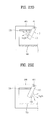
- FIG. 23D illustrates the rotatable frame 412 turned by 45 degrees from the cover frame 400, arranging the light emission surface of the light source module 100 in upper and side surface directions of the cover frame 400
- FIG. 23E illustrates the rotatable frame 412 turned by 45 degrees from the cover frame 400, arranging the light emission surface of the light source module 100 in the bottom surface direction of the cover frame 400 and the inside direction of the backlight unit.
- the light source module 100 can have the light emission surface arranged in a variety of directions by rotating the rotatable frame 412.
- the light source module 100 can be positioned on the bottom plate of the cover frame 400.
- the light source module is positioned on the bottom plate of the cover frame 400, arranging the light emission surface of the light source module 100 in an upper surface direction of the cover frame 400 and in an inside direction of the backlight unit.
- the light source module 100 can be in contact with the side surface of the cover frame 400 as shown in FIG. 23F , or the light source module can be arranged spaced from the side surface of the cover frame 400 as shown in FIG. 23G .
- the embodiment suggests the light source module 100 arranging in contact with, or adjacent to, the second reflective portion 300.
- the optical sheet since the optical sheet is required to secure a predetermined air guide, the optical sheet is not arranged on the first reflective portion 200 as shown in FIG. 18 , but is required to be supported by the supporting frame of the cover frame.
- FIG. 24 illustrates a schematic view of the optical sheet supported on the cover frame.
- the cover frame 400 can have a supporting frame 413 for supporting the optical sheet 600, additionally.
- optical sheet 600 can be supported by the supporting frame 413 of the cover frame 400.
- the optical sheet 600 is arranged thus for securing an air guide between the second reflective portion 300 and the optical sheet 600.
- the thickness of the backlight unit can be reduced, and by securing the air guide between the optical sheet 600 and the second reflective portion 300, uniform brightness is obtainable.
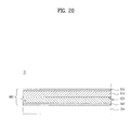
- FIG. 20 illustrates a schematic view of a display module having a backlight unit in accordance with a preferred embodiment of the present invention.
- the display module 20 can include a display panel 800 and a backlight unit 700.
- the display panel 800 includes a color filter substrate 810 and a TFT (Thin Film Transistor) substrate 820 bonded together to face each other for maintaining a uniform cell gap, and there can be a liquid crystal layer (not shown) disposed between the two substrates 810 and 820.
- TFT Thin Film Transistor
- the color filter substrate 810 includes a plurality of pixels each having a red R, a green G, and a blue B sub-pixels, for producing an image relevant to colors of red, green and blue when a light is applied thereto.
- each of the pixels can have the red R, the green G, and the blue B sub-pixels
- each of the pixels can have sub-pixels not limited to above, but the each of the pixels can have the red R, the green G, the blue B and a white W sub-pixels.
- the TFT substrate 820 is an element having switching devices formed thereon, for switching pixel electrodes (not shown).
- a common electrode (not shown) and the pixel electrode can change orientation of molecules of the liquid crystal layer according to a predetermined voltage applied thereto from an outside.
- the liquid crystal layer has a plurality of liquid crystal molecules, and the liquid crystal molecules change the orientation matched to a voltage difference taken place between the pixel electrode and the common electrode.
- the light provided from the backlight unit 700 can be incident on the color filter substrate 810 in conformity with the change of orientation of the molecules of the liquid crystal layer.
- the display panel 800 can have an upper polarization plate 830 and a lower polarization plate 840 arranged on upper and lower sides of the display panel 800.
- the upper polarization plate 830 is arranged on an upper surface of the color filter substrate 810
- the lower polarization plate 840 is arranged on an underside surface of the TFT substrate 820.
- gate and data drivers for generating driving signals for driving the panel 800.
- the display module can be fabricated by putting the backlight unit 700 to the display panel 800 in tight contact.
- the backlight unit 700 can be adhered and secured to the underside surface of the display panel 800, more specifically, to the lower polarization plate 840, and for this, there can be an adhesive layer formed between the lower polarization plate 840 and the backlight unit 700.
- a total thickness of the display device can be reduced to improve an outside appearance, and a structure and a fabrication process of the display device can be simplified as additional structures for fastening the backlight unit 700 is removed from the display device.
- the removal of the space between the backlight unit 700 and the display panel 800 enables to prevent the display device from malfunctioning or providing a poor picture quality caused by infiltration of foreign matters into the space.
- the backlight unit 700 in accordance with a preferred embodiment of the present invention can be configured to have a stack of a plurality of functional layers of which at least one layer is provided with a plurality of light sources (not shown).
- the backlight unit 700 In order to put in tight contact and secure the backlight unit 700 to the display panel 800, the backlight unit 700, more specifically, the plurality of functional layers of the backlight unit 700 can be formed of flexible materials.
- the display panel 800 in accordance with a preferred embodiment of the present invention can be divided into a plurality of regions, and as brightness of the light from a region of the backlight unit 700, i.e., brightness of a light source is controlled according to a gray peak value or a chromaticity signal of each of the divided regions, the brightness of the display panel 800 can be controlled.
- the backlight unit 700 can be operated divided into a plurality of divided driving regions matched to the divided regions of the display panel 800.
- FIGS. 21 and 22 illustrate schematic views each showing a display device in accordance with a preferred embodiment of the present invention.
- the display device 1 can include a display module 20, a front cover 30 and a back cover 35 for enclosing the display module 20, a driving unit 55 provided to the back cover 35, and a driving unit cover 40 for covering the driving unit 55.
- the front cover 30 can include a front panel (not shown) of a transparent material spaced from the display module 20 to transmit a light, for protecting the display module 20 and transmitting the light from the display module 20 enabling to make the image displayed on the display module 20 visible from an outside of the display device 1.
- the front cover 30 can be formed as a flat plate without a window 30a.
- the front cover 30 is formed of a transparent material which transmits the light, for an example, injection molded plastic.
- front cover 30 is flat, a frame can be removed from the front cover 30.
- the back cover 35 can be coupled to the front cover 30 for protecting the display module 20.
- the driving unit 55 arranged on one surface thereof.
- the driving unit 55 can include a driving control unit 55a, a main board 55b, and a power supply unit 55c.
- the driving control unit 55a can be a timing controller, for controlling operation timing of driver ICs in the display module 20, the main board 55b is driving unit for forwarding a V synchronizing signal, an H synchronizing signal, and R, G, B resolution signals to the timing controller, and the power supply unit 55c is a driving unit for applying power to the display module 20.
- the driving unit 55 is provided to the back cover 35 and can be covered with the driving unit cover 40.
- the back cover 35 has a plurality of holes provided therein for connecting the display module 20 to the driving unit 55, and can have the stand 60 for supporting the display unit 1.
- the driving control unit 55a of the driving unit 55 can be provided to the back cover 35, and the main board 55b and the power supply unit 55c can be provided to the stand 60.
- the driving unit cover 40 can cover the driving unit 55 provided to the back cover 35.
- the embodiment suggests separate main board 55b and power supply unit 55c, the main board 55b and the power supply unit 55c can be united as one unit of board, but the present invention does not limit to this.
- the backlight unit of the present invention has the following advantages.
- the light from the light source can be reflected uniformly to provide uniform brightness by using the first reflective portion having a reflective surface parallel to a horizontal plane and a reflective portion having a reflective portion with a surface sloped at an angle from the horizontal surface, no additional mechanical unit is required.
Landscapes
- Physics & Mathematics (AREA)
- Engineering & Computer Science (AREA)
- General Physics & Mathematics (AREA)
- Optics & Photonics (AREA)
- General Engineering & Computer Science (AREA)
- Theoretical Computer Science (AREA)
- Microelectronics & Electronic Packaging (AREA)
- Planar Illumination Modules (AREA)
- Liquid Crystal (AREA)
- Led Device Packages (AREA)
Abstract
Description
- The present invention relates to a backlight unit having reflective portions.
- In general, as a typical large sized display device, there are LCD (Liquid Crystal Display Device), PDP (Plasma Display Panel) and so on.
- Different from a spontaneous light emission type PDP, since the LCD has no light emission device for itself, the LCD requires a separate backlight unit, essentially.
- In the backlight unit of the LCD, there are an edge light type backlight unit, and a direct light type backlight unit depending on positions of a light source of the backlight unit, wherein, since the edge light type has the light source arranged at a left or right side or an upper or lower side of the LCD panel for distribution of a light throughout an entire surface of the screen by using a light guide plate, the edge light type has good light uniformity and enables to fabricate a thin display device.
- Since the direct light type, which is a technology used in general for the display device greater than 20", has a plurality of the light sources arranged on a lower side of the panel, the direct light type has an advantage in optical efficiency over the edge light type to use in the large sized display device that requires high brightness, mostly.
- As the light source of the related art edge light type or direct light type backlight unit, a CCFL (Cold Cathode Fluorescent Lamp) is used.
- However, since the backlight unit of CCFL has power always applied to the CCFL, the backlight unit has drawbacks in that a substantial amount of power is consumed, a color reproduction ratio is about 70% level compared to a CRT, and mercury contained in the CCFL causes environmental contamination.
- As a substitutional product for solving above problems, active researches on the backlight unit with an LED (Light Emitting Diode) are underway, presently.
- If the LED is used in the backlight unit, since local turn on/off is possible, substantial reduction of power consumption is possible, and RGB LEDs having a color reproduction range well over 100% of the NTSC (National Television System Committee) specification can provide a lively picture to consumers.
- Moreover, it is a feature that the LED manufactured by a semiconductor fabrication process is harmless to the environment.
- Though LCD products which adopt the LED that has above advantages appear in succession, since the products have driving mechanisms different from the related art CCFL light source, the drivers, and PCB boards are expensive.
- Consequently, the LED backlight unit is applied only to high price LCD products, still.
- Accordingly, the present invention is directed to a backlight unit.
- An object of the present invention is to provide a backlight unit in which a light source module is positioned between two reflective portions each having an air guide for providing a light of uniform brightness, and which can simplify a structure thereof.
- Additional advantages, objects, and features of the disclosure will be set forth in part in the description which follows and in part will become apparent to those having ordinary skill in the art upon examination of the following or may be learned from practice of the invention. The objectives and other advantages of the invention may be realized and attained by the structure particularly pointed out in the written description and claims hereof as well as the appended drawings.
- To achieve these objects and other advantages and in accordance with the purpose of the invention, as embodied and broadly described herein, a backlight unit can include a light source module for emitting a light, a first reflective portion arranged spaced a first distance away from one side of the light source module to have an open region, and a second reflective portion arranged spaced a second distance which is greater than the first distance away from the other side of the light source module to have at least a portion with a sloped surface for reflecting the light toward the open region of the first reflective portion.
- In this instance, the first reflective portion can have an opened center region, and the light source module can include a first light source module and a second light source module arranged at opposite edges of the first reflective portion to face each other.
- And, the first reflective portion can have one opened side region, and the light source module can be arranged at the other edge region of the first reflective portion.
- And, the sloped surface of the second reflective portion can be one of a flat surface, a downward curved surface, or an upward curved surface.
- Then, the second reflective portion can have at least a portion of which slope angle has a pattern in which the slope angle decreases in middle of increase, or the second reflective portion can have at least a portion of which slope angle has a pattern in which the slope angle decreases in middle of no change of the slope angle after increase of the slope angle.
- Next, the second reflective portion can include a first sub-reflective portion having a first sloped surface, and a second sub-reflective portion connected to an end of the first sub-reflective portion to have a first sloped surface formed to have a slope angle different from the slope angle of the first sloped surface.
- And, the backlight unit can further include a cover frame for supporting the first and second reflective portions and the light source module, wherein the cover frame can include a first supporting portion arranged parallel to the first reflective portion for supporting the first reflective portion, the first reflective portion having an open region, and a second supporting portion extended perpendicular to the first reflective portion from an end of the first reflective portion for supporting the light source module, and a third supporting portion extended parallel to the first reflective portion from an end of the second reflective portion for supporting the second reflective portion.
- Then, the second reflective portion can include a bottom plate having a sloped surface sloped at an angle from a horizontal plane parallel to a surface of the first reflective portion, and a reflective sheet formed on the sloped surface of the bottom plate.
- In this instance, the reflective sheet can be formed on a portion or an entire surface of the sloped surface, and the reflective sheet can have the same reflectivity throughout the sloped surface or different reflectivity at a portion thereof.
- Depending on cases, the bottom plate has a recess in an entire, or a portion of, the sloped surface, and the reflective sheet is formed in the recess in the bottom plate.
- Next, the first reflective portion has one side surface opposite to the second reflective portion with a saw-tooth shaped reflective pattern, and a surface of the reflective pattern is flat or curved.
- In another aspect of the present invention, a backlight unit can include a light source module for emitting a light, a first reflective portion arranged in contact with one side of the light source module to have an open region, and a second reflective portion arranged spaced a distance away from the other side of the light source module to have at least a portion with a sloped surface for reflecting the light toward the open region of the first reflective portion.
- And, in another aspect of the present invention, a backlight unit can include a first reflective portion having an opened center region, a second reflective portion arranged opposite to, and a distance away from an underside surface of the first reflective portion to have an air guide therebetween, first and second light source modules arranged at opposite regions between the first and second reflective portions opposite to each other, wherein the second reflective portion can include a first sloped surface positioned on a lower side of the first light source module sloped in a second light source module direction,
a second sloped surface extended from the first sloped surface to opposite to the first sloped surface and sloped in a first light source module direction, a third sloped surface extended from the second sloped surface and sloped in a second light source module direction, and a fourth sloped surface extended from the third sloped surface to opposite to the third sloped surface and position on a lower side of the second light source module and sloped in a first light source module direction. - It is to be understood that both the foregoing general description and the following detailed description of the present invention are exemplary and explanatory and are intended to provide further explanation of the invention as claimed.
- The accompanying drawings, which are included to provide a further understanding of the disclosure and are incorporated in and constitute a part of this application, illustrate embodiment(s) of the disclosure and together with the description serve to explain the principle of the disclosure. In the drawings:
-
FIGS. 1A and 1B illustrate schematic views each showing a two edge type backlight unit in accordance with a preferred embodiment of the present invention. -
FIG. 2 illustrates a schematic view showing a configuration of the light source module and the first and second reflective portions inFIG. 1 . -
FIGS. 3A to 3D illustrate schematic views each showing a sloped surface of a second reflective portion. -
FIGS. 4A and 4B illustrate schematic views each showing a second reflective portion having a plurality of sloped surfaces. -
FIGS. 5A and 5B illustrate schematic views each showing a height of an end of a sloped surface of a second reflective portion. -
FIGS. 6 to 8 illustrate schematic views each showing a cover frame for supporting a light source module and first and second reflective portions. -
FIGS. 9A and 9B illustrate schematic views each showing a shape of a frame having a second reflective portion attached to an entire surface thereof. -
FIGS. 10A and 10B illustrate schematic views each showing a shape of a frame having a second reflective portion attached to a portion thereof. -
FIGS. 11A to 11D illustrate schematic views each showing a second reflective portion having a reflective pattern. -
FIGS. 12 and 13 illustrate schematic views for explaining thickness and length conditions of the first reflective portion. -
FIGS. 14A and 14B illustrate schematic views each showing a first reflective portion having a sloped surface. -
FIGS. 15A to 15D illustrate schematic views each showing a first reflective portion having a reflective pattern. -
FIGS. 16 and 17 illustrate schematic views each showing one edge type backlight unit in accordance with a preferred embodiment of the present invention. -
FIG. 18 illustrates a schematic view showing an arrangement of an optical sheet. -
FIG. 19 illustrates a schematic view of a shape of an optical sheet. -
FIG. 20 illustrates a schematic view of a display module having a backlight unit in accordance with a preferred embodiment of the present invention. -
FIGS. 21 and22 illustrate schematic views each showing a display device in accordance with a preferred embodiment of the present invention. -
FIGS. 23A to 23G illustrate schematic views each showing a light emission direction of a light source module. -
FIG. 24 illustrates a schematic view of an optical sheet supported on a cover frame. - Reference will now be made in detail to the specific embodiments of the present invention, examples of which are illustrated in the accompanying drawings. Wherever possible, the same reference numbers will be used throughout the drawings to refer to the same or like parts.
- It is required to understand that, in a description that a layer (a film), a region, a pattern, or a structure is formed "on" or "under" a substrate, a layer (a film) a region, a pad, or pattern, the "on", or "under" implies that the layer (the film), the region, the pattern, or the structure is formed directly or indirectly. And, reference on the "on" or "under" is the drawing.
- A thickness or a size of a layer shown in a drawing is exaggerated, omitted or shown schematically for convenience or clarity of description. And, a size of an element is not shown to scale, perfectly.
-
FIGS. 1A and 1B illustrate schematic views each showing a two edge type backlight unit in accordance with a preferred embodiment of the present invention, whereinFIG. 1A illustrates a section thereof andFIG. 1B illustrates a perspective view thereof. - Referring to
FIGS. 1A and 1B , the backlight unit can include alight source module 100, a firstreflective portion 200 and a secondreflective portion 300. - In this instance, the
light source module 100 is positioned between the firstreflective portion 200 and the secondreflective portion 300 adjacent to the firstreflective portion 200. - And, the
light source module 100 can include a circuit board having an electrode pattern and a light emission device for emitting a light. - In this instance, the circuit board can have at least one light emission device mounted thereon, and the electrode pattern for connecting a power supply adapter to the light emission device formed thereon.
- For an example, the circuit board can have a carbon nano-tube electrode pattern formed thereon for connecting the adapter to the light emission device.
- The circuit board can be a PCB (Printed Circuit Board) of polyethylene terephthalate (PET), glass, polycarbonate PC, or silicon (Si) for mounting a plurality of
light sources 100 thereon, or can be formed as a film shape. - In the meantime, the light emission device can be a light emission diode (LED) chip having a blue LED chip or an UV LED chip, or a package having a combination of at least one or more than one of red LED chip, green LED chip, blue LED chip, yellow green LED chip, and white LED chip.
- And, the white LED can be produced by combining yellow phosphor with the blue LED or using red phosphor and green phosphor at a time.
- In order to have an air guide in an empty space between the first
reflective portion 200 and the secondreflective portion 300, the firstreflective portion 200 and the secondreflective portion 300 can be spaced a distance away from, and opposite to, each other. - In this instance, the first
reflective portion 200 has an open region, and is arranged in contact with one side of, or spaced from, thelight source module 100. - That is, the first
reflective portion 200 has an open center region, and thelight source module 100 can include a first light source module and a second light source module arranged opposite to each other at opposite edge region of the firstreflective portion 200. - And, the first
reflective portion 200 is formed of a reflective coating film or a reflective coating material, for reflecting the light from thelight source module 100 toward the secondreflective portion 300. - The first
reflective portion 200 has a surface opposite to thelight source module 100 with a saw-tooth shaped reflective pattern formed thereon, wherein the reflective pattern can have a flat or curve surface. - The reflective pattern is formed on the surface of the first
reflective portion 200 for reflecting the light from the light source module toward the center region of the secondreflective portion 300 to increase brightness of the center region of the backlight unit. - Next, the second
reflective portion 300 is arranged spaced a distance away from thelight source module 100 and can have a sloped surface sloped at an angle from a horizontal plane parallel to the surface of the firstreflective portion 200. - In this instance, the sloped surface of the second
reflective portion 300 serves to reflect the light from thelight source module 100 or reflected at the firstreflective portion 200 to the open region of the firstreflective portion 200. - And, it is preferable that a distance between the second
reflective portion 300 and thelight source module 100 is greater than a distance between the firstreflective portion 200 and thelight source module 100. - This is for increasing brightness of the center region of the backlight unit by making the light from the light source module to converge on the center region more.
-
FIG. 2 illustrates a schematic view showing a configuration of the light source module and the first and second reflective portions inFIG. 1 . - Referring to
FIG. 2 , it can be noticed that a first distance d1 between the firstreflective portion 200 and thelight source module 100 is smaller than a second distance d2 between the secondreflective portion 300 and thelight source module 100. - That is, the
light source module 100 is positioned at opposite sides in the air guide between the first and secondreflective portions reflective portion 200 more than the secondreflective portion 300. - Thus, since the second
reflective portion 300 has the surface opposite to the firstreflective portion 200 sloped at an angle from the horizontal plane, a distance between the firstreflective portion 200 and the secondreflective portion 300 can be greater at a region close to thelight source module 100 than at a region far from thelight source module 100. -
FIGS. 3A to 3D illustrate schematic views each showing the sloped surface of the second reflective portion, whereinFIG. 3A illustrates a flat sloped surface andFIGS. 3B to 3D illustrate curved sloped surfaces, respectively. - Referring to
FIG. 3A , the sloped surface of the secondreflective portion 300 can be flat with the angle θ1 between the sloped surface of the secondreflective portion 300 and the horizontal plane parallel to the surface of the firstreflective portion 200 being approx. 1 - 85 degrees. - And, referring to
FIG. 3B , the sloped surface of the secondreflective portion 300 can be a downward curved surface with the angle θ2 between the sloped surface of the secondreflective portion 300 and the horizontal plane parallel to the surface of the firstreflective portion 200 being increasing gradually from approx. 1 - 85 degrees. - Then, referring to
FIG. 3C , the sloped surface of the secondreflective portion 300 can be an upward curved surface with the angle θ3 between the sloped surface of the secondreflective portion 300 and the horizontal plane parallel to the surface of the firstreflective portion 200 being decreasing gradually from approx. 1 - 85 degrees. - Thus, though the sloped surface of the second
reflective portion 300 can have a pattern in which at least the slope angle of a portion thereof decreases in middle of increase, as shown inFIG. 3D , the slope angle of at least a portion of the secondreflective portion 300 can have a pattern in which the slope angle decreases in middle of no change of the slope angle after the slope angle increases. - Thus, the sloped surface of the second
reflective portion 300 can have additional sloped surfaces added to both ends of the secondreflective portion 300. -
FIGS. 4A and 4B illustrate schematic views each showing a second reflective portion having a plurality of sloped surfaces, whereinFIG. 4A illustrates the second reflective portion having two types of reflective portions, andFIG. 4B illustrates the second reflective portion having two types of sloped surfaces. - Referring to
FIG. 4A , the secondreflective portion 300 can include a firstsub-reflective portion 330 and a secondsub-reflective portion 310. - In this instance, the first
sub-reflective portion 330 is positioned on a lower side of one sidelight source module 100 to have a first sloped surface sloped in alight source module 100 direction on the other side. - And, the second
sub-reflective portion 310 is positioned at the center region and connected to an end of the firstsub-reflective portion 330 to have a second sloped surface opposite to the first sloped surface. - In this instance, an angle θ4 between the sloped surface of the first
sub-reflective portion 330 and the horizontal plane parallel to the surface of the firstreflective portion 200 can be approx. 1 - 85degrees. - Thus, the first
sub-reflective portion 330 is arranged additionally for increasing brightness of the center region of the backlight unit by reflecting the light from the light source module at the other side to the center region of the secondreflective portion 300. - Depending on cases, the slope angle of the sloped surface of the first
sub-reflective portion 330 can be different from the slope angle of the sloped surface of the secondsub-reflective portion 310. - Referring to
FIG. 4A , though the firstsub-reflective portion 330 can be a reflective structural body of a reflective material, the firstsub-reflective portion 330 can be a reflective film as shown inFIG. 4B . -
FIG. 4B illustrates the secondsub-reflective portion 310 of the reflective film having a sloped surface formed additionally to the reflective film. - Referring to
FIG. 4B , the secondreflective portion 300 can include a first sloped surface formed at a first region, and a second sloped surface formed at a second region. - In this instance, the second region is the center region and the first region is a peripheral region around the center region.
- The first sloped surface can be positioned on a lower side of the
light source module 100 and sloped in thelight source module 100 direction on the other side. - And, the second sloped surface is an extension from the first sloped surface to have a slope opposite to the first sloped surface.
- In this instance, an angle θ4 between the first sloped surface and the horizontal plane parallel to the surface of the first
reflective portion 200 is approx. 1 - 85 degrees. - Thus, the second
reflective portion 300 has the sloped surfaces for converging reflection of the light from the firstreflective portion 200 and thelight source module 100 to the open region of the firstreflective portion 200. Depending on cases, a height of an end of the sloped surface can vary. -
FIGS. 5A and 5B illustrate schematic views each showing the height of the end of the sloped surface of the second reflective portion. -
FIG. 5A illustrates a case when the height of the end of the sloped surface of the secondreflective portion 300 is positioned on a lower side of an arrange line of the light source module, andFIG. 5B illustrates a case when the height of the end of the sloped surface of the secondreflective portion 300 is positioned on an upper side of an arrange line of the light source module. - Referring to
FIG. 5A , a greatest height H1 from a lower side horizontal plane positioned at an one side end of the secondreflective portion 300 to a projected portion positioned at the center region of the secondreflective portion 300 can be smaller than both a height H2 from the horizontal plane to thelight source module 100 and a height H3 from the horizontal plane to the firstreflective portion 200. - And, referring to
FIG. 5B , a greatest height H1 from a lower side horizontal plane positioned at an one side end of the secondreflective portion 300 to a projected portion positioned at the center region of the secondreflective portion 300 can be greater than a height H2 from the horizontal plane to thelight source module 100 and smaller than a height H3 from the horizontal plane to the firstreflective portion 200. - Depending on cases, the height H2 from the horizontal plane to the
light source module 100 positioned at an one side end of the secondreflective portion 300 can be the same with the height H1 from the horizontal plane to the other side end of the secondreflective portion 300, or the height H2 from the horizontal plane to thelight source module 100 positioned at an one side end of the secondreflective portion 300 can be greater than the height H1 from the horizontal plane to the other side end of the secondreflective portion 300. - The
light source module 100, and the first and secondreflective portions -
FIGS. 6 to 8 illustrate schematic views each showing the cover frame for supporting the light source module and the first and second reflective portions. -
FIG. 6 illustrates a schematic view showing thecover frame 400 for supporting a lower end of the secondreflective portion 300,FIG. 7 illustrates a schematic view showing thecover frame 400 for supporting an entire surface of a lower side of the secondreflective portion 300, andFIG. 8 illustrates a schematic view showing thecover frame 400 formed to have a shape the same with the second reflective portion for supporting an entire surface of the lower side of the secondreflective portion 300. - At first, referring to
FIG. 6 , thecover frame 400 is arranged to support the first and secondreflective portions light source module 100. - In this instance, the
cover frame 400 can include first, second, and third supporting portions S1, S2, and S3. - The first supporting portion S1 of the
cover frame 400 can support the firstreflective portion 200, arranged in a direction parallel to the firstreflective portion 200, and have an open region at a center portion. - Then, the second supporting portion S2 can support the
light source module 100, and have an extension from an end of the first supporting portion S1 perpendicular to the firstreflective portion 200. - And, the third supporting portion S3 can support the second
reflective portion 300, and have an extension from an end of the second supporting portion S2 parallel to the first supporting portion S1. - In this instance, the third supporting portion S3 can be formed of a material the same with the first, and second first supporting portions S1 and S2, and support a lower end of the second
reflective portion 300. - The first, second, and third supporting portions S1, S2, and S3 can be formed of a metal or polymer resin.
- And, the second
reflective portion 300 can be spaced from the third supporting portion S3 at a lower side center region by a predetermined gap to form anair guide 500. - In this instance, the second
reflective portion 300 can be a reflective sheet in a shape of a reflective film. - The second
reflective portion 300 formed as the reflective sheet can have first, second, third, and fourth sloped surfaces. - The first sloped surface of the second
reflective portion 300 can be positioned on a lower side of the firstlight source module 100 positioned at one side and sloped in a secondlight source module 100 direction positioned at the other side, the second sloped surface can be extended from the first sloped surface opposite to the first sloped surface and sloped in a firstlight source module 100 direction, the third sloped surface can be extended from the second sloped surface and sloped in a secondlight source module 100 direction, and the fourth sloped surface can be extended from the third sloped surface opposite to the third sloped surface, positioned at a lower side of the secondlight source module 100, and sloped in a firstlight source module 100 direction. - Next, referring to
FIG. 7 , the third supporting portion S3 of thecover frame 400 is formed of a material the same with the first, and second supporting portions S1 and S2, and can support an entire surface of a lower side of the secondreflective portion 300. - In this instance, the second
reflective portion 300 can be a reflective structural body of a reflective material. - The second
reflective portion 300 which is the reflective structural body can have first and second grooves. - The first groove is formed along the first
light source module 100 at a region adjacent to the firstlight source module 100 positioned at one side, and can have opposite sloped sides, and the second groove is formed along the secondlight source module 100 at a region adjacent to the secondlight source module 100 positioned at the other side, and can have opposite sloped sides. - In this instance, the first groove and the second groove can be symmetry with respect to the center region of the second
reflective portion 300. - And, the third supporting portion S3 can be formed of a material the same with the first, and second supporting portions S1 and S2, and serve to support a lower side of the second
reflective portion 300. - In this instance, the first, second, and third supporting portions S1, S2, and S3 can be formed of a metal or polymer resin.
- And, referring to
FIG. 8 , the third supporting portion S3 can be formed of a material different from the first and second supporting portions S1 and S2, and can support an entire surface of a lower side of the secondreflective portion 300. - The third supporting portion S3 can be formed to have the same shape with the second
reflective portion 300 such that the third supporting portion S3 can have a sloped surface the same with the secondreflective portion 300. - Accordingly, the third supporting portion S3 can be formed of the polymer resin, such as plastic, for easy and simple fabrication in a shape the same with the second
reflective portion 300. - And, the first, and second supporting portions S1 and S2 can be formed of a metal and connected to the third supporting portion S3.
- That is, referring to
FIG. 8 , thecover frame 400 can have ametal frame 410 andpolymer resin frame 430. - Depending on cases, the
polymer resin frame 430 having the secondreflective portion 300 attached thereto can be fabricated individually and connected to thecover frame 400. -
FIGS. 9A and 9B illustrate schematic views each showing a shape of a frame having a second reflective portion attached to an entire surface thereof, whereinFIG. 9A illustrates a case when reflectivity of the second reflective portion is the same throughout the secondreflective portion 300, andFIG. 9B illustrates a case when reflectivity of the second reflective portion is not same throughout the secondreflective portion 300. - Referring to
FIGS. 9A and 9B , the secondreflective portion 300 can be the reflective coating fabricated in a film shape, or the reflective coating material layer having a reflective material deposited thereon. - The second
reflective portion 300 can include at least one of metal or metal oxide, such as aluminum, silver Ag, gold Au, or titanium dioxide TiO2 which have high reflectivity. - In this case, the second
reflective portion 300 can be formed by depositing or coating metal or metal oxide on thepolymer resin 430 which is a bottom plate, or printing metal ink. - In this instance, the metal or metal oxide can be deposited by vapor deposition such as thermal deposition, vapor deposition, or sputtering, or by printing, gravure coating or silk screen method.
- And, the second
reflective portion 300 can be formed by fabricating in a shape of a film or a sheet, and attaching the same to thepolymer resin frame 430. - In this instance, referring to
FIG. 9A , the secondreflective portion 300 can be a structure having the same reflectivity throughout the polymer resin frame which is the bottom plate, or referring toFIG. 9B , the secondreflective portion 300 can be a structure having a plurality ofreflective layers polymer resin frame 430. - The reason the second
reflective portion 300 is constructed of the plurality of reflective layers with reflectivity different from one another lies on that, if reflective layers having the same reflectivity are only formed, the optical reflectivity is not uniform throughout an entire reflective surface causing brightness of the backlight unit not uniform throughout the backlight unit. - Accordingly, by forming the reflective layer having relatively high reflectivity at a region brightness of the light is displayed low, or forming the reflective layer having relatively low reflectivity at a region brightness of the light is displayed high, the brightness throughout the backlight unit can be corrected uniform.
-
FIGS. 10A and 10B illustrate schematic views each showing a shape of a frame having a second reflective portion attached to a portion thereof, whereinFIG. 10A illustrates a schematic view of the second reflective portion projected from a surface of the polymer resin frame, andFIG. 10B illustrates a schematic view of the second reflective portion recessed in the surface of the polymer resin frame. - Alike
FIG. 9B , embodiments inFIGS. 10A and 10B also form the reflective layer only at a reflective surface region displaying the brightness of the light low for correcting the brightness throughout the backlight unit uniform. - The embodiment in
FIG. 10A can have the reflective layer of the secondreflective portion 300 projected from a portion of the surface of thepolymer resin frame 430. - And, the embodiment in
FIG. 10B can have the reflective layer of the secondreflective portion 300 recessed in a recess formed in a portion of the surface of thepolymer resin frame 430. - Thus, though the second
reflective portion 300 can be formed on an entire region of thepolymer resin frame 430, or can be formed only at a region of which brightness of the light is low relatively. - Depending on cases, the second
reflective portion 300 can have a predetermined shape of reflective pattern on a surface thereof. -
FIGS. 11A to 11D illustrate schematic views each showing a second reflective portion having a reflective pattern. -
FIG. 11A illustrates a saw-tooth shapedreflective pattern 350, and thereflective pattern 350 can have a flat surface, andFIGS. 11B and 11C illustrate saw-tooth shapedreflective patterns 350 respectively, and thereflective patterns 350 can have curved surfaces, respectively. - In this instance, the saw-tooth shaped
reflective pattern 350 inFIG. 11B has an upward curved surface, and the saw-tooth shapedreflective pattern 350 inFIG. 11C has a downward curved surface. - Depending on cases, referring to
FIG. 11D , a size of thereflective pattern 350 can become the greater as the reflective pattern goes from an end to a center portion of the secondreflective portion 300 the more. - The
reflective pattern 350 is formed on the secondreflective portion 300 thus for providing, not only a reflection effect of the light, but also a diffusion effect of the light which spreads the light uniformly. - Therefore, the
reflective pattern 350 can be formed in a variety of sizes on a relevant region according to an overall brightness distribution of the backlight unit. - In the meantime, the first
reflective portion 200 can influence to brightness uniformity of the backlight unit depending of a thickness and a length thereof. -
FIGS. 12 and 13 illustrate schematic views for explaining thickness and length conditions of the first reflective portion. - Referring to
FIG. 12 , the firstreflective portion 200 can have a length L1 from one end to the other end positioned in an open region direction, and thelight source module 100 can have a length L2 from one end to the other end positioned in an open region direction. - In this instance, the length L1 of the first
reflective portion 200 can be 5 to 10 times of the length L2 of thelight source module 100. - And, the thickness t1 of the first
reflective portion 200 can be the same with or different from the thickness t2 of the secondreflective portion 300. - Most preferably, it is favorable that the thickness t1 of the first
reflective portion 200 is greater than the thickness t2 of the secondreflective portion 300. - And, referring to
FIG. 13 , depending on cases, the thickness t1 of the firstreflective portion 200a positioned at one side of the open region can be the same with or different from the thickness t3 of the first reflective portion 200b positioned at the other side of the open region. - And, lengths of the first
reflective portions 200a and 200b positioned on both sides of the open region can be different from each other. - This is because intensity of light emission from the
light source modules 100 arranged on both sides of the open region can be different from each other. - That is, the first
reflective portion 200 arranged above thelight source module 100 having relatively high intensity of light emission is required to be thicker and longer relatively for shielding the light. -
FIGS. 14A and 14B illustrate schematic views each showing a first reflective portion having a sloped surface, whereinFIG. 14A illustrates a case the sloped surface is flat, andFIG. 14B illustrates a case the sloped surface is curved. - Referring to
FIGS. 14A and 14B , one side surface of the firstreflective portion 200 can have a sloped surface sloped at an angle with respect to the other side surface of the firstreflective portion 200. - In this instance, the sloped surface can be sloped at an angle of 1 - 85 degrees with respect to a horizontal plane parallel to the other side surface of the first
reflective portion 200. - Accordingly, the thickness of the first
reflective portion 200 decreases as the firstreflective portion 200 goes the farther from thelight source module 100. - And, the surface of the first reflective portion can have a predetermined reflective pattern.
-
FIGS. 15A to 15D illustrate schematic views each showing the first reflective portion having the reflective pattern. -
FIG. 15A illustrates a saw-tooth shapedreflective pattern 220 having flat saw-tooth surfaces, andFIGS. 15B and 15C illustrate saw-tooth shapedreflective patterns 220 each having curved saw-tooth surface. - In this instance, the curved saw-tooth surfaces of the
reflective pattern 220 inFIG. 15B is curved upward, and the curved saw-tooth surfaces of thereflective pattern 220 inFIG. 15CB is curved downward. - Referring to
FIG. 15D , depending on cases, a size of thereflective pattern 220 can become the greater gradually as thereflective pattern 220 goes toward the open region from the end of the firstreflective portion 200 the more. - The
reflective pattern 220 is formed on the firstreflective portion 200, not only for reflection of the light, but also for providing a diffusion effect in which the light spread uniformly. - Therefore, the
reflective pattern 220 can be provided to a relevant region in a variety of sizes according to an overall brightness distribution of the backlight unit. -
FIGS. 16 and 17 illustrate schematic views each showing one edge type backlight unit in accordance with a preferred embodiment of the present invention., whereinFIG. 16 illustrates a schematic view of the one edge type backlight having the first reflective portion without the sloped surface, andFIG. 17 illustrates a schematic view of the one edge type backlight having the first reflective portion the sloped surface. - Referring to
FIG. 16 , the firstreflective portion 200 has one side region opened, and thelight source module 100 can be arranged at an edge region of the other side of the firstreflective portion 200. - The one edge type backlight unit in
FIG. 16 can use types of thelight source module 100 and the first and secondreflective portions FIG. 1A . - For an example, it is preferable that the intensity of the light from the
light source module 100 used in the one edge type backlight unit is greater than thelight source module 100 used in the two edge type backlight unit. - In this case, if the
light source module 100 having a relatively high light emission is used, it is required that the thickness and the length of the firstreflective portion 200 are greater than the firstreflective portion 200 used in the two edge type backlight unit. - And, referring to
FIG. 17 , it is preferable that the firstreflective portion 200 used in the one edge type backlight unit has the sloped surface. - This is for obtaining overall uniform brightness by reflecting the light from the
light source module 100 far from thelight source module 100. - Accordingly, the thickness t1 at one side end of the first
reflective portion 200 can be thicker than the thickness t2 at the other side end of the firstreflective portion 200. - That is, the first
reflective portion 200 can be formed to have a thickness which decreases as the firstreflective portion 200 goes the farther from thelight source module 100. - In this instance, the sloped surface of the first
reflective portion 200 can be sloped at 1 - 85 degrees from a horizontal plane parallel to the other side surface of the firstreflective portion 200. - And, the first
reflective portion 200 can be formed of a reflective coating film, or a reflective coating material layer. -
FIG. 18 illustrates a schematic view showing an arrangement of the optical sheet, andFIG. 19 illustrates a schematic view of a shape of the optical sheet. - Referring to
FIG. 18 , theoptical sheet 600 can be arranged at the open region of the firstreflective portion 200, and have anuneven pattern 620 on an upper surface thereof. - In this instance, the
optical sheet 600, provided for diffusing the light through the open region of the firstreflective portion 200, can have theuneven pattern 620 formed on the upper surface of thediffusion sheet 600. - Referring to
FIG. 19 , theuneven pattern 620 can have a strip shape arranged along thelight source module 100. - In this instance, the
uneven pattern 620 can have projections from a surface of theoptical sheet 600 each having a first surface and a second surface opposite to each other with an obtuse or acute angle between the first surface and the second surface. - Referring to
FIG. 18 , the backlight unit fabricated thus can include the firstreflective portion 200 having an open center region, the secondreflective portion 300 arranged opposite to an underside surface of the firstreflective portion 200 spaced a distance away from the underside surface of the firstreflective portion 200 to form an air guide, and first and secondlight source modules reflective portions - In this instance, the second
reflective portion 300 can include a first slopedsurface 300a positioned on a lower side of the firstlight source module 100a sloped in the secondlight source module 100b direction, a secondsloped surface 300b extended from the first slopedsurface 300a opposite to the first slopedsurface 300a sloped in the firstlight source module 100a direction, a thirdsloped surface 300c extended from the secondsloped surface 300b sloped in the secondlight source module 100b direction, and a fourth slopedsurface 300d extended from the thirdsloped surface 300c opposite to the thirdsloped surface 300c positioned on a lower side of the secondlight source module 100b sloped in the firstlight source module 100a direction. - In this instance, the first reflective portion can have a reflective pattern different from the second reflective portion.
- That is, the first reflective portion can have a reflective surface which reflects the light regularly, and the second reflective portion can have a reflective surface which reflects the light irregularly.
- Or, the first reflective portion can have a reflective surface which reflects the light irregularly, and the second reflective portion can have a reflective surface which reflects the light regularly.
- And, the first, second, third, and fourth
sloped surfaces - For an example, the first and fourth
sloped surfaces reflective portion 300 can have reflective surfaces which reflect the light regularly, and the second and thirdsloped surfaces reflective portion 300 can have reflective surfaces which reflect the light irregularly. - Or, the first and fourth
sloped surfaces reflective portion 300 can have reflective surfaces which reflect the light irregularly, and the second and thirdsloped surfaces reflective portion 300 can have reflective surfaces which reflect the light regularly. - Depending on cases, the second
reflective portion 300 of the backlight unit can include a first groove formed between the first slopedsurface 300a and the secondsloped surface 300b, and a second groove formed between the thirdsloped surface 300c and the fourth slopedsurface 300d. - In this instance, the first groove is formed along the first
light source module 100a adjacent to the firstlight source module 100a, and can have opposite sloped sides. - And, the second groove is formed along the second
light source module 100b adjacent to the secondlight source module 100b, and can have opposite sloped sides. - In this instance, the first groove and the second groove can be formed symmetry with each other with respect to the center region.
- In the meantime, the embodiment suggests arranging a light emission surface of the light source module in a variety of directions.
- Though
FIG. 18 illustrates thelight source module 100 having a direct emitting type of the light emission surface in which thelight source module 100 faces an inside of the backlight unit, as shown inFIGS. 23a and23e , thelight source module 100 can be arranged to have an indirect emitting type of the light emission surface. - That is, referring to
FIG. 18 , though thelight source module 100 can be attached to thecover frame 400 directly, as shown inFIGS.23a and23G , thelight source module 100 is attached to arotatable frame 412, and, in turn, therotatable frame 412 is fastened to thecover frame 400 with arotation adjusting screw 411. -
FIGS. 23A to 23G illustrate schematic views each showing the light emission direction of the light source module, whereinFIG. 23A illustrates therotatable frame 412 turned by 90degrees from thecover frame 400, arranging the light emission surface of thelight source module 100 to a side direction of thecover frame 400. - The light from the
light source module 100 can be reflected at thecover frame 400, the firstreflective portion 200, or the secondreflective portion 300, and travel to an inside direction of the backlight unit. - The
light source module 100 is arranged in such an indirect emitting type for reducing a hot spot phenomenon. - Next,
FIG. 23B illustrates therotatable frame 412 turned by 135 degrees from thecover frame 400, arranging the light emission surface of thelight source module 100 in side and bottom surface directions of thecover frame 400. - And,
FIG. 23C illustrates therotatable frame 412 turned by 180 degrees from thecover frame 400, arranging the light emission surface of thelight source module 100 in the bottom surface directions of thecover frame 400. - Next,
FIG. 23D illustrates therotatable frame 412 turned by 45 degrees from thecover frame 400, arranging the light emission surface of thelight source module 100 in upper and side surface directions of thecover frame 400, andFIG. 23E illustrates therotatable frame 412 turned by 45 degrees from thecover frame 400, arranging the light emission surface of thelight source module 100 in the bottom surface direction of thecover frame 400 and the inside direction of the backlight unit. - Thus, the
light source module 100 can have the light emission surface arranged in a variety of directions by rotating therotatable frame 412. - In addition to this, the
light source module 100 can be positioned on the bottom plate of thecover frame 400. - Referring to
FIGS. 23F and 23G , the light source module is positioned on the bottom plate of thecover frame 400, arranging the light emission surface of thelight source module 100 in an upper surface direction of thecover frame 400 and in an inside direction of the backlight unit. - In this instance, the
light source module 100 can be in contact with the side surface of thecover frame 400 as shown inFIG. 23F , or the light source module can be arranged spaced from the side surface of thecover frame 400 as shown inFIG. 23G . - And, in order to make a thickness of the backlight unit slim further, the embodiment suggests the
light source module 100 arranging in contact with, or adjacent to, the secondreflective portion 300. - In this case, since the optical sheet is required to secure a predetermined air guide, the optical sheet is not arranged on the first
reflective portion 200 as shown inFIG. 18 , but is required to be supported by the supporting frame of the cover frame. -
FIG. 24 illustrates a schematic view of the optical sheet supported on the cover frame. - Referring to
FIG. 24 , thecover frame 400 can have a supportingframe 413 for supporting theoptical sheet 600, additionally. - And, the
optical sheet 600 can be supported by the supportingframe 413 of thecover frame 400. - The
optical sheet 600 is arranged thus for securing an air guide between the secondreflective portion 300 and theoptical sheet 600. - Referring to
FIG. 24 , by arranging thelight source module 100 adjacent to the secondreflective portion 300, the thickness of the backlight unit can be reduced, and by securing the air guide between theoptical sheet 600 and the secondreflective portion 300, uniform brightness is obtainable. -
FIG. 20 illustrates a schematic view of a display module having a backlight unit in accordance with a preferred embodiment of the present invention. - Referring to
FIG. 20 , thedisplay module 20 can include adisplay panel 800 and abacklight unit 700. - The
display panel 800 includes acolor filter substrate 810 and a TFT (Thin Film Transistor)substrate 820 bonded together to face each other for maintaining a uniform cell gap, and there can be a liquid crystal layer (not shown) disposed between the twosubstrates - The
color filter substrate 810 includes a plurality of pixels each having a red R, a green G, and a blue B sub-pixels, for producing an image relevant to colors of red, green and blue when a light is applied thereto. - Though each of the pixels can have the red R, the green G, and the blue B sub-pixels, each of the pixels can have sub-pixels not limited to above, but the each of the pixels can have the red R, the green G, the blue B and a white W sub-pixels.
- The
TFT substrate 820 is an element having switching devices formed thereon, for switching pixel electrodes (not shown). - For an example, a common electrode (not shown) and the pixel electrode can change orientation of molecules of the liquid crystal layer according to a predetermined voltage applied thereto from an outside.
- The liquid crystal layer has a plurality of liquid crystal molecules, and the liquid crystal molecules change the orientation matched to a voltage difference taken place between the pixel electrode and the common electrode.
- According to this, the light provided from the
backlight unit 700 can be incident on thecolor filter substrate 810 in conformity with the change of orientation of the molecules of the liquid crystal layer. - And, the
display panel 800 can have anupper polarization plate 830 and alower polarization plate 840 arranged on upper and lower sides of thedisplay panel 800. In more detail, theupper polarization plate 830 is arranged on an upper surface of thecolor filter substrate 810, and thelower polarization plate 840 is arranged on an underside surface of theTFT substrate 820. - Though not shown, provided to a side of the
display panel 800, there can be gate and data drivers for generating driving signals for driving thepanel 800. - Referring to
FIG. 20 , the display module can be fabricated by putting thebacklight unit 700 to thedisplay panel 800 in tight contact. - For an example, the
backlight unit 700 can be adhered and secured to the underside surface of thedisplay panel 800, more specifically, to thelower polarization plate 840, and for this, there can be an adhesive layer formed between thelower polarization plate 840 and thebacklight unit 700. - By putting the
backlight unit 700 to thedisplay panel 800 in tight contact, a total thickness of the display device can be reduced to improve an outside appearance, and a structure and a fabrication process of the display device can be simplified as additional structures for fastening thebacklight unit 700 is removed from the display device. - And, the removal of the space between the
backlight unit 700 and thedisplay panel 800 enables to prevent the display device from malfunctioning or providing a poor picture quality caused by infiltration of foreign matters into the space. - The
backlight unit 700 in accordance with a preferred embodiment of the present invention can be configured to have a stack of a plurality of functional layers of which at least one layer is provided with a plurality of light sources (not shown). - In order to put in tight contact and secure the
backlight unit 700 to thedisplay panel 800, thebacklight unit 700, more specifically, the plurality of functional layers of thebacklight unit 700 can be formed of flexible materials. - The
display panel 800 in accordance with a preferred embodiment of the present invention can be divided into a plurality of regions, and as brightness of the light from a region of thebacklight unit 700, i.e., brightness of a light source is controlled according to a gray peak value or a chromaticity signal of each of the divided regions, the brightness of thedisplay panel 800 can be controlled. - For this, the
backlight unit 700 can be operated divided into a plurality of divided driving regions matched to the divided regions of thedisplay panel 800. -
FIGS. 21 and22 illustrate schematic views each showing a display device in accordance with a preferred embodiment of the present invention. - Referring to
FIG. 21 , thedisplay device 1 can include adisplay module 20, afront cover 30 and aback cover 35 for enclosing thedisplay module 20, a drivingunit 55 provided to theback cover 35, and a drivingunit cover 40 for covering the drivingunit 55. - The
front cover 30 can include a front panel (not shown) of a transparent material spaced from thedisplay module 20 to transmit a light, for protecting thedisplay module 20 and transmitting the light from thedisplay module 20 enabling to make the image displayed on thedisplay module 20 visible from an outside of thedisplay device 1. - And, the
front cover 30 can be formed as a flat plate without awindow 30a. - In this case, the
front cover 30 is formed of a transparent material which transmits the light, for an example, injection molded plastic. - If the
front cover 30 is flat, a frame can be removed from thefront cover 30. - The
back cover 35 can be coupled to thefront cover 30 for protecting thedisplay module 20. - There is the driving
unit 55 arranged on one surface thereof. - The driving
unit 55 can include a drivingcontrol unit 55a, amain board 55b, and apower supply unit 55c. - The driving
control unit 55a can be a timing controller, for controlling operation timing of driver ICs in thedisplay module 20, themain board 55b is driving unit for forwarding a V synchronizing signal, an H synchronizing signal, and R, G, B resolution signals to the timing controller, and thepower supply unit 55c is a driving unit for applying power to thedisplay module 20. - The driving
unit 55 is provided to theback cover 35 and can be covered with the drivingunit cover 40. - The
back cover 35 has a plurality of holes provided therein for connecting thedisplay module 20 to the drivingunit 55, and can have thestand 60 for supporting thedisplay unit 1. - Opposite to this, referring to
FIG. 22 , the drivingcontrol unit 55a of the drivingunit 55 can be provided to theback cover 35, and themain board 55b and thepower supply unit 55c can be provided to thestand 60. - And, the driving
unit cover 40 can cover the drivingunit 55 provided to theback cover 35. - Though the embodiment suggests separate
main board 55b andpower supply unit 55c, themain board 55b and thepower supply unit 55c can be united as one unit of board, but the present invention does not limit to this. - As has been described, the backlight unit of the present invention has the following advantages.
- Since the light from the light source can be reflected uniformly to provide uniform brightness by using the first reflective portion having a reflective surface parallel to a horizontal plane and a reflective portion having a reflective portion with a surface sloped at an angle from the horizontal surface, no additional mechanical unit is required.
- Eventually, since a production cost of the backlight unit becomes low and a total weight becomes light, and uniform brightness can be provided, economy and reliability of the backlight unit can be improved.
- Features, structures, effects, and so on described in above embodiments are included to at least one of embodiments, but not limited to only one embodiment invariably. Furthermore, it is apparent that the features, the structures, the effects, and so on illustrated in the embodiments can be combined, or modified with other embodiments by persons skilled in this field of art. Therefore, it is required to understand that such combination and modification is included to scope of the present invention.
- It will be apparent to those skilled in the art that various modifications and variations can be made in the present invention without departing from the spirit or scope of the inventions. Thus, it is intended that the present invention covers the modifications and variations of this invention provided they come within the scope of the appended claims and their equivalents.
Claims (15)
- A backlight unit comprising:a light source module (100) for emitting a light;a first reflective portion (200) arranged spaced a first distance (d1) away from one side of the light source module (100) to have an open region; anda second reflective portion (300) arranged spaced a second distance (d2) which is greater than the first distance (d1) away from the other side of the light source module (100) to have at least a portion with a sloped surface for reflecting the light toward the open region of the first reflective portion (200).
- The backlight unit as claimed in claim 1, wherein the first reflective portion (200) has an opened center region, and the light source module (100) includes a first light source module (100a) and a second light source module (100b) arranged at opposite edges of the first reflective portion (200) to face each other.
- The backlight unit as claimed in claim 1, wherein the first reflective portion (200) has one opened side region, and the light source module (100) is arranged at the other edge region of the first reflective portion (200).
- The backlight unit as claimed in claim 1, wherein the sloped surface of the second reflective portion (300) is one of a flat surface, a downward curved surface, or an upward curved surface.
- The backlight unit as claimed in claim 1, wherein the second reflective portion (300) has at least a portion of which slope angle has a pattern in which the slope angle decreases in middle of increase.
- The backlight unit as claimed in claim 1, wherein the second reflective portion (300) has at least a portion of which slope angle has a pattern in which the slope angle decreases in middle of no change of the slope angle after increase of the slope angle.
- The backlight unit as claimed in claim 1, wherein the second reflective portion (300) includes;a first sub-reflective portion (330) having a first sloped surface, anda second sub-reflective portion (310) connected to an end of the first sub-reflective portion to have a first sloped surface formed to have a slope angle different from the slope angle of the first sloped surface.
- The backlight unit as claimed in claim 1, further comprising a cover frame (400) for supporting the first and second reflective portions (200, 300) and the light source module (100).
- The backlight unit as claimed in claim 8, wherein the cover frame (400) includes;a first supporting portion (S1) arranged parallel to the first reflective portion (200) for supporting the first reflective portion (200), the first reflective portion having an open region, anda second supporting portion (S2) extended perpendicular to the first reflective portion (200) from an end of the first reflective portion (200) for supporting the light source module (100), anda third supporting portion (S3) extended parallel to the first reflective portion (200) from an end of the second reflective portion (300) for supporting the second reflective portion (300).
- The backlight unit as claimed in claim 9, wherein the third supporting portion (S3) supports at least a portion of the second reflective portion (300).
- The backlight unit as claimed in claim 9, wherein the third supporting portion (S3) supports an entire underside surface of the second reflective portion (300).
- The backlight unit as claimed in claim 9, wherein the third supporting portion (S3) is formed of a material different from the first and second supporting portions (S1, S2).
- The backlight unit as claimed in claim 1, wherein the first reflective sheet has a thickness which decreases as the first reflective portion goes the farther from the light source module (100).
- The backlight unit as claimed in claim 1, further comprising an optical sheet (600) arranged at the open region of the first reflective portion (200), the optical sheet (600) having an uneven pattern on an upper surface thereof.
- A backlight unit comprising:a light source module (100) for emitting a light;a first reflective portion (200) arranged in contact with one side of the light source module (100) to have an open region; anda second reflective portion (300) arranged spaced a distance away from the other side of the light source module (100) to have at least a portion with a sloped surface for reflecting the light toward the open region of the first reflective portion (200).
Applications Claiming Priority (2)
| Application Number | Priority Date | Filing Date | Title |
|---|---|---|---|
| KR20100123704 | 2010-12-06 | ||
| KR1020110000877A KR101290631B1 (en) | 2010-12-06 | 2011-01-05 | backlight unit |
Publications (3)
| Publication Number | Publication Date |
|---|---|
| EP2461193A2 true EP2461193A2 (en) | 2012-06-06 |
| EP2461193A3 EP2461193A3 (en) | 2014-07-23 |
| EP2461193B1 EP2461193B1 (en) | 2017-05-17 |
Family
ID=43778484
Family Applications (1)
| Application Number | Title | Priority Date | Filing Date |
|---|---|---|---|
| EP11150513.7A Not-in-force EP2461193B1 (en) | 2010-12-06 | 2011-01-10 | Backlight unit |
Country Status (4)
| Country | Link |
|---|---|
| US (2) | US8960966B2 (en) |
| EP (1) | EP2461193B1 (en) |
| JP (1) | JP5406225B2 (en) |
| CN (1) | CN102486276B (en) |
Cited By (2)
| Publication number | Priority date | Publication date | Assignee | Title |
|---|---|---|---|---|
| EP3187926A1 (en) * | 2015-12-30 | 2017-07-05 | LG Display Co., Ltd. | Backlight unit and display device including the same |
| EP3472936B1 (en) | 2016-06-21 | 2020-07-08 | Dr. Schneider Kunststoffwerke GmbH | Device having at least one region that can be illuminated |
Families Citing this family (53)
| Publication number | Priority date | Publication date | Assignee | Title |
|---|---|---|---|---|
| TWI465808B (en) * | 2010-11-25 | 2014-12-21 | Lg伊諾特股份有限公司 | Backlight unit and display apparatus using the same |
| JP5406225B2 (en) * | 2010-12-06 | 2014-02-05 | エルジー イノテック カンパニー リミテッド | Backlight unit |
| KR101797599B1 (en) * | 2011-06-30 | 2017-11-15 | 엘지이노텍 주식회사 | backlight unit and display apparatus using the same |
| JP5906595B2 (en) * | 2011-07-19 | 2016-04-20 | セイコーエプソン株式会社 | Liquid crystal display device and electronic device |
| US9605814B2 (en) | 2011-09-08 | 2017-03-28 | Lg Innotek Co., Ltd. | Lighting module |
| KR101852389B1 (en) | 2011-10-25 | 2018-04-26 | 엘지이노텍 주식회사 | Display |
| US9234649B2 (en) * | 2011-11-01 | 2016-01-12 | Lsi Industries, Inc. | Luminaires and lighting structures |
| KR20130051133A (en) * | 2011-11-09 | 2013-05-20 | 삼성전자주식회사 | Liquid crystal panel assembly and liquid crystal display apparatus |
| KR101941031B1 (en) * | 2011-11-16 | 2019-04-12 | 엘지이노텍 주식회사 | Backlight unit, display apparatus using the same, and lighting apparatus including the same |
| KR101880136B1 (en) * | 2011-12-12 | 2018-08-17 | 엘지이노텍 주식회사 | illumination unit and display apparatus for using the same |
| KR101902394B1 (en) * | 2011-12-12 | 2018-09-28 | 엘지이노텍 주식회사 | illumination unit and display apparatus for using the same |
| KR101943446B1 (en) * | 2011-12-20 | 2019-01-30 | 엘지이노텍 주식회사 | Display apparatus and illumination system |
| CN102620188B (en) * | 2012-02-15 | 2014-04-30 | 深圳市华星光电技术有限公司 | Backlight module |
| KR102024288B1 (en) * | 2012-02-15 | 2019-09-23 | 엘지이노텍 주식회사 | Illumination system using the same |
| KR101948141B1 (en) * | 2012-02-23 | 2019-02-14 | 엘지이노텍 주식회사 | backlight unit and illumination system using the same |
| KR101902396B1 (en) | 2012-03-12 | 2018-09-28 | 엘지이노텍 주식회사 | Illumination unit |
| KR101928357B1 (en) * | 2012-03-23 | 2018-12-12 | 엘지이노텍 주식회사 | illumination unit and display apparatus for using the same |
| CA2809555C (en) | 2012-05-07 | 2015-07-21 | Abl Ip Holding Llc | Led light fixture |
| JP6128762B2 (en) * | 2012-06-22 | 2017-05-17 | 三菱電機照明株式会社 | Light source unit |
| TWI469398B (en) * | 2012-07-12 | 2015-01-11 | Lextar Electronics Corp | Light emitting device |
| JP6130164B2 (en) * | 2012-08-07 | 2017-05-17 | 株式会社エンプラス | Surface light source device and display device |
| CN102901008A (en) * | 2012-09-11 | 2013-01-30 | 彩虹集团公司 | Light-guide-plate-free edge-type LED (light-emitting diode) plane light source device |
| CN102853345B (en) | 2012-09-26 | 2014-10-15 | 深圳市华星光电技术有限公司 | Reflector plate, backlight module and liquid crystal display |
| KR101993183B1 (en) | 2012-11-27 | 2019-10-01 | 삼성디스플레이 주식회사 | Display device |
| TWI494660B (en) * | 2013-01-08 | 2015-08-01 | Unity Opto Technology Co Ltd | Side light type backlight module |
| DE202013101792U1 (en) * | 2013-04-25 | 2014-07-29 | Zumtobel Lighting Gmbh | Luminaire with optical system for emitting light via an elongated light exit opening |
| WO2014192194A1 (en) * | 2013-05-29 | 2014-12-04 | 株式会社デュエラ | Light box |
| US10170025B2 (en) * | 2013-06-25 | 2019-01-01 | Nestec S.A. | Selection panel for a beverage dispensing device |
| CN104424858A (en) * | 2013-08-26 | 2015-03-18 | 深圳市康硕展电子有限公司 | Backlight LED display screen |
| CN104633527B (en) * | 2013-11-08 | 2017-02-01 | 富泰华精密电子(郑州)有限公司 | Backlight module |
| KR20150065437A (en) * | 2013-12-05 | 2015-06-15 | 삼성디스플레이 주식회사 | Reflection plate, back light unit and liquid crystal display comprising the same |
| US9690041B2 (en) | 2013-12-17 | 2017-06-27 | Seoul Semiconductor Co., Ltd. | Air cavity LED backlight unit |
| FR3015002B1 (en) * | 2013-12-17 | 2018-07-13 | Legrand France | LIGHTING DEVICE |
| US20150247969A1 (en) * | 2014-03-03 | 2015-09-03 | Synopsys, Inc. | Hollow Backlight Unit |
| CN103994367A (en) * | 2014-05-08 | 2014-08-20 | 杭州杭科光电股份有限公司 | Side-in type LED backlight source module |
| JP6216301B2 (en) | 2014-09-19 | 2017-10-18 | ミネベアミツミ株式会社 | Lighting device |
| CN105278165B (en) * | 2015-11-27 | 2018-02-13 | 深圳市华星光电技术有限公司 | Backlight module and the liquid crystal display with the backlight module |
| EP3185071B1 (en) * | 2015-12-23 | 2019-10-09 | Samsung Electronics Co., Ltd. | Display apparatus |
| US10309589B2 (en) * | 2016-05-13 | 2019-06-04 | Rohinni, LLC | Light vectoring apparatus |
| CN105864693B (en) * | 2016-05-30 | 2018-11-06 | 利亚德光电股份有限公司 | Luminescence component and display device |
| JP6204559B1 (en) | 2016-06-07 | 2017-09-27 | ルーメンス カンパニー リミテッド | Linear LED module and backlight unit including the same |
| CN107514614B (en) * | 2016-06-16 | 2019-11-29 | 深圳市佰骏工业产品设计有限公司 | Lamps and lanterns |
| CN206975364U (en) * | 2016-07-22 | 2018-02-06 | 矽创电子股份有限公司 | Display device and backlight device with bent light path |
| CN106019709A (en) * | 2016-07-25 | 2016-10-12 | 广州创维平面显示科技有限公司 | Liquid crystal module and liquid crystal display screen |
| KR101804311B1 (en) * | 2017-03-23 | 2017-12-04 | (주)미경테크 | Back light unit |
| US11028977B2 (en) * | 2017-07-21 | 2021-06-08 | Signify Holding B.V. | Light emitting module |
| CA3140436A1 (en) | 2019-05-16 | 2020-11-19 | Hubbell Incorporated | Edge lit luminaire |
| US10928020B1 (en) * | 2019-08-22 | 2021-02-23 | Usg Interiors, Llc | Light bar for suspended ceiling |
| JP2021190242A (en) * | 2020-05-27 | 2021-12-13 | パナソニックIpマネジメント株式会社 | Display module |
| JP7741018B2 (en) * | 2022-03-18 | 2025-09-17 | マクセル株式会社 | Space-floating image display device |
| US20250231418A1 (en) * | 2022-03-18 | 2025-07-17 | Maxell, Ltd. | Air floating video display apparatus |
| JP7828841B2 (en) * | 2022-07-08 | 2026-03-12 | マクセル株式会社 | Space-floating image display device |
| US20250107295A1 (en) * | 2023-09-27 | 2025-03-27 | Electronics And Telecommunications Research Institute | Stretchable display device |
Family Cites Families (42)
| Publication number | Priority date | Publication date | Assignee | Title |
|---|---|---|---|---|
| DE8906016U1 (en) * | 1989-05-13 | 1990-09-13 | Marketing-Displays Produktionsgesellschaft für Werbe- und Verkaufsförderungssysteme mbH, 5000 Köln | Lightbox |
| DE3929955A1 (en) * | 1989-09-08 | 1991-03-14 | Inotec Gmbh Ges Fuer Innovativ | LIGHT SPOTLIGHTS |
| JPH0375419U (en) * | 1989-11-24 | 1991-07-29 | ||
| JPH0772815A (en) * | 1992-12-15 | 1995-03-17 | Koito Mfg Co Ltd | Liquid crystal display device |
| US5365411A (en) * | 1993-01-06 | 1994-11-15 | Kaufel Group Ltd. | Exit signs with LED illumination |
| JPH0736035A (en) | 1993-07-22 | 1995-02-07 | Ohtsu Tire & Rubber Co Ltd :The | Planar light emitter |
| JP2000011724A (en) | 1998-06-26 | 2000-01-14 | Toshiba Lighting & Technology Corp | Backlight, liquid crystal display device and lighting device using the same |
| JP2001125496A (en) * | 1999-10-29 | 2001-05-11 | Nippon Seiki Co Ltd | Display device |
| US6663262B2 (en) * | 2001-09-10 | 2003-12-16 | 3M Innovative Properties Company | Backlighting transmissive displays |
| KR100804653B1 (en) * | 2003-06-16 | 2008-02-20 | 미쓰비시덴키 가부시키가이샤 | Surface light source device and display device using this device |
| JP4529573B2 (en) | 2004-07-28 | 2010-08-25 | 三菱電機株式会社 | Planar light source device and liquid crystal display device |
| JP4746301B2 (en) * | 2004-10-01 | 2011-08-10 | ライツ・アドバンスト・テクノロジー株式会社 | Backlight unit |
| JP4560650B2 (en) | 2004-11-22 | 2010-10-13 | ライツ・アドバンスト・テクノロジー株式会社 | Backlight unit |
| KR101122001B1 (en) | 2004-12-31 | 2012-03-02 | 엘지디스플레이 주식회사 | Backlight Unit And Liquid Crystal Display Device Using The Same |
| US7284893B2 (en) * | 2005-03-09 | 2007-10-23 | K-Bridge Electronics Co., Ltd. | Light equalizing structure of backlight modules |
| TWI255322B (en) * | 2005-03-10 | 2006-05-21 | Au Optronics Corp | Backlight module |
| CN100422814C (en) | 2005-04-08 | 2008-10-01 | 友达光电股份有限公司 | Backlight module |
| US7473019B2 (en) * | 2005-09-29 | 2009-01-06 | Osram Opto Semiconductors Gmbh | Lighting apparatus |
| KR100781350B1 (en) | 2005-12-26 | 2007-11-30 | 주식회사 바다테크 | High brightness backlight device |
| TW200728851A (en) * | 2006-01-20 | 2007-08-01 | Hon Hai Prec Ind Co Ltd | Backlight module |
| CN101004515A (en) * | 2006-01-21 | 2007-07-25 | 鸿富锦精密工业(深圳)有限公司 | Full run-down type backlight module |
| CN100468170C (en) * | 2006-02-10 | 2009-03-11 | 鸿富锦精密工业(深圳)有限公司 | backlight system |
| TWI294023B (en) * | 2006-03-17 | 2008-03-01 | Ind Tech Res Inst | Reflective illumination device |
| US7660509B2 (en) * | 2006-05-24 | 2010-02-09 | 3M Innovative Properties Company | Backlight asymmetric light input wedge |
| CN101495801B (en) | 2006-07-28 | 2011-03-16 | 富士胶片株式会社 | Surface area illumination device |
| EP2074655B1 (en) * | 2006-10-12 | 2016-04-13 | Panasonic Intellectual Property Management Co., Ltd. | Light-emitting apparatus |
| JP2008251230A (en) * | 2007-03-29 | 2008-10-16 | Harison Toshiba Lighting Corp | Hollow surface lighting device |
| EP2843464A1 (en) * | 2007-05-29 | 2015-03-04 | Koninklijke Philips N.V. | Lighting device having a light exit window |
| JP2009099271A (en) * | 2007-10-12 | 2009-05-07 | Harison Toshiba Lighting Corp | Hollow surface lighting device |
| US7963689B2 (en) * | 2007-10-24 | 2011-06-21 | Kun Dian Photoelectric Enterprise Co. | LED-edgelit light guide fixture having LED receiving grooves |
| JP5475684B2 (en) * | 2007-12-18 | 2014-04-16 | コーニンクレッカ フィリップス エヌ ヴェ | Lighting system, lighting fixture and backlight unit |
| JP2009187904A (en) | 2008-02-08 | 2009-08-20 | Toppan Printing Co Ltd | Light source unit, backlight unit and display device |
| WO2009105450A1 (en) * | 2008-02-22 | 2009-08-27 | 3M Innovative Properties Company | Backlights having selected output light flux distributions and display systems using same |
| KR101515426B1 (en) | 2008-11-11 | 2015-04-27 | 삼성디스플레이 주식회사 | Backlight assembly, Liquid crystal display device comprising the backlight assembly, and method of fabricating the same |
| US7922355B1 (en) * | 2008-12-16 | 2011-04-12 | Lednovation, Inc. | Solid state lighting device having effective light mixing and control |
| US8651692B2 (en) | 2009-06-18 | 2014-02-18 | Intematix Corporation | LED based lamp and light emitting signage |
| JP4929345B2 (en) | 2009-12-28 | 2012-05-09 | 株式会社東芝 | Light emitting device |
| TWI465808B (en) * | 2010-11-25 | 2014-12-21 | Lg伊諾特股份有限公司 | Backlight unit and display apparatus using the same |
| JP5406225B2 (en) * | 2010-12-06 | 2014-02-05 | エルジー イノテック カンパニー リミテッド | Backlight unit |
| JP5989305B2 (en) * | 2011-01-14 | 2016-09-07 | エルジー イノテック カンパニー リミテッド | Backlight unit and display device using the same |
| TWI569069B (en) * | 2011-04-04 | 2017-02-01 | Lg伊諾特股份有限公司 | Backlight unit and display apparatus using the same |
| KR101824039B1 (en) * | 2011-07-29 | 2018-01-31 | 엘지이노텍 주식회사 | display apparatus |
-
2011
- 2011-01-07 JP JP2011002087A patent/JP5406225B2/en not_active Expired - Fee Related
- 2011-01-10 EP EP11150513.7A patent/EP2461193B1/en not_active Not-in-force
- 2011-01-10 CN CN201110006341.6A patent/CN102486276B/en not_active Expired - Fee Related
- 2011-01-10 US US12/987,748 patent/US8960966B2/en active Active
-
2014
- 2014-05-27 US US14/288,231 patent/US9151466B2/en not_active Expired - Fee Related
Non-Patent Citations (1)
| Title |
|---|
| None |
Cited By (3)
| Publication number | Priority date | Publication date | Assignee | Title |
|---|---|---|---|---|
| EP3187926A1 (en) * | 2015-12-30 | 2017-07-05 | LG Display Co., Ltd. | Backlight unit and display device including the same |
| US10216039B2 (en) | 2015-12-30 | 2019-02-26 | Lg Display Co., Ltd. | Backlight unit an display device including the same |
| EP3472936B1 (en) | 2016-06-21 | 2020-07-08 | Dr. Schneider Kunststoffwerke GmbH | Device having at least one region that can be illuminated |
Also Published As
| Publication number | Publication date |
|---|---|
| EP2461193B1 (en) | 2017-05-17 |
| US20140268754A1 (en) | 2014-09-18 |
| US9151466B2 (en) | 2015-10-06 |
| JP5406225B2 (en) | 2014-02-05 |
| US20110211335A1 (en) | 2011-09-01 |
| CN102486276A (en) | 2012-06-06 |
| JP2012124136A (en) | 2012-06-28 |
| EP2461193A3 (en) | 2014-07-23 |
| US8960966B2 (en) | 2015-02-24 |
| CN102486276B (en) | 2015-09-09 |
Similar Documents
| Publication | Publication Date | Title |
|---|---|---|
| EP2461193B1 (en) | Backlight unit | |
| JP6101748B2 (en) | Backlight unit | |
| JP6163232B2 (en) | Backlight unit and display device using the same | |
| JP6062083B2 (en) | Lighting system | |
| KR101827970B1 (en) | backlight unit and display apparatus for using the same | |
| US8931911B2 (en) | Lighting system and display apparatus using the same | |
| KR20120031360A (en) | Backlight unit | |
| CN103075675B (en) | Backlight unit and display using the same | |
| KR101850436B1 (en) | display device and illumination system using the same | |
| KR20130070858A (en) | Backlight unit and illumination system using the same | |
| KR20130002802A (en) | Backlight unit and display apparatus using the same | |
| KR101868535B1 (en) | Display apparatus |
Legal Events
| Date | Code | Title | Description |
|---|---|---|---|
| PUAI | Public reference made under article 153(3) epc to a published international application that has entered the european phase |
Free format text: ORIGINAL CODE: 0009012 |
|
| 17P | Request for examination filed |
Effective date: 20110110 |
|
| AK | Designated contracting states |
Kind code of ref document: A2 Designated state(s): AL AT BE BG CH CY CZ DE DK EE ES FI FR GB GR HR HU IE IS IT LI LT LU LV MC MK MT NL NO PL PT RO RS SE SI SK SM TR |
|
| AX | Request for extension of the european patent |
Extension state: BA ME |
|
| PUAL | Search report despatched |
Free format text: ORIGINAL CODE: 0009013 |
|
| AK | Designated contracting states |
Kind code of ref document: A3 Designated state(s): AL AT BE BG CH CY CZ DE DK EE ES FI FR GB GR HR HU IE IS IT LI LT LU LV MC MK MT NL NO PL PT RO RS SE SI SK SM TR |
|
| AX | Request for extension of the european patent |
Extension state: BA ME |
|
| RIC1 | Information provided on ipc code assigned before grant |
Ipc: F21V 8/00 20060101ALI20140613BHEP Ipc: G02B 6/00 20060101AFI20140613BHEP |
|
| RBV | Designated contracting states (corrected) |
Designated state(s): AL AT BE BG CH CY CZ DE DK EE ES FI FR GB GR HR HU IE IS IT LI LT LU LV MC MK MT NL NO PL PT RO RS SE SI SK SM TR |
|
| 17Q | First examination report despatched |
Effective date: 20150512 |
|
| GRAP | Despatch of communication of intention to grant a patent |
Free format text: ORIGINAL CODE: EPIDOSNIGR1 |
|
| INTG | Intention to grant announced |
Effective date: 20161209 |
|
| GRAS | Grant fee paid |
Free format text: ORIGINAL CODE: EPIDOSNIGR3 |
|
| GRAA | (expected) grant |
Free format text: ORIGINAL CODE: 0009210 |
|
| AK | Designated contracting states |
Kind code of ref document: B1 Designated state(s): AL AT BE BG CH CY CZ DE DK EE ES FI FR GB GR HR HU IE IS IT LI LT LU LV MC MK MT NL NO PL PT RO RS SE SI SK SM TR |
|
| RAP1 | Party data changed (applicant data changed or rights of an application transferred) |
Owner name: LG INNOTEK CO., LTD. |
|
| REG | Reference to a national code |
Ref country code: GB Ref legal event code: FG4D |
|
| REG | Reference to a national code |
Ref country code: CH Ref legal event code: EP |
|
| REG | Reference to a national code |
Ref country code: IE Ref legal event code: FG4D |
|
| REG | Reference to a national code |
Ref country code: AT Ref legal event code: REF Ref document number: 894969 Country of ref document: AT Kind code of ref document: T Effective date: 20170615 |
|
| REG | Reference to a national code |
Ref country code: DE Ref legal event code: R096 Ref document number: 602011037966 Country of ref document: DE |
|
| REG | Reference to a national code |
Ref country code: NL Ref legal event code: MP Effective date: 20170517 |
|
| REG | Reference to a national code |
Ref country code: LT Ref legal event code: MG4D |
|
| REG | Reference to a national code |
Ref country code: AT Ref legal event code: MK05 Ref document number: 894969 Country of ref document: AT Kind code of ref document: T Effective date: 20170517 |
|
| PG25 | Lapsed in a contracting state [announced via postgrant information from national office to epo] |
Ref country code: HR Free format text: LAPSE BECAUSE OF FAILURE TO SUBMIT A TRANSLATION OF THE DESCRIPTION OR TO PAY THE FEE WITHIN THE PRESCRIBED TIME-LIMIT Effective date: 20170517 Ref country code: ES Free format text: LAPSE BECAUSE OF FAILURE TO SUBMIT A TRANSLATION OF THE DESCRIPTION OR TO PAY THE FEE WITHIN THE PRESCRIBED TIME-LIMIT Effective date: 20170517 Ref country code: NO Free format text: LAPSE BECAUSE OF FAILURE TO SUBMIT A TRANSLATION OF THE DESCRIPTION OR TO PAY THE FEE WITHIN THE PRESCRIBED TIME-LIMIT Effective date: 20170817 Ref country code: LT Free format text: LAPSE BECAUSE OF FAILURE TO SUBMIT A TRANSLATION OF THE DESCRIPTION OR TO PAY THE FEE WITHIN THE PRESCRIBED TIME-LIMIT Effective date: 20170517 Ref country code: GR Free format text: LAPSE BECAUSE OF FAILURE TO SUBMIT A TRANSLATION OF THE DESCRIPTION OR TO PAY THE FEE WITHIN THE PRESCRIBED TIME-LIMIT Effective date: 20170818 Ref country code: AT Free format text: LAPSE BECAUSE OF FAILURE TO SUBMIT A TRANSLATION OF THE DESCRIPTION OR TO PAY THE FEE WITHIN THE PRESCRIBED TIME-LIMIT Effective date: 20170517 Ref country code: FI Free format text: LAPSE BECAUSE OF FAILURE TO SUBMIT A TRANSLATION OF THE DESCRIPTION OR TO PAY THE FEE WITHIN THE PRESCRIBED TIME-LIMIT Effective date: 20170517 |
|
| PG25 | Lapsed in a contracting state [announced via postgrant information from national office to epo] |
Ref country code: PL Free format text: LAPSE BECAUSE OF FAILURE TO SUBMIT A TRANSLATION OF THE DESCRIPTION OR TO PAY THE FEE WITHIN THE PRESCRIBED TIME-LIMIT Effective date: 20170517 Ref country code: BG Free format text: LAPSE BECAUSE OF FAILURE TO SUBMIT A TRANSLATION OF THE DESCRIPTION OR TO PAY THE FEE WITHIN THE PRESCRIBED TIME-LIMIT Effective date: 20170817 Ref country code: RS Free format text: LAPSE BECAUSE OF FAILURE TO SUBMIT A TRANSLATION OF THE DESCRIPTION OR TO PAY THE FEE WITHIN THE PRESCRIBED TIME-LIMIT Effective date: 20170517 Ref country code: LV Free format text: LAPSE BECAUSE OF FAILURE TO SUBMIT A TRANSLATION OF THE DESCRIPTION OR TO PAY THE FEE WITHIN THE PRESCRIBED TIME-LIMIT Effective date: 20170517 Ref country code: SE Free format text: LAPSE BECAUSE OF FAILURE TO SUBMIT A TRANSLATION OF THE DESCRIPTION OR TO PAY THE FEE WITHIN THE PRESCRIBED TIME-LIMIT Effective date: 20170517 Ref country code: IS Free format text: LAPSE BECAUSE OF FAILURE TO SUBMIT A TRANSLATION OF THE DESCRIPTION OR TO PAY THE FEE WITHIN THE PRESCRIBED TIME-LIMIT Effective date: 20170917 Ref country code: NL Free format text: LAPSE BECAUSE OF FAILURE TO SUBMIT A TRANSLATION OF THE DESCRIPTION OR TO PAY THE FEE WITHIN THE PRESCRIBED TIME-LIMIT Effective date: 20170517 |
|
| PG25 | Lapsed in a contracting state [announced via postgrant information from national office to epo] |
Ref country code: SK Free format text: LAPSE BECAUSE OF FAILURE TO SUBMIT A TRANSLATION OF THE DESCRIPTION OR TO PAY THE FEE WITHIN THE PRESCRIBED TIME-LIMIT Effective date: 20170517 Ref country code: DK Free format text: LAPSE BECAUSE OF FAILURE TO SUBMIT A TRANSLATION OF THE DESCRIPTION OR TO PAY THE FEE WITHIN THE PRESCRIBED TIME-LIMIT Effective date: 20170517 Ref country code: CZ Free format text: LAPSE BECAUSE OF FAILURE TO SUBMIT A TRANSLATION OF THE DESCRIPTION OR TO PAY THE FEE WITHIN THE PRESCRIBED TIME-LIMIT Effective date: 20170517 Ref country code: RO Free format text: LAPSE BECAUSE OF FAILURE TO SUBMIT A TRANSLATION OF THE DESCRIPTION OR TO PAY THE FEE WITHIN THE PRESCRIBED TIME-LIMIT Effective date: 20170517 Ref country code: EE Free format text: LAPSE BECAUSE OF FAILURE TO SUBMIT A TRANSLATION OF THE DESCRIPTION OR TO PAY THE FEE WITHIN THE PRESCRIBED TIME-LIMIT Effective date: 20170517 |
|
| REG | Reference to a national code |
Ref country code: DE Ref legal event code: R097 Ref document number: 602011037966 Country of ref document: DE |
|
| PG25 | Lapsed in a contracting state [announced via postgrant information from national office to epo] |
Ref country code: IT Free format text: LAPSE BECAUSE OF FAILURE TO SUBMIT A TRANSLATION OF THE DESCRIPTION OR TO PAY THE FEE WITHIN THE PRESCRIBED TIME-LIMIT Effective date: 20170517 Ref country code: SM Free format text: LAPSE BECAUSE OF FAILURE TO SUBMIT A TRANSLATION OF THE DESCRIPTION OR TO PAY THE FEE WITHIN THE PRESCRIBED TIME-LIMIT Effective date: 20170517 |
|
| PLBE | No opposition filed within time limit |
Free format text: ORIGINAL CODE: 0009261 |
|
| STAA | Information on the status of an ep patent application or granted ep patent |
Free format text: STATUS: NO OPPOSITION FILED WITHIN TIME LIMIT |
|
| 26N | No opposition filed |
Effective date: 20180220 |
|
| PG25 | Lapsed in a contracting state [announced via postgrant information from national office to epo] |
Ref country code: SI Free format text: LAPSE BECAUSE OF FAILURE TO SUBMIT A TRANSLATION OF THE DESCRIPTION OR TO PAY THE FEE WITHIN THE PRESCRIBED TIME-LIMIT Effective date: 20170517 |
|
| REG | Reference to a national code |
Ref country code: CH Ref legal event code: PL |
|
| GBPC | Gb: european patent ceased through non-payment of renewal fee |
Effective date: 20180110 |
|
| PG25 | Lapsed in a contracting state [announced via postgrant information from national office to epo] |
Ref country code: FR Free format text: LAPSE BECAUSE OF NON-PAYMENT OF DUE FEES Effective date: 20180131 Ref country code: LU Free format text: LAPSE BECAUSE OF NON-PAYMENT OF DUE FEES Effective date: 20180110 |
|
| REG | Reference to a national code |
Ref country code: IE Ref legal event code: MM4A |
|
| REG | Reference to a national code |
Ref country code: FR Ref legal event code: ST Effective date: 20180928 |
|
| REG | Reference to a national code |
Ref country code: BE Ref legal event code: MM Effective date: 20180131 |
|
| PG25 | Lapsed in a contracting state [announced via postgrant information from national office to epo] |
Ref country code: CH Free format text: LAPSE BECAUSE OF NON-PAYMENT OF DUE FEES Effective date: 20180131 Ref country code: BE Free format text: LAPSE BECAUSE OF NON-PAYMENT OF DUE FEES Effective date: 20180131 Ref country code: LI Free format text: LAPSE BECAUSE OF NON-PAYMENT OF DUE FEES Effective date: 20180131 Ref country code: GB Free format text: LAPSE BECAUSE OF NON-PAYMENT OF DUE FEES Effective date: 20180110 |
|
| PG25 | Lapsed in a contracting state [announced via postgrant information from national office to epo] |
Ref country code: IE Free format text: LAPSE BECAUSE OF NON-PAYMENT OF DUE FEES Effective date: 20180110 |
|
| PG25 | Lapsed in a contracting state [announced via postgrant information from national office to epo] |
Ref country code: MC Free format text: LAPSE BECAUSE OF FAILURE TO SUBMIT A TRANSLATION OF THE DESCRIPTION OR TO PAY THE FEE WITHIN THE PRESCRIBED TIME-LIMIT Effective date: 20170517 |
|
| PG25 | Lapsed in a contracting state [announced via postgrant information from national office to epo] |
Ref country code: MT Free format text: LAPSE BECAUSE OF NON-PAYMENT OF DUE FEES Effective date: 20180110 |
|
| PG25 | Lapsed in a contracting state [announced via postgrant information from national office to epo] |
Ref country code: TR Free format text: LAPSE BECAUSE OF FAILURE TO SUBMIT A TRANSLATION OF THE DESCRIPTION OR TO PAY THE FEE WITHIN THE PRESCRIBED TIME-LIMIT Effective date: 20170517 |
|
| PG25 | Lapsed in a contracting state [announced via postgrant information from national office to epo] |
Ref country code: PT Free format text: LAPSE BECAUSE OF FAILURE TO SUBMIT A TRANSLATION OF THE DESCRIPTION OR TO PAY THE FEE WITHIN THE PRESCRIBED TIME-LIMIT Effective date: 20170517 Ref country code: HU Free format text: LAPSE BECAUSE OF FAILURE TO SUBMIT A TRANSLATION OF THE DESCRIPTION OR TO PAY THE FEE WITHIN THE PRESCRIBED TIME-LIMIT; INVALID AB INITIO Effective date: 20110110 |
|
| PG25 | Lapsed in a contracting state [announced via postgrant information from national office to epo] |
Ref country code: CY Free format text: LAPSE BECAUSE OF FAILURE TO SUBMIT A TRANSLATION OF THE DESCRIPTION OR TO PAY THE FEE WITHIN THE PRESCRIBED TIME-LIMIT Effective date: 20170517 Ref country code: MK Free format text: LAPSE BECAUSE OF NON-PAYMENT OF DUE FEES Effective date: 20170517 |
|
| PG25 | Lapsed in a contracting state [announced via postgrant information from national office to epo] |
Ref country code: AL Free format text: LAPSE BECAUSE OF FAILURE TO SUBMIT A TRANSLATION OF THE DESCRIPTION OR TO PAY THE FEE WITHIN THE PRESCRIBED TIME-LIMIT Effective date: 20170517 |
|
| REG | Reference to a national code |
Ref country code: DE Ref legal event code: R081 Ref document number: 602011037966 Country of ref document: DE Owner name: SUZHOU LEKIN SEMICONDUCTOR CO. LTD., TAICANG, CN Free format text: FORMER OWNER: LG INNOTEK CO., LTD., SEOUL, KR |
|
| PGFP | Annual fee paid to national office [announced via postgrant information from national office to epo] |
Ref country code: DE Payment date: 20231205 Year of fee payment: 14 |
|
| REG | Reference to a national code |
Ref country code: DE Ref legal event code: R119 Ref document number: 602011037966 Country of ref document: DE |
|
| PG25 | Lapsed in a contracting state [announced via postgrant information from national office to epo] |
Ref country code: DE Free format text: LAPSE BECAUSE OF NON-PAYMENT OF DUE FEES Effective date: 20250801 |