EP2461002A1 - Wiring harness with integrated component heat shield - Google Patents
Wiring harness with integrated component heat shield Download PDFInfo
- Publication number
- EP2461002A1 EP2461002A1 EP12157962A EP12157962A EP2461002A1 EP 2461002 A1 EP2461002 A1 EP 2461002A1 EP 12157962 A EP12157962 A EP 12157962A EP 12157962 A EP12157962 A EP 12157962A EP 2461002 A1 EP2461002 A1 EP 2461002A1
- Authority
- EP
- European Patent Office
- Prior art keywords
- shroud
- item
- heat shield
- attachment means
- heat
- Prior art date
- Legal status (The legal status is an assumption and is not a legal conclusion. Google has not performed a legal analysis and makes no representation as to the accuracy of the status listed.)
- Granted
Links
Images


Classifications
-
- F—MECHANICAL ENGINEERING; LIGHTING; HEATING; WEAPONS; BLASTING
- F02—COMBUSTION ENGINES; HOT-GAS OR COMBUSTION-PRODUCT ENGINE PLANTS
- F02B—INTERNAL-COMBUSTION PISTON ENGINES; COMBUSTION ENGINES IN GENERAL
- F02B77/00—Component parts, details or accessories, not otherwise provided for
-
- B—PERFORMING OPERATIONS; TRANSPORTING
- B60—VEHICLES IN GENERAL
- B60R—VEHICLES, VEHICLE FITTINGS, OR VEHICLE PARTS, NOT OTHERWISE PROVIDED FOR
- B60R13/00—Elements for body-finishing, identifying, or decorating; Arrangements or adaptations for advertising purposes
- B60R13/08—Insulating elements, e.g. for sound insulation
- B60R13/0869—Insulating elements, e.g. for sound insulation for protecting heat sensitive parts, e.g. electronic components
-
- F—MECHANICAL ENGINEERING; LIGHTING; HEATING; WEAPONS; BLASTING
- F02—COMBUSTION ENGINES; HOT-GAS OR COMBUSTION-PRODUCT ENGINE PLANTS
- F02B—INTERNAL-COMBUSTION PISTON ENGINES; COMBUSTION ENGINES IN GENERAL
- F02B77/00—Component parts, details or accessories, not otherwise provided for
- F02B77/11—Thermal or acoustic insulation
-
- F—MECHANICAL ENGINEERING; LIGHTING; HEATING; WEAPONS; BLASTING
- F02—COMBUSTION ENGINES; HOT-GAS OR COMBUSTION-PRODUCT ENGINE PLANTS
- F02B—INTERNAL-COMBUSTION PISTON ENGINES; COMBUSTION ENGINES IN GENERAL
- F02B77/00—Component parts, details or accessories, not otherwise provided for
- F02B77/08—Safety, indicating, or supervising devices
Definitions
- This invention relates to shielding for use in automotive engine compartments for the protection of electrical components from radiant heat transfer.
- Sensors used in automotive applications such as engine knock sensors and oxygen sensors, which provide data to control engine operation and performance, are often mounted within the engine compartment of a vehicle or directly on the engine where they are subject to a harsh physical environment, including intense radiant heat.
- a flexible, protective heat shield which can reflect radiant heat and prevent heat transfer to the component.
- the invention concerns a heat shield adapted for use with an elongate electrical conductor to protect an item connected to the conductor.
- the heat shield comprises a shroud for rejecting heat.
- the shroud is shaped so as to substantially cover the item.
- the shroud has a first attachment means for attachment of the shroud to the item.
- the shield has a second attachment means for attachment of the shroud to the conductor. The second attachment means facilitates positioning of the shroud with respect to the item.
- the second attachment means comprises an elongated, flexible tab extending from the shroud.
- the tab is attachable to the conductor and has a bendable portion for relative movement of the shroud and the first attachment means from a position spaced from the item to a position in which the shroud covers the item.
- the tab comprises a transverse fold line positioned between the fastener and the shroud, the tab being bendable about the fold line for facilitating the positional adjustment of the shroud.
- a fastener is used to attach the tab to the electrical conductor .
- the fastener may comprise adhesive tape extendible around the tab and the electrical conductor, sutures extendible through the tab and engageable with the electrical conductor, lacing filaments extensible around the tab and the electrical conductor, or a rivet attaching the tab to a protective sleeve surrounding the conductor.
- the invention also encompasses an assembly engageable with an item for protecting the item from heat energy and providing an electrical connection thereto.
- the assembly comprises a wiring harness connectable to the item.
- a protective sleeve surrounds the harness,
- a shroud for rejecting heat is attached to the sleeve.
- the shroud is shaped so as to substantially cover the item.
- a clip is used to attach the shroud to the item.
- An elongated, flexible tab extends from the shroud and is attached to the sleeve of the harness. The tab has a bendable portion for relative movement of the shroud from a position spaced from the item to a position in which the shroud covers the item.
- the wiring harness preferably has a connector at one end connectable to the item.
- FIG. 1 shows a heat shield 10 according to the invention.
- Heat shield 10 comprises a shroud 12 shaped as needed to substantially cover an item to be protected from radiant heat or isolated from other items because it emits radiant heat.
- shroud 12 comprises an outwardly facing reflective layer 14, an inwardly facing reflective layer 16, and an insulating layer 18 positioned between the reflective layers 14 and 16.
- the reflective layers 14 and 16 may be metal foil, preferably aluminum, and the insulating layer 18 is preferably a non-woven polyester felt, although other non-conducting heat resistant materials such as glass fiber mats are also feasible.
- Heat shield 10 includes a first attachment means, preferably in the form of a clip 20, adapted to engage an item and hold the shield in position thereon.
- Clip 20 is preferably made from a flexible, resilient material such as a spring steel or a polymer, and has a plurality of resilient arms 22 that are resiliently engageable with the item to which heat shield 10 is to be attached. As shown in Figure 3 , the arms 22 may be positioned in spaced apart facing relation as appropriate to accommodate a particular item 24, for example, an engine knock sensor or an automotive oxygen sensor.
- Clip 20 is preferably attached on the inwardly facing surface of shroud 12 by a fastener 26, shown in Figure 1 .
- the clip 20 also serves to stiffen the shroud and prevent it from deforming and contacting the item covered by the heat shield.
- Heat shield 10 also includes a second attachment means, preferably in the form of an elongated, flexible tab 28.
- Tab 28 extends from shroud 12 and is preferably formed from the same material as the shroud. As shown in Figure 2 , tab 28 is used to attach the heat shield 10 to a wiring harness 30 and thereby form a heat shield assembly 32.
- the wiring harness 30 provides an electrical connection to the item 24 and includes, therefore, electrical conductors such as wires 34 attached to a connector 36 compatible with a receptacle 38 on the item 24.
- a protective sleeve 40 surrounds the wires 34, and the tab 28 may be attached to it using a fastener 42 as shown, or attached directly to the wires 34 as described below.
- tab 28 is flexible and elongated and preferably includes one or more bendable portions 44 for relative movement of the shroud 12 from a position spaced from the item 24 (shown in solid line) to a position in which the shroud covers the item (shown in phantom line).
- the bendable portions 44 are defined by transverse fold lines 46 positioned between fastener 42 and shroud 12.
- two transverse fold lines, 46a and 46b define a first fold 48 positioned adjacent to the shroud, a second fold 50 positioned between the fold lines and extending in the opposite direction to first fold 48 and a third fold 52 extending from the second fold line 46b in an opposite direction to the second fold 50.
- the third fold 52 is attached to sleeve 40 by fastener 42,
- the bendable characteristic of tab 28 allows it to fold and unfold in the manner of a pleat or accordion fold to cover and uncover the item 24.
- FIG 4 shows another embodiment 54 of a heat shield according to the invention.
- Heat shield 54 differs from the embodiment 10 in that tab 56 is shorter than tab 28 shown in Figures 1 and 2 .
- tab 56 is elongated, flexible and has a bendable portion 58 for relative movement of the shroud 12 from a position spaced from the item 24 (shown in solid line) to a position in which the shroud covers the item (shown in phantom line).
- the tab may be attached to a wiring harness 30 by a fastener 42 to form a heat shield assembly 60.
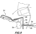
- Figures 6-9 illustrate various types of fasteners for use with the heat shield and heat shield assembly according to the invention.
- Figure 6 shows sutures or stitches 62 used to attach the tab 56 to sleeve 40, the tab and sleeve being sewn together.
- lacing filaments 64 engage both the tab 56 and the sleeve 40 to effect attachment.
- the lacing filaments may be interlaced with the sleeve as shown or extend around the assembly.
- adhesive tape 66 extends around the sleeve 40 and the tab 56, while in Figure 5 , a mechanical fastener, for example, a rivet 68, is used to secure sleeve to tab.
- an aperture 70 positioned in tab 56 receives wires 34 to effect attachment to the heat shield 54. It is understood that any of the various attachment fasteners shown may be used with any embodiment of the heat shield to form the heat shield assembly according to the invention.
- FIG 10 shows another embodiment of a heat shield assembly 72 wherein the shroud 12 is attached to the protective sleeve 40 by a tether 74.
- Tether 74 is a flexible filament and could, for example, comprise a deformable wire or a cord. Attachment of the tether to the sleeve may be effected by any of the above identified attachment methods.
- FIG 11 illustrates another embodiment of a heat shield assembly 76 wherein the means for attaching the shroud 12 to the sleeve 40 comprises a filamentary loop 78.
- Loop 78 preferably comprises a resilient wire and is attachable to the sleeve 40 as shown or the wires 34 comprising harness 30 by any of the means described above.
- Shroud 12 has an aperture 80 that receives loop 78 for attachment of the shroud to the sleeve.
- the shroud is slidably movable along the loop for movement from a position spaced from the item to a position in which the shroud covers the item.
- the means for attaching the shroud 12 comprises a hinge 84.
- a first hinge portion 86 is attached to the shroud and a second hinge portion 88 is attachable to the wiring harness, for example, the protective sleeve component.
- Hinge 84 may have locking features to hold it in a particular position, or it may be biased to force the shroud into engagement with an item.
- hinge 84 effects pivoting of the shroud 12 from a position spaced from the item 24 (shown in solid line) to a position in which the shroud covers the item, shown in phantom line .
- Heat shields and heat shield assemblies according to the invention provide numerous advantages over conventional heat shields currently in use.
- the shield becomes an integral part of a subassembly for a vehicle. This simplifies logistics and production, as fewer parts must be kept on inventory, shipped, handled and assembled into the vehicle. This saves time and reduces costs at the vehicle assembly stage of manufacture.
Landscapes
- Engineering & Computer Science (AREA)
- Mechanical Engineering (AREA)
- Physics & Mathematics (AREA)
- Acoustics & Sound (AREA)
- Chemical & Material Sciences (AREA)
- Combustion & Propulsion (AREA)
- General Engineering & Computer Science (AREA)
- Details Of Indoor Wiring (AREA)
- Installation Of Indoor Wiring (AREA)
Abstract
Description
- This invention relates to shielding for use in automotive engine compartments for the protection of electrical components from radiant heat transfer.
- Sensors used in automotive applications, such as engine knock sensors and oxygen sensors, which provide data to control engine operation and performance, are often mounted within the engine compartment of a vehicle or directly on the engine where they are subject to a harsh physical environment, including intense radiant heat. In view of the harsh enviroment, it is advantageous to cover the relatively delicate sensors with a flexible, protective heat shield which can reflect radiant heat and prevent heat transfer to the component.
- While important to ensure protection of the sensors for proper engine operation, the design of the heat shield is often neglected and not properly integrated into the overall design of the vehicle and its sub-assemblies. Component heat shields are typically designed at the last minute and become separate parts that add to the already substantial inventory of parts for a vehicle. As separate parts, the heat shields are handled individually during vehicle assembly, and must be properly positioned over the correct component in the proper sequence, thereby adding to assembly time and cost.
- There is clearly a need for a heat shield that is integrated in a vehicle sub-assembly and therefore need not be handled as a separate part by the vehicle manufacturer with respect to inventory and vehicle assembly.
- The invention concerns a heat shield adapted for use with an elongate electrical conductor to protect an item connected to the conductor. The heat shield comprises a shroud for rejecting heat. The shroud is shaped so as to substantially cover the item. The shroud has a first attachment means for attachment of the shroud to the item. The shield has a second attachment means for attachment of the shroud to the conductor. The second attachment means facilitates positioning of the shroud with respect to the item.
- Preferably, the second attachment means comprises an elongated, flexible tab extending from the shroud. The tab is attachable to the conductor and has a bendable portion for relative movement of the shroud and the first attachment means from a position spaced from the item to a position in which the shroud covers the item. In one embodiment, the tab comprises a transverse fold line positioned between the fastener and the shroud, the tab being bendable about the fold line for facilitating the positional adjustment of the shroud.
- A fastener is used to attach the tab to the electrical conductor . By way of example, the fastener may comprise adhesive tape extendible around the tab and the electrical conductor, sutures extendible through the tab and engageable with the electrical conductor, lacing filaments extensible around the tab and the electrical conductor, or a rivet attaching the tab to a protective sleeve surrounding the conductor.
- The invention also encompasses an assembly engageable with an item for protecting the item from heat energy and providing an electrical connection thereto. The assembly comprises a wiring harness connectable to the item. A protective sleeve surrounds the harness, A shroud for rejecting heat is attached to the sleeve. The shroud is shaped so as to substantially cover the item. A clip is used to attach the shroud to the item. An elongated, flexible tab extends from the shroud and is attached to the sleeve of the harness. The tab has a bendable portion for relative movement of the shroud from a position spaced from the item to a position in which the shroud covers the item. The wiring harness preferably has a connector at one end connectable to the item.
-
-
Figure 1 is a partial sectional perspective view of a heat shield according to the invention; -
Figure 2 is a longitudinal sectional view of a heat shield assembly according to the invention; -
Figure 3 is a cross-sectional view taken at line 3-3 ofFigure 2 ; -
Figure 4 is a partial sectional perspective view of an alternate embodiment of a heat shield according to the invention; -
Figure 5 is a longitudinal sectional view of an alternate embodiment of a heat shield assembly according to the invention; -
Figures 6-9 are partial sectional views showing details of various embodiments of the heat shield assembly according to the invention; -
Figure 10 is a perspective view of an alternate embodiment of a heat shield assembly according to the invention; -
Figure 11 is a perspective view of another embodiment of a heat shield assembly; -
Figure 12 is a perspective view of yet another embodiment of a heat shield; and -
Figure 13 is a partial sectional view of the heat shield ofFigure 12 shown in an assembly. -
Figure 1 shows aheat shield 10 according to the invention.Heat shield 10 comprises ashroud 12 shaped as needed to substantially cover an item to be protected from radiant heat or isolated from other items because it emits radiant heat. Preferably,shroud 12 comprises an outwardly facingreflective layer 14, an inwardly facingreflective layer 16, and aninsulating layer 18 positioned between thereflective layers reflective layers insulating layer 18 is preferably a non-woven polyester felt, although other non-conducting heat resistant materials such as glass fiber mats are also feasible. -
Heat shield 10 includes a first attachment means, preferably in the form of aclip 20, adapted to engage an item and hold the shield in position thereon.Clip 20 is preferably made from a flexible, resilient material such as a spring steel or a polymer, and has a plurality ofresilient arms 22 that are resiliently engageable with the item to whichheat shield 10 is to be attached. As shown inFigure 3 , thearms 22 may be positioned in spaced apart facing relation as appropriate to accommodate aparticular item 24, for example, an engine knock sensor or an automotive oxygen sensor.Clip 20 is preferably attached on the inwardly facing surface ofshroud 12 by afastener 26, shown inFigure 1 . - For shrouds that are formed of flexible material, the
clip 20 also serves to stiffen the shroud and prevent it from deforming and contacting the item covered by the heat shield. -
Heat shield 10 also includes a second attachment means, preferably in the form of an elongated,flexible tab 28.Tab 28 extends fromshroud 12 and is preferably formed from the same material as the shroud. As shown inFigure 2 ,tab 28 is used to attach theheat shield 10 to awiring harness 30 and thereby form aheat shield assembly 32. Thewiring harness 30 provides an electrical connection to theitem 24 and includes, therefore, electrical conductors such aswires 34 attached to aconnector 36 compatible with areceptacle 38 on theitem 24. Preferably, aprotective sleeve 40 surrounds thewires 34, and thetab 28 may be attached to it using afastener 42 as shown, or attached directly to thewires 34 as described below. - As illustrated in
Figure 2 ,tab 28 is flexible and elongated and preferably includes one or morebendable portions 44 for relative movement of theshroud 12 from a position spaced from the item 24 (shown in solid line) to a position in which the shroud covers the item (shown in phantom line). Preferably, thebendable portions 44 are defined bytransverse fold lines 46 positioned betweenfastener 42 andshroud 12. In the embodiment shown inFigure 2 , two transverse fold lines, 46a and 46b, define afirst fold 48 positioned adjacent to the shroud, asecond fold 50 positioned between the fold lines and extending in the opposite direction tofirst fold 48 and athird fold 52 extending from thesecond fold line 46b in an opposite direction to thesecond fold 50. Thethird fold 52 is attached tosleeve 40 byfastener 42, The bendable characteristic oftab 28 allows it to fold and unfold in the manner of a pleat or accordion fold to cover and uncover theitem 24. -
Figure 4 shows anotherembodiment 54 of a heat shield according to the invention.Heat shield 54 differs from theembodiment 10 in thattab 56 is shorter thantab 28 shown inFigures 1 and2 . As shown inFigure 5 ,tab 56 is elongated, flexible and has abendable portion 58 for relative movement of theshroud 12 from a position spaced from the item 24 (shown in solid line) to a position in which the shroud covers the item (shown in phantom line). Again, the tab may be attached to awiring harness 30 by afastener 42 to form aheat shield assembly 60. -
Figures 6-9 illustrate various types of fasteners for use with the heat shield and heat shield assembly according to the invention.Figure 6 shows sutures orstitches 62 used to attach thetab 56 to sleeve 40, the tab and sleeve being sewn together. InFigure 7 , lacingfilaments 64 engage both thetab 56 and thesleeve 40 to effect attachment. The lacing filaments may be interlaced with the sleeve as shown or extend around the assembly, As shown inFigure 8 ,adhesive tape 66 extends around thesleeve 40 and thetab 56, while inFigure 5 , a mechanical fastener, for example, arivet 68, is used to secure sleeve to tab. InFigure 9 , anaperture 70 positioned intab 56 receiveswires 34 to effect attachment to theheat shield 54. It is understood that any of the various attachment fasteners shown may be used with any embodiment of the heat shield to form the heat shield assembly according to the invention. -
Figure 10 shows another embodiment of aheat shield assembly 72 wherein theshroud 12 is attached to theprotective sleeve 40 by atether 74.Tether 74 is a flexible filament and could, for example, comprise a deformable wire or a cord. Attachment of the tether to the sleeve may be effected by any of the above identified attachment methods. -
Figure 11 illustrates another embodiment of aheat shield assembly 76 wherein the means for attaching theshroud 12 to thesleeve 40 comprises afilamentary loop 78.Loop 78 preferably comprises a resilient wire and is attachable to thesleeve 40 as shown or thewires 34 comprisingharness 30 by any of the means described above.Shroud 12 has anaperture 80 that receivesloop 78 for attachment of the shroud to the sleeve. The shroud is slidably movable along the loop for movement from a position spaced from the item to a position in which the shroud covers the item. - In another embodiment of the
heat shield 82, the means for attaching theshroud 12 comprises ahinge 84. Afirst hinge portion 86 is attached to the shroud and asecond hinge portion 88 is attachable to the wiring harness, for example, the protective sleeve component.Hinge 84 may have locking features to hold it in a particular position, or it may be biased to force the shroud into engagement with an item. - As best shown in
Figure 13 , hinge 84 effects pivoting of theshroud 12 from a position spaced from the item 24 (shown in solid line) to a position in which the shroud covers the item, shown in phantom line . - Heat shields and heat shield assemblies according to the invention provide numerous advantages over conventional heat shields currently in use. By forming a heat shield that is readily combinable with a wiring harness, the shield becomes an integral part of a subassembly for a vehicle. This simplifies logistics and production, as fewer parts must be kept on inventory, shipped, handled and assembled into the vehicle. This saves time and reduces costs at the vehicle assembly stage of manufacture.
Claims (15)
- A heat shield (10; 54; 72; 76; 82) adapted for use with an elongated electrical conductor (30, 34) to protect an item (24) connected to said conductor, said heat shield, comprising:a shroud (12) for rejecting heat, said shroud being shaped so as to substantially cover said item;a first attachment means (20) for attachment of said shroud to said item; anda second attachment means (28, 56; 74; 78; 84 - 88) for attachment of said shroud to said conductor (30, 34) for positioning said shroud with respect to said item,characterised in that said first attachment means comprises a clip (20) which includes a plurality of resilient arms (22) resiliently engageable with said item.
- A heat shield according to claim 1, wherein said second attachment means comprises a tether (74) having a first portion attachable to said conductor (30, 34) and a second portion attached to said shroud (12).
- A heat shield according to claim 1, wherein said second attachment means comprises a filamentary loop (78) attachable to said conductor (30, 34), said shroud (12) having an aperture (80) therethrough for receiving said loop, said shroud being slidably movable along said loop for movement from a position spaced from said item (24) to a position in which said shroud covers said item.
- A heat shield according to claim 3, wherein said filamentary loop (78) comprises a resilient wire.
- A heat shield according to claim 1, wherein said second attachment means (84 - 88) comprises a hinge (84) having a first hinge member (88) attachable to said conductor (30, 34) and a second hinge member (86) attached to said shroud (12), said hinge being for effecting pivoting of said shroud from a position spaced from said item (24) to a position in which said shroud covers said item.
- A heat shield according to claim 1, wherein said shroud (12) comprises a heat reflecting surface, such as of a metal foil (14, 16) for reflecting radiant heat energy.
- A heat shield according to claim 6, wherein said shroud (12) comprises an insulating layer (18) positioned between said first attachment means (20) and said heat reflecting surface (14), said insulating layer for preventing conductive heat transfer to and from said item (24).
- A heat shield according to claim 1, wherein said shroud (12) comprises an insulating layer (18) for preventing conductive heat transfer to and from said item (24).
- A heat shield according to claim 1, wherein said clip (20) comprises two of said resilient arms (22) positioned in spaced apart relation facing one another.
- An assembly engageable with an item (24) for protecting said item from heat energy and providing an electrical connection thereto, said assembly comprising:a wiring harness (30) connectable to said item;a shroud (12) for rejecting heat, said shroud being shaped so as to substantially cover said item;a clip (20) adapted to attach said shroud (12) to said item; andsecond attachment means (28; 56; 75; 84 - 88) configured differently to said clip (20) for attaching said shroud to said wiring harness.
- An assembly according to claim 10, further comprising a protective sleeve (40) surrounding said harness (30), said second attachment means being attached to said protective sleeve.
- An assembly according to claim 11, wherein said second attachment means comprises a tether (74) having a first portion attached to said protective sleeve (40) and a second portion attached to said shroud (12).
- An assembly according to claim 12, wherein said second attachment means comprises a filamentary loop (78), said loop being attached to said sleeve (40), said shroud (12) having an aperture (80) therethrough for receiving said loop, said shroud being slidably movable along said loop for movement from a position spaced from said item (24) to a position in which said shroud covers said item.
- An assembly according to claim 13, wherein said loop (78) comprises a resilient wire.
- An assembly according to claim 11, wherein said second attachment means comprises a hinge (84) having a first hinge member (88) attached to said protective sleeve (40) and a second hinge member (86) attached to said shroud (12), said hinge being for effecting pivoting of said shroud from a position spaced from said item (24) to a position in which said shroud covers said item.
Applications Claiming Priority (2)
| Application Number | Priority Date | Filing Date | Title |
|---|---|---|---|
| US10/956,550 US7216622B2 (en) | 2004-10-01 | 2004-10-01 | Wiring harness with integrated component heat shield |
| EP05805722A EP1794427B1 (en) | 2004-10-01 | 2005-10-03 | Wiring harness with integrated component heat shield |
Related Parent Applications (2)
| Application Number | Title | Priority Date | Filing Date |
|---|---|---|---|
| EP05805722.5 Division | 2005-10-03 | ||
| EP05805722A Division-Into EP1794427B1 (en) | 2004-10-01 | 2005-10-03 | Wiring harness with integrated component heat shield |
Publications (2)
| Publication Number | Publication Date |
|---|---|
| EP2461002A1 true EP2461002A1 (en) | 2012-06-06 |
| EP2461002B1 EP2461002B1 (en) | 2013-08-28 |
Family
ID=36124313
Family Applications (2)
| Application Number | Title | Priority Date | Filing Date |
|---|---|---|---|
| EP12157962.7A Expired - Lifetime EP2461002B1 (en) | 2004-10-01 | 2005-10-03 | Heat shield |
| EP05805722A Expired - Lifetime EP1794427B1 (en) | 2004-10-01 | 2005-10-03 | Wiring harness with integrated component heat shield |
Family Applications After (1)
| Application Number | Title | Priority Date | Filing Date |
|---|---|---|---|
| EP05805722A Expired - Lifetime EP1794427B1 (en) | 2004-10-01 | 2005-10-03 | Wiring harness with integrated component heat shield |
Country Status (8)
| Country | Link |
|---|---|
| US (1) | US7216622B2 (en) |
| EP (2) | EP2461002B1 (en) |
| JP (2) | JP5095406B2 (en) |
| KR (1) | KR20070083788A (en) |
| CN (1) | CN101065563A (en) |
| CA (1) | CA2582013A1 (en) |
| MX (1) | MX2007003937A (en) |
| WO (1) | WO2006039628A2 (en) |
Families Citing this family (15)
| Publication number | Priority date | Publication date | Assignee | Title |
|---|---|---|---|---|
| DE10357175B4 (en) * | 2003-12-06 | 2006-03-16 | Mtu Friedrichshafen Gmbh | Base plate for a crankcase |
| JP4296502B2 (en) * | 2004-10-01 | 2009-07-15 | 豊田合成株式会社 | Engine cover mounting structure |
| DE102006026446B4 (en) * | 2006-06-07 | 2009-02-26 | Pierburg Gmbh | Cover for an actuator with a punched grid as a hinge |
| DE102006029087A1 (en) * | 2006-06-24 | 2008-01-03 | Elringklinger Ag | Structural component, in particular shielding in the form of a heat shield |
| GB2455740B (en) * | 2007-12-20 | 2012-06-13 | Nissan Motor Iberica Sa | Improvements in or relating to heat shields |
| FR2925404B1 (en) * | 2007-12-21 | 2010-04-02 | Peugeot Citroen Automobiles Sa | THERMAL SCREEN FOR HIGH-POSITION SPEED CONTROL IN A VEHICLE |
| GB2489472B (en) * | 2011-03-30 | 2015-05-20 | Nissan Motor Mfg Uk Ltd | Heat shield fastener cover |
| US8757215B2 (en) * | 2011-08-22 | 2014-06-24 | Federal-Mogul Powertrain, Inc. | Radially collapsible and expandable textile sleeve and method of construction thereof |
| JP6028279B2 (en) * | 2012-09-10 | 2016-11-16 | 矢崎総業株式会社 | Wire harness |
| DE202013006309U1 (en) * | 2013-07-11 | 2014-07-14 | Reinz-Dichtungs-Gmbh | heat shield |
| KR20160048143A (en) * | 2013-08-26 | 2016-05-03 | 페더럴-모걸 파워트레인, 인코포레이티드 | Wrappable multi-layer heat shield |
| CN104481691A (en) * | 2014-11-13 | 2015-04-01 | 重庆峰瑞塑料制品有限公司 | Gasoline engine hood |
| US9982579B2 (en) * | 2015-07-07 | 2018-05-29 | United Technologies Corporation | Thermally compliant heatshield |
| US10578013B2 (en) * | 2016-05-23 | 2020-03-03 | Ford Global Technologies, Llc | Bendable heat shield for simplified servicing of internal combustion engine |
| US10480440B2 (en) * | 2017-11-13 | 2019-11-19 | GM Global Technology Operations LLC | Particulate matter sensor heat cover |
Citations (5)
| Publication number | Priority date | Publication date | Assignee | Title |
|---|---|---|---|---|
| JPH04350979A (en) * | 1991-05-29 | 1992-12-04 | Fuji Electric Co Ltd | Lead wire for measurement of cryostat |
| US5403996A (en) * | 1994-02-25 | 1995-04-04 | Casco Products Corporation | Connector receptacle construction for electric cigar lighters |
| GB2322112A (en) * | 1997-02-17 | 1998-08-19 | Thomas Stewart Miller | Apparatus for warning ground personnel of impending aircraft start-up |
| US6415757B1 (en) * | 1998-04-22 | 2002-07-09 | Visteon Global Technologies, Inc. | Fluid-cooled heat shield for temperature sensitive automotive components |
| JP2002352896A (en) * | 2001-05-23 | 2002-12-06 | Sumitomo Wiring Syst Ltd | Connector protection cap |
Family Cites Families (6)
| Publication number | Priority date | Publication date | Assignee | Title |
|---|---|---|---|---|
| JPS5811864U (en) * | 1981-07-16 | 1983-01-25 | 住友電装株式会社 | Battery post terminal cover |
| JPH083137Y2 (en) * | 1990-12-14 | 1996-01-29 | 冨美雄 森川 | Cover sheet for wiring cords inside automobiles |
| SK282117B6 (en) * | 1993-12-18 | 2001-11-06 | Merck Patent Gesellschaft Mit Beschr�Nkter Haftung | DISTRIBUTION EQUIPMENT FOR PARTICULAR MATERIAL |
| JP2001272422A (en) * | 2000-03-27 | 2001-10-05 | Jeco Co Ltd | Vehicle current detector |
| JP2002017033A (en) * | 2000-06-28 | 2002-01-18 | Sumitomo Wiring Syst Ltd | Terminal protection cap |
| US20060054763A1 (en) * | 2004-09-16 | 2006-03-16 | Federal-Mogul World Wide, Inc. | Heat shield positioning assembly |
-
2004
- 2004-10-01 US US10/956,550 patent/US7216622B2/en not_active Expired - Lifetime
-
2005
- 2005-10-03 EP EP12157962.7A patent/EP2461002B1/en not_active Expired - Lifetime
- 2005-10-03 JP JP2007534849A patent/JP5095406B2/en not_active Expired - Fee Related
- 2005-10-03 WO PCT/US2005/035440 patent/WO2006039628A2/en not_active Ceased
- 2005-10-03 CA CA002582013A patent/CA2582013A1/en not_active Abandoned
- 2005-10-03 EP EP05805722A patent/EP1794427B1/en not_active Expired - Lifetime
- 2005-10-03 MX MX2007003937A patent/MX2007003937A/en not_active Application Discontinuation
- 2005-10-03 KR KR1020077009341A patent/KR20070083788A/en not_active Withdrawn
- 2005-10-03 CN CNA2005800407337A patent/CN101065563A/en active Pending
-
2012
- 2012-07-19 JP JP2012160294A patent/JP5490856B2/en not_active Expired - Lifetime
Patent Citations (5)
| Publication number | Priority date | Publication date | Assignee | Title |
|---|---|---|---|---|
| JPH04350979A (en) * | 1991-05-29 | 1992-12-04 | Fuji Electric Co Ltd | Lead wire for measurement of cryostat |
| US5403996A (en) * | 1994-02-25 | 1995-04-04 | Casco Products Corporation | Connector receptacle construction for electric cigar lighters |
| GB2322112A (en) * | 1997-02-17 | 1998-08-19 | Thomas Stewart Miller | Apparatus for warning ground personnel of impending aircraft start-up |
| US6415757B1 (en) * | 1998-04-22 | 2002-07-09 | Visteon Global Technologies, Inc. | Fluid-cooled heat shield for temperature sensitive automotive components |
| JP2002352896A (en) * | 2001-05-23 | 2002-12-06 | Sumitomo Wiring Syst Ltd | Connector protection cap |
Also Published As
| Publication number | Publication date |
|---|---|
| MX2007003937A (en) | 2007-06-07 |
| JP5490856B2 (en) | 2014-05-14 |
| JP5095406B2 (en) | 2012-12-12 |
| CA2582013A1 (en) | 2006-04-13 |
| EP2461002B1 (en) | 2013-08-28 |
| EP1794427A2 (en) | 2007-06-13 |
| EP1794427B1 (en) | 2012-09-26 |
| WO2006039628A3 (en) | 2006-07-13 |
| JP2008514509A (en) | 2008-05-08 |
| WO2006039628A2 (en) | 2006-04-13 |
| US20060070598A1 (en) | 2006-04-06 |
| CN101065563A (en) | 2007-10-31 |
| KR20070083788A (en) | 2007-08-24 |
| US7216622B2 (en) | 2007-05-15 |
| JP2012217335A (en) | 2012-11-08 |
| EP1794427A4 (en) | 2010-01-06 |
Similar Documents
| Publication | Publication Date | Title |
|---|---|---|
| JP5490856B2 (en) | Heat shield and assembly including the same | |
| US11525711B2 (en) | Protection shield positioning assembly and positioning device therefore and method of use | |
| US8887687B2 (en) | Heat shield having locating and retention features | |
| JP6847918B2 (en) | Thermal sleeves with reflective disposition members, assemblies with them, and how to build them | |
| CN108141022B (en) | Thermal sleeve with reflective positioning member, assembly thereof and method of construction thereof | |
| KR20070063518A (en) | Heat shield positioning assembly | |
| EP0742947B1 (en) | Improvements in and relating to textile braids | |
| WO1995021451A9 (en) | Improvements in and relating to textile braids | |
| EP0998000A2 (en) | Modular wire harness protector | |
| KR200251403Y1 (en) | Clip For Fixing The Wire Harness | |
| US20230117503A1 (en) | Protection shield positioning assembly and positioning device therefore and method of use | |
| JP2002293203A (en) | Armor structure for wire harness | |
| KR20090043338A (en) | Connector rear cover mounting structure | |
| WO2024097914A1 (en) | Self-locating, thermal, flame protection sleeve and associated methods | |
| CN121713344A (en) | Wire harness fixing components | |
| KR200300798Y1 (en) | wire harness fix clip | |
| JP2026029082A (en) | Protector unit and wire harness | |
| JP2002078140A (en) | Protector | |
| JPH106882A (en) | Wiring equipment for vehicles |
Legal Events
| Date | Code | Title | Description |
|---|---|---|---|
| PUAI | Public reference made under article 153(3) epc to a published international application that has entered the european phase |
Free format text: ORIGINAL CODE: 0009012 |
|
| AC | Divisional application: reference to earlier application |
Ref document number: 1794427 Country of ref document: EP Kind code of ref document: P |
|
| AK | Designated contracting states |
Kind code of ref document: A1 Designated state(s): DE ES FR GB IT |
|
| RIN1 | Information on inventor provided before grant (corrected) |
Inventor name: TEAL, JIMMY, E. Inventor name: RUBEL, WILLIAM, T., JR. Inventor name: JAMES, BENJAMIN, B. Inventor name: MARKS, PHILIP, E. |
|
| 17P | Request for examination filed |
Effective date: 20121109 |
|
| GRAP | Despatch of communication of intention to grant a patent |
Free format text: ORIGINAL CODE: EPIDOSNIGR1 |
|
| RIC1 | Information provided on ipc code assigned before grant |
Ipc: F02F 7/00 20060101ALI20130318BHEP Ipc: B60R 13/08 20060101ALI20130318BHEP Ipc: F02B 77/00 20060101AFI20130318BHEP |
|
| INTG | Intention to grant announced |
Effective date: 20130422 |
|
| GRAS | Grant fee paid |
Free format text: ORIGINAL CODE: EPIDOSNIGR3 |
|
| GRAA | (expected) grant |
Free format text: ORIGINAL CODE: 0009210 |
|
| AC | Divisional application: reference to earlier application |
Ref document number: 1794427 Country of ref document: EP Kind code of ref document: P |
|
| AK | Designated contracting states |
Kind code of ref document: B1 Designated state(s): DE ES FR GB IT |
|
| REG | Reference to a national code |
Ref country code: GB Ref legal event code: FG4D |
|
| REG | Reference to a national code |
Ref country code: DE Ref legal event code: R096 Ref document number: 602005041085 Country of ref document: DE Effective date: 20131024 |
|
| PG25 | Lapsed in a contracting state [announced via postgrant information from national office to epo] |
Ref country code: ES Free format text: LAPSE BECAUSE OF FAILURE TO SUBMIT A TRANSLATION OF THE DESCRIPTION OR TO PAY THE FEE WITHIN THE PRESCRIBED TIME-LIMIT Effective date: 20130828 |
|
| REG | Reference to a national code |
Ref country code: DE Ref legal event code: R097 Ref document number: 602005041085 Country of ref document: DE |
|
| PLBE | No opposition filed within time limit |
Free format text: ORIGINAL CODE: 0009261 |
|
| STAA | Information on the status of an ep patent application or granted ep patent |
Free format text: STATUS: NO OPPOSITION FILED WITHIN TIME LIMIT |
|
| 26N | No opposition filed |
Effective date: 20140530 |
|
| REG | Reference to a national code |
Ref country code: DE Ref legal event code: R097 Ref document number: 602005041085 Country of ref document: DE Effective date: 20140530 |
|
| REG | Reference to a national code |
Ref country code: FR Ref legal event code: PLFP Year of fee payment: 11 |
|
| REG | Reference to a national code |
Ref country code: FR Ref legal event code: PLFP Year of fee payment: 12 |
|
| REG | Reference to a national code |
Ref country code: FR Ref legal event code: PLFP Year of fee payment: 13 |
|
| REG | Reference to a national code |
Ref country code: FR Ref legal event code: PLFP Year of fee payment: 14 |
|
| PGFP | Annual fee paid to national office [announced via postgrant information from national office to epo] |
Ref country code: GB Payment date: 20180926 Year of fee payment: 14 |
|
| GBPC | Gb: european patent ceased through non-payment of renewal fee |
Effective date: 20191003 |
|
| PG25 | Lapsed in a contracting state [announced via postgrant information from national office to epo] |
Ref country code: GB Free format text: LAPSE BECAUSE OF NON-PAYMENT OF DUE FEES Effective date: 20191003 |
|
| PGFP | Annual fee paid to national office [announced via postgrant information from national office to epo] |
Ref country code: IT Payment date: 20201015 Year of fee payment: 16 |
|
| PG25 | Lapsed in a contracting state [announced via postgrant information from national office to epo] |
Ref country code: IT Free format text: LAPSE BECAUSE OF NON-PAYMENT OF DUE FEES Effective date: 20211003 |
|
| P01 | Opt-out of the competence of the unified patent court (upc) registered |
Effective date: 20230528 |
|
| PGFP | Annual fee paid to national office [announced via postgrant information from national office to epo] |
Ref country code: FR Payment date: 20240919 Year of fee payment: 20 |
|
| PGFP | Annual fee paid to national office [announced via postgrant information from national office to epo] |
Ref country code: DE Payment date: 20240919 Year of fee payment: 20 |
|
| REG | Reference to a national code |
Ref country code: DE Ref legal event code: R071 Ref document number: 602005041085 Country of ref document: DE |
|
| REG | Reference to a national code |
Ref country code: DE Ref legal event code: R081 Ref document number: 602005041085 Country of ref document: DE Owner name: SYSTEMS PROTECTION GROUP US LLC (N.D.GES.D. ST, US Free format text: FORMER OWNER: FEDERAL-MOGUL POWERTRAIN, INC., SOUTHFIELD, MICH., US |