EP2460693A1 - Roof clip for attaching accessories to the panels of vehicles - Google Patents
Roof clip for attaching accessories to the panels of vehicles Download PDFInfo
- Publication number
- EP2460693A1 EP2460693A1 EP10803930A EP10803930A EP2460693A1 EP 2460693 A1 EP2460693 A1 EP 2460693A1 EP 10803930 A EP10803930 A EP 10803930A EP 10803930 A EP10803930 A EP 10803930A EP 2460693 A1 EP2460693 A1 EP 2460693A1
- Authority
- EP
- European Patent Office
- Prior art keywords
- clip
- previous
- roof
- wings
- base
- Prior art date
- Legal status (The legal status is an assumption and is not a legal conclusion. Google has not performed a legal analysis and makes no representation as to the accuracy of the status listed.)
- Granted
Links
Images


Classifications
-
- B—PERFORMING OPERATIONS; TRANSPORTING
- B60—VEHICLES IN GENERAL
- B60R—VEHICLES, VEHICLE FITTINGS, OR VEHICLE PARTS, NOT OTHERWISE PROVIDED FOR
- B60R13/00—Elements for body-finishing, identifying, or decorating; Arrangements or adaptations for advertising purposes
- B60R13/02—Internal Trim mouldings ; Internal Ledges; Wall liners for passenger compartments; Roof liners
-
- B—PERFORMING OPERATIONS; TRANSPORTING
- B60—VEHICLES IN GENERAL
- B60R—VEHICLES, VEHICLE FITTINGS, OR VEHICLE PARTS, NOT OTHERWISE PROVIDED FOR
- B60R13/00—Elements for body-finishing, identifying, or decorating; Arrangements or adaptations for advertising purposes
- B60R13/02—Internal Trim mouldings ; Internal Ledges; Wall liners for passenger compartments; Roof liners
- B60R13/0206—Arrangements of fasteners and clips specially adapted for attaching inner vehicle liners or mouldings
-
- F—MECHANICAL ENGINEERING; LIGHTING; HEATING; WEAPONS; BLASTING
- F16—ENGINEERING ELEMENTS AND UNITS; GENERAL MEASURES FOR PRODUCING AND MAINTAINING EFFECTIVE FUNCTIONING OF MACHINES OR INSTALLATIONS; THERMAL INSULATION IN GENERAL
- F16B—DEVICES FOR FASTENING OR SECURING CONSTRUCTIONAL ELEMENTS OR MACHINE PARTS TOGETHER, e.g. NAILS, BOLTS, CIRCLIPS, CLAMPS, CLIPS OR WEDGES; JOINTS OR JOINTING
- F16B37/00—Nuts or like thread-engaging members
- F16B37/02—Nuts or like thread-engaging members made of thin sheet material
-
- F—MECHANICAL ENGINEERING; LIGHTING; HEATING; WEAPONS; BLASTING
- F16—ENGINEERING ELEMENTS AND UNITS; GENERAL MEASURES FOR PRODUCING AND MAINTAINING EFFECTIVE FUNCTIONING OF MACHINES OR INSTALLATIONS; THERMAL INSULATION IN GENERAL
- F16B—DEVICES FOR FASTENING OR SECURING CONSTRUCTIONAL ELEMENTS OR MACHINE PARTS TOGETHER, e.g. NAILS, BOLTS, CIRCLIPS, CLAMPS, CLIPS OR WEDGES; JOINTS OR JOINTING
- F16B37/00—Nuts or like thread-engaging members
- F16B37/04—Devices for fastening nuts to surfaces, e.g. sheets, plates
-
- F—MECHANICAL ENGINEERING; LIGHTING; HEATING; WEAPONS; BLASTING
- F16—ENGINEERING ELEMENTS AND UNITS; GENERAL MEASURES FOR PRODUCING AND MAINTAINING EFFECTIVE FUNCTIONING OF MACHINES OR INSTALLATIONS; THERMAL INSULATION IN GENERAL
- F16B—DEVICES FOR FASTENING OR SECURING CONSTRUCTIONAL ELEMENTS OR MACHINE PARTS TOGETHER, e.g. NAILS, BOLTS, CIRCLIPS, CLAMPS, CLIPS OR WEDGES; JOINTS OR JOINTING
- F16B37/00—Nuts or like thread-engaging members
- F16B37/04—Devices for fastening nuts to surfaces, e.g. sheets, plates
- F16B37/041—Releasable devices
- F16B37/043—Releasable devices with snap action
Definitions
- the object of the present invention pertains to a roof clip of the type used in the automobile industry for securing accessories to the panels of vehicles, wherein the piece has been optimized in order to obtain low insertion force and has been especially designed for the modular assembly system of the roof while providing at the same time a strong fastening, with high extraction force once the clip is assembled on the application and with the possibility of disassembling the piece from the panel, thereby keeping undesired noises from occurring in the clip itself whenever it receives the expected force and permitting the adaptation of the clip to a range of thicknesses of said panel owing to its constructional shape.
- Roof clips are known for attaching accessories to the panels of vehicles in the automobile industry.
- One of their peculiarities is that due to working reasons they are assembled in slots provided in said panels so that the only access to them is gained from the inner side of the vehicle, which inner side is exterior to said insertion slot.
- Said type of clips are provided with a portion that can be inserted into said slot and that is usually is provided with flexible wings which expand and act as abutments thereby preventing the inverse travel of the clip when the surface of the panel is fully pierced through.
- Said clips both in the variants thereof and in the present invention, which depending on the particular embodiment are provided with a thread and an orifice for the use of a screw, feature a base with a threading element, it being either single-threaded or multi-threaded, such as for instance a threaded cylinder that rises and moves into the inner area of the panel, that is, where the screw is inserted.
- Spanish patent ES2107378 develops a clip of this type that is provided with a base having side wings, a threaded orifice for the passage of a screw and arms and flaps that altogether converge in their elongation towards the inside of the panel, said flaps being responsible for performing the retention of the clip in the panel.
- the present invention goes one step further as it develops an approximately inverted "V"-shaped overall configuration having at its vertex a head or central surface, devoid of independent arms, that supports, in a configuration inverse to the one used in the above-mentioned patent, the fastening flaps in the panel.
- said flaps give continuity to said surface, which is located at the furthest area from the base of the panel.
- the present invention develops a clip intended to be secured by means of a screw. It is precisely another one of the main objects of the present invention to increase the tightening torque for the attachment of accessories in this type of clips through the incorporation of a threaded tube or the use of a double thread.
- the present invention describes a roof clip of the type used for attaching accessories to the panels of vehicles, wherein once the accessory has previously been assembled on the modular system of the roof and secured to the clip by means of a screw, both are inserted into a slot made in said panels.
- the wings for retention to the panels are disposed from an upper surface attached to the intermediate base by means of arms.
- Said upper surface with an overall inverted "V"-shaped configuration can be flat or blunt, feature a narrow width and, depending on the needs of the application, it can incorporate a drill or reinforcement intended to decrease the insertion force or increase the extraction force, respectively.
- the panel retention wings feature a progressive entry into the panel thanks to a progressive change in their inclination or an intermediate folding. Locking of the clip in the panel is obtained via either retention surfaces located at the end of the wings or a retention fold. Disassembling of the clip is possible by closing the retention wings thanks to flanges provided in said wings.
- the intermediate folding and/or the progressive change of inclination of the retention wings can incorporate, if need be, reinforcements for avoiding the premature deformation thereof when the extraction force is applied.
- the progressive and smooth lateral shape of the arms attaching the upper surface to the intermediate base facilitates correct alignment and subsequent insertion into the panel slot thereby reducing the insertion force required.
- the intermediate base has at the side elongations thereof respective wings transversally extending with respect to the clip, which wings in turn split into wings forming a "V" with the ends thereof located on a higher plane than that of the clip and featuring protuberances.
- Such configuration provides elasticity reserve to the assembly and prevents the occurrence of undesired noises caused by the vehicle vibrations thanks to the occasional and rounded contact of the protuberances, which are devoid of sharp edges that might damage the panel.
- the contact surfaces of the clip with the exterior portion of the panel lie at an extended distance from the center of the clip, both longitudinally and transversally speaking.
- said intermediate base may be provided with a step with respect to the plane of said wings.
- Some of such wings are provided with flanges for contact with the panel, these flanges have rounded ends. It is worth noting that in the preferred embodiment the folds provided at the ends of the retention wings prevent both the longitudinal displacement of the clip, particularly when force in such direction is applied on the levers, and the damage of the panel if there appeared any sharp edges.
- the intermediate base is provided with slots for the engagement of the rods securing the accessories to be installed and notches located in the proximity of the center of the clip permitting the folding of respective centering flanges that secure the lower base, thereby ensuring that the respective orifices for passage of the fixing screw are correctly aligned.
- the clip of invention includes an orifice, at the lower base, and another orifice with a threaded tube or with a single-threaded helical thread at the intermediate base.
- Such configuration provides a stable and rigid supporting metal base during the tightening operation of the screw, this thus keeping the thread from directly resting on the plastic surface of the accessory, which increases the tightening torque to be applied on the clip-accessory engagement.
- this double base system permits to provide some embodiments with respective double threads, one at either base, these being suitably spaced apart so that they can adequately adapt to the passage of the screw that is being used.
- the clip is easily positioned and assembled thanks to its approximately inverted "V" shape with a central surface that facilitates its alignment and insertion into the panel in combination with the progressive entries of the retention wings and the also progressive and smooth lateral external shape of the arms connecting the upper surface with the intermediate base.
- the clip is highly stable thanks to the fact that in its configuration there exist no elements causing friction with each other or free ends which may vibrate and/or interact with adjacent elements, thereby making noises, and also thanks to the fact that the flexible support legs of the wings permit a correct adaptation of the clip to a range of thicknesses of the panel so that the final insertion force can be reduced.
- the clip is of the dismountable type, upon installation, thanks to having disassembly flanges that facilitate extraction thereof.
- the present invention comprises a roof clip of the type used for attaching accessories to the panels of vehicles and inserted slots made in said panels, wherein once the clip is assembled on the modular system of the roof, along with the accessory thereof, and secured by means of a screw, the entire modular system is installed on the roof panel, which panel is provided with a base (2) having a threaded orifice, slots (16) at said base (2) for the engagement with the positioning elements of the accessory to be installed with the clip (1), it being provided with fastening wings (11) of the clip (1) to the vehicle panel thanks to a contact surface (12) with said panel, the invention being also provided with flanges (13) for extracting said clip from said panel, wherein there has been perfomed the overlapping of a lower base (3) with said intermediate base (2) while keeping aligned the thread (5) of said intermediate base (2) and the lower orifice (18) of said lower base (3).
- bases (2 and 3) are obtained, as seen in the figures accompanying the invention, thanks to the overlapping of said lower base (3) underneath the intermediate base (2) resulting from folding and forming the conical body of the clip with an upper surface (14), blunt and narrow, or approximately flat, depending on each actual embodiment, from which arms (10) attaching said surface to said bases (2 and 3) and descending side wings (11) extend.
- Said side wings (11) permit, thanks to a fold made towards the interior of the clip, a support and contact surface (12) of said wings (11) against the edges of the orifice or slot made in the panel. Said contact or abutment keeps the clip (1) from exiting said slot panel.
- the side wings (11) feature elbowed side surfaces (24). Said surfaces are subdivided into two portions, a first portion (27) located at the area adjacent to the vertex of the clip (1), the surface (14), which is the surface having the most inclination with respect to the vertical, and a second portion (28) that features an enlarged surface.
- the purpose of the above subdivided shape is on the one hand to provide a gradient suitable for diminishing the entry and insertion force into the panel and at the same time to provide said wing (11) with a suitable resistant working area.
- the contact and engagement surface (12) of said wings (11) with the panel comprises elongated flanges that are folded against the surface of said panel and secured to the ends of the elbowed side surfaces (24) of the wings (11).
- the extraction flanges (73) of the clip are disposed descending downwardly from said wings (11).
- said flanges (13) become attracted towards the center of the clip the engagement of the surfaces (12) is released and the clip is freed from the panel.
- the base of the clip (1) is provided at its side with a rebated surface (19).
- Said wings (11) and said flanges (13) can feature reinforcing deformations (22).
- the arms (10) securing said bases (2 and 3) to the surface (14), which is narrow in the preferred embodiment shown in figures 1 to 5 , have two portions, the first one (23) being adjacent to said surface (14) and having a higher degree of incline with respect to the vertical of the clip (1) in order to facilitate the entry thereof into the orifice of the panel.
- the arms, if need be, (10) may be provided with reinforcements (25), for instance in the form of deformations of the surface thereof.
- the base (2) of the clip extends in the largest longitudinal direction in order to form transverse wings (7) that work against the panel on the face opposed to that of the surface (12) of said wings (11).
- transverse wings (7) that is intended to be brought into contact with the panel is provided with reliefs against friction with said panel in the form of support protuberances (26). Said protuberances or other similar type of formations are intended to avoid contact areas between the clip (1) and the sharp-edged panel, thereby diminishing the noise resulting from the friction between both.
- the side wings (11) feature an intermediate fold and/or a progressive change in the inclination of said wing, which can also incorporate reinforcements (22) in order to prevent the premature deformation thereof when the extraction force is applied.
- This clip (1) also incorporates a simple means for extraction from the panel slot, consisting in the presence of flanges (13) that extend into said side wings (11) and further extend from said engagement surface (12). Upon exertion of pressure on said flanges (13), the surface (12) and the wings (11) can be released from the edges of the panel slot, thereby freeing the clip (1).
- the lower base (3) is provided with fastening flanges (4) that are folded over the surface or intermediate base (2) into notches (17) made in the slots (16) of said base (2) of the clip.
- the slots (16) are intended to house the elements for fastening the accessories assembled with the clip (1).
- Said notches (17) are intended to have said flanges fitted into them, without plays, this resulting in a secure and stable fastening devoid of mutual side displacements of the surfaces or bases (3 and 2) prior to the screwing of the accessory to be fastened to the clip (1).
- the intermediate base (2) can feature at its side extensions of the longer longitudinal direction a step (6) located on a plane approximately identical to that of said lower base (3) and wings (7) transversally extending towards the longer longitudinal direction of the clip.
- These wings (7) can incorporate respective reinforcing flanges (8) that extend further in said transverse direction.
- This type of clip can incorporate a reinforcement (15) or a drill (15') on the flat surface (14), if required by the application, so that in case a reinforcement (15) is used the extraction force can be increased or, in case the drill (15') is used the insertion force can be diminished and the reliability in the manufacture of the clip itself can be improved.
- the conical shape of the central portion of the clip (1) facilitates the insertion thereof, but also the very structure of the clip (1) provided with a blunt surface, or approximately flat, or particularly narrow (14), from which extend said wings (11), that are provided with a progressive entry into the panels by way of a progressive change of inclination thereof, along with the also progressive external lateral shape of the arms attaching the upper blunt surface to the bases, all of which facilitates the correct alignment and subsequent insertion into the panel slot, helps assembling and considerably reduces the required insertion force.
- a notch (19) in said base of the clip (2) that is basically intended to permit the operation of the tool suitable for disassembling the clip, thereby facilitating access to the extraction flanges (13) of the clip.
- protuberances (26) for support or flexible flanges (8) on the wings (7) considerably reduces, as compared to the winged base configuration of Spanish patent ES2107378 , the final force required to insert the clip into the panel.
- FIG. 12 Another possible embodiment of the present invention is shown in figures 12 and 13.
- a lower base (3) and an intermediate base (2) that keeps aligned, for this configuration, a double thread given the fact that each base incorporates a single thread and they are conveniently spaced from each other so that each base can adequately adapt for passage of the screw that is in operation.
- an addition feature of this embodiment is that the wings (7) and the support flanges have been replaced by support wings, in an independent body (21), that are made of plastic material and are either integrated in the clip, directly injected in the clip or assembled under pressure and fitted into the flaps (20) provided in both bases.
- the very plastic piece ensures the engagement as a whole of the two bases and at the same time provides a low insertion force. It is to be noted the reduced weight of this embodiment since it incorporates two pieces made of plastic material.
- figure 14 it is represented a variation of the previous embodiment, since it incorporates a threaded tube at the intermediate base and an orifice at the lower base. With that it is achieved, like in the preferred embodiment of figures 1 to 5 , an increase of the tightening torque in those applications requiring it.
- said wings (7) and flanges (8) are formed by the overlapping of the lower base (3) and said intermediate base (2).
- the intermediate base (2) extends transversally in the larger longitudinal direction of the clip (1) in the form of flanges (8) that protrude from the body of said lower base (3).
- Figure 11 shows an application of the invention in which it is worth noting the reduced dimensions of the clip so that it can adapt to those situations in which the assembling space is reduced.
- figure 16 shows another possible embodiment of the invention.
- the upper surface (14) is blunt and provided with a drill (15').
- the side wings (11) are smooth and devoid of the reinforcements (22) present in other embodiments.
- the thread is formed through the overlapping of a lower base (3) and its intermediate base (2) that keeps aligned the lower orifice of said lower base and the thread (5) of said intermediate base (2) .
Landscapes
- Engineering & Computer Science (AREA)
- General Engineering & Computer Science (AREA)
- Mechanical Engineering (AREA)
- Connection Of Plates (AREA)
- Clamps And Clips (AREA)
Abstract
Description
- The object of the present invention pertains to a roof clip of the type used in the automobile industry for securing accessories to the panels of vehicles, wherein the piece has been optimized in order to obtain low insertion force and has been especially designed for the modular assembly system of the roof while providing at the same time a strong fastening, with high extraction force once the clip is assembled on the application and with the possibility of disassembling the piece from the panel, thereby keeping undesired noises from occurring in the clip itself whenever it receives the expected force and permitting the adaptation of the clip to a range of thicknesses of said panel owing to its constructional shape.
- Roof clips are known for attaching accessories to the panels of vehicles in the automobile industry. One of their peculiarities is that due to working reasons they are assembled in slots provided in said panels so that the only access to them is gained from the inner side of the vehicle, which inner side is exterior to said insertion slot.
- Said type of clips are provided with a portion that can be inserted into said slot and that is usually is provided with flexible wings which expand and act as abutments thereby preventing the inverse travel of the clip when the surface of the panel is fully pierced through. Said clips, both in the variants thereof and in the present invention, which depending on the particular embodiment are provided with a thread and an orifice for the use of a screw, feature a base with a threading element, it being either single-threaded or multi-threaded, such as for instance a threaded cylinder that rises and moves into the inner area of the panel, that is, where the screw is inserted.
- For instance, Spanish patent
ES2107378 - Generally speaking, it is safe to state that it is convenient to utilize clips having an overall conical configuration for facilitating the task cf their insertion in the installation slot or orifice made in the panel of the vehicle. The present invention goes one step further as it develops an approximately inverted "V"-shaped overall configuration having at its vertex a head or central surface, devoid of independent arms, that supports, in a configuration inverse to the one used in the above-mentioned patent, the fastening flaps in the panel. In the invention said flaps give continuity to said surface, which is located at the furthest area from the base of the panel.
- Our Spanish patent application n°
200900740 - Conversely, the present invention develops a clip intended to be secured by means of a screw. It is precisely another one of the main objects of the present invention to increase the tightening torque for the attachment of accessories in this type of clips through the incorporation of a threaded tube or the use of a double thread.
- It is yet another one of the advantages sought by the present invention to facilitate the adaptation of the clip during installation in the panel, thereby increasing the engagement and stability of same upon assembly in order to permit the increase of, as compared to other existing configurations, the range of thicknesses of the panel permitting the assembly of the clip of the invention, while avoiding at the same time the undesired noise arising from the use thereof and resulting, for instance, from the vibrations of the vehicle.
- These and other advantages of the present invention will become more apparent throughout the description thereof.
- The present invention describes a roof clip of the type used for attaching accessories to the panels of vehicles, wherein once the accessory has previously been assembled on the modular system of the roof and secured to the clip by means of a screw, both are inserted into a slot made in said panels.
- In the clip of the invention the wings for retention to the panels are disposed from an upper surface attached to the intermediate base by means of arms. Said upper surface with an overall inverted "V"-shaped configuration can be flat or blunt, feature a narrow width and, depending on the needs of the application, it can incorporate a drill or reinforcement intended to decrease the insertion force or increase the extraction force, respectively.
- The panel retention wings feature a progressive entry into the panel thanks to a progressive change in their inclination or an intermediate folding. Locking of the clip in the panel is obtained via either retention surfaces located at the end of the wings or a retention fold. Disassembling of the clip is possible by closing the retention wings thanks to flanges provided in said wings.
- The intermediate folding and/or the progressive change of inclination of the retention wings can incorporate, if need be, reinforcements for avoiding the premature deformation thereof when the extraction force is applied.
- Besides, the progressive and smooth lateral shape of the arms attaching the upper surface to the intermediate base facilitates correct alignment and subsequent insertion into the panel slot thereby reducing the insertion force required.
- The intermediate base has at the side elongations thereof respective wings transversally extending with respect to the clip, which wings in turn split into wings forming a "V" with the ends thereof located on a higher plane than that of the clip and featuring protuberances. Such configuration provides elasticity reserve to the assembly and prevents the occurrence of undesired noises caused by the vehicle vibrations thanks to the occasional and rounded contact of the protuberances, which are devoid of sharp edges that might damage the panel.
- It is to be noted that in the different embodiments the contact surfaces of the clip with the exterior portion of the panel lie at an extended distance from the center of the clip, both longitudinally and transversally speaking.
- In some embodiments said intermediate base may be provided with a step with respect to the plane of said wings. Some of such wings are provided with flanges for contact with the panel, these flanges have rounded ends. It is worth noting that in the preferred embodiment the folds provided at the ends of the retention wings prevent both the longitudinal displacement of the clip, particularly when force in such direction is applied on the levers, and the damage of the panel if there appeared any sharp edges.
- An alternative solution to the above-described preferred invention is to integrate in the clip wings made of suitable plastic material in order that contact of the clip base with the metallic panel be also flexible and devoid of noises.
- The intermediate base is provided with slots for the engagement of the rods securing the accessories to be installed and notches located in the proximity of the center of the clip permitting the folding of respective centering flanges that secure the lower base, thereby ensuring that the respective orifices for passage of the fixing screw are correctly aligned.
- Thanks to its being provided with a double base, the clip of invention includes an orifice, at the lower base, and another orifice with a threaded tube or with a single-threaded helical thread at the intermediate base. Such configuration provides a stable and rigid supporting metal base during the tightening operation of the screw, this thus keeping the thread from directly resting on the plastic surface of the accessory, which increases the tightening torque to be applied on the clip-accessory engagement.
- Complementary to the preferred solution, this double base system permits to provide some embodiments with respective double threads, one at either base, these being suitably spaced apart so that they can adequately adapt to the passage of the screw that is being used.
- In this way the inventive objects sought are achieved, since the clip is easily positioned and assembled thanks to its approximately inverted "V" shape with a central surface that facilitates its alignment and insertion into the panel in combination with the progressive entries of the retention wings and the also progressive and smooth lateral external shape of the arms connecting the upper surface with the intermediate base.
- The clip is highly stable thanks to the fact that in its configuration there exist no elements causing friction with each other or free ends which may vibrate and/or interact with adjacent elements, thereby making noises, and also thanks to the fact that the flexible support legs of the wings permit a correct adaptation of the clip to a range of thicknesses of the panel so that the final insertion force can be reduced.
- Finally, the clip is of the dismountable type, upon installation, thanks to having disassembly flanges that facilitate extraction thereof.
- For a better understanding of the invention it is accompanied by six sheets of merely illustrative and non-limiting drawings.
-
Figure 1 shows a perspective upper view of the preferred embodiment of the clip of the present invention. -
Figure 2 shows perspective view from a lower position than the perspective of the clip of the previous figure. -
Figure 3 shows a plan view of the clip of the previous figures. -
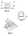
Figure 4 shows a side elevational view of the clip of the previous figures. -
Figure 5 shows a side elevational view of the clip of the previous figures, in an orthogonal position with respect to the preceding figure. -
Figure 6 shows a perspective view of another possible embodiment of the present invention. -
Figure 7 shows an upper plan view of the clip of the previous figure. -
Figure 8 shows lower plan view of the clip offigures 6 and7 . -
Figure 9 shows a side elevational view of the clip offigures 6 ,7 and 8 . -
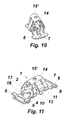
Figure 10 shows a transversal section, with respect to the longest longitudinal direction thereof, of the clip of the preceding figure. -
Figure 11 shows one of the possible embodiments of the invention, specifically, the one represented byfigures 6 to 10 , wherein it is schematically shown the assembling of the clip. - Figure 12 shows a perspective view of another embodiment of the invention, similar to the one represented in the preceding figures, but with an overall vault-shaped and/or conical configuration, provided with a head or rounded central surface, double thread, one in each base, and extreme composition parts that can be made of plastic.
- Figure 13 is a perspective representation, in a lower view, of the embodiment of the previous figure.
- Figure 14 is another perspective representation that may correspond to the two previous figures, with the peculiarity that it utilizes a threaded cylinder as a threaded element.
- The graphic merely shows the central portion, without the addition of the end wings.
- Figure 15 also shows another possible embodiment of the present invention. In point of fact, several combinations of the elements forming the clip are possible without departing from the essence of the present invention.
- Figure 16 is another of the preferred possible embodiments of the invention, wherein the upper surface is blunt and has an orifice and side wings that are smooth, devoid of reinforcing deformations, these being elements that can be utilized in different combinations depending on the operational requirements of the piece without this affecting the essence of the invention.
- The present invention comprises a roof clip of the type used for attaching accessories to the panels of vehicles and inserted slots made in said panels, wherein once the clip is assembled on the modular system of the roof, along with the accessory thereof, and secured by means of a screw, the entire modular system is installed on the roof panel, which panel is provided with a base (2) having a threaded orifice, slots (16) at said base (2) for the engagement with the positioning elements of the accessory to be installed with the clip (1), it being provided with fastening wings (11) of the clip (1) to the vehicle panel thanks to a contact surface (12) with said panel, the invention being also provided with flanges (13) for extracting said clip from said panel, wherein there has been perfomed the overlapping of a lower base (3) with said intermediate base (2) while keeping aligned the thread (5) of said intermediate base (2) and the lower orifice (18) of said lower base (3).
- The superposition of bases (2 and 3) is obtained, as seen in the figures accompanying the invention, thanks to the overlapping of said lower base (3) underneath the intermediate base (2) resulting from folding and forming the conical body of the clip with an upper surface (14), blunt and narrow, or approximately flat, depending on each actual embodiment, from which arms (10) attaching said surface to said bases (2 and 3) and descending side wings (11) extend.
- Said side wings (11) permit, thanks to a fold made towards the interior of the clip, a support and contact surface (12) of said wings (11) against the edges of the orifice or slot made in the panel. Said contact or abutment keeps the clip (1) from exiting said slot panel.
- In the preferred embodiment, shown in
figures 1 to 5 , the side wings (11) feature elbowed side surfaces (24). Said surfaces are subdivided into two portions, a first portion (27) located at the area adjacent to the vertex of the clip (1), the surface (14), which is the surface having the most inclination with respect to the vertical, and a second portion (28) that features an enlarged surface. - The purpose of the above subdivided shape is on the one hand to provide a gradient suitable for diminishing the entry and insertion force into the panel and at the same time to provide said wing (11) with a suitable resistant working area.
- In this preferred embodiment, the contact and engagement surface (12) of said wings (11) with the panel comprises elongated flanges that are folded against the surface of said panel and secured to the ends of the elbowed side surfaces (24) of the wings (11).
- The extraction flanges (73) of the clip are disposed descending downwardly from said wings (11). When, upon engagement of the clip (1) with the panel, said flanges (13) become attracted towards the center of the clip the engagement of the surfaces (12) is released and the clip is freed from the panel.
- In order to facilitate the above operation, the base of the clip (1) is provided at its side with a rebated surface (19).
- Said wings (11) and said flanges (13) can feature reinforcing deformations (22).
- Likewise, the arms (10) securing said bases (2 and 3) to the surface (14), which is narrow in the preferred embodiment shown in
figures 1 to 5 , have two portions, the first one (23) being adjacent to said surface (14) and having a higher degree of incline with respect to the vertical of the clip (1) in order to facilitate the entry thereof into the orifice of the panel. - The arms, if need be, (10) may be provided with reinforcements (25), for instance in the form of deformations of the surface thereof.
- The base (2) of the clip extends in the largest longitudinal direction in order to form transverse wings (7) that work against the panel on the face opposed to that of the surface (12) of said wings (11).
- The surface of said transverse wings (7) that is intended to be brought into contact with the panel is provided with reliefs against friction with said panel in the form of support protuberances (26). Said protuberances or other similar type of formations are intended to avoid contact areas between the clip (1) and the sharp-edged panel, thereby diminishing the noise resulting from the friction between both.
- The joining between said base (2) and said wings (7) is made in the examples of
figures 1 to 5 by means of a longitudinal tongue (29). - As seen in
figures 1 to 5 of said embodiment, contact surfaces of the clip (1) with the exterior of the panel, the protuberances (26), lie at an enlarged distance with respect to the center of the clip, both in the longitudinal direction and in the transverse direction thereof. - This construction and the fact that from a sectional point of view the wings (7) are "V"-shaped provide suitable operational elasticity reserve and good adaptation to different panel thicknesses, said "V" being centered on the axis of the clip and having the ends thereof located at the ends of the wings and the protuberances (26) raised with respect to the plane of said clip.
- In another of the preferred embodiments, the one shown in
figures 6 to 11 , the side wings (11) feature an intermediate fold and/or a progressive change in the inclination of said wing, which can also incorporate reinforcements (22) in order to prevent the premature deformation thereof when the extraction force is applied. - This clip (1) also incorporates a simple means for extraction from the panel slot, consisting in the presence of flanges (13) that extend into said side wings (11) and further extend from said engagement surface (12). Upon exertion of pressure on said flanges (13), the surface (12) and the wings (11) can be released from the edges of the panel slot, thereby freeing the clip (1).
- The lower base (3) is provided with fastening flanges (4) that are folded over the surface or intermediate base (2) into notches (17) made in the slots (16) of said base (2) of the clip. The slots (16) are intended to house the elements for fastening the accessories assembled with the clip (1).
- Said notches (17) are intended to have said flanges fitted into them, without plays, this resulting in a secure and stable fastening devoid of mutual side displacements of the surfaces or bases (3 and 2) prior to the screwing of the accessory to be fastened to the clip (1).
- In some embodiments the intermediate base (2) can feature at its side extensions of the longer longitudinal direction a step (6) located on a plane approximately identical to that of said lower base (3) and wings (7) transversally extending towards the longer longitudinal direction of the clip. These wings (7) can incorporate respective reinforcing flanges (8) that extend further in said transverse direction.
- This construction provides several outcomes worth noting. On the one hand, it is diminished the contact surface between the piece or clip (1), at the area of the wings (7) and the panel surface, and on the other hand this mutual relation has some degree of elasticity resulting from the relative rigidity of said flanges (8). A fold (9) at the end of said flanges (8) avoids any kind of aggression to them against the panel surface.
- This type of clip can incorporate a reinforcement (15) or a drill (15') on the flat surface (14), if required by the application, so that in case a reinforcement (15) is used the extraction force can be increased or, in case the drill (15') is used the insertion force can be diminished and the reliability in the manufacture of the clip itself can be improved.
- There may be different surface (14) combinations, flat or blunt, with the possibility of having said drill (15') or said cavity or reinforcement (15) available. Said flat or blunt surface (14), or like in the preferred embodiment a particularly flat surface, can be adapted to the insertion slot of the panel, which facilitates the insertion thereof.
- It is worth noting that not only the conical shape of the central portion of the clip (1) facilitates the insertion thereof, but also the very structure of the clip (1) provided with a blunt surface, or approximately flat, or particularly narrow (14), from which extend said wings (11), that are provided with a progressive entry into the panels by way of a progressive change of inclination thereof, along with the also progressive external lateral shape of the arms attaching the upper blunt surface to the bases, all of which facilitates the correct alignment and subsequent insertion into the panel slot, helps assembling and considerably reduces the required insertion force.
- Similarly, it is provided a notch (19) in said base of the clip (2) that is basically intended to permit the operation of the tool suitable for disassembling the clip, thereby facilitating access to the extraction flanges (13) of the clip.
- The incorporation of protuberances (26) for support or flexible flanges (8) on the wings (7) considerably reduces, as compared to the winged base configuration of Spanish patent
ES2107378 - Another possible embodiment of the present invention is shown in figures 12 and 13. In these cases there also exists the overlapping of a lower base (3) and an intermediate base (2) that keeps aligned, for this configuration, a double thread given the fact that each base incorporates a single thread and they are conveniently spaced from each other so that each base can adequately adapt for passage of the screw that is in operation.
- An addition feature of this embodiment is that the wings (7) and the support flanges have been replaced by support wings, in an independent body (21), that are made of plastic material and are either integrated in the clip, directly injected in the clip or assembled under pressure and fitted into the flaps (20) provided in both bases. In this manner, the very plastic piece ensures the engagement as a whole of the two bases and at the same time provides a low insertion force. It is to be noted the reduced weight of this embodiment since it incorporates two pieces made of plastic material.
- In figure 14 it is represented a variation of the previous embodiment, since it incorporates a threaded tube at the intermediate base and an orifice at the lower base. With that it is achieved, like in the preferred embodiment of
figures 1 to 5 , an increase of the tightening torque in those applications requiring it. - In the embodiment shown in figure 15, said wings (7) and flanges (8) are formed by the overlapping of the lower base (3) and said intermediate base (2). For instance, the intermediate base (2) extends transversally in the larger longitudinal direction of the clip (1) in the form of flanges (8) that protrude from the body of said lower base (3).
-
Figure 11 shows an application of the invention in which it is worth noting the reduced dimensions of the clip so that it can adapt to those situations in which the assembling space is reduced. - Finally, figure 16 shows another possible embodiment of the invention. In this case the upper surface (14) is blunt and provided with a drill (15'). Further, the side wings (11) are smooth and devoid of the reinforcements (22) present in other embodiments.
- In this case the thread is formed through the overlapping of a lower base (3) and its intermediate base (2) that keeps aligned the lower orifice of said lower base and the thread (5) of said intermediate base (2) .
- It is understood that finish or shape details in the present case are liable to variation provided that the essence of the invention is not altered.
Claims (28)
- ROOF CLIP FOR FASTENING ACCESSORIES TO THE PANELS OF VEHICLES, of the type that is inserted into a slot made in said panels, wherein the clip is assembled on the modular system of the roof along with the accessory and secured by means of a screw, said clip having a base (2) provided with a threaded orifice (5), slots (16) in said base (2), said clip further featuring side wings (11) whose folding creates a contact surface (12) with said panel, said clip being also provided with flanges (13) for extracting said clip from said panel, CHARACTERIZED in that there is performed the overlapping of a lower base (3) and said intermediate base (2), said thread (5) of said intermediate base (2) and the lower orifice (18) of said lower base (3) being kept aligned.
- ROOF CLIP, according to claim 1, CHARACTERIZED in that both bases (2 and 3) are attached to an upper surface (14) by means of arms (10) forming an overall inverted "V"-shaped configuration with the end thereof in said surface (14).
- ROOF CLIP, according to the previous claims, CHARACTERIZED in that said lower base (3) is provided with fastening flanges (4) that are folded onto the surface or intermediate base (2) through said slots (16) of said base (2) of the clip (1).
- ROOF CLIP, according to the previous claims, CHARACTERIZED by featuring a steeper inclination (23), with respect to the vertical, at the portion nearest to said surface (14) of the clip (1) in said arms (10).
- ROOF CLIP, according to the previous claims, CHARACTERIZED by featuring reinforcements (25) in said arms (10) .
- ROOF CLIP, according to the previous claims, CHARACTERIZED in that said side wings (11) are provided with respective elbowed side surfaces (24).
- ROOF CLIP, according to the previous claims, CHARACTERIZED in that said elbowed side surfaces (24) feature a first portion (27) having a steeper inclination with respect to the vertical in its area closest to said surface (14), and a second portion having an enlarged surface (28).
- ROOF CLIP, according to the previous claims, CHARACTERIZED in that said surface (12) is formed by elongated flanges that are bent against the surface of said panel and secured to the ends of the elbowed side surfaces (24) of the wings (11).
- ROOF CLIP, according to the previous claims, CHARACTERIZED in that said flanges and said wings (11) can be provided with reinforcements (22) on the surface thereof.
- ROOF CLIP, according to the previous claims, CHARACTERIZED in that said intermediate base (2) is provided with a notch (19) located at the side central areas thereof intended to facilitate access to flanges (13) in the dismantling opertation of the clip.
- ROOF CLIP, according to the previous claims, CHARACTERIZED in that said thread (5) of said intermediate base (2) is a threaded cylinder.
- ROOF CLIP, according to the previous claims, CHARACTERIZED in that it is provided with notches (17) made in said slots (16) of said base (2) of the clip (1) wherein said fastening flanges (4) of said lower base (3) are folded onto said surface or intermediate base (2).
- ROOF CLIP, according to the previous claims, CHARACTERIZED in that the lower orifice (18) of said lower base (3) is also threaded.
- ROOF CLIP, according to the previous claims, CHARACTERIZED in that the contact surfaces of the clip (1) with the external portion of the panel are located at an extended distance from the center of the clip, both longitudinally and transversally speaking.
- ROOF CLIP, according to the previous claims, CHARACTERIZED in that said clip (1) features wings (7) at the prolongations of its base in the larger longitudinal direction thereof.
- ROOF CLIP, according to the previous claims, CHARACTERIZED in that said upper surface (14) is blunt.
- ROOF CLIP, according to the previous claims, CHARACTERIZED in that said upper surface (14) is approximately pointed and narrow.
- ROOF CLIP, according to the previous claims, CHARACTERIZED in that said upper surface (14) is flat.
- ROOF CLIP, according to the previous claims, CHARACTERIZED in that said upper surface (14) is provided with a notch of material in the form of an orifice (15').
- ROOF CLIP, according to claims 1 to 18, CHARACTERIZED in that said upper surface (14) is provided with a reinforcement (15) on the surface thereof.
- ROOF CLIP, according to the previous claims, CHARACTERIZED in that said wings (7) transversally extend in said larger longitudinal direction of the clip (1) and have the ends thereof raised approximately in the form of a "V" centered on the axis of said clip (1).
- ROOF CLIP, according to the previous claims, CHARACTERIZED in that it is provided with support protuberances (26) at the ends of said wings (7).
- ROOF CLIP, according to the previous claims, CHARACTERIZED in that said intermediate base (2) and said wings (7) are joined by a longitudinal tongue (29).
- ROOF CLIP, according to claims 1 to 20, CHARACTERIZED in that said intermediate base (2) features at its side prolongations of its larger longitudinal direction a descending step (6) that joins said wings (7) by incorporating respective support flanges (8).
- ROOF CLIP, according to the previous claim, CHARACTERIZED in that said flanges (8) are provided at the ends thereof with a fold (9) intended to avoid damaging contact against the surface of the panel.
- ROOF CLIP, according to claims 1 to 20, CHARACTERIZED in that said intermediate base (2) and said lower base (3), both overlapped, also overlap each other and form said wings (7) that feature transverse extensions in the larger longitudinal direction of said clip (1) resulting from the extension of said intermediate base (2).
- ROOF CLIP, according to claim 1 to 20, CHARACTERIZED in that it has been suppressed from the body of said clip (1) said wings (7), said clip (1) featuring flaps (20) in both bases (2 and 3) where it can be inserted an independent body (21) that makes said wings (7).
- ROOF CLIP, according to the previous claim, CHARACTERIZED in that said independent body is made of plastic material or plastic composite.
Applications Claiming Priority (2)
| Application Number | Priority Date | Filing Date | Title |
|---|---|---|---|
| ES200901700A ES2356761B1 (en) | 2009-07-31 | 2009-07-31 | ROOF CLIP FOR FIXING ACCESSORIES TO VEH� CULOS PANELS. |
| PCT/ES2010/000184 WO2011012739A1 (en) | 2009-07-31 | 2010-04-27 | Roof clip for attaching accessories to the panels of vehicles |
Publications (3)
| Publication Number | Publication Date |
|---|---|
| EP2460693A1 true EP2460693A1 (en) | 2012-06-06 |
| EP2460693A4 EP2460693A4 (en) | 2012-12-19 |
| EP2460693B1 EP2460693B1 (en) | 2016-04-27 |
Family
ID=43528809
Family Applications (1)
| Application Number | Title | Priority Date | Filing Date |
|---|---|---|---|
| EP10803930.6A Active EP2460693B1 (en) | 2009-07-31 | 2010-04-27 | Roof clip for attaching accessories to the panels of vehicles |
Country Status (5)
| Country | Link |
|---|---|
| US (1) | US9156414B2 (en) |
| EP (1) | EP2460693B1 (en) |
| CN (1) | CN102470803B (en) |
| ES (1) | ES2356761B1 (en) |
| WO (1) | WO2011012739A1 (en) |
Families Citing this family (17)
| Publication number | Priority date | Publication date | Assignee | Title |
|---|---|---|---|---|
| USD665725S1 (en) * | 2011-08-01 | 2012-08-21 | Thule Sweden Ab | Folding rooftop carrier |
| WO2013019815A1 (en) | 2011-08-01 | 2013-02-07 | Thule Sweden Ab | Kayak transport device for a vehicle |
| US9500210B2 (en) * | 2012-03-02 | 2016-11-22 | Illinois Tool Works Inc. | Airbag anchoring clip assembly |
| US9903407B2 (en) | 2013-10-29 | 2018-02-27 | Piolax, Inc. | Fastener |
| CN103591110A (en) * | 2013-11-15 | 2014-02-19 | 上汽通用五菱汽车股份有限公司 | Nut seat |
| KR101582898B1 (en) * | 2014-10-24 | 2016-01-08 | (주)대한솔루션 | Fixture for vehicle |
| US9440596B2 (en) * | 2014-11-20 | 2016-09-13 | Ford Global Technologies, Llc | Retention clip for interior vehicle components |
| US10047783B2 (en) | 2016-06-27 | 2018-08-14 | The Boeing Company | Flex reduction clip nut |
| US10837481B2 (en) | 2018-02-22 | 2020-11-17 | A. Raymond Et Cie | Flush mount retainer assembly |
| US11773895B2 (en) * | 2019-05-01 | 2023-10-03 | Erico International Corporation | Spring nut with release |
| CN112081802B (en) * | 2019-06-14 | 2024-09-03 | 伊利诺斯工具制品有限公司 | Fastening clip |
| US20210062855A1 (en) * | 2019-08-27 | 2021-03-04 | Illinois Tool Works Inc. | Ergonomic Box Nut Retainer |
| USD1003807S1 (en) * | 2019-09-20 | 2023-11-07 | Canoo Technologies Inc. | In-vehicle accessory attachment clip |
| EP3936681B1 (en) * | 2020-07-10 | 2025-08-20 | Schmitt, Götz S. | Mounting system |
| US12049916B2 (en) * | 2021-02-05 | 2024-07-30 | Erico International Corporation | Spring nut |
| KR20240079406A (en) * | 2022-11-29 | 2024-06-05 | (주)대한솔루션 | Module clip for vehicles |
| US20240198929A1 (en) * | 2022-12-14 | 2024-06-20 | Termax Company | Fastener Clip Assembly with Multiple Threads for Receiving a Screw |
Family Cites Families (49)
| Publication number | Priority date | Publication date | Assignee | Title |
|---|---|---|---|---|
| US2815789A (en) * | 1954-06-25 | 1957-12-10 | Floyd B Odlum | Nut retainer which is distortable to permit assembly of nut therewith |
| US2908311A (en) * | 1957-07-19 | 1959-10-13 | Prestole Corp | Panel fastener having a caged nut and cage with detent holding means |
| US3205546A (en) * | 1963-08-28 | 1965-09-14 | Illinois Tool Works | Adjustable removable molding clip |
| US3362278A (en) * | 1966-05-06 | 1968-01-09 | Bishop & Babcock Corp | Nut impressions |
| US3486158A (en) * | 1967-09-29 | 1969-12-23 | Illinois Tool Works | Grounding clip |
| US4606688A (en) * | 1982-12-15 | 1986-08-19 | Eaton Corporation | Removable fastening assembly |
| US4925351A (en) * | 1989-03-21 | 1990-05-15 | Trw, Inc. | Push-in fastener clip |
| US5249900A (en) * | 1992-09-18 | 1993-10-05 | California Industrial Products, Inc. | Threaded fastener for mounting within an opening in a panel |
| US5857735A (en) * | 1994-06-20 | 1999-01-12 | Irausa Ingenieria, S.A. | Self-supporting roof with built-in fittings directly mountable upon vehicle roofs |
| ES2107378B1 (en) * | 1994-06-20 | 1998-06-01 | Irausa Ing Sa | IMPROVEMENTS INTRODUCED IN INVENTION PATENT No. 9401338, BY "SELF-SUPPORTING CEILING WITH INTEGRATED ACCESSORIES FOR DIRECT MOUNTING ON VEHICLE CEILINGS. |
| US5636891A (en) * | 1995-06-07 | 1997-06-10 | Prince Corporation | Adjustable fastener |
| BR9804863A (en) * | 1997-04-22 | 2005-08-23 | Irausa Ing Sa | System for attaching accessories to panels and / or self-supporting elements for the internal lining of vehicles. |
| AU1277099A (en) * | 1997-10-24 | 1999-05-17 | Findlay Industries | Vehicular accessory fastener |
| EP1186787B1 (en) * | 2000-03-24 | 2004-11-17 | Grupo Antolin-Ingenieria, S.A. | Metal-plastic staple for fixing vehicle roofs and accessories to the body of a vehicle |
| US7168138B2 (en) * | 2000-03-27 | 2007-01-30 | Newfrey Llc | Resilient clip fastener |
| US6629809B2 (en) * | 2000-11-08 | 2003-10-07 | Termax Corporation | Sheet metal fastener with multiple engagement |
| US6908274B1 (en) * | 2000-11-20 | 2005-06-21 | Termax Corporation | Combination fastener |
| JP3699048B2 (en) * | 2001-02-01 | 2005-09-28 | ハン イル エ ワ カンパニーリミテッド | Goods mounting clip |
| US8627552B2 (en) * | 2001-06-25 | 2014-01-14 | Termax Corporation | Multicontact adaptive fastener clip |
| US8950042B2 (en) * | 2001-06-25 | 2015-02-10 | Termax Corporation | Continuously adaptive fastener clip |
| CN1317147C (en) * | 2001-10-15 | 2007-05-23 | 安托林工程集团股份有限公司 | Accessory fixing system for vehicle interiors |
| US20040049894A1 (en) * | 2002-06-24 | 2004-03-18 | Nicholas Jackson | Sheet metal fastening clip |
| US7226260B2 (en) * | 2002-06-24 | 2007-06-05 | A. Raymond, Inc. | Sheet metal fastening clip |
| US7186051B2 (en) * | 2003-05-09 | 2007-03-06 | Newfrey Llc | Metal/plastic insert molded sill plate fastener |
| US6976292B2 (en) * | 2003-08-28 | 2005-12-20 | Newfrey Llc | Resilient clip fastener |
| US8083450B1 (en) * | 2003-11-12 | 2011-12-27 | Termax Corporation | Removable anchor and fastener |
| US7086125B2 (en) * | 2004-04-23 | 2006-08-08 | Newfrey Llc | Multiple stage assembly assist fastener |
| DE102004052332B4 (en) * | 2004-10-27 | 2006-09-14 | Springfix-Befestigungstechnik Gmbh | Clip-mother |
| DE102004063686B4 (en) * | 2004-12-31 | 2007-04-12 | A. Raymond & Cie | Clamp for connecting an attachment body with a base body |
| US7356886B2 (en) * | 2005-04-14 | 2008-04-15 | Piolax, Inc. | Clamp |
| US7152281B2 (en) * | 2005-04-28 | 2006-12-26 | Illinois Tool Works Inc | Fastener and fastened assembly |
| US20070046054A1 (en) * | 2005-08-31 | 2007-03-01 | Hinman David T | Interior trim accessory attachment apparatus |
| US7293824B2 (en) * | 2005-09-13 | 2007-11-13 | International Automotive Components Group North America, Inc. | Visor attachment member |
| DE102006001741A1 (en) * | 2006-01-13 | 2007-08-02 | A. Raymond Et Cie | Captive threaded nut for latching into hole in plate is formed with self retaining spring arms |
| DE202006001894U1 (en) * | 2006-02-03 | 2007-06-06 | Carcoustics Tech Center Gmbh | Fastener for vehicle parts |
| US20070224018A1 (en) * | 2006-03-03 | 2007-09-27 | Deperro Charles A | Fastening device |
| NL1031555C2 (en) * | 2006-04-10 | 2007-10-11 | Walraven Holding Bv J Van | Pipe bracket with spring nut. |
| JP4738323B2 (en) * | 2006-12-06 | 2011-08-03 | 株式会社パイオラックス | Fastener |
| DE202007006097U1 (en) * | 2007-04-27 | 2008-09-04 | Lisi Automotive Rapid | Device for fastening components to one another with the aid of a clamp which can be pushed onto a component |
| KR100808846B1 (en) * | 2007-05-23 | 2008-03-03 | 엔브이에이치코리아(주) | Car interior parts fixing clip |
| US8016530B2 (en) * | 2008-01-10 | 2011-09-13 | Illinois Tool Works Inc. | Panel fastener |
| US7878745B2 (en) * | 2008-06-16 | 2011-02-01 | Illinois Tool Works Inc. | U-nut fastener and collated strip thereof |
| DE102008039180A1 (en) * | 2008-08-19 | 2010-02-25 | A.Raymond Et.Cie | Reinforcing part and airbag arrangement |
| JP2010053993A (en) * | 2008-08-29 | 2010-03-11 | Daiwa Kasei Kogyo Kk | Two-member assembling structure |
| BRPI1007013A2 (en) * | 2009-02-12 | 2016-03-29 | Illinois Tool Works | Removable, reusable U-shaped hybrid nut extends service life. |
| US9168878B2 (en) * | 2011-01-14 | 2015-10-27 | Illinois Tool Works Inc. | Roof ditch molding retainer assembly |
| US8807895B2 (en) * | 2011-07-13 | 2014-08-19 | Toyota Motor Engineering & Manufacturing North America, Inc. | Fastener housing for securing a bumper fascia to a fender panel of an automotive vehicle |
| EP2551531B1 (en) * | 2011-07-25 | 2017-03-22 | Faurecia Interieur Industrie | Attachment device for fixing on a plate having a hole and assembly comprising such an attachment device |
| US8579570B2 (en) * | 2011-08-11 | 2013-11-12 | GM Global Technology Operations LLC | Fastener attaching a component to a panel |
-
2009
- 2009-07-31 ES ES200901700A patent/ES2356761B1/en active Active
-
2010
- 2010-04-27 US US13/387,920 patent/US9156414B2/en active Active
- 2010-04-27 EP EP10803930.6A patent/EP2460693B1/en active Active
- 2010-04-27 CN CN201080033857.3A patent/CN102470803B/en active Active
- 2010-04-27 WO PCT/ES2010/000184 patent/WO2011012739A1/en not_active Ceased
Also Published As
| Publication number | Publication date |
|---|---|
| WO2011012739A1 (en) | 2011-02-03 |
| CN102470803B (en) | 2014-10-01 |
| ES2356761A1 (en) | 2011-04-13 |
| EP2460693A4 (en) | 2012-12-19 |
| EP2460693B1 (en) | 2016-04-27 |
| US20120125960A1 (en) | 2012-05-24 |
| CN102470803A (en) | 2012-05-23 |
| US9156414B2 (en) | 2015-10-13 |
| ES2356761B1 (en) | 2012-02-29 |
Similar Documents
| Publication | Publication Date | Title |
|---|---|---|
| US9156414B2 (en) | Roof clip for fastening accessories to the panels of vehicles | |
| US7841817B2 (en) | Pin and bush fastener with high fastening strength, and airbag attached to vehicle body by such a fastener | |
| EP1832760B1 (en) | Trim Retainer | |
| US20100025547A1 (en) | Clip for fastening an article to a panel having a self-expanding clip head | |
| US8414068B1 (en) | Vehicle body structure | |
| EP1905652B1 (en) | Garnish attachment structure of vehicle body | |
| US8491243B2 (en) | Variable grip blind rivet | |
| US5074726A (en) | Blind fastener | |
| CN104246243B (en) | Fastener retention device | |
| KR20120065338A (en) | Device for connecting two components | |
| US20130026788A1 (en) | Nut and vehicle part comprising such a nut | |
| US8292560B2 (en) | Anchor device with double-sectioned head and method of using the same | |
| EP2302231A1 (en) | Plastik blind rivet | |
| US20090097939A1 (en) | Fastening element | |
| US8622680B1 (en) | Grommet | |
| US20040208721A1 (en) | Fastener adapted for use with a structural member | |
| US6921237B2 (en) | Fastener having a tab in the contact region | |
| EP4081717B1 (en) | Hinged retainer assembly | |
| US10137937B1 (en) | Roof assembly for a vehicle | |
| EP2881600A1 (en) | Fixture | |
| JP5185229B2 (en) | Structure with stud bolt | |
| JP2008223885A (en) | clip | |
| US20260039238A1 (en) | System for securing a torque tube to a mounting rail | |
| US20240328451A1 (en) | Système de fixation à un goujon fileté | |
| CN220955127U (en) | Installation fixed establishment and hidden automobile-used outer handle of handle |
Legal Events
| Date | Code | Title | Description |
|---|---|---|---|
| PUAI | Public reference made under article 153(3) epc to a published international application that has entered the european phase |
Free format text: ORIGINAL CODE: 0009012 |
|
| 17P | Request for examination filed |
Effective date: 20120228 |
|
| AK | Designated contracting states |
Kind code of ref document: A1 Designated state(s): AT BE BG CH CY CZ DE DK EE ES FI FR GB GR HR HU IE IS IT LI LT LU LV MC MK MT NL NO PL PT RO SE SI SK SM TR |
|
| DAX | Request for extension of the european patent (deleted) | ||
| A4 | Supplementary search report drawn up and despatched |
Effective date: 20121116 |
|
| RIC1 | Information provided on ipc code assigned before grant |
Ipc: F16B 37/02 20060101ALI20121112BHEP Ipc: B60R 13/02 20060101AFI20121112BHEP Ipc: F16B 37/04 20060101ALI20121112BHEP |
|
| RAP1 | Party data changed (applicant data changed or rights of an application transferred) |
Owner name: ILLINOIS TOOL WORKS INC. |
|
| 17Q | First examination report despatched |
Effective date: 20140528 |
|
| GRAP | Despatch of communication of intention to grant a patent |
Free format text: ORIGINAL CODE: EPIDOSNIGR1 |
|
| INTG | Intention to grant announced |
Effective date: 20151127 |
|
| GRAS | Grant fee paid |
Free format text: ORIGINAL CODE: EPIDOSNIGR3 |
|
| GRAA | (expected) grant |
Free format text: ORIGINAL CODE: 0009210 |
|
| AK | Designated contracting states |
Kind code of ref document: B1 Designated state(s): AT BE BG CH CY CZ DE DK EE ES FI FR GB GR HR HU IE IS IT LI LT LU LV MC MK MT NL NO PL PT RO SE SI SK SM TR |
|
| REG | Reference to a national code |
Ref country code: GB Ref legal event code: FG4D |
|
| REG | Reference to a national code |
Ref country code: CH Ref legal event code: EP |
|
| REG | Reference to a national code |
Ref country code: AT Ref legal event code: REF Ref document number: 794372 Country of ref document: AT Kind code of ref document: T Effective date: 20160515 |
|
| REG | Reference to a national code |
Ref country code: IE Ref legal event code: FG4D |
|
| REG | Reference to a national code |
Ref country code: DE Ref legal event code: R096 Ref document number: 602010032895 Country of ref document: DE |
|
| REG | Reference to a national code |
Ref country code: LT Ref legal event code: MG4D |
|
| PG25 | Lapsed in a contracting state [announced via postgrant information from national office to epo] |
Ref country code: BE Free format text: LAPSE BECAUSE OF NON-PAYMENT OF DUE FEES Effective date: 20160430 |
|
| REG | Reference to a national code |
Ref country code: NL Ref legal event code: MP Effective date: 20160427 |
|
| REG | Reference to a national code |
Ref country code: AT Ref legal event code: MK05 Ref document number: 794372 Country of ref document: AT Kind code of ref document: T Effective date: 20160427 |
|
| PG25 | Lapsed in a contracting state [announced via postgrant information from national office to epo] |
Ref country code: NL Free format text: LAPSE BECAUSE OF FAILURE TO SUBMIT A TRANSLATION OF THE DESCRIPTION OR TO PAY THE FEE WITHIN THE PRESCRIBED TIME-LIMIT Effective date: 20160427 |
|
| PG25 | Lapsed in a contracting state [announced via postgrant information from national office to epo] |
Ref country code: NO Free format text: LAPSE BECAUSE OF FAILURE TO SUBMIT A TRANSLATION OF THE DESCRIPTION OR TO PAY THE FEE WITHIN THE PRESCRIBED TIME-LIMIT Effective date: 20160727 Ref country code: PL Free format text: LAPSE BECAUSE OF FAILURE TO SUBMIT A TRANSLATION OF THE DESCRIPTION OR TO PAY THE FEE WITHIN THE PRESCRIBED TIME-LIMIT Effective date: 20160427 Ref country code: FI Free format text: LAPSE BECAUSE OF FAILURE TO SUBMIT A TRANSLATION OF THE DESCRIPTION OR TO PAY THE FEE WITHIN THE PRESCRIBED TIME-LIMIT Effective date: 20160427 Ref country code: LT Free format text: LAPSE BECAUSE OF FAILURE TO SUBMIT A TRANSLATION OF THE DESCRIPTION OR TO PAY THE FEE WITHIN THE PRESCRIBED TIME-LIMIT Effective date: 20160427 |
|
| PG25 | Lapsed in a contracting state [announced via postgrant information from national office to epo] |
Ref country code: ES Free format text: LAPSE BECAUSE OF FAILURE TO SUBMIT A TRANSLATION OF THE DESCRIPTION OR TO PAY THE FEE WITHIN THE PRESCRIBED TIME-LIMIT Effective date: 20160427 Ref country code: HR Free format text: LAPSE BECAUSE OF FAILURE TO SUBMIT A TRANSLATION OF THE DESCRIPTION OR TO PAY THE FEE WITHIN THE PRESCRIBED TIME-LIMIT Effective date: 20160427 Ref country code: SE Free format text: LAPSE BECAUSE OF FAILURE TO SUBMIT A TRANSLATION OF THE DESCRIPTION OR TO PAY THE FEE WITHIN THE PRESCRIBED TIME-LIMIT Effective date: 20160427 Ref country code: LV Free format text: LAPSE BECAUSE OF FAILURE TO SUBMIT A TRANSLATION OF THE DESCRIPTION OR TO PAY THE FEE WITHIN THE PRESCRIBED TIME-LIMIT Effective date: 20160427 Ref country code: GR Free format text: LAPSE BECAUSE OF FAILURE TO SUBMIT A TRANSLATION OF THE DESCRIPTION OR TO PAY THE FEE WITHIN THE PRESCRIBED TIME-LIMIT Effective date: 20160728 Ref country code: PT Free format text: LAPSE BECAUSE OF FAILURE TO SUBMIT A TRANSLATION OF THE DESCRIPTION OR TO PAY THE FEE WITHIN THE PRESCRIBED TIME-LIMIT Effective date: 20160829 Ref country code: AT Free format text: LAPSE BECAUSE OF FAILURE TO SUBMIT A TRANSLATION OF THE DESCRIPTION OR TO PAY THE FEE WITHIN THE PRESCRIBED TIME-LIMIT Effective date: 20160427 |
|
| REG | Reference to a national code |
Ref country code: CH Ref legal event code: PL |
|
| PG25 | Lapsed in a contracting state [announced via postgrant information from national office to epo] |
Ref country code: BE Free format text: LAPSE BECAUSE OF FAILURE TO SUBMIT A TRANSLATION OF THE DESCRIPTION OR TO PAY THE FEE WITHIN THE PRESCRIBED TIME-LIMIT Effective date: 20160427 Ref country code: IT Free format text: LAPSE BECAUSE OF FAILURE TO SUBMIT A TRANSLATION OF THE DESCRIPTION OR TO PAY THE FEE WITHIN THE PRESCRIBED TIME-LIMIT Effective date: 20160427 |
|
| REG | Reference to a national code |
Ref country code: IE Ref legal event code: MM4A |
|
| REG | Reference to a national code |
Ref country code: DE Ref legal event code: R097 Ref document number: 602010032895 Country of ref document: DE |
|
| PG25 | Lapsed in a contracting state [announced via postgrant information from national office to epo] |
Ref country code: CH Free format text: LAPSE BECAUSE OF NON-PAYMENT OF DUE FEES Effective date: 20160430 Ref country code: EE Free format text: LAPSE BECAUSE OF FAILURE TO SUBMIT A TRANSLATION OF THE DESCRIPTION OR TO PAY THE FEE WITHIN THE PRESCRIBED TIME-LIMIT Effective date: 20160427 Ref country code: DK Free format text: LAPSE BECAUSE OF FAILURE TO SUBMIT A TRANSLATION OF THE DESCRIPTION OR TO PAY THE FEE WITHIN THE PRESCRIBED TIME-LIMIT Effective date: 20160427 Ref country code: CZ Free format text: LAPSE BECAUSE OF FAILURE TO SUBMIT A TRANSLATION OF THE DESCRIPTION OR TO PAY THE FEE WITHIN THE PRESCRIBED TIME-LIMIT Effective date: 20160427 Ref country code: SK Free format text: LAPSE BECAUSE OF FAILURE TO SUBMIT A TRANSLATION OF THE DESCRIPTION OR TO PAY THE FEE WITHIN THE PRESCRIBED TIME-LIMIT Effective date: 20160427 Ref country code: LI Free format text: LAPSE BECAUSE OF NON-PAYMENT OF DUE FEES Effective date: 20160430 Ref country code: RO Free format text: LAPSE BECAUSE OF FAILURE TO SUBMIT A TRANSLATION OF THE DESCRIPTION OR TO PAY THE FEE WITHIN THE PRESCRIBED TIME-LIMIT Effective date: 20160427 |
|
| PG25 | Lapsed in a contracting state [announced via postgrant information from national office to epo] |
Ref country code: SM Free format text: LAPSE BECAUSE OF FAILURE TO SUBMIT A TRANSLATION OF THE DESCRIPTION OR TO PAY THE FEE WITHIN THE PRESCRIBED TIME-LIMIT Effective date: 20160427 |
|
| PLBE | No opposition filed within time limit |
Free format text: ORIGINAL CODE: 0009261 |
|
| STAA | Information on the status of an ep patent application or granted ep patent |
Free format text: STATUS: NO OPPOSITION FILED WITHIN TIME LIMIT |
|
| GBPC | Gb: european patent ceased through non-payment of renewal fee |
Effective date: 20160727 |
|
| REG | Reference to a national code |
Ref country code: FR Ref legal event code: ST Effective date: 20170228 |
|
| 26N | No opposition filed |
Effective date: 20170130 |
|
| PG25 | Lapsed in a contracting state [announced via postgrant information from national office to epo] |
Ref country code: FR Free format text: LAPSE BECAUSE OF NON-PAYMENT OF DUE FEES Effective date: 20160627 |
|
| PG25 | Lapsed in a contracting state [announced via postgrant information from national office to epo] |
Ref country code: GB Free format text: LAPSE BECAUSE OF NON-PAYMENT OF DUE FEES Effective date: 20160727 Ref country code: IE Free format text: LAPSE BECAUSE OF NON-PAYMENT OF DUE FEES Effective date: 20160427 Ref country code: SI Free format text: LAPSE BECAUSE OF FAILURE TO SUBMIT A TRANSLATION OF THE DESCRIPTION OR TO PAY THE FEE WITHIN THE PRESCRIBED TIME-LIMIT Effective date: 20160427 |
|
| PG25 | Lapsed in a contracting state [announced via postgrant information from national office to epo] |
Ref country code: MC Free format text: LAPSE BECAUSE OF FAILURE TO SUBMIT A TRANSLATION OF THE DESCRIPTION OR TO PAY THE FEE WITHIN THE PRESCRIBED TIME-LIMIT Effective date: 20160427 |
|
| PG25 | Lapsed in a contracting state [announced via postgrant information from national office to epo] |
Ref country code: HU Free format text: LAPSE BECAUSE OF FAILURE TO SUBMIT A TRANSLATION OF THE DESCRIPTION OR TO PAY THE FEE WITHIN THE PRESCRIBED TIME-LIMIT; INVALID AB INITIO Effective date: 20100427 Ref country code: CY Free format text: LAPSE BECAUSE OF FAILURE TO SUBMIT A TRANSLATION OF THE DESCRIPTION OR TO PAY THE FEE WITHIN THE PRESCRIBED TIME-LIMIT Effective date: 20160427 |
|
| PG25 | Lapsed in a contracting state [announced via postgrant information from national office to epo] |
Ref country code: MT Free format text: LAPSE BECAUSE OF NON-PAYMENT OF DUE FEES Effective date: 20160430 Ref country code: MK Free format text: LAPSE BECAUSE OF FAILURE TO SUBMIT A TRANSLATION OF THE DESCRIPTION OR TO PAY THE FEE WITHIN THE PRESCRIBED TIME-LIMIT Effective date: 20160427 Ref country code: LU Free format text: LAPSE BECAUSE OF NON-PAYMENT OF DUE FEES Effective date: 20160427 Ref country code: IS Free format text: LAPSE BECAUSE OF FAILURE TO SUBMIT A TRANSLATION OF THE DESCRIPTION OR TO PAY THE FEE WITHIN THE PRESCRIBED TIME-LIMIT Effective date: 20160427 Ref country code: TR Free format text: LAPSE BECAUSE OF FAILURE TO SUBMIT A TRANSLATION OF THE DESCRIPTION OR TO PAY THE FEE WITHIN THE PRESCRIBED TIME-LIMIT Effective date: 20160427 |
|
| PG25 | Lapsed in a contracting state [announced via postgrant information from national office to epo] |
Ref country code: BG Free format text: LAPSE BECAUSE OF FAILURE TO SUBMIT A TRANSLATION OF THE DESCRIPTION OR TO PAY THE FEE WITHIN THE PRESCRIBED TIME-LIMIT Effective date: 20160427 |
|
| P01 | Opt-out of the competence of the unified patent court (upc) registered |
Effective date: 20230606 |
|
| PGFP | Annual fee paid to national office [announced via postgrant information from national office to epo] |
Ref country code: DE Payment date: 20250429 Year of fee payment: 16 |