EP2460675A1 - Integrated Front and Rear HVAC System - Google Patents
Integrated Front and Rear HVAC System Download PDFInfo
- Publication number
- EP2460675A1 EP2460675A1 EP12157721A EP12157721A EP2460675A1 EP 2460675 A1 EP2460675 A1 EP 2460675A1 EP 12157721 A EP12157721 A EP 12157721A EP 12157721 A EP12157721 A EP 12157721A EP 2460675 A1 EP2460675 A1 EP 2460675A1
- Authority
- EP
- European Patent Office
- Prior art keywords
- airflow
- door
- airflow path
- evaporator
- path
- Prior art date
- Legal status (The legal status is an assumption and is not a legal conclusion. Google has not performed a legal analysis and makes no representation as to the accuracy of the status listed.)
- Granted
Links
- 238000010438 heat treatment Methods 0.000 claims abstract description 39
- 238000009833 condensation Methods 0.000 claims description 6
- 230000005494 condensation Effects 0.000 claims description 6
- XLYOFNOQVPJJNP-UHFFFAOYSA-N water Substances O XLYOFNOQVPJJNP-UHFFFAOYSA-N 0.000 claims description 6
- 230000001105 regulatory effect Effects 0.000 claims description 4
- 238000000034 method Methods 0.000 claims 2
- 238000011144 upstream manufacturing Methods 0.000 claims 1
- 230000009977 dual effect Effects 0.000 description 9
- 238000001816 cooling Methods 0.000 description 3
- 230000002265 prevention Effects 0.000 description 2
- 239000003507 refrigerant Substances 0.000 description 2
- 238000009423 ventilation Methods 0.000 description 2
- 238000004378 air conditioning Methods 0.000 description 1
- 230000001010 compromised effect Effects 0.000 description 1
- 239000012530 fluid Substances 0.000 description 1
- 238000004519 manufacturing process Methods 0.000 description 1
- 239000000463 material Substances 0.000 description 1
Images


Classifications
-
- B—PERFORMING OPERATIONS; TRANSPORTING
- B60—VEHICLES IN GENERAL
- B60H—ARRANGEMENTS OF HEATING, COOLING, VENTILATING OR OTHER AIR-TREATING DEVICES SPECIALLY ADAPTED FOR PASSENGER OR GOODS SPACES OF VEHICLES
- B60H1/00—Heating, cooling or ventilating [HVAC] devices
- B60H1/00007—Combined heating, ventilating, or cooling devices
- B60H1/00021—Air flow details of HVAC devices
- B60H1/00064—Air flow details of HVAC devices for sending air streams of different temperatures into the passenger compartment
-
- B—PERFORMING OPERATIONS; TRANSPORTING
- B60—VEHICLES IN GENERAL
- B60H—ARRANGEMENTS OF HEATING, COOLING, VENTILATING OR OTHER AIR-TREATING DEVICES SPECIALLY ADAPTED FOR PASSENGER OR GOODS SPACES OF VEHICLES
- B60H1/00—Heating, cooling or ventilating [HVAC] devices
- B60H1/00007—Combined heating, ventilating, or cooling devices
- B60H1/00021—Air flow details of HVAC devices
- B60H2001/00078—Assembling, manufacturing or layout details
- B60H2001/00099—Assembling, manufacturing or layout details comprising additional ventilating means
-
- B—PERFORMING OPERATIONS; TRANSPORTING
- B60—VEHICLES IN GENERAL
- B60H—ARRANGEMENTS OF HEATING, COOLING, VENTILATING OR OTHER AIR-TREATING DEVICES SPECIALLY ADAPTED FOR PASSENGER OR GOODS SPACES OF VEHICLES
- B60H1/00—Heating, cooling or ventilating [HVAC] devices
- B60H1/00007—Combined heating, ventilating, or cooling devices
- B60H1/00021—Air flow details of HVAC devices
- B60H2001/00114—Heating or cooling details
- B60H2001/00135—Deviding walls for separate air flows
-
- B—PERFORMING OPERATIONS; TRANSPORTING
- B60—VEHICLES IN GENERAL
- B60H—ARRANGEMENTS OF HEATING, COOLING, VENTILATING OR OTHER AIR-TREATING DEVICES SPECIALLY ADAPTED FOR PASSENGER OR GOODS SPACES OF VEHICLES
- B60H1/00—Heating, cooling or ventilating [HVAC] devices
- B60H1/00007—Combined heating, ventilating, or cooling devices
- B60H1/00021—Air flow details of HVAC devices
- B60H2001/00185—Distribution of conditionned air
- B60H2001/002—Distribution of conditionned air to front and rear part of passenger compartment
Definitions
- the present invention relates to an HVAC system for a vehicle and more specifically to an HVAC system with an integrated evaporator and heating core.
- FIG. 1 shows a conventional dual HVAC system 100, which requires two independent HVAC ( H eating V entilating and A ir C onditioning) units, a front HVAC unit 102 to cool the front of the vehicle and a rear HVAC unit 104 to cool the rear of the vehicle.
- the front HVAC unit 102 and the rear HVAC unit 104 are each housed in separate housings whereby the front HVAC unit 102 is disposed toward the front of the vehicle and the rear HVAC unit 104 is disposed toward the rear of the vehicle.
- the front HVAC unit 102 includes a front blower (not shown), an evaporator 106F, a heating core 108F, and an air mix door 110.
- the air mix door 110 is movable between a first position whereby all the air is directed through the heating core 108F and a second position where all the air is directed through the evaporator 106F. Airflow through the evaporator 106F, the heating core 108F or a combination thereof is directed to one or more of a defroster outlet 112, a vent outlet 114, or a heater outlet 116.
- the front HVAC unit 102 further includes a defroster door 118 and a vent/heater door 120.
- the defroster door 118 is movable between a first and second position to regulate the amount of airflow that exits the defroster outlet 112.
- the defroster door 118 is in the first position the defroster outlet 112 is closed and airflow is directed to the vent outlet 114, the heater outlet 116 or a combination thereof.
- the defroster door is in the second position the defroster outlet 112 is open and the airflow exits through the defroster outlet 112.
- the vent/heater door 120 is also movable between a first and second position to regulate airflow through the vent outlet 114 and the heater outlet 116 in a similar manner as the defroster door 118.
- the rear HVAC unit 104 also includes an evaporator 106R and a heating core 108R.
- the rear HVAC unit 104 further includes a rear blower 122, an air mix door 124, and an airflow direction door 126.
- the air mix door 124 operates in a similar manner to the air mix door 110 in the front HVAC unit 102.
- the airflow direction door 126 regulates airflow between one or more upper vents 128 and one or more floor vents 130.
- a major disadvantage to the conventional dual HVAC system 100 is the requirement of two housings, two evaporators 106F, 106R, and two heating cores 108F, 108R, which increases assembly and manufacturing costs.
- Another disadvantage to the conventional dual HVAC system 100 is that because the rear HVAC unit 104 is located toward the rear of the vehicle, the rear HVAC unit 104 requires a longer refrigerant line 132 and heating core line 134, which in turn leads to increased material and assembly costs. Further, more connecting joints are required to run the refrigerant line 132 and the heating core line 134 from the engine compartment to the rear HVAC unit 104, thereby increasing the probability of fluid leaking at any one joint in each line.
- the rear HVAC unit 104 occupies space in a center console 136 that can otherwise be utilized as storage space. Specifically, the rear HVAC unit 104 is located in the center console 136 below an arm rest 138 and a storage compartment 140. As clearly show in FIG. 1 , the rear HVAC unit 104 limits the amount of storage space in the center console 136.
- the present invention overcomes the above mentioned disadvantages by providing an HVAC system for a vehicle that includes a housing, a front HVAC unit housed in the housing and having a front blower, a first airflow path, and a front air mix door, a rear HVAC unit housed in the housing and having a rear blower, a second airflow path, and a rear air mix door.
- the HVAC system further includes an evaporator having a first portion disposed in the first airflow path and a second portion disposed in the second airflow path, and a heating core having a first portion disposed in the first airflow path and a second portion disposed in the second airflow path.
- An airflow directional door disposed between the first airflow path and the second airflow path to regulate airflow from the rear blower to the first airflow path.
- the present invention provides a bypass door movable between a first position and a second position, wherein when the bypass door is in the second position a portion of airflow from the first portion of the evaporator bypasses the first airflow path and is directed directly to a front outlet such that a temperature of the airflow can be regulated independently of a position of the front air mix door.
- the present invention provides a defroster duct and a defroster outlet divider disposed in a middle of the defroster outlet thereby forming a first defroster outlet and a second defroster outlet
- the front HVAC unit further includes a defroster outlet door having air deflection bracket extending from a top of the defroster outlet door, and wherein the defroster outlet door is movable between a first position, a second position, and a third position to regulate airflow through the first defroster outlet and the second defroster outlet.
- the invention may take physical form in certain parts and arrangement of parts, a preferred embodiment of which will be described in detail in this specification and illustrated in the accompanying drawings that form a part of the specification.
- FIG. 1 is a schematic view of a conventional dual HVAC system.
- FIG. 2A shows a schematic side view of an HVAC system according to one exemplary embodiment of the present invention.
- FIG. 2B shows a schematic side view of the HVAC system of FIG. 2A as viewed from the passenger seat.
- FIGS. 3-5 show schematic views of the HVAC system of FIGS. 2A and 2B illustrating multiple airflow patterns.
- FIGS. 6 and 7 show schematic views of an HVAC system illustrating multiple airflow patterns according to another exemplary embodiment of the present invention.
- FIGS. 8-12 show schematic views of an HVAC system illustrating multiple airflow patterns according to yet another exemplary embodiment of the present invention.
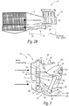
- FIG. 13 shows a schematic side view of the HVAC system of FIGS. 8-12 as viewed from the passenger seat.
- FIGS. 2-12 show several exemplary embodiments of a dual-integrated HVAC system 10 (hereinafter "HVAC system”) for an automotive vehicle in accordance with the present invention.
- HVAC system is a dual HVAC system in that the HVAC system supplies heating and cooling air to both the front and rear of the vehicle. Further, the HVAC system is an integrated HVAC system for two reasons. First, the HVAC system includes a front HVAC unit and a rear HVAC unit both housed in the same housing. Second, the HVAC system requires only a single evaporator and a single heating core for both the front and rear HVAC units. It should be noted that the evaporator and heating core of the present invention are larger than the standard evaporator and heating core for the conventional HVAC system described above. Thus, the heating/cooling efficiency and capacity of the dual-integrated HVAC system is not compromised.
- the HVAC system has several features in addition to the single evaporator and heating core mentioned above.
- One such feature is that the HVAC system has the ability to independently control airflow temperature exiting through outlets toward the front of the vehicle irrespective of airflow temperature to exiting any other ventilation outlets in the system.
- Another feature of the HVAC system is a dual airflow defroster feature to control airflow through one or more defroster outlets.
- the HVAC system includes a directional door that when in a closed position directs all the air from the rear HVAC unit to the front of the vehicle.
- a frost prevention feature to prevent frost build-up on the evaporator when the rear HVAC unit is in an "OFF" position.
- the HVAC system 10 includes a housing 12 that houses a front HVAC unit 14 and a rear HVAC unit 16.
- the HVAC system 10 further includes an evaporator 18, a heating core 20, an airflow directional door 22, and a drain opening 24 disposed in a bottom of the rear HVAC unit 16.
- the heating core 20, which is oriented in a generally vertical position, extends between the front HVAC unit 14 and the rear HVAC unit 16 and includes a first portion 30 disposed in the front HVAC unit 14 and a second portion 32 disposed in the rear HVAC unit 16.
- the front HVAC unit 14 includes a front blower 34, a front (or first) airflow path 36, a front air mix door 38, a bypass door 40, a defroster outlet door 42 to regulate airflow exiting a defroster outlet 44, and a vent/heater outlet door 46 to regulate airflow exiting a vent outlet 48, and/or a heater (or floor) outlet 50.
- the front air mix door 38 which is located between the first portion 26 of the evaporator 18 and the first portion 30 of the heating core 20, controls a temperature of an airflow through the first airflow path 36.
- the first portion 26 of the evaporator 18 and the first portion 30 of the heating core 20 are disposed in the first airflow path 36.
- the front air mix door 38 can be rotated to different positions to change the ratio of cold air that flows from the first portion 26 of the evaporator 18 directly to the first airflow path 36 and from the first portion 26 of the evaporator 18 through the first portion 30 of the heating core 20.
- the temperature of the airflow through the first airflow path 36 is adjusted by rotating the mixing door 38.
- the bypass door 40 is movable between a first (or closed) position, as shown in FIG. 2A , 3 , and 5 , and a second (or open) position, as shown in FIG. 4 .
- the bypass door 40 allows for an optional-independent control of an airflow temperature exiting any front outlet 44, 48, 50 irrespective of the position of the front air mix door 38.
- the operation of the bypass door 40 is illustrated and will be explained in conjunction with the defroster outlet 44.
- the bypass door 40 can be used to independently control an airflow temperature exiting the vent outlet 48, and/or a heater (or floor) outlet 50 in the same manner as described below.
- bypass door 40 when the bypass door 40 is in an open position a portion of airflow from the evaporator 18 bypasses the first airflow path 36 and is directed directly to the defroster outlet 44.
- the position of the bypass door 40 can be rotated to any position between the closed position and the open position to regulate the amount of airflow from the evaporator 18 directly to the defroster outlet 44.
- the airflow temperature exiting the defroster outlet 44 can be adjusted without adjusting the position of the front air mix door 38.
- the defroster outlet door 42 is movable from a first or closed position, shown in FIGS. 2A , 3 , and 5 , to a second or open position, shown in FIG. 4 .
- a first or closed position shown in FIGS. 2A , 3 , and 5
- a second or open position shown in FIG. 4 .
- the defroster outlet door 42 When the defroster outlet door 42 is in the closed position the airflow is directed toward the vent 48 and the heater 50 outlets and the front HVAC unit 14 is in either a vent or heat mode, which will be explained further below.
- the defroster outlet door 42 When the defroster outlet door 42 is in the open position the airflow is directed toward the defroster outlet 44 and the front HVAC unit 14 is in a defrost mode. Further, the defroster door 42 can be rotated to any position between the closed and open position to thereby regulate the amount or airflow that exits the defroster outlet 44.
- the vent/heater outlet door 46 is movable from a first position, shown in FIG. 2A , to a second position, shown in FIGS. 3-5 .
- the vent/heater outlet door 46 regulates the amount or airflow that exits the vent 48 and the heater 50 outlets. Specifically, when the vent/heater outlet door 46 is in the first position and the defroster door 42 is closed the airflow is directed toward the heater outlet 50 and the front HVAC unit 14 is in the heat mode. Similarly, when the vent/heater outlet door 46 is in the second position and the defroster door 42 is closed the airflow is directed toward the vent outlet 48 and the front HVAC unit 14 is in the vent mode. When the vent/heater outlet door 46 is in any position between the first and second positions the airflow is directed toward both the vent 48 and heater 50 outlets and the front HVAC unit 14 is in a vent/heat mode.
- the rear HVAC unit 16 includes a rear blower 52, a rear (or second) airflow path 54, a rear air mix door 56, a rear-vent outlet door 58 to regulate airflow exiting a rear vent outlet 60 and/or a heater outlet 62.
- the rear air mix door 56 which is located between the second portion 28 of the evaporator 18 and the second portion 32 of the heating core 20, controls a temperature of an airflow through the second airflow path 54.
- the second portion 28 of the evaporator 18 and the second portion 32 of the heating core 20 are disposed in the second airflow path 54.
- the rear air mix door 56 can be rotated to different positions to change the ratio of cold air that flows from the second portion 28 of the evaporator 18 directly to the second airflow path 54 and from the second portion 28 of the evaporator 18 through the second portion 32 of the heating core 20.
- the airflow from the second portion 28 of the evaporator 18 through the second portion 32 of the heating core 20 re-enters the second airflow path 54 and mixes with the cold air from the second portion of the evaporator 18 to thereby form an airflow having the desired temperature that will exit the rear HVAC unit 16.
- the temperature of the airflow through the second airflow path 54 is adjusted by rotating the rear air mix door 56.
- the rear-vent outlet door 58 is movable from a first position, shown in FIGS. 2A and 5 , to a second position, shown in FIGS. 3 and 4 .
- the rear-vent outlet door 58 regulates the amount or airflow that exits the rear vent outlet 60 and the heater outlet 62. Specifically, when the rear-vent outlet door 58 is in the first position the airflow is directed toward the heater outlet 62 and the rear HVAC unit 16 is in a heat mode. Similarly, when the rear-vent outlet door 58 is in the second position the airflow is directed toward the rear vent outlet 60 and the rear HVAC unit 16 is in a vent mode. When the rear-vent outlet door 58 is in any position between the first and second positions the airflow is directed toward both the rear vent outlet 60 and heater outlet 62 and the rear HVAC unit 16 is in a vent/heat mode.
- the airflow directional door 22 is disposed between the first airflow path 36 and the second airflow path 54 and is movable from a first (or closed) position, shown in FIGS. 2A , 3 , and 4 , to a second (or open) position, shown in FIG. 5 .
- the airflow directional door 22 serves as a movable or rotatable divider between the first airflow path 36 and the second airflow path 54 and regulates airflow from the rear blower 52 to the first airflow path 36.
- the airflow directional door 22 directs the airflow from the rear blower 52 to the second airflow path 54 thereby preventing the airflow from flowing into the first airflow path 36.
- the airflow directional door 22 When in the open position, the airflow directional door 22 directs the airflow from the rear blower 52 to the first airflow path 36 and prevents the airflow from flowing into the second airflow path 54. Therefore, an important feature of the HVAC system 10, as mentioned above, is that the airflow directional door 22, when open, directs all the airflow not only from the first portion 26, but also from the second portion 28 of the evaporator 18 toward the front of the vehicle, via the first airflow path 36, thereby providing optimum cooling to the front of the vehicle. It should be noted that the airflow directional door 22 is movable to any position between the first position and the second position. Thus, the airflow from the rear blower 52 can be directed the first airflow path 36 and the second airflow path 54 simultaneously.
- the airflow directional door 22 when the airflow directional door 22 is in the open position the rear HVAC unit 16 is essentially in an "OFF" position because no airflow is directed toward the rear of the vehicle. In a conventional HVAC system when the rear HVAC unit is in an "OFF" position no air flows through the evaporator, which causes frost build-up in the evaporator and could lead to compressor lock-up. In the present invention, however, when the airflow directional door 22 is in the open position airflow from the rear blower 52 continues to flow through the second portion 28 of the evaporator 18 thereby preventing frost build-up in the evaporator 18 and eliminating potential compressor lock-up.
- FIGS. 6 and 7 show a second embodiment of the HVAC system 10 in accordance with the present invention.
- the HVAC system 10 of the second embodiment is identical to the HVAC system 10 of the first embodiment except that the second embodiment includes a dual airflow defroster feature to control airflow through one or through multiple defroster outlets.
- the description for all elements in the second embodiment that are the same as the first embodiment will be omitted. Only the elements that differentiate the second embodiment from the first embodiment will be described.
- the front HVAC unit 14 further includes a defroster duct 64 and a defroster outlet divider 66 disposed in the middle of the defroster outlet 44 thereby forming a first defroster outlet 44A and a second defroster outlet 44B.
- the defroster outlet door 42 includes an air deflection bracket 68 that extends from the top of the defroster outlet door 42.
- the defroster outlet door 42 is movable to and between a first (or closed) position shown in FIGS. 2A , 3 , and 5 , a second position (or partially open), shown in FIG. 6 , and a third (or open) position, shown in FIG. 7 :
- the defroster door 42 is shown in the first position in only the first embodiment.
- the defroster door 42 of the second embodiment functions the same as in the first embodiment.
- the first defroster outlet 44A and the second defroster outlet 44B are closed and the airflow is directed toward the vent outlet 48 and the heater outlet 50, and the front HVAC unit 14 is in either a vent or heat mode, as explained above.
- the air deflection bracket 68 When the defroster door 42 is in the second position ( FIG. 6 ) the air deflection bracket 68 remains in contact with the defroster outlet divider 66. Thus, in this position a first airflow 69 is directed through the defroster duct 64 and out the first defroster outlet 44A. The air deflection bracket 68, however, blocks the second defroster outlet 44B thereby preventing airflow from exiting through the second defroster outlet 44B.
- both the first 44A and the second 44B defroster outlets are open.
- the first airflow 69 directed through the defroster duct 64 exits through the first defroster outlet 44A and a second airflow 70 exits through the second defroster outlet 44B, thereby providing a maximum airflow through the defroster.
- bypass door 40 works in the same manner in the second embodiment as in the first embodiment. Specifically, when the bypass door 40 is in the second position air from the evaporator 18 will flow directly to the first 44A and/or second 44B defroster outlets. Thus, the airflow temperature exiting the first 44A and/or second 44B defroster outlets can be adjusted without adjusting the position of the front air mix door 38.
- FIGS. 8-12 show a third embodiment of the HVAC system 10 in accordance with the present invention.
- the HVAC system 10 of the third embodiment has the same features as the HVAC system 10 in both the first and second embodiments.
- One difference between the third embodiment and the first two embodiments is the orientation of the evaporator 18 and the heating core 20.
- the evaporator 18 is oriented in a more horizontal position than a vertical position.
- the orientation of the evaporator 18 is such that the evaporator 18 slopes downward from the second portion 28 to the first portion 26 of the evaporator 18.
- the heating core 20 is oriented in a substantially horizontal position.
- the physical arrangement of the HVAC system 10 in the third embodiment differs from that of the first embodiment.
- the functionality, however, between the two embodiments remains the same and, thus, only those elements that differentiate the third embodiment from the first embodiment will be described.
- the rear blower 52 is now positioned in a center of the HVAC system 10 and not adjacent to the front blower 34 as in the first embodiment. Specifically, the rear blower 52 is positioned in the center of the HVAC system 10 such that the rear blower 52 extends towards the vehicle passenger cabin into a center console (not shown). Thus, airflow from the rear blower 52 flows from the vehicle passenger cabin toward the front of the vehicle into the engine compartment and back into the vehicle passenger cabin. Further, referring to FIGS. 2B and 13 , the passenger foot space increases in the third embodiment because the rear blower 52 is no longer located adjacent to the front blower, see FIG. 2B , but rather located in the center console area.
- the front HVAC unit 14 further includes a front drain opening 71 and the rear HVAC unit 16 may include an optional rear drain opening 72.
- the evaporator 18 may include an optional seal 74 disposed between the first portion 26 and the second portion 28 of the evaporator 18.
- the seal 74 serves two purposes. First, the seal 74 prevents airflow in the first airflow path 36 from leaking to the second airflow path 54 and the airflow in the second airflow path 54 from leaking to the first airflow path 36.
- the seal 74 also directs the water condensation generated by the second portion 28 of the evaporator 18 downward into the second airflow path 54 where it exits the HVAC system 10 via the rear drain opening 72.
- the water condensation generated by the first portion 26 of the evaporator 18 drains toward the front of the evaporator 18, as shown in FIG. 8 , and exits the HVAC system 10 via the front drain opening 71.
- the HVAC system also includes a bypass door to independently control airflow temperature exiting through defroster outlets irrespective of airflow temperature to exiting any other ventilation outlets in the system.
- a dual airflow defroster feature controls airflow through one or through multiple defroster outlets.
- the HVAC system further includes a directional door that when in a closed position directs all the air from the rear HVAC unit to the front of the vehicle to provide maximum airflow capacity to the front of the vehicle.
- the HVAC system includes a frost prevention feature to prevent frost build-up on the evaporator when the rear HVAC unit is in an "OFF" position.
Abstract
Description
- The present invention relates to an HVAC system for a vehicle and more specifically to an HVAC system with an integrated evaporator and heating core.
-
FIG. 1 shows a conventionaldual HVAC system 100, which requires two independent HVAC (Heating Ventilating and Air Conditioning) units, afront HVAC unit 102 to cool the front of the vehicle and arear HVAC unit 104 to cool the rear of the vehicle. Thefront HVAC unit 102 and therear HVAC unit 104 are each housed in separate housings whereby thefront HVAC unit 102 is disposed toward the front of the vehicle and therear HVAC unit 104 is disposed toward the rear of the vehicle. - The
front HVAC unit 102 includes a front blower (not shown), anevaporator 106F, aheating core 108F, and anair mix door 110. Theair mix door 110 is movable between a first position whereby all the air is directed through theheating core 108F and a second position where all the air is directed through theevaporator 106F. Airflow through theevaporator 106F, theheating core 108F or a combination thereof is directed to one or more of adefroster outlet 112, avent outlet 114, or aheater outlet 116. - The
front HVAC unit 102 further includes adefroster door 118 and a vent/heater door 120. Thedefroster door 118 is movable between a first and second position to regulate the amount of airflow that exits thedefroster outlet 112. When thedefroster door 118 is in the first position thedefroster outlet 112 is closed and airflow is directed to thevent outlet 114, theheater outlet 116 or a combination thereof. When the defroster door is in the second position thedefroster outlet 112 is open and the airflow exits through thedefroster outlet 112. The vent/heater door 120 is also movable between a first and second position to regulate airflow through thevent outlet 114 and theheater outlet 116 in a similar manner as thedefroster door 118. - The
rear HVAC unit 104 also includes anevaporator 106R and aheating core 108R. Therear HVAC unit 104 further includes arear blower 122, anair mix door 124, and anairflow direction door 126. Theair mix door 124 operates in a similar manner to theair mix door 110 in thefront HVAC unit 102. Theairflow direction door 126 regulates airflow between one or moreupper vents 128 and one ormore floor vents 130. - Thus, a major disadvantage to the conventional
dual HVAC system 100 is the requirement of two housings, twoevaporators heating cores - Another disadvantage to the conventional
dual HVAC system 100 is that because therear HVAC unit 104 is located toward the rear of the vehicle, therear HVAC unit 104 requires alonger refrigerant line 132 and heatingcore line 134, which in turn leads to increased material and assembly costs. Further, more connecting joints are required to run therefrigerant line 132 and theheating core line 134 from the engine compartment to therear HVAC unit 104, thereby increasing the probability of fluid leaking at any one joint in each line. - Yet another disadvantage to the
conventional HVAC system 100 is that therear HVAC unit 104 occupies space in acenter console 136 that can otherwise be utilized as storage space. Specifically, therear HVAC unit 104 is located in thecenter console 136 below an arm rest 138 and astorage compartment 140. As clearly show inFIG. 1 , therear HVAC unit 104 limits the amount of storage space in thecenter console 136. - Thus, what is required is a dual HVAC system that overcomes the above mentioned disadvantages.
- In accordance with one aspect, the present invention overcomes the above mentioned disadvantages by providing an HVAC system for a vehicle that includes a housing, a front HVAC unit housed in the housing and having a front blower, a first airflow path, and a front air mix door, a rear HVAC unit housed in the housing and having a rear blower, a second airflow path, and a rear air mix door. The HVAC system further includes an evaporator having a first portion disposed in the first airflow path and a second portion disposed in the second airflow path, and a heating core having a first portion disposed in the first airflow path and a second portion disposed in the second airflow path. An airflow directional door disposed between the first airflow path and the second airflow path to regulate airflow from the rear blower to the first airflow path.
- In accordance with another aspect, the present invention provides a bypass door movable between a first position and a second position, wherein when the bypass door is in the second position a portion of airflow from the first portion of the evaporator bypasses the first airflow path and is directed directly to a front outlet such that a temperature of the airflow can be regulated independently of a position of the front air mix door.
- In accordance with yet another aspect, the present invention provides a defroster duct and a defroster outlet divider disposed in a middle of the defroster outlet thereby forming a first defroster outlet and a second defroster outlet, wherein the front HVAC unit further includes a defroster outlet door having air deflection bracket extending from a top of the defroster outlet door, and wherein the defroster outlet door is movable between a first position, a second position, and a third position to regulate airflow through the first defroster outlet and the second defroster outlet.
- Additional benefits and advantages of the present invention will become apparent to those skilled in the art to which it pertains upon a reading and understanding of the following detailed specification.
- The invention may take physical form in certain parts and arrangement of parts, a preferred embodiment of which will be described in detail in this specification and illustrated in the accompanying drawings that form a part of the specification.
-
FIG. 1 is a schematic view of a conventional dual HVAC system. -
FIG. 2A shows a schematic side view of an HVAC system according to one exemplary embodiment of the present invention. -
FIG. 2B shows a schematic side view of the HVAC system ofFIG. 2A as viewed from the passenger seat. -
FIGS. 3-5 show schematic views of the HVAC system ofFIGS. 2A and2B illustrating multiple airflow patterns. -
FIGS. 6 and 7 show schematic views of an HVAC system illustrating multiple airflow patterns according to another exemplary embodiment of the present invention. -
FIGS. 8-12 show schematic views of an HVAC system illustrating multiple airflow patterns according to yet another exemplary embodiment of the present invention. -
FIG. 13 shows a schematic side view of the HVAC system ofFIGS. 8-12 as viewed from the passenger seat. - Referring now to the drawings,
FIGS. 2-12 show several exemplary embodiments of a dual-integrated HVAC system 10 (hereinafter "HVAC system") for an automotive vehicle in accordance with the present invention. The HVAC system is a dual HVAC system in that the HVAC system supplies heating and cooling air to both the front and rear of the vehicle. Further, the HVAC system is an integrated HVAC system for two reasons. First, the HVAC system includes a front HVAC unit and a rear HVAC unit both housed in the same housing. Second, the HVAC system requires only a single evaporator and a single heating core for both the front and rear HVAC units. It should be noted that the evaporator and heating core of the present invention are larger than the standard evaporator and heating core for the conventional HVAC system described above. Thus, the heating/cooling efficiency and capacity of the dual-integrated HVAC system is not compromised. - As will become evident from the description below, the HVAC system has several features in addition to the single evaporator and heating core mentioned above. One such feature is that the HVAC system has the ability to independently control airflow temperature exiting through outlets toward the front of the vehicle irrespective of airflow temperature to exiting any other ventilation outlets in the system. Another feature of the HVAC system is a dual airflow defroster feature to control airflow through one or more defroster outlets. Still yet another feature is that the HVAC system includes a directional door that when in a closed position directs all the air from the rear HVAC unit to the front of the vehicle. Still yet another feature of the HVAC system is a frost prevention feature to prevent frost build-up on the evaporator when the rear HVAC unit is in an "OFF" position.
- Referring now to
FIGS. 2A ,2B, and 3-5 , theHVAC system 10 includes ahousing 12 that houses afront HVAC unit 14 and arear HVAC unit 16. TheHVAC system 10 further includes anevaporator 18, aheating core 20, an airflowdirectional door 22, and adrain opening 24 disposed in a bottom of therear HVAC unit 16. Theevaporator 18, which is oriented in a substantially vertical position, extends between thefront HVAC unit 14 and therear HVAC unit 16 and includes afirst portion 26 disposed in thefront HVAC unit 14 and asecond portion 28 disposed in therear HVAC unit 16. Water condensation generated by both thefirst portion 26 and thesecond portion 28 of theevaporator 18 drains out a bottom of thesecond portion 28 of theevaporator 18 and exits theHVAC system 10 via thedrain opening 24. It should be noted that high humidity fresh air from outside the vehicle circulates through thefirst portion 26 of theevaporator 18 and low humidity re-circulated air from inside the vehicle circulates through thesecond portion 28 of theevaporator 18. Thus, very little water condensation is generated in thesecond portion 28 of theevaporator 18 due to the circulated low humidity air. Theheating core 20, which is oriented in a generally vertical position, extends between thefront HVAC unit 14 and therear HVAC unit 16 and includes afirst portion 30 disposed in thefront HVAC unit 14 and asecond portion 32 disposed in therear HVAC unit 16. - The
front HVAC unit 14 includes afront blower 34, a front (or first)airflow path 36, a frontair mix door 38, abypass door 40, adefroster outlet door 42 to regulate airflow exiting adefroster outlet 44, and a vent/heater outlet door 46 to regulate airflow exiting avent outlet 48, and/or a heater (or floor)outlet 50. - The front
air mix door 38, which is located between thefirst portion 26 of theevaporator 18 and thefirst portion 30 of theheating core 20, controls a temperature of an airflow through thefirst airflow path 36. Thefirst portion 26 of theevaporator 18 and thefirst portion 30 of theheating core 20 are disposed in thefirst airflow path 36. Thus, the frontair mix door 38 can be rotated to different positions to change the ratio of cold air that flows from thefirst portion 26 of theevaporator 18 directly to thefirst airflow path 36 and from thefirst portion 26 of theevaporator 18 through thefirst portion 30 of theheating core 20. The airflow from thefirst portion 26 of theevaporator 18 that flows through thefirst portion 30 of theheating core 20 re-enters thefirst airflow path 36 and mixes with the cold air from thefirst portion 26 of theevaporator 18 to thereby form an airflow having the desired temperature that will exit thefront HVAC unit 14. Thus, the temperature of the airflow through thefirst airflow path 36 is adjusted by rotating the mixingdoor 38. - The
bypass door 40 is movable between a first (or closed) position, as shown inFIG. 2A ,3 , and5 , and a second (or open) position, as shown inFIG. 4 . Thebypass door 40 allows for an optional-independent control of an airflow temperature exiting anyfront outlet air mix door 38. In the embodiment shown inFIG. 4 , the operation of thebypass door 40 is illustrated and will be explained in conjunction with thedefroster outlet 44. It should be noted that thebypass door 40 can be used to independently control an airflow temperature exiting thevent outlet 48, and/or a heater (or floor)outlet 50 in the same manner as described below. - Referring to
FIG. 4 , when thebypass door 40 is in an open position a portion of airflow from theevaporator 18 bypasses thefirst airflow path 36 and is directed directly to thedefroster outlet 44. The position of thebypass door 40 can be rotated to any position between the closed position and the open position to regulate the amount of airflow from theevaporator 18 directly to thedefroster outlet 44. Thus, the airflow temperature exiting thedefroster outlet 44 can be adjusted without adjusting the position of the frontair mix door 38. - The
defroster outlet door 42 is movable from a first or closed position, shown inFIGS. 2A ,3 , and5 , to a second or open position, shown inFIG. 4 . When thedefroster outlet door 42 is in the closed position the airflow is directed toward thevent 48 and theheater 50 outlets and thefront HVAC unit 14 is in either a vent or heat mode, which will be explained further below. When thedefroster outlet door 42 is in the open position the airflow is directed toward thedefroster outlet 44 and thefront HVAC unit 14 is in a defrost mode. Further, thedefroster door 42 can be rotated to any position between the closed and open position to thereby regulate the amount or airflow that exits thedefroster outlet 44. - The vent/
heater outlet door 46 is movable from a first position, shown inFIG. 2A , to a second position, shown inFIGS. 3-5 . The vent/heater outlet door 46 regulates the amount or airflow that exits thevent 48 and theheater 50 outlets. Specifically, when the vent/heater outlet door 46 is in the first position and thedefroster door 42 is closed the airflow is directed toward theheater outlet 50 and thefront HVAC unit 14 is in the heat mode. Similarly, when the vent/heater outlet door 46 is in the second position and thedefroster door 42 is closed the airflow is directed toward thevent outlet 48 and thefront HVAC unit 14 is in the vent mode. When the vent/heater outlet door 46 is in any position between the first and second positions the airflow is directed toward both thevent 48 andheater 50 outlets and thefront HVAC unit 14 is in a vent/heat mode. - It should be noted that it is possible to direct the airflow to all three
outlets defroster outlet door 42 and the vent/heater outlet door 46 are both between their respective first and second positions. - The
rear HVAC unit 16 includes arear blower 52, a rear (or second)airflow path 54, a rearair mix door 56, a rear-vent outlet door 58 to regulate airflow exiting arear vent outlet 60 and/or aheater outlet 62. - The rear
air mix door 56, which is located between thesecond portion 28 of theevaporator 18 and thesecond portion 32 of theheating core 20, controls a temperature of an airflow through thesecond airflow path 54. Thesecond portion 28 of theevaporator 18 and thesecond portion 32 of theheating core 20 are disposed in thesecond airflow path 54. Thus, the rearair mix door 56 can be rotated to different positions to change the ratio of cold air that flows from thesecond portion 28 of theevaporator 18 directly to thesecond airflow path 54 and from thesecond portion 28 of theevaporator 18 through thesecond portion 32 of theheating core 20. The airflow from thesecond portion 28 of theevaporator 18 through thesecond portion 32 of theheating core 20 re-enters thesecond airflow path 54 and mixes with the cold air from the second portion of theevaporator 18 to thereby form an airflow having the desired temperature that will exit therear HVAC unit 16. Thus, the temperature of the airflow through thesecond airflow path 54 is adjusted by rotating the rearair mix door 56. - The rear-
vent outlet door 58 is movable from a first position, shown inFIGS. 2A and5 , to a second position, shown inFIGS. 3 and4 . The rear-vent outlet door 58 regulates the amount or airflow that exits therear vent outlet 60 and theheater outlet 62. Specifically, when the rear-vent outlet door 58 is in the first position the airflow is directed toward theheater outlet 62 and therear HVAC unit 16 is in a heat mode. Similarly, when the rear-vent outlet door 58 is in the second position the airflow is directed toward therear vent outlet 60 and therear HVAC unit 16 is in a vent mode. When the rear-vent outlet door 58 is in any position between the first and second positions the airflow is directed toward both therear vent outlet 60 andheater outlet 62 and therear HVAC unit 16 is in a vent/heat mode. - The airflow
directional door 22 is disposed between thefirst airflow path 36 and thesecond airflow path 54 and is movable from a first (or closed) position, shown inFIGS. 2A ,3 , and4 , to a second (or open) position, shown inFIG. 5 . Thus, the airflowdirectional door 22 serves as a movable or rotatable divider between thefirst airflow path 36 and thesecond airflow path 54 and regulates airflow from therear blower 52 to thefirst airflow path 36. Specifically, when in the closed position, the airflowdirectional door 22 directs the airflow from therear blower 52 to thesecond airflow path 54 thereby preventing the airflow from flowing into thefirst airflow path 36. When in the open position, the airflowdirectional door 22 directs the airflow from therear blower 52 to thefirst airflow path 36 and prevents the airflow from flowing into thesecond airflow path 54. Therefore, an important feature of theHVAC system 10, as mentioned above, is that the airflowdirectional door 22, when open, directs all the airflow not only from thefirst portion 26, but also from thesecond portion 28 of theevaporator 18 toward the front of the vehicle, via thefirst airflow path 36, thereby providing optimum cooling to the front of the vehicle. It should be noted that the airflowdirectional door 22 is movable to any position between the first position and the second position. Thus, the airflow from therear blower 52 can be directed thefirst airflow path 36 and thesecond airflow path 54 simultaneously. - In addition, when the airflow
directional door 22 is in the open position therear HVAC unit 16 is essentially in an "OFF" position because no airflow is directed toward the rear of the vehicle. In a conventional HVAC system when the rear HVAC unit is in an "OFF" position no air flows through the evaporator, which causes frost build-up in the evaporator and could lead to compressor lock-up. In the present invention, however, when the airflowdirectional door 22 is in the open position airflow from therear blower 52 continues to flow through thesecond portion 28 of theevaporator 18 thereby preventing frost build-up in theevaporator 18 and eliminating potential compressor lock-up. -
FIGS. 6 and 7 show a second embodiment of theHVAC system 10 in accordance with the present invention. TheHVAC system 10 of the second embodiment is identical to theHVAC system 10 of the first embodiment except that the second embodiment includes a dual airflow defroster feature to control airflow through one or through multiple defroster outlets. For simplicity, the description for all elements in the second embodiment that are the same as the first embodiment will be omitted. Only the elements that differentiate the second embodiment from the first embodiment will be described. - In the second embodiment, the
front HVAC unit 14 further includes adefroster duct 64 and adefroster outlet divider 66 disposed in the middle of thedefroster outlet 44 thereby forming afirst defroster outlet 44A and a second defroster outlet 44B. Further, thedefroster outlet door 42 includes anair deflection bracket 68 that extends from the top of thedefroster outlet door 42. Thedefroster outlet door 42 is movable to and between a first (or closed) position shown inFIGS. 2A ,3 , and5 , a second position (or partially open), shown inFIG. 6 , and a third (or open) position, shown inFIG. 7 : - For simplicity, the
defroster door 42 is shown in the first position in only the first embodiment. When in the first position, thedefroster door 42 of the second embodiment functions the same as in the first embodiment. Specifically, when thedefroster door 42 is in the first position thefirst defroster outlet 44A and the second defroster outlet 44B are closed and the airflow is directed toward thevent outlet 48 and theheater outlet 50, and thefront HVAC unit 14 is in either a vent or heat mode, as explained above. - When the
defroster door 42 is in the second position (FIG. 6 ) theair deflection bracket 68 remains in contact with thedefroster outlet divider 66. Thus, in this position afirst airflow 69 is directed through thedefroster duct 64 and out thefirst defroster outlet 44A. Theair deflection bracket 68, however, blocks the second defroster outlet 44B thereby preventing airflow from exiting through the second defroster outlet 44B. - When the
defroster door 42 is in the third position both the first 44A and the second 44B defroster outlets are open. Thus, thefirst airflow 69 directed through thedefroster duct 64 exits through thefirst defroster outlet 44A and asecond airflow 70 exits through the second defroster outlet 44B, thereby providing a maximum airflow through the defroster. - It should be noted that the
bypass door 40 works in the same manner in the second embodiment as in the first embodiment. Specifically, when thebypass door 40 is in the second position air from theevaporator 18 will flow directly to the first 44A and/or second 44B defroster outlets. Thus, the airflow temperature exiting the first 44A and/or second 44B defroster outlets can be adjusted without adjusting the position of the frontair mix door 38. -
FIGS. 8-12 show a third embodiment of theHVAC system 10 in accordance with the present invention. TheHVAC system 10 of the third embodiment has the same features as theHVAC system 10 in both the first and second embodiments. One difference between the third embodiment and the first two embodiments is the orientation of theevaporator 18 and theheating core 20. In regards to theevaporator 18, theevaporator 18 is oriented in a more horizontal position than a vertical position. Specifically, the orientation of theevaporator 18 is such that theevaporator 18 slopes downward from thesecond portion 28 to thefirst portion 26 of theevaporator 18. In regards to theheating core 20, theheating core 20 is oriented in a substantially horizontal position. - Because the orientation of the
evaporator 18 and theheating core 20 in the third embodiment are different than the orientation of theevaporator 18 and theheating core 20 in the first embodiment, the physical arrangement of theHVAC system 10 in the third embodiment differs from that of the first embodiment. The functionality, however, between the two embodiments remains the same and, thus, only those elements that differentiate the third embodiment from the first embodiment will be described. - In regards to the physical arrangement of the
HAVC system 10, therear blower 52 is now positioned in a center of theHVAC system 10 and not adjacent to thefront blower 34 as in the first embodiment. Specifically, therear blower 52 is positioned in the center of theHVAC system 10 such that therear blower 52 extends towards the vehicle passenger cabin into a center console (not shown). Thus, airflow from therear blower 52 flows from the vehicle passenger cabin toward the front of the vehicle into the engine compartment and back into the vehicle passenger cabin. Further, referring toFIGS. 2B and13 , the passenger foot space increases in the third embodiment because therear blower 52 is no longer located adjacent to the front blower, seeFIG. 2B , but rather located in the center console area. - The
front HVAC unit 14 further includes afront drain opening 71 and therear HVAC unit 16 may include an optionalrear drain opening 72. In addition, theevaporator 18 may include anoptional seal 74 disposed between thefirst portion 26 and thesecond portion 28 of theevaporator 18. Theseal 74 serves two purposes. First, theseal 74 prevents airflow in thefirst airflow path 36 from leaking to thesecond airflow path 54 and the airflow in thesecond airflow path 54 from leaking to thefirst airflow path 36. Theseal 74 also directs the water condensation generated by thesecond portion 28 of theevaporator 18 downward into thesecond airflow path 54 where it exits theHVAC system 10 via therear drain opening 72. Similarly, the water condensation generated by thefirst portion 26 of theevaporator 18 drains toward the front of theevaporator 18, as shown inFIG. 8 , and exits theHVAC system 10 via thefront drain opening 71. - Further, as mentioned above, high humidity fresh air from outside the vehicle circulates through the
first portion 26 of theevaporator 18 and low humidity re-circulated air from inside the vehicle circulates through thesecond portion 28 of theevaporator 18. Thus, very little water condensation is generated in thesecond portion 28 of theevaporator 18 due to the low humidity re-circulated air. - In summary, the present invention, as mentioned above, has several features including the requirement of only a single evaporator and heating core. The HVAC system also includes a bypass door to independently control airflow temperature exiting through defroster outlets irrespective of airflow temperature to exiting any other ventilation outlets in the system. In addition, a dual airflow defroster feature controls airflow through one or through multiple defroster outlets. The HVAC system further includes a directional door that when in a closed position directs all the air from the rear HVAC unit to the front of the vehicle to provide maximum airflow capacity to the front of the vehicle. Still further, the HVAC system includes a frost prevention feature to prevent frost build-up on the evaporator when the rear HVAC unit is in an "OFF" position.
- While specific embodiments of the invention have been described and illustrated, it is to be understood that these embodiments are provided by way of example only and that the invention is not to be construed as being limited but only by proper scope of the following claims.
Claims (14)
- An HVAC system for a vehicle comprising:a housing (12);a front HVAC unit (14) housed in the housing (12) and having a front blower (34), a first airflow path (36), and a front air mix door (38);a rear HVAC unit (16) housed in the housing (12) and having a rear blower (52), a second airflow path (54), and a rear air mix door (56);an evaporator (18) having a first portion (26) disposed in the first airflow path (36) and a second portion (28) disposed in the second airflow path (54), the evaporator (18) being oriented in a substantially vertical position;a heating core (20) having a first portion (30) disposed in the first airflow path (36) and a second portion (32) disposed in the second airflow path (54), the heating core (20) being oriented in a generally vertical position; andan airflow directional door (22) disposed between the first airflow path (36) and the second airflow path (54) to regulate airflow from the rear blower (52) to the first airflow path (36), wherein the airflow directional door (22) is rotatable between a first position and a second position, and wherein when the airflow directional door (22) is in the first position airflow from the rear blower (52) is directed to the second airflow path (54) and when the airflow directional door (22) is in the second position airflow from the rear blower (52) is directed to the first airflow path (36) and prevented from flowing into the second airflow path (54).
- The HVAC system of claim 1, wherein the airflow directional door (22) can be positioned to any position between the first position and the second position thereby allowing the rear blower (52) to direct airflow to both the first airflow path (36) and the second airflow path (54) simultaneously.
- The HVAC system of claim 2, wherein when the airflow directional door (22) is in the second position airflow from the rear blower (52) continues to flow through the second portion (28) of the evaporator (18) to thereby prevent frost from building up on the evaporator (18).
- The HVAC system of claim 1, wherein the front HVAC unit (14) further includes a bypass door (40) movable between a first position and a second position, and wherein when the bypass door (40) is in the second position a portion of airflow from the first portion (26) of the evaporator (18) bypasses the first airflow path (36) and is directed directly to a front outlet such that a temperature of the airflow exiting the front outlet can be regulated independently of a position of a front air mix door (38).
- The HVAC system of claim 1, wherein the front HVAC unit further includes a defroster duct (64), a defroster outlet divider (66) disposed in a middle of the defroster outlet (44) thereby forming a first defroster outlet (44A) and a second defroster outlet (44B), and a defroster outlet door (42) having air deflection bracket (68) extending from a top of the defroster outlet door (42), and wherein the defroster outlet door is movable between a first position, a second position, and a third position.
- The HVAC system of claim 5, wherein when the defroster outlet door (42) is in the first position the first defroster outlet (44A) and the second defroster outlet (44B) are closed and airflow in the front airflow path (36) is directed to a vent outlet and/or a heater outlet, wherein when the defroster outlet door (42) is in the second position the first defroster outlet (44A) is open and a first airflow is directed to the first defroster outlet (44A), and the air deflection bracket (68) remains in contact with the defroster outlet divider (66) such that the second defroster outlet (44B) is closed, and wherein when the defroster outlet door (42) is in the third position the first defroster outlet (44A) and the second defroster outlet (44B) are open and the first airflow is directed to the first defroster outlet (44A) and a second airflow is directed to the second defroster outlet (44B).
- The HVAC system of claim 1 further comprising a drain opening disposed in a bottom of the rear HVAC unit (16), wherein water condensation generated by both the first portion (26) and the second portion (28) of the evaporator (18) drains out a bottom of the evaporator (18) and exits the HVAC system via the drain opening.
- The HVAC system of claim 1, wherein the airflow directional door is disposed upstream from the heater core.
- The HVAC system of claim 8, wherein the airflow directional door is disposed downstream from the evaporator.
- The HVAC system of claim 1, wherein the first and second airflow paths are segregated from one another at all positions other than a lone communication channel, and the airflow directional door is provided at the lone communication channel between the first and second airflow paths so as to block the lone communication channel when in the first position and to open the lone communication channel when in the second position.
- The HVAC system of claim 10, wherein the airflow directional door is operable to be held in any position between the first position and the second position thereby allowing the rear blower to direct airflow to both the first airflow path and the second airflow path simultaneously.
- The HVAC system of claim 10, wherein the airflow directional door is operable to be held in any position between the first position and the second position thereby allowing the rear blower to direct airflow to both the first airflow path and the second airflow path simultaneously.
- An HVAC method for a vehicle, comprising:providing a front HVAC unit housed in a housing, the front HVAC unit having a front blower and a front air mix door, and defining a first airflow path;providing a rear HVAC unit housed in the housing, the rear HVAC unit having a rear blower and a rear air mix door, and defining a second airflow path;providing an evaporator and a heating core in substantially vertical orientations within the housing such that a first portion of the evaporator and a first portion of the heating core are disposed in the first airflow path and a second portion of the evaporator a second portion of the heating core are disposed in the second airflow path;directing a first airflow from the front blower into the first airflow path through the first portion of the evaporator and toward the first portion of the heating core;directing a second airflow from the rear blower into the second airflow path through the second portion of the evaporator; andregulating airflow from the rear blower to the first airflow path with an airflow directional door.
- The HVAC method of claim 13, wherein regulating airflow from the rear blower to the first airflow path with the airflow directional door includes:selectively rotating the airflow directional door to one of a first position and a second position, wherein the airflow directional door in the first position blocks a lone communication channel between the first airflow path and the second airflow path so as to prevent airflow from the rear blower from entering the first airflow path, and the airflow directional door in the second position opens the lone communication channel between the first airflow path and the second airflow path so as to allow airflow from the rear blower to enter the first airflow path.
Applications Claiming Priority (2)
| Application Number | Priority Date | Filing Date | Title |
|---|---|---|---|
| US12/475,027 US10029536B2 (en) | 2009-05-29 | 2009-05-29 | Integrated front and rear HVAC system |
| EP10164246.0A EP2255983B1 (en) | 2009-05-29 | 2010-05-28 | Integrated front and rear HVAC system |
Related Parent Applications (3)
| Application Number | Title | Priority Date | Filing Date |
|---|---|---|---|
| EP10164246.0 Division | 2010-05-28 | ||
| EP10164246.0A Division-Into EP2255983B1 (en) | 2009-05-29 | 2010-05-28 | Integrated front and rear HVAC system |
| EP10164246.0A Division EP2255983B1 (en) | 2009-05-29 | 2010-05-28 | Integrated front and rear HVAC system |
Publications (2)
| Publication Number | Publication Date |
|---|---|
| EP2460675A1 true EP2460675A1 (en) | 2012-06-06 |
| EP2460675B1 EP2460675B1 (en) | 2014-04-23 |
Family
ID=42235379
Family Applications (2)
| Application Number | Title | Priority Date | Filing Date |
|---|---|---|---|
| EP12157721.7A Not-in-force EP2460675B1 (en) | 2009-05-29 | 2010-05-28 | Integrated Front and Rear HVAC System |
| EP10164246.0A Not-in-force EP2255983B1 (en) | 2009-05-29 | 2010-05-28 | Integrated front and rear HVAC system |
Family Applications After (1)
| Application Number | Title | Priority Date | Filing Date |
|---|---|---|---|
| EP10164246.0A Not-in-force EP2255983B1 (en) | 2009-05-29 | 2010-05-28 | Integrated front and rear HVAC system |
Country Status (4)
| Country | Link |
|---|---|
| US (1) | US10029536B2 (en) |
| EP (2) | EP2460675B1 (en) |
| JP (1) | JP5606797B2 (en) |
| CN (1) | CN101898497B (en) |
Families Citing this family (31)
| Publication number | Priority date | Publication date | Assignee | Title |
|---|---|---|---|---|
| US8408980B2 (en) * | 2009-07-10 | 2013-04-02 | Keihin Corporation | Vehicular air conditioning apparatus |
| US9840126B2 (en) * | 2011-02-18 | 2017-12-12 | Honda Motor Co., Ltd. | Method and apparatus for operating a vehicle HVAC system to prevent output of inverse airflow |
| EP2634022B2 (en) * | 2012-03-02 | 2023-08-30 | Hanon Systems | Air conditioning system for motor vehicles |
| US9649907B2 (en) * | 2012-04-26 | 2017-05-16 | Honda Motor Co., Ltd. | Vehicle air-conditioner |
| US8938981B2 (en) | 2012-05-10 | 2015-01-27 | Technologies Holdings Corp. | Vapor compression dehumidifier |
| CN103660856B (en) * | 2012-09-26 | 2016-05-25 | 江苏科博汽车部件有限公司 | Defrosting duct |
| US9683774B2 (en) | 2013-07-24 | 2017-06-20 | Honda Motor Co., Ltd. | Cooling storage evaporator system for vehicle climate control |
| US9925844B2 (en) * | 2013-08-08 | 2018-03-27 | Denso International America, Inc. | Two door structure for partial recirculation in an air conditioning system |
| FR3014173B1 (en) * | 2013-12-04 | 2019-05-17 | Valeo Systemes Thermiques | AIR INLET HOUSING FOR A HEATING, VENTILATION AND / OR AIR CONDITIONING SYSTEM NOW A RECYCLED FLOW OF AIR WITH FRESH AIR INPUT |
| CN106061771B (en) | 2014-03-07 | 2018-04-17 | 电装国际美国公司 | Housing for vehicle-mounted HVAC system and double HVAC systems |
| US9676253B2 (en) * | 2014-05-14 | 2017-06-13 | Mahle International Gmbh | Dual temperature HVAC system |
| US9776470B2 (en) * | 2014-05-20 | 2017-10-03 | Mahle International Gmbh | Un-partitioned HVAC module control for multi-zone and high performance operation |
| US9744829B2 (en) * | 2014-09-23 | 2017-08-29 | Mahle International Gmbh | Vehicle HVAC system with cabin ventilation while parked |
| FR3037866B1 (en) * | 2015-06-23 | 2019-05-17 | Valeo Systemes Thermiques | DEVICE FOR HEATING, VENTILATION AND / OR AIR CONDITIONING FOR A MOTOR VEHICLE |
| FR3038547B1 (en) * | 2015-07-10 | 2017-08-04 | Valeo Systemes Thermiques | HEATING, VENTILATION AND / OR AIR CONDITIONING DEVICE FOR MOTOR VEHICLE, ADDITIONAL MODULE AND METHOD FOR ASSEMBLING SAME |
| KR102238038B1 (en) * | 2015-07-31 | 2021-04-09 | 현대자동차주식회사 | Heat pump system for vehicle |
| KR102238039B1 (en) * | 2015-07-31 | 2021-04-09 | 현대자동차주식회사 | Heat pump system for vehicle |
| EP3144166B1 (en) * | 2015-09-15 | 2019-07-17 | Mahle International GmbH | Hvac module with anti-backflow control and method of operation |
| DE102015122348A1 (en) * | 2015-12-21 | 2017-06-22 | Hanon Systems | Heating and air conditioning for a motor vehicle |
| JP6592466B2 (en) * | 2016-01-18 | 2019-10-16 | ハンオン システムズ | Air conditioning system for vehicles |
| US10576804B2 (en) * | 2016-04-23 | 2020-03-03 | Valeo Climate Control Corp. | HVAC module |
| JP6633198B2 (en) * | 2016-06-27 | 2020-01-22 | ハンオン システムズ | Vehicle air conditioner |
| KR102579706B1 (en) * | 2016-06-27 | 2023-09-19 | 한온시스템 주식회사 | Air conditioner for vehicle |
| DE102017116191B4 (en) * | 2016-07-27 | 2023-12-21 | Hanon Systems | Air conditioning system for multi-zone air conditioning of a vehicle interior |
| US10065479B1 (en) * | 2017-02-22 | 2018-09-04 | Denso International America, Inc. | System and method for minimizing air leak in an HVAC unit |
| JP2019051819A (en) * | 2017-09-15 | 2019-04-04 | 株式会社日本クライメイトシステムズ | Vehicular air conditioner |
| US10717339B2 (en) | 2018-03-21 | 2020-07-21 | Toyota Motor Engineering & Manufacturing North America, Inc. | Start and stop blower map based on sunload to improve fuel economy |
| US10974570B2 (en) | 2018-04-19 | 2021-04-13 | Toyota Motor Engineering & Manufacturing North America, Inc. | Limit for compressor speed based on inverter temperature for air conditioner in vehicle |
| US10744847B2 (en) | 2018-07-26 | 2020-08-18 | Toyota Motor Engineering & Manufacturing North America, Inc. | Variable rear HVAC blower maps for improved defroster performance |
| US11524549B2 (en) * | 2019-06-07 | 2022-12-13 | Hanon Systems | Off set tri-zone sliding temperature door strategy |
| EP3756913B1 (en) * | 2019-06-28 | 2022-03-30 | MAHLE International GmbH | Hvac-modul |
Citations (5)
| Publication number | Priority date | Publication date | Assignee | Title |
|---|---|---|---|---|
| DE3820431A1 (en) * | 1987-06-15 | 1989-07-06 | Nissan Motor | AIR CONDITIONING FOR MOTOR VEHICLES |
| US5526650A (en) * | 1993-09-21 | 1996-06-18 | Nippondenso Co., Ltd. | Air-conditioning apparatus |
| US20050126774A1 (en) * | 2003-12-15 | 2005-06-16 | Hiroyuki Yamaguchi | Automotive air conditioning system |
| DE102007019382A1 (en) * | 2006-04-28 | 2007-10-31 | Behr Gmbh & Co. Kg | Multi-zone air conditioning system, for a motor vehicle interior, has a branch air channel leading a conditioned air part-flow to a different zone e.g. the front foot area |
| US20090117841A1 (en) * | 2007-11-02 | 2009-05-07 | Denso Corporation | Air conditioner for vehicle |
Family Cites Families (48)
| Publication number | Priority date | Publication date | Assignee | Title |
|---|---|---|---|---|
| FR2400161A1 (en) * | 1977-08-11 | 1979-03-09 | Ferodo Sa | Vehicle air-conditioning equipment - has conduits to separate evaporator sections from external and internal inlets respectively |
| JPS5671416U (en) * | 1979-11-06 | 1981-06-12 | ||
| DE3541284C1 (en) * | 1985-11-22 | 1986-11-27 | Daimler-Benz Ag, 7000 Stuttgart | Ventilation device for the interior of a motor vehicle |
| JPS6374711A (en) * | 1986-09-19 | 1988-04-05 | Honda Motor Co Ltd | Air-conditioner for automobile |
| JPS649806U (en) * | 1987-07-08 | 1989-01-19 | ||
| DE3826021A1 (en) * | 1988-07-30 | 1990-02-01 | Porsche Ag | HEATING AND / OR AIR CONDITIONING FOR A MOTOR VEHICLE |
| JPH02127035U (en) | 1989-03-29 | 1990-10-19 | ||
| JP2528407Y2 (en) * | 1990-11-29 | 1997-03-12 | カルソニック株式会社 | Automotive air conditioners |
| JP3222375B2 (en) * | 1995-03-20 | 2001-10-29 | トヨタ自動車株式会社 | Vehicle air conditioner |
| US5619862A (en) * | 1995-08-11 | 1997-04-15 | Bergstrom Manufacturing Co. | Multi-channel motor vehicle ventilation apparatus |
| JP3692572B2 (en) * | 1995-10-12 | 2005-09-07 | 株式会社デンソー | Air conditioner |
| JP3758286B2 (en) * | 1996-06-26 | 2006-03-22 | 株式会社デンソー | Blower unit |
| JP3136534B2 (en) | 1996-07-12 | 2001-02-19 | 株式会社デンソー | Automotive air conditioners |
| US6029739A (en) * | 1996-08-21 | 2000-02-29 | Mitsubishi Heavy Industries, Ltd. | Vehicular air conditioner |
| JP3722175B2 (en) * | 1997-02-24 | 2005-11-30 | 株式会社デンソー | Air conditioner for vehicles |
| JPH10278547A (en) | 1997-04-02 | 1998-10-20 | Denso Corp | Air conditioner |
| JP3858466B2 (en) * | 1997-09-25 | 2006-12-13 | 株式会社デンソー | Automotive air conditioner |
| JP3309779B2 (en) * | 1997-10-07 | 2002-07-29 | 株式会社デンソー | Vehicle air conditioner |
| JP3906570B2 (en) | 1997-10-08 | 2007-04-18 | 株式会社デンソー | Air conditioner for vehicles |
| JP3834959B2 (en) * | 1997-10-13 | 2006-10-18 | 株式会社デンソー | Air conditioner for vehicles |
| JP3572955B2 (en) | 1998-08-25 | 2004-10-06 | 株式会社デンソー | Vehicle air conditioner |
| JP3269467B2 (en) * | 1998-10-28 | 2002-03-25 | 株式会社デンソー | Vehicle air conditioner |
| JP2000158931A (en) | 1998-11-27 | 2000-06-13 | Denso Corp | Air conditioner for vehicle |
| JP4134407B2 (en) | 1998-12-07 | 2008-08-20 | 株式会社デンソー | Air conditioner for vehicles |
| JP4494548B2 (en) | 1999-03-12 | 2010-06-30 | 古河電気工業株式会社 | Separable transformer and its signal transmission system |
| US6598665B2 (en) * | 1999-03-31 | 2003-07-29 | Valeo Climate Control, Inc. | Climate control for vehicle |
| JP4134479B2 (en) | 1999-04-28 | 2008-08-20 | 株式会社デンソー | Air conditioner for vehicles |
| JP2000326721A (en) | 1999-05-20 | 2000-11-28 | Mitsubishi Heavy Ind Ltd | Air conditioning unit and vehicular air conditioner |
| US6304803B1 (en) | 1999-09-22 | 2001-10-16 | Honda Giken Kogyo Kabushiki Kaisha | HVAC control system for an automobile |
| JP2001130236A (en) | 1999-11-08 | 2001-05-15 | Mitsubishi Heavy Ind Ltd | Air conditioner for automobile |
| JP4253960B2 (en) | 1999-11-18 | 2009-04-15 | 株式会社デンソー | Air conditioner for vehicles |
| JP4232306B2 (en) * | 2000-01-14 | 2009-03-04 | 株式会社デンソー | Air passage switching device and vehicle air conditioner |
| JP2001260644A (en) * | 2000-03-21 | 2001-09-26 | Japan Climate Systems Corp | Air conditioner for vehicle |
| JP4596106B2 (en) * | 2001-03-01 | 2010-12-08 | 株式会社デンソー | Air conditioner for vehicles |
| JP3960020B2 (en) | 2001-11-22 | 2007-08-15 | 株式会社デンソー | Air conditioner for vehicles |
| JP3991687B2 (en) * | 2002-01-21 | 2007-10-17 | 株式会社デンソー | Air conditioner for vehicles |
| JP2003285624A (en) | 2002-03-29 | 2003-10-07 | Denso Corp | Vehicular air conditioner |
| JP3952919B2 (en) | 2002-09-17 | 2007-08-01 | 株式会社デンソー | Air conditioner for vehicles |
| US20040093885A1 (en) | 2002-11-11 | 2004-05-20 | Koji Ito | Vehicle air conditioner with main blower and sub-blower |
| JP4093031B2 (en) | 2002-11-28 | 2008-05-28 | 株式会社デンソー | Fluid path control device |
| JP3894157B2 (en) | 2003-05-07 | 2007-03-14 | 株式会社デンソー | Air conditioner for vehicles |
| DE602006008673D1 (en) | 2005-02-01 | 2009-10-08 | Halla Climate Control Corp | Vehicle air conditioning |
| JP4287848B2 (en) * | 2005-07-29 | 2009-07-01 | 株式会社ケーヒン | Air conditioner for vehicles |
| JP4286244B2 (en) * | 2005-09-16 | 2009-06-24 | 株式会社ケーヒン | Air conditioner for vehicles |
| KR101179593B1 (en) | 2005-11-10 | 2012-09-05 | 한라공조주식회사 | Airconditioner having structure of two layer air flow for vehicles |
| JP5189732B2 (en) | 2005-11-16 | 2013-04-24 | カルソニックカンセイ株式会社 | Air conditioner for automobile |
| JP2008080889A (en) | 2006-09-26 | 2008-04-10 | Calsonic Kansei Corp | Vehicular air conditioner |
| JP4990590B2 (en) | 2006-09-28 | 2012-08-01 | 株式会社日本クライメイトシステムズ | Air conditioner for vehicles |
-
2009
- 2009-05-29 US US12/475,027 patent/US10029536B2/en active Active
-
2010
- 2010-05-28 EP EP12157721.7A patent/EP2460675B1/en not_active Not-in-force
- 2010-05-28 EP EP10164246.0A patent/EP2255983B1/en not_active Not-in-force
- 2010-05-28 JP JP2010123152A patent/JP5606797B2/en active Active
- 2010-05-28 CN CN201010192988.8A patent/CN101898497B/en active Active
Patent Citations (5)
| Publication number | Priority date | Publication date | Assignee | Title |
|---|---|---|---|---|
| DE3820431A1 (en) * | 1987-06-15 | 1989-07-06 | Nissan Motor | AIR CONDITIONING FOR MOTOR VEHICLES |
| US5526650A (en) * | 1993-09-21 | 1996-06-18 | Nippondenso Co., Ltd. | Air-conditioning apparatus |
| US20050126774A1 (en) * | 2003-12-15 | 2005-06-16 | Hiroyuki Yamaguchi | Automotive air conditioning system |
| DE102007019382A1 (en) * | 2006-04-28 | 2007-10-31 | Behr Gmbh & Co. Kg | Multi-zone air conditioning system, for a motor vehicle interior, has a branch air channel leading a conditioned air part-flow to a different zone e.g. the front foot area |
| US20090117841A1 (en) * | 2007-11-02 | 2009-05-07 | Denso Corporation | Air conditioner for vehicle |
Also Published As
| Publication number | Publication date |
|---|---|
| JP2010274911A (en) | 2010-12-09 |
| CN101898497A (en) | 2010-12-01 |
| US20100304654A1 (en) | 2010-12-02 |
| EP2255983A1 (en) | 2010-12-01 |
| CN101898497B (en) | 2015-07-08 |
| EP2255983B1 (en) | 2014-10-22 |
| EP2460675B1 (en) | 2014-04-23 |
| JP5606797B2 (en) | 2014-10-15 |
| US10029536B2 (en) | 2018-07-24 |
Similar Documents
| Publication | Publication Date | Title |
|---|---|---|
| EP2460675B1 (en) | Integrated Front and Rear HVAC System | |
| US9919576B2 (en) | Air conditioner for vehicle and controlling method thereof | |
| EP2246209A1 (en) | Seal and drain structure for a front and rear integrated HVAC system | |
| US9956843B2 (en) | Climate control system | |
| CN110678338B (en) | Air conditioner for vehicle | |
| KR101484707B1 (en) | Air conditioner for vehicle | |
| KR102319003B1 (en) | Air conditioner for vehicle | |
| KR102603479B1 (en) | Air conditioner for vehicle | |
| EP2218595A2 (en) | Independent defroster outlet temperature and air flow control system | |
| KR101529214B1 (en) | Mode door for air conditioner in vehicle | |
| US11040592B2 (en) | Climate control device for a motor vehicle | |
| US11351840B2 (en) | Air conditioner for vehicle | |
| KR101313583B1 (en) | Air conditioner for vehicle | |
| KR101425880B1 (en) | Air conditioner for vehicle | |
| KR20050111251A (en) | Air conditioner for vehicle | |
| KR20150129161A (en) | Air conditioner for vehicle | |
| JP2004114889A (en) | Air conditioner for automobile | |
| KR101544881B1 (en) | Air conditioner for vehicle | |
| US11801729B2 (en) | Air conditioning apparatus for vehicle | |
| KR101492147B1 (en) | Air conditioner for vehicle | |
| KR101450634B1 (en) | Dual zone type air conditioner for vehicle | |
| KR102531523B1 (en) | Air conditioner for vehicle | |
| KR20100016743A (en) | Air-conditioner in the vehicle | |
| KR20100016742A (en) | Air-conditioner in the vehicle | |
| KR102470404B1 (en) | Air conditioner for vehicle |
Legal Events
| Date | Code | Title | Description |
|---|---|---|---|
| PUAI | Public reference made under article 153(3) epc to a published international application that has entered the european phase |
Free format text: ORIGINAL CODE: 0009012 |
|
| AC | Divisional application: reference to earlier application |
Ref document number: 2255983 Country of ref document: EP Kind code of ref document: P |
|
| AK | Designated contracting states |
Kind code of ref document: A1 Designated state(s): AL AT BE BG CH CY CZ DE DK EE ES FI FR GB GR HR HU IE IS IT LI LT LU LV MC MK MT NL NO PL PT RO SE SI SK SM TR |
|
| 17P | Request for examination filed |
Effective date: 20121126 |
|
| GRAP | Despatch of communication of intention to grant a patent |
Free format text: ORIGINAL CODE: EPIDOSNIGR1 |
|
| INTG | Intention to grant announced |
Effective date: 20140108 |
|
| RIN1 | Information on inventor provided before grant (corrected) |
Inventor name: KANEMURA, JUNICHI Inventor name: KAKIZAKI, SHINJI |
|
| GRAS | Grant fee paid |
Free format text: ORIGINAL CODE: EPIDOSNIGR3 |
|
| GRAA | (expected) grant |
Free format text: ORIGINAL CODE: 0009210 |
|
| AC | Divisional application: reference to earlier application |
Ref document number: 2255983 Country of ref document: EP Kind code of ref document: P |
|
| AK | Designated contracting states |
Kind code of ref document: B1 Designated state(s): AL AT BE BG CH CY CZ DE DK EE ES FI FR GB GR HR HU IE IS IT LI LT LU LV MC MK MT NL NO PL PT RO SE SI SK SM TR |
|
| REG | Reference to a national code |
Ref country code: GB Ref legal event code: FG4D |
|
| REG | Reference to a national code |
Ref country code: CH Ref legal event code: EP |
|
| REG | Reference to a national code |
Ref country code: AT Ref legal event code: REF Ref document number: 663593 Country of ref document: AT Kind code of ref document: T Effective date: 20140515 |
|
| REG | Reference to a national code |
Ref country code: IE Ref legal event code: FG4D |
|
| REG | Reference to a national code |
Ref country code: DE Ref legal event code: R096 Ref document number: 602010015494 Country of ref document: DE Effective date: 20140528 |
|
| PGFP | Annual fee paid to national office [announced via postgrant information from national office to epo] |
Ref country code: GB Payment date: 20140520 Year of fee payment: 5 |
|
| PGFP | Annual fee paid to national office [announced via postgrant information from national office to epo] |
Ref country code: FR Payment date: 20140516 Year of fee payment: 5 |
|
| REG | Reference to a national code |
Ref country code: AT Ref legal event code: MK05 Ref document number: 663593 Country of ref document: AT Kind code of ref document: T Effective date: 20140423 |
|
| REG | Reference to a national code |
Ref country code: NL Ref legal event code: VDEP Effective date: 20140423 |
|
| REG | Reference to a national code |
Ref country code: LT Ref legal event code: MG4D |
|
| PG25 | Lapsed in a contracting state [announced via postgrant information from national office to epo] |
Ref country code: CY Free format text: LAPSE BECAUSE OF FAILURE TO SUBMIT A TRANSLATION OF THE DESCRIPTION OR TO PAY THE FEE WITHIN THE PRESCRIBED TIME-LIMIT Effective date: 20140423 Ref country code: NL Free format text: LAPSE BECAUSE OF FAILURE TO SUBMIT A TRANSLATION OF THE DESCRIPTION OR TO PAY THE FEE WITHIN THE PRESCRIBED TIME-LIMIT Effective date: 20140423 Ref country code: FI Free format text: LAPSE BECAUSE OF FAILURE TO SUBMIT A TRANSLATION OF THE DESCRIPTION OR TO PAY THE FEE WITHIN THE PRESCRIBED TIME-LIMIT Effective date: 20140423 Ref country code: NO Free format text: LAPSE BECAUSE OF FAILURE TO SUBMIT A TRANSLATION OF THE DESCRIPTION OR TO PAY THE FEE WITHIN THE PRESCRIBED TIME-LIMIT Effective date: 20140723 Ref country code: LT Free format text: LAPSE BECAUSE OF FAILURE TO SUBMIT A TRANSLATION OF THE DESCRIPTION OR TO PAY THE FEE WITHIN THE PRESCRIBED TIME-LIMIT Effective date: 20140423 Ref country code: GR Free format text: LAPSE BECAUSE OF FAILURE TO SUBMIT A TRANSLATION OF THE DESCRIPTION OR TO PAY THE FEE WITHIN THE PRESCRIBED TIME-LIMIT Effective date: 20140724 Ref country code: IS Free format text: LAPSE BECAUSE OF FAILURE TO SUBMIT A TRANSLATION OF THE DESCRIPTION OR TO PAY THE FEE WITHIN THE PRESCRIBED TIME-LIMIT Effective date: 20140823 Ref country code: BG Free format text: LAPSE BECAUSE OF FAILURE TO SUBMIT A TRANSLATION OF THE DESCRIPTION OR TO PAY THE FEE WITHIN THE PRESCRIBED TIME-LIMIT Effective date: 20140723 |
|
| PG25 | Lapsed in a contracting state [announced via postgrant information from national office to epo] |
Ref country code: HR Free format text: LAPSE BECAUSE OF FAILURE TO SUBMIT A TRANSLATION OF THE DESCRIPTION OR TO PAY THE FEE WITHIN THE PRESCRIBED TIME-LIMIT Effective date: 20140423 Ref country code: PL Free format text: LAPSE BECAUSE OF FAILURE TO SUBMIT A TRANSLATION OF THE DESCRIPTION OR TO PAY THE FEE WITHIN THE PRESCRIBED TIME-LIMIT Effective date: 20140423 Ref country code: AT Free format text: LAPSE BECAUSE OF FAILURE TO SUBMIT A TRANSLATION OF THE DESCRIPTION OR TO PAY THE FEE WITHIN THE PRESCRIBED TIME-LIMIT Effective date: 20140423 Ref country code: LV Free format text: LAPSE BECAUSE OF FAILURE TO SUBMIT A TRANSLATION OF THE DESCRIPTION OR TO PAY THE FEE WITHIN THE PRESCRIBED TIME-LIMIT Effective date: 20140423 Ref country code: ES Free format text: LAPSE BECAUSE OF FAILURE TO SUBMIT A TRANSLATION OF THE DESCRIPTION OR TO PAY THE FEE WITHIN THE PRESCRIBED TIME-LIMIT Effective date: 20140423 Ref country code: SE Free format text: LAPSE BECAUSE OF FAILURE TO SUBMIT A TRANSLATION OF THE DESCRIPTION OR TO PAY THE FEE WITHIN THE PRESCRIBED TIME-LIMIT Effective date: 20140423 |
|
| PG25 | Lapsed in a contracting state [announced via postgrant information from national office to epo] |
Ref country code: PT Free format text: LAPSE BECAUSE OF FAILURE TO SUBMIT A TRANSLATION OF THE DESCRIPTION OR TO PAY THE FEE WITHIN THE PRESCRIBED TIME-LIMIT Effective date: 20140825 |
|
| REG | Reference to a national code |
Ref country code: CH Ref legal event code: PL |
|
| REG | Reference to a national code |
Ref country code: DE Ref legal event code: R097 Ref document number: 602010015494 Country of ref document: DE |
|
| PG25 | Lapsed in a contracting state [announced via postgrant information from national office to epo] |
Ref country code: CH Free format text: LAPSE BECAUSE OF NON-PAYMENT OF DUE FEES Effective date: 20140531 Ref country code: DK Free format text: LAPSE BECAUSE OF FAILURE TO SUBMIT A TRANSLATION OF THE DESCRIPTION OR TO PAY THE FEE WITHIN THE PRESCRIBED TIME-LIMIT Effective date: 20140423 Ref country code: EE Free format text: LAPSE BECAUSE OF FAILURE TO SUBMIT A TRANSLATION OF THE DESCRIPTION OR TO PAY THE FEE WITHIN THE PRESCRIBED TIME-LIMIT Effective date: 20140423 Ref country code: LI Free format text: LAPSE BECAUSE OF NON-PAYMENT OF DUE FEES Effective date: 20140531 Ref country code: CZ Free format text: LAPSE BECAUSE OF FAILURE TO SUBMIT A TRANSLATION OF THE DESCRIPTION OR TO PAY THE FEE WITHIN THE PRESCRIBED TIME-LIMIT Effective date: 20140423 Ref country code: MC Free format text: LAPSE BECAUSE OF FAILURE TO SUBMIT A TRANSLATION OF THE DESCRIPTION OR TO PAY THE FEE WITHIN THE PRESCRIBED TIME-LIMIT Effective date: 20140423 Ref country code: SK Free format text: LAPSE BECAUSE OF FAILURE TO SUBMIT A TRANSLATION OF THE DESCRIPTION OR TO PAY THE FEE WITHIN THE PRESCRIBED TIME-LIMIT Effective date: 20140423 Ref country code: RO Free format text: LAPSE BECAUSE OF FAILURE TO SUBMIT A TRANSLATION OF THE DESCRIPTION OR TO PAY THE FEE WITHIN THE PRESCRIBED TIME-LIMIT Effective date: 20140423 Ref country code: BE Free format text: LAPSE BECAUSE OF FAILURE TO SUBMIT A TRANSLATION OF THE DESCRIPTION OR TO PAY THE FEE WITHIN THE PRESCRIBED TIME-LIMIT Effective date: 20140423 |
|
| REG | Reference to a national code |
Ref country code: IE Ref legal event code: MM4A |
|
| PLBE | No opposition filed within time limit |
Free format text: ORIGINAL CODE: 0009261 |
|
| STAA | Information on the status of an ep patent application or granted ep patent |
Free format text: STATUS: NO OPPOSITION FILED WITHIN TIME LIMIT |
|
| PG25 | Lapsed in a contracting state [announced via postgrant information from national office to epo] |
Ref country code: IT Free format text: LAPSE BECAUSE OF FAILURE TO SUBMIT A TRANSLATION OF THE DESCRIPTION OR TO PAY THE FEE WITHIN THE PRESCRIBED TIME-LIMIT Effective date: 20140423 |
|
| 26N | No opposition filed |
Effective date: 20150126 |
|
| PG25 | Lapsed in a contracting state [announced via postgrant information from national office to epo] |
Ref country code: IE Free format text: LAPSE BECAUSE OF NON-PAYMENT OF DUE FEES Effective date: 20140528 |
|
| REG | Reference to a national code |
Ref country code: DE Ref legal event code: R097 Ref document number: 602010015494 Country of ref document: DE Effective date: 20150126 |
|
| PG25 | Lapsed in a contracting state [announced via postgrant information from national office to epo] |
Ref country code: SI Free format text: LAPSE BECAUSE OF FAILURE TO SUBMIT A TRANSLATION OF THE DESCRIPTION OR TO PAY THE FEE WITHIN THE PRESCRIBED TIME-LIMIT Effective date: 20140423 |
|
| GBPC | Gb: european patent ceased through non-payment of renewal fee |
Effective date: 20150528 |
|
| REG | Reference to a national code |
Ref country code: FR Ref legal event code: ST Effective date: 20160129 |
|
| PG25 | Lapsed in a contracting state [announced via postgrant information from national office to epo] |
Ref country code: MT Free format text: LAPSE BECAUSE OF FAILURE TO SUBMIT A TRANSLATION OF THE DESCRIPTION OR TO PAY THE FEE WITHIN THE PRESCRIBED TIME-LIMIT Effective date: 20140423 |
|
| PG25 | Lapsed in a contracting state [announced via postgrant information from national office to epo] |
Ref country code: SM Free format text: LAPSE BECAUSE OF FAILURE TO SUBMIT A TRANSLATION OF THE DESCRIPTION OR TO PAY THE FEE WITHIN THE PRESCRIBED TIME-LIMIT Effective date: 20140423 Ref country code: GB Free format text: LAPSE BECAUSE OF NON-PAYMENT OF DUE FEES Effective date: 20150528 |
|
| PG25 | Lapsed in a contracting state [announced via postgrant information from national office to epo] |
Ref country code: FR Free format text: LAPSE BECAUSE OF NON-PAYMENT OF DUE FEES Effective date: 20150601 |
|
| PG25 | Lapsed in a contracting state [announced via postgrant information from national office to epo] |
Ref country code: TR Free format text: LAPSE BECAUSE OF FAILURE TO SUBMIT A TRANSLATION OF THE DESCRIPTION OR TO PAY THE FEE WITHIN THE PRESCRIBED TIME-LIMIT Effective date: 20140423 Ref country code: HU Free format text: LAPSE BECAUSE OF FAILURE TO SUBMIT A TRANSLATION OF THE DESCRIPTION OR TO PAY THE FEE WITHIN THE PRESCRIBED TIME-LIMIT; INVALID AB INITIO Effective date: 20100528 Ref country code: LU Free format text: LAPSE BECAUSE OF NON-PAYMENT OF DUE FEES Effective date: 20140528 |
|
| PG25 | Lapsed in a contracting state [announced via postgrant information from national office to epo] |
Ref country code: MK Free format text: LAPSE BECAUSE OF FAILURE TO SUBMIT A TRANSLATION OF THE DESCRIPTION OR TO PAY THE FEE WITHIN THE PRESCRIBED TIME-LIMIT Effective date: 20140423 |
|
| PG25 | Lapsed in a contracting state [announced via postgrant information from national office to epo] |
Ref country code: AL Free format text: LAPSE BECAUSE OF FAILURE TO SUBMIT A TRANSLATION OF THE DESCRIPTION OR TO PAY THE FEE WITHIN THE PRESCRIBED TIME-LIMIT Effective date: 20140423 |
|
| PGFP | Annual fee paid to national office [announced via postgrant information from national office to epo] |
Ref country code: DE Payment date: 20220406 Year of fee payment: 13 |
|
| REG | Reference to a national code |
Ref country code: DE Ref legal event code: R119 Ref document number: 602010015494 Country of ref document: DE |