EP2460551A1 - Drug delivery device with locking arrangement for dose button - Google Patents
Drug delivery device with locking arrangement for dose button Download PDFInfo
- Publication number
- EP2460551A1 EP2460551A1 EP10193752A EP10193752A EP2460551A1 EP 2460551 A1 EP2460551 A1 EP 2460551A1 EP 10193752 A EP10193752 A EP 10193752A EP 10193752 A EP10193752 A EP 10193752A EP 2460551 A1 EP2460551 A1 EP 2460551A1
- Authority
- EP
- European Patent Office
- Prior art keywords
- housing
- blocking member
- dose
- dose button
- respect
- Prior art date
- Legal status (The legal status is an assumption and is not a legal conclusion. Google has not performed a legal analysis and makes no representation as to the accuracy of the status listed.)
- Granted
Links
Images


Classifications
-
- A—HUMAN NECESSITIES
- A61—MEDICAL OR VETERINARY SCIENCE; HYGIENE
- A61M—DEVICES FOR INTRODUCING MEDIA INTO, OR ONTO, THE BODY; DEVICES FOR TRANSDUCING BODY MEDIA OR FOR TAKING MEDIA FROM THE BODY; DEVICES FOR PRODUCING OR ENDING SLEEP OR STUPOR
- A61M5/00—Devices for bringing media into the body in a subcutaneous, intra-vascular or intramuscular way; Accessories therefor, e.g. filling or cleaning devices, arm rests
- A61M5/178—Syringes
- A61M5/31—Details
- A61M5/315—Pistons; Piston-rods; Guiding, blocking or restricting the movement of the rod or piston; Appliances on the rod for facilitating dosing ; Dosing mechanisms
- A61M5/31565—Administration mechanisms, i.e. constructional features, modes of administering a dose
- A61M5/31576—Constructional features; Drive mechanisms or modes for piston rods
- A61M5/31578—Constructional features; Drive mechanisms or modes for piston rods the piston rod being moved by the axial movement of a component directly in contact with it
- A61M5/3158—Constructional features; Drive mechanisms or modes for piston rods the piston rod being moved by the axial movement of a component directly in contact with it the component being manually operated or triggered by an axially moving actuator operated by user, e.g. an axially movable injection button
-
- A—HUMAN NECESSITIES
- A61—MEDICAL OR VETERINARY SCIENCE; HYGIENE
- A61M—DEVICES FOR INTRODUCING MEDIA INTO, OR ONTO, THE BODY; DEVICES FOR TRANSDUCING BODY MEDIA OR FOR TAKING MEDIA FROM THE BODY; DEVICES FOR PRODUCING OR ENDING SLEEP OR STUPOR
- A61M5/00—Devices for bringing media into the body in a subcutaneous, intra-vascular or intramuscular way; Accessories therefor, e.g. filling or cleaning devices, arm rests
- A61M5/178—Syringes
- A61M5/31—Details
- A61M5/315—Pistons; Piston-rods; Guiding, blocking or restricting the movement of the rod or piston; Appliances on the rod for facilitating dosing ; Dosing mechanisms
- A61M5/31533—Dosing mechanisms, i.e. setting a dose
- A61M5/31545—Setting modes for dosing
- A61M5/31548—Mechanically operated dose setting member
- A61M5/31555—Mechanically operated dose setting member by purely axial movement of dose setting member, e.g. during setting or filling of a syringe
-
- A—HUMAN NECESSITIES
- A61—MEDICAL OR VETERINARY SCIENCE; HYGIENE
- A61M—DEVICES FOR INTRODUCING MEDIA INTO, OR ONTO, THE BODY; DEVICES FOR TRANSDUCING BODY MEDIA OR FOR TAKING MEDIA FROM THE BODY; DEVICES FOR PRODUCING OR ENDING SLEEP OR STUPOR
- A61M5/00—Devices for bringing media into the body in a subcutaneous, intra-vascular or intramuscular way; Accessories therefor, e.g. filling or cleaning devices, arm rests
- A61M5/178—Syringes
- A61M5/31—Details
- A61M5/315—Pistons; Piston-rods; Guiding, blocking or restricting the movement of the rod or piston; Appliances on the rod for facilitating dosing ; Dosing mechanisms
- A61M5/31533—Dosing mechanisms, i.e. setting a dose
- A61M5/31545—Setting modes for dosing
- A61M5/31548—Mechanically operated dose setting member
- A61M5/3156—Mechanically operated dose setting member using volume steps only adjustable in discrete intervals, i.e. individually distinct intervals
-
- A—HUMAN NECESSITIES
- A61—MEDICAL OR VETERINARY SCIENCE; HYGIENE
- A61M—DEVICES FOR INTRODUCING MEDIA INTO, OR ONTO, THE BODY; DEVICES FOR TRANSDUCING BODY MEDIA OR FOR TAKING MEDIA FROM THE BODY; DEVICES FOR PRODUCING OR ENDING SLEEP OR STUPOR
- A61M5/00—Devices for bringing media into the body in a subcutaneous, intra-vascular or intramuscular way; Accessories therefor, e.g. filling or cleaning devices, arm rests
- A61M5/178—Syringes
- A61M5/24—Ampoule syringes, i.e. syringes with needle for use in combination with replaceable ampoules or cartridges, e.g. automatic
- A61M2005/2403—Ampoule inserted into the ampoule holder
- A61M2005/2407—Ampoule inserted into the ampoule holder from the rear
-
- A—HUMAN NECESSITIES
- A61—MEDICAL OR VETERINARY SCIENCE; HYGIENE
- A61M—DEVICES FOR INTRODUCING MEDIA INTO, OR ONTO, THE BODY; DEVICES FOR TRANSDUCING BODY MEDIA OR FOR TAKING MEDIA FROM THE BODY; DEVICES FOR PRODUCING OR ENDING SLEEP OR STUPOR
- A61M5/00—Devices for bringing media into the body in a subcutaneous, intra-vascular or intramuscular way; Accessories therefor, e.g. filling or cleaning devices, arm rests
- A61M5/178—Syringes
- A61M5/31—Details
- A61M5/315—Pistons; Piston-rods; Guiding, blocking or restricting the movement of the rod or piston; Appliances on the rod for facilitating dosing ; Dosing mechanisms
- A61M5/31533—Dosing mechanisms, i.e. setting a dose
- A61M5/31535—Means improving security or handling thereof, e.g. blocking means, means preventing insufficient dosing, means allowing correction of overset dose
-
- A—HUMAN NECESSITIES
- A61—MEDICAL OR VETERINARY SCIENCE; HYGIENE
- A61M—DEVICES FOR INTRODUCING MEDIA INTO, OR ONTO, THE BODY; DEVICES FOR TRANSDUCING BODY MEDIA OR FOR TAKING MEDIA FROM THE BODY; DEVICES FOR PRODUCING OR ENDING SLEEP OR STUPOR
- A61M5/00—Devices for bringing media into the body in a subcutaneous, intra-vascular or intramuscular way; Accessories therefor, e.g. filling or cleaning devices, arm rests
- A61M5/178—Syringes
- A61M5/31—Details
- A61M5/315—Pistons; Piston-rods; Guiding, blocking or restricting the movement of the rod or piston; Appliances on the rod for facilitating dosing ; Dosing mechanisms
- A61M5/31565—Administration mechanisms, i.e. constructional features, modes of administering a dose
- A61M5/31566—Means improving security or handling thereof
- A61M5/31571—Means preventing accidental administration
-
- A—HUMAN NECESSITIES
- A61—MEDICAL OR VETERINARY SCIENCE; HYGIENE
- A61M—DEVICES FOR INTRODUCING MEDIA INTO, OR ONTO, THE BODY; DEVICES FOR TRANSDUCING BODY MEDIA OR FOR TAKING MEDIA FROM THE BODY; DEVICES FOR PRODUCING OR ENDING SLEEP OR STUPOR
- A61M5/00—Devices for bringing media into the body in a subcutaneous, intra-vascular or intramuscular way; Accessories therefor, e.g. filling or cleaning devices, arm rests
- A61M5/178—Syringes
- A61M5/31—Details
- A61M5/315—Pistons; Piston-rods; Guiding, blocking or restricting the movement of the rod or piston; Appliances on the rod for facilitating dosing ; Dosing mechanisms
- A61M5/31565—Administration mechanisms, i.e. constructional features, modes of administering a dose
- A61M5/3159—Dose expelling manners
- A61M5/31593—Multi-dose, i.e. individually set dose repeatedly administered from the same medicament reservoir
Definitions
- This disclosure relates to an assembly for a drug delivery device.
- the disclosure further relates to a drug delivery device comprising the assembly.
- a bung within a cartridge containing a plurality of doses of a drug is displaced by a piston rod. Thereby, a dose of the drug is expelled from the cartridge.
- a drug delivery device is described in document EP 1 923 083 A1 , for example.
- the assembly may comprise a housing.
- the housing may have a distal end.
- the housing may have a proximal end.
- the assembly may comprise a dose button.
- the dose button may be configured to be moved with respect to the housing.
- the dose button may be moveable, preferably in an axial direction with respect to the housing, for setting and/or delivering a dose of a drug from the device.
- the assembly may comprise a blocking member.
- the blocking member may be adapted and arranged to be releasably coupled to the housing.
- the blocking member may be coupled to the housing such that, when the blocking member is coupled to the housing, movement of the dose button with respect to the housing may be prevented.
- the blocking member When coupled to the housing, the blocking member may be configured to prevent movement of the dose button in the proximal direction with respect to the housing for setting a dose of the drug. In this way, an unintentional dose setting operation may be prevented. User safety may be increased in this way.
- a dose setting movement of the dose button with respect to the housing in the proximal direction from a distal end position into a dose delivery position is allowed.
- the dose button When the blocking member and the housing are coupled, the dose button may be positioned in the distal end position.
- the blocking member may be operable to decouple, e.g. to disengage, from the housing.
- a dose setting operation may be allowed, in particular the dose button may be moveable from the distal end position in the proximal direction with respect to the housing.
- the blocking member is moveable with respect to the housing for coupling and/or decoupling the blocking member and the housing.
- the blocking member may be moveable in the radial direction with respect to the housing.
- the blocking member may be moved in the radial inward direction with respect to the housing for decoupling the blocking member and the housing, thus enabling movement of the dose button in the proximal direction for setting the dose.
- the blocking member may be moved radially inwardly by a user for decoupling the blocking member and the housing.
- the blocking member is a resilient member.
- the blocking member may be a resiliently mounted member.
- the resilient member or the resiliently mounted member may be configured such that a resilient force provided by the resilient member or the resiliently mounted member may move the blocking member in the radial outward direction with respect to the housing for coupling the blocking member to the housing when the dose button is moved in the distal direction for delivering the set dose.
- the blocking member may be automatically moveable in the radial outward direction.
- the blocking member may be automatically moved radially outwardly to couple with the housing due to the energy stored in the blocking member during the dose setting operation.
- the dose button is out of the distal end position, radial outward movement of the blocking member may be prevented.
- a subsequent dose setting operation may be prevented automatically until a further actuation of the blocking member takes place to decouple the blocking member and the housing. Unintentional dose setting may be prevented in this way. This may help to increase user safety.
- the blocking member is decoupled from the housing when the dose button is out of the distal end position.
- the blocking member may be operable to couple to the housing after dose delivery was completed, in particular when the dose button has reached the distal end position.
- the blocking member may be prevented from being moveable radially outwardly during the dose setting and/or the dose delivery operation, i.e. when the dose button is out of the distal end position. Unintentional coupling of the blocking member and the housing and, thus, interruption of a dose setting or dose delivery operation may be prevented in this way.
- the blocking member is connected to or is integrated in the dose button.
- the blocking member and the dose button may be formed unitarily. Manufacturing costs may be reduced in this way.
- the blocking member is externally actuatable.
- the blocking member may be accessible from the outside of the device.
- the blocking member may be actuatable by the user for moving the blocking member radially inwardly to decouple the blocking member and the housing. In this way, provision of a user-friendly device may be facilitated.
- the assembly further comprises a resilient setting member, e.g. a spring.
- the assembly may be adapted and arranged to use an energy stored in the resilient setting member to drive the dose button proximally for setting a dose of the drug.
- the resilient setting member may be adapted and arranged to drive the dose button proximally when the blocking member is moved with respect to the housing for releasing the coupling of the blocking member and the housing.
- the resilient setting member may provide an automatic dose setting operation when the blocking member and the housing were decoupled by the user. This may help to increase user comfort of the device.
- the resilient setting member is arranged between a distal face of the dose button and a bearing member.
- the bearing member may be provided on an inner surface of the housing.
- the housing comprises an engagement means.
- the engagement means may be adapted and arranged to mechanically cooperate with the blocking member when the dose button is in the distal end position.
- the engagement means may comprise an opening in the housing. The opening may be configured to receive the blocking member.
- the blocking member may engage the opening when the dose button is in the distal end position. Due to mechanical cooperation, e.g. interlocking, of the blocking member and the opening, the dose button may be prevented from movement with respect to the housing.
- the assembly comprises a drive member.
- the drive member may be moveable in the proximal direction with respect to the housing for setting a dose of the drug.
- the drive member may be moveable in the distal direction with respect to the housing for dispensing the set dose. Movement of the dose button may be converted into movement of the drive member with respect to the housing by mechanical cooperation of the dose button and the drive member.
- the drive member may be permanently engaged with the dose button.
- the drive member may be adapted to operate through/within the housing.
- the drive member may be designed to translate axial movement through/within the drug delivery device.
- the assembly comprises a piston rod.
- the piston rod may be adapted to operate through the housing.
- the piston rod may be adapted to transfer a force in the distal direction from the dose button. Movement of the dose button in the distal direction with respect to the housing may be converted into movement of the piston rod in the distal direction by means of mechanical interaction of the drive member and the piston rod for dispensing the dose.
- the drive member may be releasably engaged with the piston rod.
- the piston rod may be adapted and arranged to translate axial, in particular distal, movement through/within the drug delivery device, preferably from the drive member to a bung of the device, for the purpose of dispensing a dose of the drug.
- a further aspect relates to a drug delivery device.
- the drug delivery device may comprise the previously described assembly.
- the device may comprise a cartridge.
- the cartridge may hold a drug, preferably a plurality of doses of the drug.
- the device may be a re-usable device.
- the device may be a disposable device.
- the previously described assembly may help to prevent an unintentional operation, e.g. a dose setting operation, of the device. In this way, provision of a user friendly drug delivery device may be facilitated.
- an assembly for a drug delivery device comprising a housing having a distal end and a proximal end, a dose button configured to be moved with respect to the housing for setting and delivering a dose of a drug from the device and a blocking member.
- the blocking member is adapted and arranged to be releasably coupled to the housing such that, when the blocking member is coupled to the housing, movement of the dose button with respect to the housing is prevented.
- the blocking member When coupled to the housing, the blocking member may be configured to prevent movement of the dose button in the proximal direction with respect to the housing for setting a dose of the drug. In this way, an unintentional dose setting operation may be prevented and, thus, user safety may be increased.
- a drug delivery device 1 is shown.
- the drug delivery device 1 comprises a housing 2.
- the drug delivery device 1 and the housing 2 have a distal end and a proximal end.
- the distal end is indicated by arrow 5.
- the proximal end is indicated by arrow 6.
- the term “distal end” designates that end of the drug delivery device 1 or a component thereof which is or is to be arranged closest to a dispensing end of the drug delivery device 1.
- proximal end designates that end of the device 1 or a component thereof which is or is to be arranged furthest away from the dispensing end of the device 1.
- the distal end and the proximal end are spaced apart from one another in the direction of an axis.
- the axis may be the main longitudinal axis of the device 1.
- the drug delivery device 1 comprises a cartridge 15.
- the cartridge 15 is permanently or releasably retained within a cartridge holder 14.
- the cartridge holder 14 stabilizes the cartridge 15 mechanically.
- the cartridge holder 14 may be, permanently or releasably, attached to the housing 2 of the drug delivery device 1.
- the cartridge 15 may be permanently or releasably fixed to the housing 2. In this case, the cartridge holder 14 may be redundant.
- the cartridge 15 contains a drug 16, preferably a plurality of doses of the drug 16.
- the drug 16 may be a fluid drug.
- drug preferably means a pharmaceutical formulation containing at least one pharmaceutically active compound, wherein in one embodiment the pharmaceutically active compound has a molecular weight up to 1500 Da and/or is a peptide, a proteine, a polysaccharide, a vaccine, a DNA, a RNA, an enzyme, an antibody, a hormone or an oligonucleotide, or a mixture of the above-mentioned pharmaceutically active compound, wherein in a further embodiment the pharmaceutically active compound is useful for the treatment and/or prophylaxis of diabetes mellitus or complications associated with diabetes mellitus such as diabetic retinopathy, thromboembolism disorders such as deep vein or pulmonary thromboembolism, acute coronary syndrome (ACS), angina, myocardial infarction, cancer, macular degeneration, inflammation, hay fever, at
- Insulin analogues are for example Gly(A21), Arg(B31), Arg(B32) human insulin; Lys(B3), Glu(B29) human insulin; Lys(B28), Pro(B29) human insulin; Asp(B28) human insulin; human insulin, wherein proline in position B28 is replaced by Asp, Lys, Leu, Val or Ala and wherein in position B29 Lys may be replaced by Pro; Ala(B26) human insulin; Des(B28-B30) human insulin; Des(B27) human insulin and Des(B30) human insulin.
- Insulin derivates are for example B29-N-myristoyl-des(B30) human insulin; B29-N-palmitoyl-des(B30) human insulin; B29-N-myristoyl human insulin; B29-N-palmitoyl human insulin; B28-N-myristoyl LysB28ProB29 human insulin; B28-N-palmitoyl-LysB28ProB29 human insulin; B30-N-myristoyl-ThrB29LysB30 human insulin; B30-N-palmitoyl- ThrB29LysB30 human insulin; B29-N-(N-palmitoyl-Y-glutamyl)-des(B30) human insulin; B29-N-(N-lithocholyl-Y-glutamyl)-des(B30) human insulin; B29-N-( ⁇ -carboxyheptadecanoyl)-des(B30) human insulin and B29-N-( ⁇ -carbox
- Exendin-4 for example means Exendin-4(1-39), a peptide of the sequence H-His-Gly-Glu-Gly-Thr-Phe-Thr-Ser-Asp-Leu-Ser-Lys-Gln-Met-Glu-Glu-Glu-Ala-Val-Arg-Leu-Phe-Ile-Glu-Trp-Leu-Lys-Asn-Gly-Gly-Pro-Ser-Ser-Gly-Ala-Pro-Pro-Pro-Ser-NH2.
- Exendin-4 derivatives are for example selected from the following list of compounds:
- Hormones are for example hypophysis hormones or hypothalamus hormones or regulatory active peptides and their antagonists as listed in Rote Liste, ed. 2008, Chapter 50, such as Gonadotropine (Follitropin, Lutropin, Choriongonadotropin, Menotropin), Somatropine (Somatropin), Desmopressin, Terlipressin, Gonadorelin, Triptorelin, Leuprorelin, Buserelin, Nafarelin, Goserelin.
- Gonadotropine Follitropin, Lutropin, Choriongonadotropin, Menotropin
- Somatropine Somatropin
- Desmopressin Terlipressin
- Gonadorelin Triptorelin
- Leuprorelin Buserelin
- Nafarelin Goserelin.
- a polysaccharide is for example a glucosaminoglycane, a hyaluronic acid, a heparin, a low molecular weight heparin or an ultra low molecular weight heparin or a derivative thereof, or a sulphated, e.g. a poly-sulphated form of the above-mentioned polysaccharides, and/or a pharmaceutically acceptable salt thereof.
- An example of a pharmaceutically acceptable salt of a poly-sulphated low molecular weight heparin is enoxaparin sodium.
- Pharmaceutically acceptable salts are for example acid addition salts and basic salts.
- Acid addition salts are e.g. HCl or HBr salts.
- Basic salts are e.g. salts having a cation selected from alkali or alkaline, e.g. Na+, or K+, or Ca2+, or an ammonium ion N+(R1)(R2)(R3)(R4), wherein R1 to R4 independently of each other mean: hydrogen, an optionally substituted C1-C6-alkyl group, an optionally substituted C2-C6-alkenyl group, an optionally substituted C6-C10-aryl group, or an optionally substituted C6-C10-heteroaryl group.
- solvates are for example hydrates.
- the cartridge 15 has an outlet 18.
- the outlet 18 is covered by a membrane 21.
- the membrane 21 may be penetrated, for example pierced, e.g. by a needle assembly (not explicitly shown).
- a bung 17 is slideably retained within the cartridge 15. The bung 17 seals the cartridge 15 proximally. Movement of the bung 17 in the distal direction with respect to the cartridge 15 causes the drug 16 to be dispensed from the cartridge 15 through the outlet 18.
- the device 1 comprises a dose button 4.
- the dose button 4 is moveable in the proximal direction, preferably from a distal end position into a dose delivery position, for setting a dose of the drug 16.
- the dose button 4 is moveable in the distal direction, preferably from the dose delivery position back into the distal end position, for dispensing the set dose.
- the dose button 4 may comprise or may be embodied as a sleeve.
- the dose button 4 comprises an interaction face 22 (see also Figures 5A and 5B ).
- the interaction face 22 is arranged in the proximal section of the dose button 4.
- the interaction face 22 may be formed by a flange extending circumferentially around an outer surface of the dose button 4, for example.
- Mechanical cooperation of the interaction face 22 and a proximal face 23 of the housing 2 may prevent further movement of the dose button 4 in the distal direction when the dose button 4 is in the distal end position. Accordingly, the interaction face 22 of the dose button 4 may provide a distal end stop for the dose button 4.
- the device comprises a drive mechanism 24 (see Figures 7A and 7B ).
- the drive mechanism 24 comprises a drive member 12.
- the drive member 12 and the dose button 4 are secured to each other to prevent rotational and/or axial movement between one another.
- the drive member 12 comprises engaging means 25 (see Figures 7A and 7B ).
- Engaging means 25 may comprise a rib, preferably a plurality of ribs.
- the dose button 4 comprises mating engaging means 26 (see Figures 5A and 5B ).
- Engaging means 25 may comprise a nut, preferably a plurality of nuts. Movement of the dose button 4 is converted into movement of the drive member 12 with respect to the housing 2 by mechanical cooperation of the engaging means 25 and the mating engaging means 26.
- the drive member 12 transfers movement of the dose button 4 into movement of a piston rod 13 for dispensing the dose by mechanical cooperation of the drive member 12 and the piston rod 13.
- the drive member 12 extends about the piston rod 13 (see Figures 7A and 7B ).
- the piston rod 13 is designed to operate through the housing 2 of the drug delivery device 1.
- the piston rod 13 is designed to transfer axial movement through the drug delivery device 1 for the purpose of delivering the drug 16.
- the piston rod 13 is configured to be axially displaced in the distal direction for delivering the dose.
- the piston rod 13 is prevented from being axially displaced in the proximal direction when setting a dose of the drug 4 by mechanical cooperation with a fixed part of the drive mechanism 24.
- a bearing surface 13A located at the distal end of the piston rod 13 is disposed to abut the proximal face of the bung 17.
- the fixed part of the drive mechanism 24 comprises a locking member 27 (see Figure 7B ).
- a mating locking member 28 may be provided on the inner surface 11 of the housing 2. Movement of the fixed part with respect to the housing 2 may be prevented by mechanical cooperation of locking member 27 and mating locking member 28.
- the fixed part mechanically cooperates with the drive member 12, e.g. by providing teeth for mechanical interaction with a gear wheel of the drive member 12. More details concerning the drive mechanism 24 can be taken from document WO 08058666 A1 the disclosure of which is incorporated herein by reference.
- the device 1 comprises a cap 19.
- the cap 19 is configured to cover the distal end of the device 1.
- the cap 19 comprises a window aperture 20.
- a dosing scale provided on the cartridge holder 14 and/or the cartridge 15 may be visible through the window aperture.
- the device 1 comprises a resilient setting member 7.
- the resilient setting member 7 may be spring, e.g. a compression spring.
- the resilient setting member 7 exerts a force, in particular a proximally directed force, onto the dose button 4.
- An energy stored in the resilient setting member 7, either during assembly or during a dose delivery operation, may be used for driving the dose button 4 proximally for setting a dose of the drug 16, which is explained later on in more detail.
- the resilient setting member 7 is provided between a distal face 8 of the dose button 4 and a bearing member 9.
- the bearing member 9 is provided on an inner surface 11 of the housing 2 (see, in particular Figures 5A, 5B and Figures 6A, 6B ).
- the bearing member 8 may be a protrusion or a nut provided circumferentially on the inner surface 11 of the housing 2.
- the device 1 comprises a blocking member 3.
- the blocking member 3 is configured to mechanically interact with the housing 2.
- the blocking member 3 is adapted and arranged to be releasably coupled to the housing 2.
- the housing 2 comprises an engagement means 10, e.g. an opening.
- Said engagement means 10 is configured to receive the blocking member 3 for coupling the blocking member 3 and the housing 2.
- an interlock of engagement means 10 and blocking member 3 is formed.
- the blocking member 3 and the housing 2 are coupled to one another when the dose button 4 is in the distal end position (see Figure 3 ).
- the blocking member 3 is prevented from axial and rotational movement with respect to the dose button 4.
- the blocking member 3 is connected to or is integrated in the dose button 4.
- the blocking member 3 is externally actuatable, in particular user actuatable.
- the blocking member 3 is moveable with respect to the housing 2 for coupling and/or decoupling the blocking member 3 and the housing 2.
- the blocking member 3 is moveable in the radial direction with respect to the housing 2.
- the blocking member 3 is moveable in the radial inward direction with respect to the housing 2, preferably by the user, for decoupling the blocking member 3 and the housing 2.
- the blocking member 3 is moveable in the radial outward direction with respect to the housing 2 for coupling the blocking member 3 and the housing 2, thus preventing movement of the dose button 4 with respect to the housing 2.
- the blocking member 3 comprises a resilient member or a resiliently mounted member. A resilient force provided by the resilient member or the resiliently mounted member automatically moves the blocking member 3 in the radial outward direction with respect to the housing 2 for coupling the blocking member 3 to the housing 2 when the dose button 4 is in the distal end position, which is explained later on in more detail.
- the blocking member 3 comprises a knob 29.
- the knob 29 is connected to the dose button 4 by means of a flexible web 30 (see Figure 5A ). When the dose button 4 is in the distal end position, the knob 29 protrudes from the outer surface of the housing 2. Accordingly, the blocking member 3 is accessible from the outside of the device 1 when the dose button 4 is in the distal end position.
- Figure 3 schematically shows a sectional side view of the drug delivery device of Figure 1 before a dose setting operation takes place.
- Figure 4 schematically shows a sectional side view of the drug delivery device of Figure 1 before a dose delivery operation takes place.
- the dose button 4 is positioned in the distal end position as shown in Figure 3 .
- the housing 2 and the blocking member 3 are coupled to one another due to mechanical cooperation of the blocking member 3 and the engagement means 10 and, thus, movement of the dose button 4 with respect to the housing 2 is prevented.
- the resilient setting member 7 is biased, e.g. compressed.
- the user presses knob 29 and, thus, moves the blocking member 3 radially inwardly with respect to the housing 2.
- the blocking member 3 decouples from the housing 2, in particular from the engagement means 10.
- an energy is stored in the blocking member 3.
- the blocking member 3 provides a resilient force. The force is directed radially outwardly with respect to the housing 2.
- the dose button 4 is moveable with respect to the housing 2. Accordingly, the resilient setting member 7 is allowed to relax, thereby moving the dose button 4 proximally out of the distal end position and into the dose delivery position (see Figure 4 ).
- a proximal end stop (not explicitly shown) may be provided in the housing, e.g. in a proximal section of the housing 2, to prevent movement of the dose button 4 in the proximal direction beyond the dose delivery position by mechanical cooperation of the proximal end stop and the dose button 4.
- the blocking member 3 When the dose button 4 is out of the distal end position, the blocking member 3 is prevented from moving radially outwardly driven by the energy stored in the blocking member 3 due to mechanical cooperation of the blocking member 3 and the inner surface 11 of the housing 2. When the dose button 4 is out of the distal end position, the blocking member 3 may be guided along a guide track arranged on the inner surface 11 of the housing 2 (not explicitly shown).
- the user pushes onto the dose button 4, thereby moving the dose button 4 distally. Thereby, the resilient setting member 7 is compressed.
- the dose button 4 is moved distally until the interaction face 22 of the dose button 4 abuts the proximal face 23 of the housing 2.
- the interaction face 22 of the dose button 4 abuts the proximal face 23 of the housing 2, the dose button 4 is in the distal end position and the set dose of the drug 16 was dispensed completely from the device 1.
- the blocking member 3 and the engagement means 10 axially overlap. Accordingly, due to the energy stored in the blocking member 3, the blocking member 3 is automatically moved radially outwardly such that the blocking member 3 mechanically cooperates with the engagement means 10 and such that the dose button 4 is prevented from proximal movement with respect to the housing 2 until the user actuates again the blocking member 3 for setting a subsequent dose of the drug 16.
- the drug delivery device 1 may be a pen-type device, in particular a pen-type injector.
- the device 1 may be a disposable or a re-usable device.
- the device 1 may be especially suitable for dispensing fixed doses of the drug 16, e.g. doses the size of which may not be varied by the user. Accordingly, the dose button 4 may be moved by the same distance in the proximal direction with respect to the housing 2 during each dose setting operation.
Landscapes
- Health & Medical Sciences (AREA)
- Vascular Medicine (AREA)
- Engineering & Computer Science (AREA)
- Anesthesiology (AREA)
- Biomedical Technology (AREA)
- Heart & Thoracic Surgery (AREA)
- Hematology (AREA)
- Life Sciences & Earth Sciences (AREA)
- Animal Behavior & Ethology (AREA)
- General Health & Medical Sciences (AREA)
- Public Health (AREA)
- Veterinary Medicine (AREA)
- Infusion, Injection, And Reservoir Apparatuses (AREA)
Abstract
Description
- This disclosure relates to an assembly for a drug delivery device. The disclosure further relates to a drug delivery device comprising the assembly.
- In a drug delivery device, often, a bung within a cartridge containing a plurality of doses of a drug is displaced by a piston rod. Thereby, a dose of the drug is expelled from the cartridge.
- A drug delivery device is described in
document EP 1 923 083 A1 , for example. - It is an object of the present disclosure to provide an assembly facilitating provision of an improved drug delivery device, for example a device with increased safety for the user. Furthermore, an improved drug delivery device is provided.
- This object may be achieved by the subject matter of the independent claims. Advantageous embodiments and refinements are subject matter of the dependent claims.
- One aspect relates to an assembly for a drug delivery device. The assembly may comprise a housing. The housing may have a distal end. The housing may have a proximal end. The assembly may comprise a dose button. The dose button may be configured to be moved with respect to the housing. In particular, the dose button may be moveable, preferably in an axial direction with respect to the housing, for setting and/or delivering a dose of a drug from the device. The assembly may comprise a blocking member. The blocking member may be adapted and arranged to be releasably coupled to the housing. In particular, the blocking member may be coupled to the housing such that, when the blocking member is coupled to the housing, movement of the dose button with respect to the housing may be prevented.
- When coupled to the housing, the blocking member may be configured to prevent movement of the dose button in the proximal direction with respect to the housing for setting a dose of the drug. In this way, an unintentional dose setting operation may be prevented. User safety may be increased in this way.
- According to an embodiment, when the blocking member and the housing are decoupled, a dose setting movement of the dose button with respect to the housing in the proximal direction from a distal end position into a dose delivery position is allowed.
- When the blocking member and the housing are coupled, the dose button may be positioned in the distal end position. The blocking member may be operable to decouple, e.g. to disengage, from the housing. When the blocking member and the housing are decoupled, a dose setting operation may be allowed, in particular the dose button may be moveable from the distal end position in the proximal direction with respect to the housing.
- According to an embodiment, the blocking member is moveable with respect to the housing for coupling and/or decoupling the blocking member and the housing. The blocking member may be moveable in the radial direction with respect to the housing. The blocking member may be moved in the radial inward direction with respect to the housing for decoupling the blocking member and the housing, thus enabling movement of the dose button in the proximal direction for setting the dose. The blocking member may be moved radially inwardly by a user for decoupling the blocking member and the housing.
- According to an embodiment, the blocking member is a resilient member. Alternatively, the blocking member may be a resiliently mounted member. The resilient member or the resiliently mounted member may be configured such that a resilient force provided by the resilient member or the resiliently mounted member may move the blocking member in the radial outward direction with respect to the housing for coupling the blocking member to the housing when the dose button is moved in the distal direction for delivering the set dose.
- During dose delivery, in particular at the end of the dose delivery operation, the blocking member may be automatically moveable in the radial outward direction. In particular, when the dose button was moved back into the distal end position during dose delivery, the blocking member may be automatically moved radially outwardly to couple with the housing due to the energy stored in the blocking member during the dose setting operation. When the dose button is out of the distal end position, radial outward movement of the blocking member may be prevented.
- When the blocking member was moved radially outwardly, a subsequent dose setting operation may be prevented automatically until a further actuation of the blocking member takes place to decouple the blocking member and the housing. Unintentional dose setting may be prevented in this way. This may help to increase user safety.
- According to an embodiment, the blocking member is decoupled from the housing when the dose button is out of the distal end position.
- The blocking member may be operable to couple to the housing after dose delivery was completed, in particular when the dose button has reached the distal end position. The blocking member may be prevented from being moveable radially outwardly during the dose setting and/or the dose delivery operation, i.e. when the dose button is out of the distal end position. Unintentional coupling of the blocking member and the housing and, thus, interruption of a dose setting or dose delivery operation may be prevented in this way.
- According to an embodiment, the blocking member is connected to or is integrated in the dose button.
- The blocking member and the dose button may be formed unitarily. Manufacturing costs may be reduced in this way.
- According to an embodiment, the blocking member is externally actuatable.
- The blocking member may be accessible from the outside of the device. In particular, the blocking member may be actuatable by the user for moving the blocking member radially inwardly to decouple the blocking member and the housing. In this way, provision of a user-friendly device may be facilitated.
- According to an embodiment, the assembly further comprises a resilient setting member, e.g. a spring. The assembly may be adapted and arranged to use an energy stored in the resilient setting member to drive the dose button proximally for setting a dose of the drug. In particular, the resilient setting member may be adapted and arranged to drive the dose button proximally when the blocking member is moved with respect to the housing for releasing the coupling of the blocking member and the housing.
- The resilient setting member may provide an automatic dose setting operation when the blocking member and the housing were decoupled by the user. This may help to increase user comfort of the device.
- According to an embodiment, the resilient setting member is arranged between a distal face of the dose button and a bearing member. The bearing member may be provided on an inner surface of the housing.
- According to an embodiment, the housing comprises an engagement means. The engagement means may be adapted and arranged to mechanically cooperate with the blocking member when the dose button is in the distal end position. The engagement means may comprise an opening in the housing. The opening may be configured to receive the blocking member.
- In particular, the blocking member may engage the opening when the dose button is in the distal end position. Due to mechanical cooperation, e.g. interlocking, of the blocking member and the opening, the dose button may be prevented from movement with respect to the housing.
- According to an embodiment, the assembly comprises a drive member. The drive member may be moveable in the proximal direction with respect to the housing for setting a dose of the drug. The drive member may be moveable in the distal direction with respect to the housing for dispensing the set dose. Movement of the dose button may be converted into movement of the drive member with respect to the housing by mechanical cooperation of the dose button and the drive member.
- The drive member may be permanently engaged with the dose button. The drive member may be adapted to operate through/within the housing. The drive member may be designed to translate axial movement through/within the drug delivery device.
- According to an embodiment, the assembly comprises a piston rod. The piston rod may be adapted to operate through the housing. The piston rod may be adapted to transfer a force in the distal direction from the dose button. Movement of the dose button in the distal direction with respect to the housing may be converted into movement of the piston rod in the distal direction by means of mechanical interaction of the drive member and the piston rod for dispensing the dose.
- The drive member may be releasably engaged with the piston rod. The piston rod may be adapted and arranged to translate axial, in particular distal, movement through/within the drug delivery device, preferably from the drive member to a bung of the device, for the purpose of dispensing a dose of the drug.
- A further aspect relates to a drug delivery device. The drug delivery device may comprise the previously described assembly. The device may comprise a cartridge. The cartridge may hold a drug, preferably a plurality of doses of the drug.
- The device may be a re-usable device. Alternatively, the device may be a disposable device. The previously described assembly may help to prevent an unintentional operation, e.g. a dose setting operation, of the device. In this way, provision of a user friendly drug delivery device may be facilitated.
- According to a preferred embodiment, an assembly for a drug delivery device is provided, the assembly comprising a housing having a distal end and a proximal end, a dose button configured to be moved with respect to the housing for setting and delivering a dose of a drug from the device and a blocking member. The blocking member is adapted and arranged to be releasably coupled to the housing such that, when the blocking member is coupled to the housing, movement of the dose button with respect to the housing is prevented.
- When coupled to the housing, the blocking member may be configured to prevent movement of the dose button in the proximal direction with respect to the housing for setting a dose of the drug. In this way, an unintentional dose setting operation may be prevented and, thus, user safety may be increased.
- Of course, features described above in connection with different aspects and embodiments may be combined with each other and with features described below.
- Further features and refinements become apparent from the following description of the exemplary embodiments in connection with the accompanying figures.
-
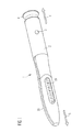
Figure 1 schematically shows a perspective side view of a drug delivery device, -
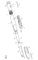
Figure 2 schematically shows an exploded view of the drug delivery device ofFigure 1 , -
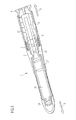
Figure 3 schematically shows a sectional side view of the drug delivery device ofFigure 1 before a dose setting operation takes place, -
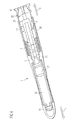
Figure 4 schematically shows a sectional side view of the drug delivery device ofFigure 1 before a dose delivery operation takes place, -
Figure 5A schematically shows a perspective side view of a dose button, -
Figure 5B schematically shows a sectional side view of the dose button ofFigure 5A , -
Figure 6A schematically shows a perspective side view of a housing, -
Figure 6B schematically shows a sectional side view of the housing ofFigure 6A , -
Figure 7A schematically shows a perspective side view of a drive mechanism, -
Figure 7B schematically shows a further perspective side view of the drive mechanism ofFigure 7A . - Like elements, elements of the same kind and identically acting elements may be provided with the same reference numerals in the figures.
- In
Figures 1 and2 adrug delivery device 1 is shown. Thedrug delivery device 1 comprises ahousing 2. Thedrug delivery device 1 and thehousing 2 have a distal end and a proximal end. The distal end is indicated byarrow 5. The proximal end is indicated by arrow 6. The term "distal end" designates that end of thedrug delivery device 1 or a component thereof which is or is to be arranged closest to a dispensing end of thedrug delivery device 1. The term "proximal end" designates that end of thedevice 1 or a component thereof which is or is to be arranged furthest away from the dispensing end of thedevice 1. The distal end and the proximal end are spaced apart from one another in the direction of an axis. The axis may be the main longitudinal axis of thedevice 1. - The
drug delivery device 1 comprises acartridge 15. Thecartridge 15 is permanently or releasably retained within acartridge holder 14. Thecartridge holder 14 stabilizes thecartridge 15 mechanically. Thecartridge holder 14 may be, permanently or releasably, attached to thehousing 2 of thedrug delivery device 1. Alternatively, thecartridge 15 may be permanently or releasably fixed to thehousing 2. In this case, thecartridge holder 14 may be redundant. - The
cartridge 15 contains adrug 16, preferably a plurality of doses of thedrug 16. Thedrug 16 may be a fluid drug. The term "drug", as used herein, preferably means a pharmaceutical formulation containing at least one pharmaceutically active compound,
wherein in one embodiment the pharmaceutically active compound has a molecular weight up to 1500 Da and/or is a peptide, a proteine, a polysaccharide, a vaccine, a DNA, a RNA, an enzyme, an antibody, a hormone or an oligonucleotide, or a mixture of the above-mentioned pharmaceutically active compound,
wherein in a further embodiment the pharmaceutically active compound is useful for the treatment and/or prophylaxis of diabetes mellitus or complications associated with diabetes mellitus such as diabetic retinopathy, thromboembolism disorders such as deep vein or pulmonary thromboembolism, acute coronary syndrome (ACS), angina, myocardial infarction, cancer, macular degeneration, inflammation, hay fever, atherosclerosis and/or rheumatoid arthritis,
wherein in a further embodiment the pharmaceutically active compound comprises at least one peptide for the treatment and/or prophylaxis of diabetes mellitus or complications associated with diabetes mellitus such as diabetic retinopathy,
wherein in a further embodiment the pharmaceutically active compound comprises at least one human insulin or a human insulin analogue or derivative, glucagon-like peptide (GLP-1) or an analogue or derivative thereof, or exedin-3 or exedin-4 or an analogue or derivative of exedin-3 or exedin-4. - Insulin analogues are for example Gly(A21), Arg(B31), Arg(B32) human insulin; Lys(B3), Glu(B29) human insulin; Lys(B28), Pro(B29) human insulin; Asp(B28) human insulin; human insulin, wherein proline in position B28 is replaced by Asp, Lys, Leu, Val or Ala and wherein in position B29 Lys may be replaced by Pro; Ala(B26) human insulin; Des(B28-B30) human insulin; Des(B27) human insulin and Des(B30) human insulin.
- Insulin derivates are for example B29-N-myristoyl-des(B30) human insulin; B29-N-palmitoyl-des(B30) human insulin; B29-N-myristoyl human insulin; B29-N-palmitoyl human insulin; B28-N-myristoyl LysB28ProB29 human insulin; B28-N-palmitoyl-LysB28ProB29 human insulin; B30-N-myristoyl-ThrB29LysB30 human insulin; B30-N-palmitoyl- ThrB29LysB30 human insulin; B29-N-(N-palmitoyl-Y-glutamyl)-des(B30) human insulin; B29-N-(N-lithocholyl-Y-glutamyl)-des(B30) human insulin; B29-N-(ω-carboxyheptadecanoyl)-des(B30) human insulin and B29-N-(ω-carboxyheptadecanoyl) human insulin.
- Exendin-4 for example means Exendin-4(1-39), a peptide of the sequence H-His-Gly-Glu-Gly-Thr-Phe-Thr-Ser-Asp-Leu-Ser-Lys-Gln-Met-Glu-Glu-Glu-Ala-Val-Arg-Leu-Phe-Ile-Glu-Trp-Leu-Lys-Asn-Gly-Gly-Pro-Ser-Ser-Gly-Ala-Pro-Pro-Pro-Ser-NH2.
- Exendin-4 derivatives are for example selected from the following list of compounds:
- H-(Lys)4-des Pro36, des Pro37 Exendin-4(1-39)-NH2,
- H-(Lys)5-des Pro36, des Pro37 Exendin-4(1-39)-NH2,
- des Pro36 [Asp28] Exendin-4(1-39),
- des Pro36 [lsoAsp28] Exendin-4(1-39),
- des Pro36 [Met(O)14, Asp28] Exendin-4(1-39),
- des Pro36 [Met(O)14, lsoAsp28] Exendin-4(1-39),
- des Pro36 [Trp(02)25, Asp28] Exendin-4(1-39),
- des Pro36 [Trp(02)25, IsoAsp28] Exendin-4(1-39),
- des Pro36 [Met(O)14 Trp(02)25, Asp28] Exendin-4(1-39),
- des Pro36 [Met(O)14 Trp(02)25, IsoAsp28] Exendin-4(1-39); or
- des Pro36 [Asp28] Exendin-4(1-39),
- des Pro36 [IsoAsp28] Exendin-4(1-39),
- des Pro36 [Met(O)14, Asp28] Exendin-4(1-39),
- des Pro36 [Met(O)14, IsoAsp28] Exendin-4(1-39),
- des Pro36 [Trp(02)25, Asp28] Exendin-4(1-39),
- des Pro36 [Trp(02)25, IsoAsp28] Exendin-4(1-39),
- des Pro36 [Met(O)14 Trp(02)25, Asp28] Exendin-4(1-39),
- des Pro36 [Met(O)14 Trp(02)25, IsoAsp28] Exendin-4(1-39),
- wherein the group -Lys6-NH2 may be bound to the C-terminus of the Exendin-4 derivative;
- or an Exendin-4 derivative of the sequence
- H-(Lys)6-des Pro36 [Asp28] Exendin-4(1-39)-Lys6-NH2,
- des Asp28 Pro36, Pro37, Pro38Exendin-4(1-39)-NH2,
- H-(Lys)6-des Pro36, Pro38 [Asp28] Exendin-4(1-39)-NH2,
- H-Asn-(Glu)5des Pro36, Pro37, Pro38 [Asp28] Exendin-4(1-39)-NH2,
- des Pro36, Pro37, Pro38 [Asp28] Exendin-4(1-39)-(Lys)6-NH2,
- H-(Lys)6-des Pro36, Pro37, Pro38 [Asp28] Exendin-4(1-39)-(Lys)6-NH2,
- H-Asn-(Glu)5-des Pro36, Pro37, Pro38 [Asp28] Exendin-4(1-39)-(Lys)6-NH2,
- H-(Lys)6-des Pro36 [Trp(02)25, Asp28] Exendin-4(1-39)-Lys6-NH2,
- H-des Asp28 Pro36, Pro37, Pro38 [Trp(02)25] Exendin-4(1-39)-NH2,
- H-(Lys)6-des Pro36, Pro37, Pro38 [Trp(02)25, Asp28] Exendin-4(1-39)-NH2,
- H-Asn-(Glu)5-des Pro36, Pro37, Pro38 [Trp(02)25, Asp28] Exendin-4(1-39)-NH2,
- des Pro36, Pro37, Pro38 [Trp(02)25, Asp28] Exendin-4(1-39)-(Lys)6-NH2,
- H-(Lys)6-des Pro36, Pro37, Pro38 [Trp(02)25, Asp28] Exendin-4(1-39)-(Lys)6-NH2,
- H-Asn-(Glu)5-des Pro36, Pro37, Pro38 [Trp(02)25, Asp28] Exendin-4(1-39)-(Lys)6-NH2,
- H-(Lys)6-des Pro36 [Met(O)14, Asp28] Exendin-4(1-39)-Lys6-NH2,
- des Met(O)14 Asp28 Pro36, Pro37, Pro38 Exendin-4(1-39)-NH2,
- H-(Lys)6-desPro36, Pro37, Pro38 [Met(O)14, Asp28] Exendin-4(1-39)-NH2,
- H-Asn-(Glu)5-des Pro36, Pro37, Pro38 [Met(O)14, Asp28] Exendin-4(1-39)-NH2,
- des Pro36, Pro37, Pro38 [Met(O)14, Asp28] Exendin-4(1-39)-(Lys)6-NH2,
- H-(Lys)6-des Pro36, Pro37, Pro38 [Met(O)14, Asp28] Exendin-4(1-39)-(Lys)6-NH2,
- H-Asn-(Glu)5 des Pro36, Pro37, Pro38 [Met(O)14, Asp28] Exendin-4(1-39)-(Lys)6-NH2,
- H-Lys6-des Pro36 [Met(O)14, Trp(02)25, Asp28] Exendin-4(1-39)-Lys6-NH2,
- H-des Asp28 Pro36, Pro37, Pro38 [Met(O)14, Trp(02)25] Exendin-4(1-39)-NH2,
- H-(Lys)6-des Pro36, Pro37, Pro38 [Met(O)14, Asp28] Exendin-4(1-39)-NH2,
- H-Asn-(Glu)5-des Pro36, Pro37, Pro38 [Met(O)14, Trp(02)25, Asp28] Exendin-4(1-39)-NH2,
- des Pro36, Pro37, Pro38 [Met(O)14, Trp(02)25, Asp28] Exendin-4(1-39)-(Lys)6-NH2,
- H-(Lys)6-des Pro36, Pro37, Pro38 [Met(O)14, Trp(02)25, Asp28] Exendin-4(S1-39)-(Lys)6-NH2,
- H-Asn-(Glu)5-des Pro36, Pro37, Pro38 [Met(O)14, Trp(02)25, Asp28] Exendin-4(1-39)-(Lys)6-NH2;
- Hormones are for example hypophysis hormones or hypothalamus hormones or regulatory active peptides and their antagonists as listed in Rote Liste, ed. 2008, Chapter 50, such as Gonadotropine (Follitropin, Lutropin, Choriongonadotropin, Menotropin), Somatropine (Somatropin), Desmopressin, Terlipressin, Gonadorelin, Triptorelin, Leuprorelin, Buserelin, Nafarelin, Goserelin.
- A polysaccharide is for example a glucosaminoglycane, a hyaluronic acid, a heparin, a low molecular weight heparin or an ultra low molecular weight heparin or a derivative thereof, or a sulphated, e.g. a poly-sulphated form of the above-mentioned polysaccharides, and/or a pharmaceutically acceptable salt thereof. An example of a pharmaceutically acceptable salt of a poly-sulphated low molecular weight heparin is enoxaparin sodium.
- Pharmaceutically acceptable salts are for example acid addition salts and basic salts. Acid addition salts are e.g. HCl or HBr salts. Basic salts are e.g. salts having a cation selected from alkali or alkaline, e.g. Na+, or K+, or Ca2+, or an ammonium ion N+(R1)(R2)(R3)(R4), wherein R1 to R4 independently of each other mean: hydrogen, an optionally substituted C1-C6-alkyl group, an optionally substituted C2-C6-alkenyl group, an optionally substituted C6-C10-aryl group, or an optionally substituted C6-C10-heteroaryl group. Further examples of pharmaceutically acceptable salts are described in "Remington's Pharmaceutical Sciences" 17. ed. Alfonso R. Gennaro (Ed.), Mark Publishing Company, Easton, Pa., U.S.A., 1985 and in Encyclopedia of Pharmaceutical Technology.
- Pharmaceutically acceptable solvates are for example hydrates.
- The
cartridge 15 has anoutlet 18. Theoutlet 18 is covered by amembrane 21. For delivery of thedrug 16, themembrane 21 may be penetrated, for example pierced, e.g. by a needle assembly (not explicitly shown). A bung 17 is slideably retained within thecartridge 15. The bung 17 seals thecartridge 15 proximally. Movement of the bung 17 in the distal direction with respect to thecartridge 15 causes thedrug 16 to be dispensed from thecartridge 15 through theoutlet 18. - The
device 1 comprises adose button 4. Thedose button 4 is moveable in the proximal direction, preferably from a distal end position into a dose delivery position, for setting a dose of thedrug 16. Thedose button 4 is moveable in the distal direction, preferably from the dose delivery position back into the distal end position, for dispensing the set dose. Thedose button 4 may comprise or may be embodied as a sleeve. - The
dose button 4 comprises an interaction face 22 (see alsoFigures 5A and 5B ). Theinteraction face 22 is arranged in the proximal section of thedose button 4. Theinteraction face 22 may be formed by a flange extending circumferentially around an outer surface of thedose button 4, for example. Mechanical cooperation of theinteraction face 22 and aproximal face 23 of the housing 2 (see alsoFigures 6A and 6B ) may prevent further movement of thedose button 4 in the distal direction when thedose button 4 is in the distal end position. Accordingly, theinteraction face 22 of thedose button 4 may provide a distal end stop for thedose button 4. - The device comprises a drive mechanism 24 (see
Figures 7A and 7B ). Thedrive mechanism 24 comprises adrive member 12. Thedrive member 12 and thedose button 4 are secured to each other to prevent rotational and/or axial movement between one another. Thedrive member 12 comprises engaging means 25 (seeFigures 7A and 7B ). Engaging means 25 may comprise a rib, preferably a plurality of ribs. Thedose button 4 comprises mating engaging means 26 (seeFigures 5A and 5B ). Engaging means 25 may comprise a nut, preferably a plurality of nuts. Movement of thedose button 4 is converted into movement of thedrive member 12 with respect to thehousing 2 by mechanical cooperation of the engagingmeans 25 and themating engaging means 26. Thedrive member 12 transfers movement of thedose button 4 into movement of apiston rod 13 for dispensing the dose by mechanical cooperation of thedrive member 12 and thepiston rod 13. Thedrive member 12 extends about the piston rod 13 (seeFigures 7A and 7B ). - The
piston rod 13 is designed to operate through thehousing 2 of thedrug delivery device 1. Thepiston rod 13 is designed to transfer axial movement through thedrug delivery device 1 for the purpose of delivering thedrug 16. Thepiston rod 13 is configured to be axially displaced in the distal direction for delivering the dose. Preferably, thepiston rod 13 is prevented from being axially displaced in the proximal direction when setting a dose of thedrug 4 by mechanical cooperation with a fixed part of thedrive mechanism 24. A bearingsurface 13A located at the distal end of thepiston rod 13 is disposed to abut the proximal face of thebung 17. - The fixed part of the
drive mechanism 24 comprises a locking member 27 (seeFigure 7B ). A mating locking member 28 (seeFigure 6B ) may be provided on theinner surface 11 of thehousing 2. Movement of the fixed part with respect to thehousing 2 may be prevented by mechanical cooperation of lockingmember 27 andmating locking member 28. The fixed part mechanically cooperates with thedrive member 12, e.g. by providing teeth for mechanical interaction with a gear wheel of thedrive member 12. More details concerning thedrive mechanism 24 can be taken from documentWO 08058666 A1 - The
device 1 comprises acap 19. Thecap 19 is configured to cover the distal end of thedevice 1. Thecap 19 comprises awindow aperture 20. A dosing scale provided on thecartridge holder 14 and/or thecartridge 15 may be visible through the window aperture. - The
device 1 comprises a resilient setting member 7. The resilient setting member 7 may be spring, e.g. a compression spring. The resilient setting member 7 exerts a force, in particular a proximally directed force, onto thedose button 4. An energy stored in the resilient setting member 7, either during assembly or during a dose delivery operation, may be used for driving thedose button 4 proximally for setting a dose of thedrug 16, which is explained later on in more detail. The resilient setting member 7 is provided between adistal face 8 of thedose button 4 and a bearingmember 9. The bearingmember 9 is provided on aninner surface 11 of the housing 2 (see, in particularFigures 5A, 5B andFigures 6A, 6B ). The bearingmember 8 may be a protrusion or a nut provided circumferentially on theinner surface 11 of thehousing 2. - The
device 1 comprises a blocking member 3. The blocking member 3 is configured to mechanically interact with thehousing 2. The blocking member 3 is adapted and arranged to be releasably coupled to thehousing 2. Thehousing 2 comprises an engagement means 10, e.g. an opening. Said engagement means 10 is configured to receive the blocking member 3 for coupling the blocking member 3 and thehousing 2. Thus, an interlock of engagement means 10 and blocking member 3 is formed. The blocking member 3 and thehousing 2 are coupled to one another when thedose button 4 is in the distal end position (seeFigure 3 ). - When the blocking member 3 is coupled to the
housing 2, movement of thedose button 4 with respect to thehousing 2, in particular movement driven by the energy stored in the resilient setting member 7, is prevented. When the blocking member 3 and thehousing 2 are decoupled, a dose setting movement of thedose button 4 with respect to thehousing 2 in the proximal direction is allowed. Furthermore, when the blocking member 3 and thehousing 2 are decoupled, a dose delivery movement of thedose button 4 with respect to thehousing 2 in the distal direction, in particular towards a distal end position is allowed. Operation of setting and delivering a dose and, in particular, operation of the blocking member 3 is described in detail in connection withFigures 3 and4 . - The blocking member 3 is prevented from axial and rotational movement with respect to the
dose button 4. The blocking member 3 is connected to or is integrated in thedose button 4. The blocking member 3 is externally actuatable, in particular user actuatable. The blocking member 3 is moveable with respect to thehousing 2 for coupling and/or decoupling the blocking member 3 and thehousing 2. In particular, the blocking member 3 is moveable in the radial direction with respect to thehousing 2. The blocking member 3 is moveable in the radial inward direction with respect to thehousing 2, preferably by the user, for decoupling the blocking member 3 and thehousing 2. The blocking member 3 is moveable in the radial outward direction with respect to thehousing 2 for coupling the blocking member 3 and thehousing 2, thus preventing movement of thedose button 4 with respect to thehousing 2. - The blocking member 3 comprises a resilient member or a resiliently mounted member. A resilient force provided by the resilient member or the resiliently mounted member automatically moves the blocking member 3 in the radial outward direction with respect to the
housing 2 for coupling the blocking member 3 to thehousing 2 when thedose button 4 is in the distal end position, which is explained later on in more detail. The blocking member 3 comprises aknob 29. Theknob 29 is connected to thedose button 4 by means of a flexible web 30 (seeFigure 5A ). When thedose button 4 is in the distal end position, theknob 29 protrudes from the outer surface of thehousing 2. Accordingly, the blocking member 3 is accessible from the outside of thedevice 1 when thedose button 4 is in the distal end position. -
Figure 3 schematically shows a sectional side view of the drug delivery device ofFigure 1 before a dose setting operation takes place. -
Figure 4 schematically shows a sectional side view of the drug delivery device ofFigure 1 before a dose delivery operation takes place. - In an initial state of the
device 1, e.g. the state of thedevice 1 when thedevice 1 is supplied to the user as assembled by the manufacturer, thedose button 4 is positioned in the distal end position as shown inFigure 3 . Thehousing 2 and the blocking member 3 are coupled to one another due to mechanical cooperation of the blocking member 3 and the engagement means 10 and, thus, movement of thedose button 4 with respect to thehousing 2 is prevented. The resilient setting member 7 is biased, e.g. compressed. - For setting a dose, the user presses
knob 29 and, thus, moves the blocking member 3 radially inwardly with respect to thehousing 2. Thereby, the blocking member 3 decouples from thehousing 2, in particular from the engagement means 10. When the blocking member 3 is moved radially inwardly, an energy is stored in the blocking member 3. When the blocking member 3 was moved radially inwardly, the blocking member 3 provides a resilient force. The force is directed radially outwardly with respect to thehousing 2. - When the blocking member 3 and the
housing 2 are decoupled, thedose button 4 is moveable with respect to thehousing 2. Accordingly, the resilient setting member 7 is allowed to relax, thereby moving thedose button 4 proximally out of the distal end position and into the dose delivery position (seeFigure 4 ). A proximal end stop (not explicitly shown) may be provided in the housing, e.g. in a proximal section of thehousing 2, to prevent movement of thedose button 4 in the proximal direction beyond the dose delivery position by mechanical cooperation of the proximal end stop and thedose button 4. - When the
dose button 4 is out of the distal end position, the blocking member 3 is prevented from moving radially outwardly driven by the energy stored in the blocking member 3 due to mechanical cooperation of the blocking member 3 and theinner surface 11 of thehousing 2. When thedose button 4 is out of the distal end position, the blocking member 3 may be guided along a guide track arranged on theinner surface 11 of the housing 2 (not explicitly shown). - For delivering the set dose, the user pushes onto the
dose button 4, thereby moving thedose button 4 distally. Thereby, the resilient setting member 7 is compressed. Thedose button 4 is moved distally until theinteraction face 22 of thedose button 4 abuts theproximal face 23 of thehousing 2. When theinteraction face 22 of thedose button 4 abuts theproximal face 23 of thehousing 2, thedose button 4 is in the distal end position and the set dose of thedrug 16 was dispensed completely from thedevice 1. - When the
dose button 4 is in the distal end position, the blocking member 3 and the engagement means 10 axially overlap. Accordingly, due to the energy stored in the blocking member 3, the blocking member 3 is automatically moved radially outwardly such that the blocking member 3 mechanically cooperates with the engagement means 10 and such that thedose button 4 is prevented from proximal movement with respect to thehousing 2 until the user actuates again the blocking member 3 for setting a subsequent dose of thedrug 16. - The
drug delivery device 1 may be a pen-type device, in particular a pen-type injector. Thedevice 1 may be a disposable or a re-usable device. Thedevice 1 may be especially suitable for dispensing fixed doses of thedrug 16, e.g. doses the size of which may not be varied by the user. Accordingly, thedose button 4 may be moved by the same distance in the proximal direction with respect to thehousing 2 during each dose setting operation. -
- 1
- drug delivery device
- 2
- housing
- 3
- blocking member
- 4
- dose button
- 5
- arrow
- 6
- arrow
- 7
- resilient setting member
- 8
- distal face of dose button
- 9
- bearing member
- 10
- engagement means
- 11
- inner surface of housing
- 12
- drive member
- 13
- piston rod
- 13A
- bearing surface
- 14
- cartridge holder
- 15
- cartridge
- 16
- drug
- 17
- bung
- 18
- outlet
- 19
- cap
- 20
- window aperture
- 21
- membrane
- 22
- interaction face of dose button
- 23
- proximal face of housing
- 24
- drive mechanism
- 25
- engaging means
- 26
- mating engaging means
- 27
- locking member
- 28
- mating locking member
- 29
- knob
- 30
- web
Claims (15)
- An assembly for a drug delivery device (1), comprising- a housing (2) having a distal end and a proximal end,- a dose button (4) configured to be moved with respect to the housing (2) for setting and delivering a dose of a drug from the device (1),- a blocking member (3),wherein the blocking member (3) is adapted and arranged to be releasably coupled to the housing (2) such that, when the blocking member (3) is coupled to the housing (2), movement of the dose button (4) with respect to the housing (2) is prevented.
- The assembly according to claim 1,
wherein, when the blocking member (3) and the housing (2) are decoupled, a dose setting movement of the dose button (4) with respect to the housing (2) in the proximal direction from a distal end position into a dose delivery position is allowed. - The assembly according to claim 2,
wherein the blocking member (3) is decoupled from the housing (2) when the dose button (4) is out of the distal end position. - The assembly according to any of the previous claims,
wherein the blocking member (3) is moveable with respect to the housing (2) for coupling and/or decoupling the blocking member (3) and the housing (2). - The assembly according to claim 4,
wherein the blocking member (3) is moveable in the radial direction with respect to the housing (2), and wherein the blocking member (3) is moved in the radial inward direction with respect to the housing (2) for decoupling the blocking member (3) and the housing (2). - The assembly according to claim 5,
wherein the blocking member (3) is a resilient member or a resiliently mounted member configured such that a resilient force provided by the resilient member or the resiliently mounted member moves the blocking member (3) in the radial outward direction with respect to the housing (2) for coupling the blocking member (3) to the housing (2) when the dose button (4) is moved in the distal direction for delivering the set dose. - The assembly according to any of the previous claims,
wherein the blocking member (3) is connected to or is integrated in the dose button (4). - The assembly according to any of the previous claims,
wherein the blocking member (3) is externally actuatable. - The assembly according to any of the previous claims,
further comprising a resilient setting member (7), wherein the assembly is adapted and arranged to use an energy stored in the resilient setting member (7) to drive the dose button (4) proximally for setting a dose of the drug. - The assembly according to claim 9,
wherein the resilient setting member (7) is arranged between a distal face (8) of the dose button (4) and a bearing member (9) provided on an inner surface (11) of the housing (2). - The assembly according to any of claims 2 to 10,
wherein the housing (2) comprises an engagement means (10) which is adapted and arranged to mechanically cooperate with the blocking member (3) when the dose button (4) is in the distal end position. - The assembly according to claim 11,
wherein the engagement means (10) comprises an opening in the housing (2) which is configured to receive the blocking member (3). - The assembly according to any of the previous claims,
comprising a drive member (12) which is moveable in the proximal direction with respect to the housing (2) for setting a dose of the drug and moveable in the distal direction with respect to the housing (2) for dispensing the set dose, wherein movement of the dose button (4) is converted into movement of the drive member (12) with respect to the housing (2) by mechanical cooperation of the dose button (4) and the drive member (12). - The assembly according to claim 13,
comprising a piston rod (13) adapted to operate through the housing (2) and to transfer a force in the distal direction from the dose button (4), wherein movement of the dose button (4) in the distal direction with respect to the housing (2) is converted into movement of the piston rod (13) in the distal direction by means of mechanical interaction of the drive member (12) and the piston rod (13) for dispensing the dose. - A drug delivery device (1) comprising the assembly according to any of claims 1 to 14,
wherein the device (1) comprises a cartridge (15) holding a drug (16).
Priority Applications (3)
| Application Number | Priority Date | Filing Date | Title |
|---|---|---|---|
| DK10193752.2T DK2460551T3 (en) | 2010-12-06 | 2010-12-06 | Drug delivery device with dose knob lock arrangement |
| EP10193752.2A EP2460551B1 (en) | 2010-12-06 | 2010-12-06 | Drug delivery device with locking arrangement for dose button |
| US13/311,423 US8721604B2 (en) | 2010-12-06 | 2011-12-05 | Assembly for a drug delivery device and drug delivery device |
Applications Claiming Priority (1)
| Application Number | Priority Date | Filing Date | Title |
|---|---|---|---|
| EP10193752.2A EP2460551B1 (en) | 2010-12-06 | 2010-12-06 | Drug delivery device with locking arrangement for dose button |
Publications (2)
| Publication Number | Publication Date |
|---|---|
| EP2460551A1 true EP2460551A1 (en) | 2012-06-06 |
| EP2460551B1 EP2460551B1 (en) | 2016-04-27 |
Family
ID=43877061
Family Applications (1)
| Application Number | Title | Priority Date | Filing Date |
|---|---|---|---|
| EP10193752.2A Active EP2460551B1 (en) | 2010-12-06 | 2010-12-06 | Drug delivery device with locking arrangement for dose button |
Country Status (3)
| Country | Link |
|---|---|
| US (1) | US8721604B2 (en) |
| EP (1) | EP2460551B1 (en) |
| DK (1) | DK2460551T3 (en) |
Citations (7)
| Publication number | Priority date | Publication date | Assignee | Title |
|---|---|---|---|---|
| DE3900926A1 (en) * | 1988-02-08 | 1989-08-17 | Disetronic Ag | Injection device |
| EP0615762A1 (en) * | 1993-03-15 | 1994-09-21 | Eli Lilly And Company | Dosing seringe |
| WO1996007443A1 (en) * | 1994-09-08 | 1996-03-14 | Owen Mumford Limited | Improvements relating to injection devices |
| WO1997017096A1 (en) * | 1995-11-09 | 1997-05-15 | Disetronic Licensing Ag | Injection device |
| WO1999003522A1 (en) * | 1997-07-18 | 1999-01-28 | Disetronic Licensing Ag | System for locking a dosing button in a device for the administration of a product to be injected |
| US20050137571A1 (en) * | 2002-06-28 | 2005-06-23 | Edgar Hommann | Administering apparatus with a resettable activating block |
| EP1923083A1 (en) | 2006-11-17 | 2008-05-21 | Sanofi-Aventis Deutschland GmbH | Drive mechanisms for use in drug delivery devices |
Family Cites Families (9)
| Publication number | Priority date | Publication date | Assignee | Title |
|---|---|---|---|---|
| US5584815A (en) * | 1993-04-02 | 1996-12-17 | Eli Lilly And Company | Multi-cartridge medication injection device |
| DE59510404D1 (en) * | 1994-05-30 | 2002-11-07 | B D Medico S A R L | INJECTION DEVICE |
| WO1996005878A1 (en) * | 1994-08-24 | 1996-02-29 | Eli Lilly Japan Kabushiki Kaisha | Injection apparatus |
| DE10046279A1 (en) * | 2000-09-19 | 2002-04-04 | Disetronic Licensing Ag | Device for the dosed administration of an injectable product |
| DE102005023824A1 (en) * | 2005-05-24 | 2006-12-07 | Tecpharma Licensing Ag | Dosing device for an injection device |
| DE102007026555A1 (en) * | 2007-06-08 | 2008-12-11 | Tecpharma Licensing Ag | Adjustment and Aufziehfixierung after distribution of the last dose |
| US8728043B2 (en) * | 2009-06-01 | 2014-05-20 | Sanofi-Aventis Deutschland Gmbh | Drive mechanism for a drug delivery device |
| TWI530306B (en) * | 2009-06-02 | 2016-04-21 | 賽諾菲阿凡提斯德意志有限公司 | Drug delivery device assembly and drug delivery device |
| DK2560708T3 (en) * | 2010-04-23 | 2018-01-22 | Sanofi Aventis Deutschland | CODED PATTERN FITTING |
-
2010
- 2010-12-06 DK DK10193752.2T patent/DK2460551T3/en active
- 2010-12-06 EP EP10193752.2A patent/EP2460551B1/en active Active
-
2011
- 2011-12-05 US US13/311,423 patent/US8721604B2/en not_active Expired - Fee Related
Patent Citations (8)
| Publication number | Priority date | Publication date | Assignee | Title |
|---|---|---|---|---|
| DE3900926A1 (en) * | 1988-02-08 | 1989-08-17 | Disetronic Ag | Injection device |
| EP0615762A1 (en) * | 1993-03-15 | 1994-09-21 | Eli Lilly And Company | Dosing seringe |
| WO1996007443A1 (en) * | 1994-09-08 | 1996-03-14 | Owen Mumford Limited | Improvements relating to injection devices |
| WO1997017096A1 (en) * | 1995-11-09 | 1997-05-15 | Disetronic Licensing Ag | Injection device |
| WO1999003522A1 (en) * | 1997-07-18 | 1999-01-28 | Disetronic Licensing Ag | System for locking a dosing button in a device for the administration of a product to be injected |
| US20050137571A1 (en) * | 2002-06-28 | 2005-06-23 | Edgar Hommann | Administering apparatus with a resettable activating block |
| EP1923083A1 (en) | 2006-11-17 | 2008-05-21 | Sanofi-Aventis Deutschland GmbH | Drive mechanisms for use in drug delivery devices |
| WO2008058666A1 (en) | 2006-11-17 | 2008-05-22 | Sanofi-Aventis Deutschland Gmbh | Improvements in and relating to drive mechanisms suitable for use in drug delivery devices |
Non-Patent Citations (1)
| Title |
|---|
| "Remington's Pharmaceutical Sciences", vol. 17, 1985, MARK PUBLISHING COMPANY |
Also Published As
| Publication number | Publication date |
|---|---|
| US8721604B2 (en) | 2014-05-13 |
| US20120150127A1 (en) | 2012-06-14 |
| DK2460551T3 (en) | 2016-08-15 |
| EP2460551B1 (en) | 2016-04-27 |
Similar Documents
| Publication | Publication Date | Title |
|---|---|---|
| US8740860B2 (en) | Assembly for a drug delivery device and drug delivery device | |
| US11298464B2 (en) | Assembly for a drug delivery device and drug delivery device | |
| EP2531241B1 (en) | Assembly for a drug delivery device and drug delivery device | |
| EP2437830B2 (en) | Assembly for a drug delivery device and drug delivery device | |
| US20120325865A1 (en) | Drug delivery device | |
| EP2579920B1 (en) | Assembly for a drug delivery device and drug delivery device | |
| WO2011039209A1 (en) | Assembly and piston rod for a drug delivery device | |
| EP2482889B1 (en) | Assembly for a drug delivery device | |
| US20120204662A1 (en) | Drive Mechanism and Drug Delivery Device | |
| US9533104B2 (en) | Assembly for a drug delivery device and piston rod | |
| EP2460551B1 (en) | Drug delivery device with locking arrangement for dose button | |
| HK1175415B (en) | Assembly for a drug delivery device and drug delivery device | |
| HK1175415A (en) | Assembly for a drug delivery device and drug delivery device | |
| HK1178826B (en) | Assembly for a drug delivery device and drug delivery device |
Legal Events
| Date | Code | Title | Description |
|---|---|---|---|
| PUAI | Public reference made under article 153(3) epc to a published international application that has entered the european phase |
Free format text: ORIGINAL CODE: 0009012 |
|
| AK | Designated contracting states |
Kind code of ref document: A1 Designated state(s): AL AT BE BG CH CY CZ DE DK EE ES FI FR GB GR HR HU IE IS IT LI LT LU LV MC MK MT NL NO PL PT RO RS SE SI SK SM TR |
|
| AX | Request for extension of the european patent |
Extension state: BA ME |
|
| 17P | Request for examination filed |
Effective date: 20121206 |
|
| 17Q | First examination report despatched |
Effective date: 20130322 |
|
| GRAP | Despatch of communication of intention to grant a patent |
Free format text: ORIGINAL CODE: EPIDOSNIGR1 |
|
| RIC1 | Information provided on ipc code assigned before grant |
Ipc: A61M 5/24 20060101AFI20150622BHEP Ipc: A61M 5/315 20060101ALN20150622BHEP |
|
| INTG | Intention to grant announced |
Effective date: 20150708 |
|
| GRAS | Grant fee paid |
Free format text: ORIGINAL CODE: EPIDOSNIGR3 |
|
| GRAA | (expected) grant |
Free format text: ORIGINAL CODE: 0009210 |
|
| AK | Designated contracting states |
Kind code of ref document: B1 Designated state(s): AL AT BE BG CH CY CZ DE DK EE ES FI FR GB GR HR HU IE IS IT LI LT LU LV MC MK MT NL NO PL PT RO RS SE SI SK SM TR |
|
| AX | Request for extension of the european patent |
Extension state: BA ME |
|
| REG | Reference to a national code |
Ref country code: GB Ref legal event code: FG4D |
|
| REG | Reference to a national code |
Ref country code: CH Ref legal event code: EP |
|
| REG | Reference to a national code |
Ref country code: AT Ref legal event code: REF Ref document number: 794040 Country of ref document: AT Kind code of ref document: T Effective date: 20160515 |
|
| REG | Reference to a national code |
Ref country code: IE Ref legal event code: FG4D |
|
| REG | Reference to a national code |
Ref country code: DE Ref legal event code: R096 Ref document number: 602010032788 Country of ref document: DE |
|
| REG | Reference to a national code |
Ref country code: DK Ref legal event code: T3 Effective date: 20160812 |
|
| REG | Reference to a national code |
Ref country code: SE Ref legal event code: TRGR |
|
| REG | Reference to a national code |
Ref country code: LT Ref legal event code: MG4D |
|
| REG | Reference to a national code |
Ref country code: NL Ref legal event code: MP Effective date: 20160427 |
|
| REG | Reference to a national code |
Ref country code: AT Ref legal event code: MK05 Ref document number: 794040 Country of ref document: AT Kind code of ref document: T Effective date: 20160427 |
|
| PG25 | Lapsed in a contracting state [announced via postgrant information from national office to epo] |
Ref country code: NL Free format text: LAPSE BECAUSE OF FAILURE TO SUBMIT A TRANSLATION OF THE DESCRIPTION OR TO PAY THE FEE WITHIN THE PRESCRIBED TIME-LIMIT Effective date: 20160427 |
|
| PG25 | Lapsed in a contracting state [announced via postgrant information from national office to epo] |
Ref country code: PL Free format text: LAPSE BECAUSE OF FAILURE TO SUBMIT A TRANSLATION OF THE DESCRIPTION OR TO PAY THE FEE WITHIN THE PRESCRIBED TIME-LIMIT Effective date: 20160427 Ref country code: FI Free format text: LAPSE BECAUSE OF FAILURE TO SUBMIT A TRANSLATION OF THE DESCRIPTION OR TO PAY THE FEE WITHIN THE PRESCRIBED TIME-LIMIT Effective date: 20160427 Ref country code: LT Free format text: LAPSE BECAUSE OF FAILURE TO SUBMIT A TRANSLATION OF THE DESCRIPTION OR TO PAY THE FEE WITHIN THE PRESCRIBED TIME-LIMIT Effective date: 20160427 Ref country code: NO Free format text: LAPSE BECAUSE OF FAILURE TO SUBMIT A TRANSLATION OF THE DESCRIPTION OR TO PAY THE FEE WITHIN THE PRESCRIBED TIME-LIMIT Effective date: 20160727 |
|
| PG25 | Lapsed in a contracting state [announced via postgrant information from national office to epo] |
Ref country code: AT Free format text: LAPSE BECAUSE OF FAILURE TO SUBMIT A TRANSLATION OF THE DESCRIPTION OR TO PAY THE FEE WITHIN THE PRESCRIBED TIME-LIMIT Effective date: 20160427 Ref country code: ES Free format text: LAPSE BECAUSE OF FAILURE TO SUBMIT A TRANSLATION OF THE DESCRIPTION OR TO PAY THE FEE WITHIN THE PRESCRIBED TIME-LIMIT Effective date: 20160427 Ref country code: GR Free format text: LAPSE BECAUSE OF FAILURE TO SUBMIT A TRANSLATION OF THE DESCRIPTION OR TO PAY THE FEE WITHIN THE PRESCRIBED TIME-LIMIT Effective date: 20160728 Ref country code: LV Free format text: LAPSE BECAUSE OF FAILURE TO SUBMIT A TRANSLATION OF THE DESCRIPTION OR TO PAY THE FEE WITHIN THE PRESCRIBED TIME-LIMIT Effective date: 20160427 Ref country code: PT Free format text: LAPSE BECAUSE OF FAILURE TO SUBMIT A TRANSLATION OF THE DESCRIPTION OR TO PAY THE FEE WITHIN THE PRESCRIBED TIME-LIMIT Effective date: 20160829 Ref country code: RS Free format text: LAPSE BECAUSE OF FAILURE TO SUBMIT A TRANSLATION OF THE DESCRIPTION OR TO PAY THE FEE WITHIN THE PRESCRIBED TIME-LIMIT Effective date: 20160427 Ref country code: HR Free format text: LAPSE BECAUSE OF FAILURE TO SUBMIT A TRANSLATION OF THE DESCRIPTION OR TO PAY THE FEE WITHIN THE PRESCRIBED TIME-LIMIT Effective date: 20160427 |
|
| PG25 | Lapsed in a contracting state [announced via postgrant information from national office to epo] |
Ref country code: BE Free format text: LAPSE BECAUSE OF FAILURE TO SUBMIT A TRANSLATION OF THE DESCRIPTION OR TO PAY THE FEE WITHIN THE PRESCRIBED TIME-LIMIT Effective date: 20160427 Ref country code: IT Free format text: LAPSE BECAUSE OF FAILURE TO SUBMIT A TRANSLATION OF THE DESCRIPTION OR TO PAY THE FEE WITHIN THE PRESCRIBED TIME-LIMIT Effective date: 20160427 |
|
| REG | Reference to a national code |
Ref country code: DE Ref legal event code: R097 Ref document number: 602010032788 Country of ref document: DE |
|
| PG25 | Lapsed in a contracting state [announced via postgrant information from national office to epo] |
Ref country code: CZ Free format text: LAPSE BECAUSE OF FAILURE TO SUBMIT A TRANSLATION OF THE DESCRIPTION OR TO PAY THE FEE WITHIN THE PRESCRIBED TIME-LIMIT Effective date: 20160427 Ref country code: RO Free format text: LAPSE BECAUSE OF FAILURE TO SUBMIT A TRANSLATION OF THE DESCRIPTION OR TO PAY THE FEE WITHIN THE PRESCRIBED TIME-LIMIT Effective date: 20160427 Ref country code: SK Free format text: LAPSE BECAUSE OF FAILURE TO SUBMIT A TRANSLATION OF THE DESCRIPTION OR TO PAY THE FEE WITHIN THE PRESCRIBED TIME-LIMIT Effective date: 20160427 Ref country code: EE Free format text: LAPSE BECAUSE OF FAILURE TO SUBMIT A TRANSLATION OF THE DESCRIPTION OR TO PAY THE FEE WITHIN THE PRESCRIBED TIME-LIMIT Effective date: 20160427 |
|
| PG25 | Lapsed in a contracting state [announced via postgrant information from national office to epo] |
Ref country code: SM Free format text: LAPSE BECAUSE OF FAILURE TO SUBMIT A TRANSLATION OF THE DESCRIPTION OR TO PAY THE FEE WITHIN THE PRESCRIBED TIME-LIMIT Effective date: 20160427 |
|
| PLBE | No opposition filed within time limit |
Free format text: ORIGINAL CODE: 0009261 |
|
| STAA | Information on the status of an ep patent application or granted ep patent |
Free format text: STATUS: NO OPPOSITION FILED WITHIN TIME LIMIT |
|
| 26N | No opposition filed |
Effective date: 20170130 |
|
| PG25 | Lapsed in a contracting state [announced via postgrant information from national office to epo] |
Ref country code: SI Free format text: LAPSE BECAUSE OF FAILURE TO SUBMIT A TRANSLATION OF THE DESCRIPTION OR TO PAY THE FEE WITHIN THE PRESCRIBED TIME-LIMIT Effective date: 20160427 |
|
| REG | Reference to a national code |
Ref country code: DE Ref legal event code: R119 Ref document number: 602010032788 Country of ref document: DE |
|
| GBPC | Gb: european patent ceased through non-payment of renewal fee |
Effective date: 20161206 |
|
| PG25 | Lapsed in a contracting state [announced via postgrant information from national office to epo] |
Ref country code: MC Free format text: LAPSE BECAUSE OF FAILURE TO SUBMIT A TRANSLATION OF THE DESCRIPTION OR TO PAY THE FEE WITHIN THE PRESCRIBED TIME-LIMIT Effective date: 20160427 |
|
| REG | Reference to a national code |
Ref country code: FR Ref legal event code: ST Effective date: 20170831 |
|
| REG | Reference to a national code |
Ref country code: IE Ref legal event code: MM4A |
|
| PG25 | Lapsed in a contracting state [announced via postgrant information from national office to epo] |
Ref country code: LU Free format text: LAPSE BECAUSE OF NON-PAYMENT OF DUE FEES Effective date: 20161206 Ref country code: FR Free format text: LAPSE BECAUSE OF NON-PAYMENT OF DUE FEES Effective date: 20170102 |
|
| PG25 | Lapsed in a contracting state [announced via postgrant information from national office to epo] |
Ref country code: DE Free format text: LAPSE BECAUSE OF NON-PAYMENT OF DUE FEES Effective date: 20170701 Ref country code: IE Free format text: LAPSE BECAUSE OF NON-PAYMENT OF DUE FEES Effective date: 20161206 Ref country code: GB Free format text: LAPSE BECAUSE OF NON-PAYMENT OF DUE FEES Effective date: 20161206 |
|
| PG25 | Lapsed in a contracting state [announced via postgrant information from national office to epo] |
Ref country code: CY Free format text: LAPSE BECAUSE OF FAILURE TO SUBMIT A TRANSLATION OF THE DESCRIPTION OR TO PAY THE FEE WITHIN THE PRESCRIBED TIME-LIMIT Effective date: 20160427 Ref country code: HU Free format text: LAPSE BECAUSE OF FAILURE TO SUBMIT A TRANSLATION OF THE DESCRIPTION OR TO PAY THE FEE WITHIN THE PRESCRIBED TIME-LIMIT; INVALID AB INITIO Effective date: 20101206 |
|
| PG25 | Lapsed in a contracting state [announced via postgrant information from national office to epo] |
Ref country code: IS Free format text: LAPSE BECAUSE OF FAILURE TO SUBMIT A TRANSLATION OF THE DESCRIPTION OR TO PAY THE FEE WITHIN THE PRESCRIBED TIME-LIMIT Effective date: 20160427 Ref country code: MK Free format text: LAPSE BECAUSE OF FAILURE TO SUBMIT A TRANSLATION OF THE DESCRIPTION OR TO PAY THE FEE WITHIN THE PRESCRIBED TIME-LIMIT Effective date: 20160427 |
|
| PG25 | Lapsed in a contracting state [announced via postgrant information from national office to epo] |
Ref country code: BG Free format text: LAPSE BECAUSE OF FAILURE TO SUBMIT A TRANSLATION OF THE DESCRIPTION OR TO PAY THE FEE WITHIN THE PRESCRIBED TIME-LIMIT Effective date: 20160427 |
|
| PG25 | Lapsed in a contracting state [announced via postgrant information from national office to epo] |
Ref country code: MT Free format text: LAPSE BECAUSE OF NON-PAYMENT OF DUE FEES Effective date: 20161206 |
|
| PG25 | Lapsed in a contracting state [announced via postgrant information from national office to epo] |
Ref country code: AL Free format text: LAPSE BECAUSE OF FAILURE TO SUBMIT A TRANSLATION OF THE DESCRIPTION OR TO PAY THE FEE WITHIN THE PRESCRIBED TIME-LIMIT Effective date: 20160427 |
|
| REG | Reference to a national code |
Ref country code: CH Ref legal event code: U11 Free format text: ST27 STATUS EVENT CODE: U-0-0-U10-U11 (AS PROVIDED BY THE NATIONAL OFFICE) Effective date: 20260101 |
|
| PGFP | Annual fee paid to national office [announced via postgrant information from national office to epo] |
Ref country code: DK Payment date: 20251212 Year of fee payment: 16 |
|
| PGFP | Annual fee paid to national office [announced via postgrant information from national office to epo] |
Ref country code: TR Payment date: 20251203 Year of fee payment: 16 |
|
| PGFP | Annual fee paid to national office [announced via postgrant information from national office to epo] |
Ref country code: SE Payment date: 20251001 Year of fee payment: 16 |
|
| PGFP | Annual fee paid to national office [announced via postgrant information from national office to epo] |
Ref country code: CH Payment date: 20260101 Year of fee payment: 16 |