EP2459856B1 - Exhaust component assemblies with divider plates - Google Patents
Exhaust component assemblies with divider plates Download PDFInfo
- Publication number
- EP2459856B1 EP2459856B1 EP10803968.6A EP10803968A EP2459856B1 EP 2459856 B1 EP2459856 B1 EP 2459856B1 EP 10803968 A EP10803968 A EP 10803968A EP 2459856 B1 EP2459856 B1 EP 2459856B1
- Authority
- EP
- European Patent Office
- Prior art keywords
- exhaust component
- divider plate
- exhaust
- groove
- wall
- Prior art date
- Legal status (The legal status is an assumption and is not a legal conclusion. Google has not performed a legal analysis and makes no representation as to the accuracy of the status listed.)
- Not-in-force
Links
Images






Classifications
-
- F—MECHANICAL ENGINEERING; LIGHTING; HEATING; WEAPONS; BLASTING
- F01—MACHINES OR ENGINES IN GENERAL; ENGINE PLANTS IN GENERAL; STEAM ENGINES
- F01N—GAS-FLOW SILENCERS OR EXHAUST APPARATUS FOR MACHINES OR ENGINES IN GENERAL; GAS-FLOW SILENCERS OR EXHAUST APPARATUS FOR INTERNAL-COMBUSTION ENGINES
- F01N13/00—Exhaust or silencing apparatus characterised by constructional features
- F01N13/08—Other arrangements or adaptations of exhaust conduits
-
- F—MECHANICAL ENGINEERING; LIGHTING; HEATING; WEAPONS; BLASTING
- F01—MACHINES OR ENGINES IN GENERAL; ENGINE PLANTS IN GENERAL; STEAM ENGINES
- F01N—GAS-FLOW SILENCERS OR EXHAUST APPARATUS FOR MACHINES OR ENGINES IN GENERAL; GAS-FLOW SILENCERS OR EXHAUST APPARATUS FOR INTERNAL-COMBUSTION ENGINES
- F01N13/00—Exhaust or silencing apparatus characterised by constructional features
- F01N13/08—Other arrangements or adaptations of exhaust conduits
- F01N13/10—Other arrangements or adaptations of exhaust conduits of exhaust manifolds
-
- F—MECHANICAL ENGINEERING; LIGHTING; HEATING; WEAPONS; BLASTING
- F01—MACHINES OR ENGINES IN GENERAL; ENGINE PLANTS IN GENERAL; STEAM ENGINES
- F01N—GAS-FLOW SILENCERS OR EXHAUST APPARATUS FOR MACHINES OR ENGINES IN GENERAL; GAS-FLOW SILENCERS OR EXHAUST APPARATUS FOR INTERNAL-COMBUSTION ENGINES
- F01N13/00—Exhaust or silencing apparatus characterised by constructional features
- F01N13/18—Construction facilitating manufacture, assembly, or disassembly
- F01N13/1805—Fixing exhaust manifolds, exhaust pipes or pipe sections to each other, to engine or to vehicle body
- F01N13/1811—Fixing exhaust manifolds, exhaust pipes or pipe sections to each other, to engine or to vehicle body with means permitting relative movement, e.g. compensation of thermal expansion or vibration
-
- F—MECHANICAL ENGINEERING; LIGHTING; HEATING; WEAPONS; BLASTING
- F01—MACHINES OR ENGINES IN GENERAL; ENGINE PLANTS IN GENERAL; STEAM ENGINES
- F01N—GAS-FLOW SILENCERS OR EXHAUST APPARATUS FOR MACHINES OR ENGINES IN GENERAL; GAS-FLOW SILENCERS OR EXHAUST APPARATUS FOR INTERNAL-COMBUSTION ENGINES
- F01N2470/00—Structure or shape of exhaust gas passages, pipes or tubes
- F01N2470/10—Tubes having non-circular cross section
-
- F—MECHANICAL ENGINEERING; LIGHTING; HEATING; WEAPONS; BLASTING
- F01—MACHINES OR ENGINES IN GENERAL; ENGINE PLANTS IN GENERAL; STEAM ENGINES
- F01N—GAS-FLOW SILENCERS OR EXHAUST APPARATUS FOR MACHINES OR ENGINES IN GENERAL; GAS-FLOW SILENCERS OR EXHAUST APPARATUS FOR INTERNAL-COMBUSTION ENGINES
- F01N2530/00—Selection of materials for tubes, chambers or housings
-
- F—MECHANICAL ENGINEERING; LIGHTING; HEATING; WEAPONS; BLASTING
- F01—MACHINES OR ENGINES IN GENERAL; ENGINE PLANTS IN GENERAL; STEAM ENGINES
- F01N—GAS-FLOW SILENCERS OR EXHAUST APPARATUS FOR MACHINES OR ENGINES IN GENERAL; GAS-FLOW SILENCERS OR EXHAUST APPARATUS FOR INTERNAL-COMBUSTION ENGINES
- F01N2530/00—Selection of materials for tubes, chambers or housings
- F01N2530/02—Corrosion resistive metals
- F01N2530/04—Steel alloys, e.g. stainless steel
-
- F—MECHANICAL ENGINEERING; LIGHTING; HEATING; WEAPONS; BLASTING
- F02—COMBUSTION ENGINES; HOT-GAS OR COMBUSTION-PRODUCT ENGINE PLANTS
- F02B—INTERNAL-COMBUSTION PISTON ENGINES; COMBUSTION ENGINES IN GENERAL
- F02B67/00—Engines characterised by the arrangement of auxiliary apparatus not being otherwise provided for, e.g. the apparatus having different functions; Driving auxiliary apparatus from engines, not otherwise provided for
- F02B67/10—Engines characterised by the arrangement of auxiliary apparatus not being otherwise provided for, e.g. the apparatus having different functions; Driving auxiliary apparatus from engines, not otherwise provided for of charging or scavenging apparatus
-
- Y—GENERAL TAGGING OF NEW TECHNOLOGICAL DEVELOPMENTS; GENERAL TAGGING OF CROSS-SECTIONAL TECHNOLOGIES SPANNING OVER SEVERAL SECTIONS OF THE IPC; TECHNICAL SUBJECTS COVERED BY FORMER USPC CROSS-REFERENCE ART COLLECTIONS [XRACs] AND DIGESTS
- Y10—TECHNICAL SUBJECTS COVERED BY FORMER USPC
- Y10T—TECHNICAL SUBJECTS COVERED BY FORMER US CLASSIFICATION
- Y10T403/00—Joints and connections
- Y10T403/57—Distinct end coupler
- Y10T403/5793—Distinct end coupler including member wedging or camming means
Definitions
- the present disclosure generally relates to exhaust components, such as exhaust manifolds, turbochargers, or catalytic converters, and more particularly to exhaust component assemblies employing press-fit divider plates to protect the exhaust components from thermal damage.
- Exhaust components such as exhaust manifolds, turbochargers, and catalytic converters are provided downstream from engines to direct and guide exhaust gas flow for further treatment or use and are subject to high temperature.
- Exhaust manifolds are commonly made from cast iron for high volume production engines.
- the commonly used cast iron material for the exhaust manifolds is silicon-molybdenum cast iron ("SiMo cast iron").
- SiMo cast iron becomes weaker as the temperature increases. As a result, the SiMo cast iron is subject to damage from oxidation, decarburization, and coarsening.
- the duration of time at high temperature determines the amount of material damage that accumulates.
- the accumulation of damage and the elevated temperature strength (the thermal strength) of the material are important factors in evaluating durability of the exhaust component.
- SiMo (silicon-molybdenum) cast iron exhaust manifolds have an AC1 temperature of approximately 830-840°C.
- the AC1 temperature is the temperature at which the ferritic microstructure starts to be converted into austenite. Since a typical maximum gas temperature of the manifold outlet for a current North American gasoline engine is about 900°C, it can be shown that most areas of the manifold will be below the AC1 temperature.
- Single material cast exhaust components can suffer severe damage in regions of local high temperature and large thermal gradients such as the outlet or along the bifurcation.
- the high temperature promotes oxidation and the thermal gradients introduce local strains that may make the oxide layer less adherent. If spalling of the oxide occurs, particles are released into the exhaust gas stream that may bombard and damage downstream components such as turbochargers and catalytic converters.
- the oxidation, particle coarsening, and decarburization that occurs locally in the high temperature regions can significantly degrade the local material properties over time. This may result in premature cracking and warpage, both of which can reduce component durability performance. These effects, in turn, may result in exhaust gases leaking to the environment (through a crack or loss of sealing) or allow exhaust gas to communicate (travel) between separated runners or chambers (either will negatively influence system performance). If large thermally induced strains are co-located with the manifold areas with degraded material properties, component failure by cracking is common.
- Document EP1734235 A1 discloses an exhaust component assembly which includes an exhaust component and a press-fit divider plate.
- the exhaust component includes an inner wall defining a gas passageway.
- the divider plate is inserted into a groove of the gas passageway and secured to the exhaust component.
- An exhaust component assembly includes an exhaust component and a press-fit divider plate.
- the exhaust component includes an inner wall defining a gas passageway.
- the divider plate is inserted into the gas passageway and secured to the exhaust component.
- the present invention relates to an exhaust component assembly according to claim 1.
- An exhaust component assembly includes an inlet portion, and outlet portion, runners connected between the inlet portion and the outlet portion, and at least one divider plate.
- at least one of the inlet portions or outlet portions include an inner wall which defines a gas passageway.
- At least one groove is formed on the inner wall for receiving a divider plate which segregates the gas passageway into at least two distinct chambers.
- At least one of the divider plate or groove includes mechanical features for locking the divider plate to groove walls that define the groove.
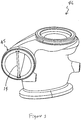
- an exhaust assembly 10 includes an exhaust component 12 and a divider plate 14.
- the exhaust component 12 as shown in Figure 1 is an exhaust manifold, which includes an inlet portion 16, a plurality of runners 18 extending from the inlet portion 16, and an outlet portion 20.
- the inlet portion 16 is connected to an engine block (not shown) and defines a plurality of inlet ports 22.
- the runners 18 define flow channels (not shown) that communicate with the inlet ports 22.
- the outlet portion 20 defines a gas passageway 24. The flow channels of the runners 18 converge into the gas passageway 24.
- the divider plate 14 is provided across the passageway 24 and installed to the outlet portion 20 along a longitudinal direction X of the passageway 24 (i.e., the flow direction of the exhaust gas flow) to divide the passageway 24 into a first chamber 26 and a second chamber 28.
- the exhaust component may be any component in an exhaust system having a passageway to guide and direct exhaust gas flow from an engine.
- the exhaust component may be an exhaust manifold, a turbocharger, an inlet of a turbocharger, or an outlet portion of a combined cylinder head having an integral manifold portion.
- the divider plate 14 is formed from a high temperature capable material with desired mechanical properties at elevated temperatures such as strength, microstructural stability, and/or oxidation resistance, by way of non-limiting examples.
- the divider plate 14 may be formed of a material capable of accommodating significant thermal loads, such as stainless steel and/or ceramics.
- the divider plate 14 may be coated with materials, including but not limited to refractory materials, to enhance these properties.
- the divider plate 14 is resistant to degradation caused by thermal cycling and the like.
- the highest (steady state) material temperatures are generally in the region of the outlet portion 20 of the exhaust component 12.
- the divider plate 14 With the divider plate 14 in the passageway 24, the divider plate 14 can absorb part of heat released from the exhaust gas. Therefore, the exhaust component 12 may be formed from lower grade cast iron materials, by way of non-limiting example.
- the divider plate 14 can be readily installed to the outlet portion 20 in an interference-fit (i.e., press-fit) manner. More specifically, the divider plate 14 is inserted into a groove 30 formed on an inner wall 31 of the outlet portion 20 that defines the gas passageway 24.
- the divider plate 14 may include mechanical features to allow for quick fit in the grooves 30. The mechanical features are designed to allow for an interference fit relationship with the exhaust component, particularly with the groove 30 walls, thereby enabling the divider plate 14 to be locked in the outlet portion 20.
- the divider plate 14 may be specially shaped or be provided with locking tabs, dovetail, or tapering geometry to hold the divider plate 14 in place to prevent rattling or vibration/movement issues such as NVH problems. When the divider plate 14 is locked in the groove 30, the divider plate 14 is prevented from falling out during shipping and assembly.
- the divider plate 14 may be provided with a thin refractory coating to prevent strong adhesion between the cast material of the exhaust component 12 and the divider plate to allow for periodic replacement of the divider plate.
- the divider plate 14 is elastically deformable to absorb loads generated during mounting of the divider plate 14 in the exhaust component 12. As such, minimal loads are transferred to the exhaust component 12 when the divider plate 14 is inserted into the grooves 30, thereby avoiding damage to the groove walls.
- an exhaust component assembly 40 may include an exhaust manifold 41, a divider plate 42 removably inserted in an outlet portion 43 of the exhaust manifold 41, and a cylinder head 44.
- the exhaust manifold 41 is integrally formed with the cylinder head 44.
- the exhaust manifold 41 and the cylinder head 44 may be cast in one casting process.
- the exhaust component is shown to be an inlet portion 45 of a turbocharger 46.
- the divider plate 14 is incorporated in the inlet portion 45 of the turbocharger 46.
- an exhaust component assembly 50 includes an exhaust component 52 and a divider plate 54, this first embodiment being not covered by the claims.
- the exhaust component 52 is shown to be an exhaust manifold. Only an outlet portion 56 of the exhaust manifold is shown for clarity.
- the outlet portion 56 includes inner wall 58 that defines a gas passageway 60.
- a groove 62 is formed on the inner wall 58 and extend along the longitudinal direction X of the gas passageway 60.
- a flange 63 extends radially from the inner wall 58 within the gas passageway 60.
- the flange 63 defines a slot 64 which essentially is a continuation of the groove 62 formed in the inner wall 58.
- the slot 64 and groove 62 define a substantially U-shape receiving space.
- the groove 62 is defined by a pair of opposing groove walls 65 that face one another and an end groove wall 67 that connects the opposing groove walls 65.
- the opposing groove walls 65 define a distance d2.
- the divider plate 54 includes a plurality of wavy surfaces 68 each defining crests 69 and valleys 71.
- the crests 69 on the opposing wavy surfaces 68 define a distance d1 along a thickness direction of the divider plate 54.
- Distance d1 is slightly greater than the distance d2.
- the biasing force of the divider plate 54 pushes the divider plate 54 against the groove walls 65 to lock the divider plate 54 in the groove 62. Therefore, the divider plate 54 and the groove 62, particularly the opposing groove walls 65 are engaged in an interference fit manner.
- the lower portion of the groove 62 otherwise referred to herein as a slot 64 which receives the divider plate 54 is formed to allow for clearance C at least between the bottom edge 73 of the divider plate 54 and the slot 64.
- the clearance C may also be formed between the opposing groove walls 65 and the wavy surfaces 68 of the divider plate 54 adjacent to the slot 64.
- C provide room for thermal expansion of the exhaust component 52 and/or the divider plate 54 when the exhaust component assembly 50 is subjected to high temperature.
- the divider plate 54 may include one wavy surface and one flat surface.
- an exhaust component assembly 80 includes an exhaust component 52 and a divider plate 84.
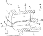
- the divider plate 84 differs from the divider plate 54 of the first embodiment in that the divider plate 84 includes opposing flat surfaces 86 and a plurality of locking tabs 88 extending outwardly and upwardly from the opposing flat surfaces 86. "Upwardly” as used in the context of the locking tabs 88 means “away from the lead-in end of the divider plate 84.
- the locking tabs 88 may be formed by punching the divider plate 84 and bending the locking tabs 88 outwardly.
- the locking tabs 88 are alternately arranged and staggered on the flat surfaces 86 along the longitudinal direction X of the passageway 60.
- locking tabs 88 are shown to be provided on both flat surfaces 86 of the divider plate 84, the locking tabs 88 can be formed on only one flat surface 86.
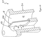
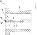
- an exhaust component assembly 90 includes an exhaust component 92 and a divider plate 94.
- the divider plate 94 has a structure similar to that of the divider plate 54 of the second embodiment.
- the exhaust component 92 defines a groove 96 extending along an inner wall 58 that defines the gas passageway 60.
- the groove 96 is defined by an end wall 98 and opposing rugged groove walls 100.
- the opposing rugged groove walls 100 each define protrusions 102 extending toward the groove 96.
- the protrusions which may have varying shapes are shown as wedge-shaped protrusions 102.
- the protrusions 102 are provided to interfere with corresponding locking tabs 88.
- the locking tabs 88 are biased against the rugged groove walls 100.
- the locking tabs 88 may return to their original un-biased or less-biased position and engage the wedge-shaped protrusions 102. As such, the divider plate 94 is securely locked in the grooves 96.
- an exhaust component assembly 110 includes an exhaust component 112 and a divider plate 114. This fourth embodiment is not covered by the claims.
- the exhaust component assembly 110 is similar to that of the first embodiment except for the groove 116.
- the groove 116 has an enlarged portion 118 and a straight portion 120.
- the divider plate 114 engages the straight portion 120 of the groove 116.
- the enlarged portion 118 facilitates insertion of the divider plate 114 into the groove 116.
- any of the grooves 62 and 96 of the first, second and third embodiment can be formed to have the enlarged portion 118 to facilitate insertion of the divider plates 54, 84, 94, 114 into the grooves 62 and 96.
- the exhaust components assemblies according to the present disclosure incorporate divider plates to help absorb heat from the exhaust gas.
- the divider plates have mechanical features to enable the divider plates to be easily installed to the outlet portions of the exhaust manifolds and, depending on the embodiment, may be easily removed for replacement.
Landscapes
- Engineering & Computer Science (AREA)
- Chemical & Material Sciences (AREA)
- Combustion & Propulsion (AREA)
- Mechanical Engineering (AREA)
- General Engineering & Computer Science (AREA)
- Exhaust Silencers (AREA)
- Supercharger (AREA)
Description
- The present disclosure generally relates to exhaust components, such as exhaust manifolds, turbochargers, or catalytic converters, and more particularly to exhaust component assemblies employing press-fit divider plates to protect the exhaust components from thermal damage.
- The background description provided herein is for the purpose of generally presenting the context of the disclosure. Work of the presently named inventors, to the extent that it is described in this background section, as well as aspects of the description that may not otherwise qualify as prior art at the time of filing, are neither expressly nor impliedly admitted as prior art against the present disclosure.
- Exhaust components, such as exhaust manifolds, turbochargers, and catalytic converters are provided downstream from engines to direct and guide exhaust gas flow for further treatment or use and are subject to high temperature. Exhaust manifolds are commonly made from cast iron for high volume production engines. Among the commonly used cast iron material for the exhaust manifolds is silicon-molybdenum cast iron ("SiMo cast iron"). SiMo cast iron becomes weaker as the temperature increases. As a result, the SiMo cast iron is subject to damage from oxidation, decarburization, and coarsening. The duration of time at high temperature determines the amount of material damage that accumulates. The accumulation of damage and the elevated temperature strength (the thermal strength) of the material are important factors in evaluating durability of the exhaust component.
- As automotive companies increase the gas temperatures of their engines to improve efficiency and reduce exhaust emissions, more manifold applications are exceeding the practical working (temperature) limit of cast iron. The temperature distribution in the manifolds is not uniform and some peak temperature areas receive more heat than other areas in the manifolds. SiMo (silicon-molybdenum) cast iron exhaust manifolds have an AC1 temperature of approximately 830-840°C. The AC1 temperature is the temperature at which the ferritic microstructure starts to be converted into austenite. Since a typical maximum gas temperature of the manifold outlet for a current North American gasoline engine is about 900°C, it can be shown that most areas of the manifold will be below the AC1 temperature.
- Currently, if a material such as cast iron is inadequate for the peak temperature, the entire manifold has to be made from a higher grade material (e.g., Ni-Resist, cast steel, or fabricated stainless steel). Therefore, the manufacturing costs for exhaust manifolds for high temperature applications are significantly increased.
- Single material cast exhaust components can suffer severe damage in regions of local high temperature and large thermal gradients such as the outlet or along the bifurcation. The high temperature promotes oxidation and the thermal gradients introduce local strains that may make the oxide layer less adherent. If spalling of the oxide occurs, particles are released into the exhaust gas stream that may bombard and damage downstream components such as turbochargers and catalytic converters.
- The oxidation, particle coarsening, and decarburization that occurs locally in the high temperature regions can significantly degrade the local material properties over time. This may result in premature cracking and warpage, both of which can reduce component durability performance. These effects, in turn, may result in exhaust gases leaking to the environment (through a crack or loss of sealing) or allow exhaust gas to communicate (travel) between separated runners or chambers (either will negatively influence system performance). If large thermally induced strains are co-located with the manifold areas with degraded material properties, component failure by cracking is common.
- Document
EP1734235 A1 discloses an exhaust component assembly which includes an exhaust component and a press-fit divider plate. The exhaust component includes an inner wall defining a gas passageway. The divider plate is inserted into a groove of the gas passageway and secured to the exhaust component. - An exhaust component assembly according to the present disclosure includes an exhaust component and a press-fit divider plate. The exhaust component includes an inner wall defining a gas passageway. The divider plate is inserted into the gas passageway and secured to the exhaust component.
- The present invention relates to an exhaust component assembly according to claim 1.
- An exhaust component assembly includes an inlet portion, and outlet portion, runners connected between the inlet portion and the outlet portion, and at least one divider plate. Depending on the embodiment, at least one of the inlet portions or outlet portions include an inner wall which defines a gas passageway. At least one groove is formed on the inner wall for receiving a divider plate which segregates the gas passageway into at least two distinct chambers.. At least one of the divider plate or groove includes mechanical features for locking the divider plate to groove walls that define the groove.
- Further areas of applicability of the present invention will become apparent from the detailed description provided hereinafter. It should be understood that the detailed description and specific examples, while indicating the preferred embodiment of the invention, are intended for purposes of illustration only and are not intended to limit the scope of the invention.
- The drawings described herein are for illustration purposes only and are not intended to limit the scope of the present disclosure in any way.
-
Figure 1 is a perspective view of an exhaust manifold employing a press-fit divider plate in accordance with the teachings of the present disclosure; -
Figure 2 is a perspective view of an exhaust manifold employing a press-fit divider plate and an engine block integrally formed with the exhaust manifold in accordance with the teachings of the present disclosure; -
Figure 3 is a perspective view of an inlet portion of a turbocharger employing a press-fit divider plate according to the teachings of the present disclosure; -
Figure 4 is a perspective, cross-sectional view of an exhaust component assembly according to a first embodiment of the present disclosure ; this first embodiment is not covered by the claims ; -
Figure 5 is a cross-sectional, exploded view of an exhaust component assembly according to the first embodiment offigure 4 ; -
Figure 6 is a cross-sectional view of an exhaust component assembly according to the first embodiment offigure 4 ; -
Figure 7 is a perspective, cross-sectional view of an exhaust component assembly according to a second embodiment of the present disclosure; -
Figure 8 is a perspective, cross-sectional, exploded view of an exhaust component assembly according to a second embodiment of the present disclosure; -
Figure 9 is a cross-sectional view of an exhaust component assembly according to a second embodiment of the present disclosure; -
Figure 10 is a perspective, cross-sectional view of an exhaust component assembly according to a third embodiment of the present disclosure; -
Figure 11 is a cross-sectional view of an exhaust component assembly according to a third embodiment of the present disclosure; -
Figure 12 is a perspective, cross-sectional, exploded view of an exhaust component assembly according to a third embodiment of the present disclosure; and -
Figure 13 is a perspective, cross-sectional, exploded view of an exhaust component assembly according to a fourth embodiment of the present disclosure ; this fourth embodiment is not covered by the claims. - The following description is merely exemplary in nature and is not intended to limit the present disclosure, application, or uses. It should be understood that throughout the drawings, corresponding reference numerals indicate like or corresponding parts and features.
- Referring to
Figure 1 , anexhaust assembly 10 includes an exhaust component 12 and adivider plate 14. The exhaust component 12 as shown inFigure 1 is an exhaust manifold, which includes aninlet portion 16, a plurality ofrunners 18 extending from theinlet portion 16, and anoutlet portion 20. Theinlet portion 16 is connected to an engine block (not shown) and defines a plurality ofinlet ports 22. Therunners 18 define flow channels (not shown) that communicate with theinlet ports 22. Theoutlet portion 20 defines agas passageway 24. The flow channels of therunners 18 converge into thegas passageway 24. Thedivider plate 14 is provided across thepassageway 24 and installed to theoutlet portion 20 along a longitudinal direction X of the passageway 24 (i.e., the flow direction of the exhaust gas flow) to divide thepassageway 24 into a first chamber 26 and asecond chamber 28. - It is understood and appreciated that while the exhaust component is shown as an exhaust manifold in
Figure 1 , the exhaust component may be any component in an exhaust system having a passageway to guide and direct exhaust gas flow from an engine. For example, the exhaust component may be an exhaust manifold, a turbocharger, an inlet of a turbocharger, or an outlet portion of a combined cylinder head having an integral manifold portion. - The
divider plate 14 is formed from a high temperature capable material with desired mechanical properties at elevated temperatures such as strength, microstructural stability, and/or oxidation resistance, by way of non-limiting examples. For example, thedivider plate 14 may be formed of a material capable of accommodating significant thermal loads, such as stainless steel and/or ceramics. Thedivider plate 14 may be coated with materials, including but not limited to refractory materials, to enhance these properties. Thedivider plate 14 is resistant to degradation caused by thermal cycling and the like. - The highest (steady state) material temperatures are generally in the region of the
outlet portion 20 of the exhaust component 12. With thedivider plate 14 in thepassageway 24, thedivider plate 14 can absorb part of heat released from the exhaust gas. Therefore, the exhaust component 12 may be formed from lower grade cast iron materials, by way of non-limiting example. - The
divider plate 14 can be readily installed to theoutlet portion 20 in an interference-fit (i.e., press-fit) manner. More specifically, thedivider plate 14 is inserted into agroove 30 formed on an inner wall 31 of theoutlet portion 20 that defines thegas passageway 24. Thedivider plate 14 may include mechanical features to allow for quick fit in thegrooves 30. The mechanical features are designed to allow for an interference fit relationship with the exhaust component, particularly with thegroove 30 walls, thereby enabling thedivider plate 14 to be locked in theoutlet portion 20. - For example, the
divider plate 14 may be specially shaped or be provided with locking tabs, dovetail, or tapering geometry to hold thedivider plate 14 in place to prevent rattling or vibration/movement issues such as NVH problems. When thedivider plate 14 is locked in thegroove 30, thedivider plate 14 is prevented from falling out during shipping and assembly. Optionally, thedivider plate 14 may be provided with a thin refractory coating to prevent strong adhesion between the cast material of the exhaust component 12 and the divider plate to allow for periodic replacement of the divider plate. - The
divider plate 14 is elastically deformable to absorb loads generated during mounting of thedivider plate 14 in the exhaust component 12. As such, minimal loads are transferred to the exhaust component 12 when thedivider plate 14 is inserted into thegrooves 30, thereby avoiding damage to the groove walls. - Referring to
Figure 2 , anexhaust component assembly 40 may include an exhaust manifold 41, adivider plate 42 removably inserted in anoutlet portion 43 of the exhaust manifold 41, and acylinder head 44. The exhaust manifold 41 is integrally formed with thecylinder head 44. For example, the exhaust manifold 41 and thecylinder head 44 may be cast in one casting process. - Referring to
Figure 3 , the exhaust component is shown to be aninlet portion 45 of aturbocharger 46. Thedivider plate 14 is incorporated in theinlet portion 45 of theturbocharger 46. - Referring to
Figures 4 to 6 , an exhaust component assembly 50 according to a first embodiment of the present disclosure includes anexhaust component 52 and adivider plate 54, this first embodiment being not covered by the claims. Theexhaust component 52 is shown to be an exhaust manifold. Only anoutlet portion 56 of the exhaust manifold is shown for clarity. Theoutlet portion 56 includesinner wall 58 that defines agas passageway 60. Agroove 62 is formed on theinner wall 58 and extend along the longitudinal direction X of thegas passageway 60. Aflange 63 extends radially from theinner wall 58 within thegas passageway 60. Theflange 63 defines aslot 64 which essentially is a continuation of thegroove 62 formed in theinner wall 58. Theslot 64 andgroove 62 define a substantially U-shape receiving space. - The
groove 62 is defined by a pair of opposinggroove walls 65 that face one another and anend groove wall 67 that connects the opposinggroove walls 65. The opposinggroove walls 65 define a distance d2. Thedivider plate 54 includes a plurality ofwavy surfaces 68 each defining crests 69 andvalleys 71. The crests 69 on the opposingwavy surfaces 68 define a distance d1 along a thickness direction of thedivider plate 54. Distance d1 is slightly greater than the distance d2. When thedivider plate 54 is inserted into thegrooves 62, thewavy surfaces 68, particularly, thecrests 69 on thewavy surfaces 68 are biased against the opposinggroove walls 65. When thedivider plate 54 is positioned in place, the biasing force of thedivider plate 54 pushes thedivider plate 54 against thegroove walls 65 to lock thedivider plate 54 in thegroove 62. Therefore, thedivider plate 54 and thegroove 62, particularly the opposinggroove walls 65 are engaged in an interference fit manner. - The lower portion of the
groove 62 otherwise referred to herein as aslot 64 which receives thedivider plate 54 is formed to allow for clearance C at least between thebottom edge 73 of thedivider plate 54 and theslot 64. The clearance C may also be formed between the opposinggroove walls 65 and thewavy surfaces 68 of thedivider plate 54 adjacent to theslot 64. The clearances - C provide room for thermal expansion of the
exhaust component 52 and/or thedivider plate 54 when the exhaust component assembly 50 is subjected to high temperature. - While not shown in the drawings, it is understood and appreciated that the
divider plate 54 may include one wavy surface and one flat surface. - Referring to
Figures 7 to 9 , anexhaust component assembly 80 according to a second embodiment of the present disclosure includes anexhaust component 52 and adivider plate 84. In the following, like components in different embodiments are indicated by like reference numerals. Thedivider plate 84 differs from thedivider plate 54 of the first embodiment in that thedivider plate 84 includes opposingflat surfaces 86 and a plurality of lockingtabs 88 extending outwardly and upwardly from the opposing flat surfaces 86. "Upwardly" as used in the context of the lockingtabs 88 means "away from the lead-in end of thedivider plate 84. When thedivider plate 84 is inserted into thegroove 62, the lockingtabs 88 are biased against the opposinggroove walls 65. When thedivider plate 84 is inserted in place, the biasing force of the lockingtabs 88 locks thedivider plate 84 in thegroove 62 to achieve an interference fit. The lockingtabs 88 may be formed by punching thedivider plate 84 and bending the lockingtabs 88 outwardly. The lockingtabs 88 are alternately arranged and staggered on theflat surfaces 86 along the longitudinal direction X of thepassageway 60. - It is understood and appreciated that while locking
tabs 88 are shown to be provided on bothflat surfaces 86 of thedivider plate 84, the lockingtabs 88 can be formed on only oneflat surface 86. - Referring to
Figures 10 to 12 , an exhaust component assembly 90 according to a third embodiment of the present disclosure includes anexhaust component 92 and adivider plate 94. Thedivider plate 94 has a structure similar to that of thedivider plate 54 of the second embodiment. Theexhaust component 92 defines agroove 96 extending along aninner wall 58 that defines thegas passageway 60. Thegroove 96 is defined by anend wall 98 and opposingrugged groove walls 100. The opposingrugged groove walls 100 each defineprotrusions 102 extending toward thegroove 96. The protrusions which may have varying shapes are shown as wedge-shapedprotrusions 102. Theprotrusions 102 are provided to interfere with corresponding lockingtabs 88. When thedivider plate 94 is inserted in thegroove 96, the lockingtabs 88 are biased against therugged groove walls 100. When thedivider plate 94 is in place, the lockingtabs 88 may return to their original un-biased or less-biased position and engage the wedge-shapedprotrusions 102. As such, thedivider plate 94 is securely locked in thegrooves 96. - Referring to
Figure 13 , an exhaust component assembly 110 according to a fourth embodiment of the present disclosure includes an exhaust component 112 and a divider plate 114. This fourth embodiment is not covered by the claims. The exhaust component assembly 110 is similar to that of the first embodiment except for the groove 116. The groove 116 has anenlarged portion 118 and astraight portion 120. The divider plate 114 engages thestraight portion 120 of the groove 116. Theenlarged portion 118 facilitates insertion of the divider plate 114 into the groove 116. - While not shown in the drawings, it is understood and appreciated that any of the
grooves enlarged portion 118 to facilitate insertion of thedivider plates grooves - The exhaust components assemblies according to the present disclosure incorporate divider plates to help absorb heat from the exhaust gas. The divider plates have mechanical features to enable the divider plates to be easily installed to the outlet portions of the exhaust manifolds and, depending on the embodiment, may be easily removed for replacement.
- While the examples and discussion of the present disclosure generally relate to exhaust manifold outlet applications, it should be understood by those skilled in the art that the general concepts discussed herein are also applicable to other "exhaust components" such as turbocharger inlets. Additionally, while each of the embodiments depicted pertain to cast manifold applications, it should also be recognized that the divider plate may be used in fabricated exhaust systems.
- Those skilled in the art can now appreciate from the foregoing description that the broad teachings of the present disclosure can be implemented in a variety of forms. Therefore, while this disclosure has been described in connection with particular examples thereof, the scope of the invention as defined in the claims should not be so limited since other modifications will become apparent to the skilled practitioner upon a study of the drawings, the specification and the following claims.
Claims (8)
- An exhaust component assembly (10, 80, 90) comprising:an exhaust component (52, 92) that includes an inner wall (58) having at least one recessed groove (62, 96); anda divider plate (84, 94) inserted into the groove (62, 96) and secured to the exhaust component, the divider plate (84, 94) including first and second faces (86) and an edge extending between the first and second faces, the first face (86) cooperating with the inner wall (58) to define a first gas passageway (26), the second face (86) cooperating with the inner wall (58) to define a second gas passageway (28),characterized by at least one of the first and second faces (86) includes locking tabs (88) extending therefrom and engaging the at least one recessed groove (62, 96) for locking the divider plate (84, 94) in the at least one recessed groove (62, 96).
- The exhaust component assembly of Claim 1, wherein the divider plate (84, 94) is secured to the exhaust component (52, 92) by an interference fit between said divider plate and the exhaust component.
- The exhaust component assembly of Claim 1, wherein the locking tabs (88) engage at least one rugged groove wall (100) that defines the at least one groove (96).
- The exhaust component assembly of Claim 3, wherein the at least one rugged groove wall (100) defines protrusions (102) for interfering with the locking tabs (88).
- The exhaust component assembly of Claim 4, wherein the protrusions (102) are substantially wedge shaped.
- The exhaust component assembly of Claim 1, wherein the locking tabs (88) extend from the first face (86) and from the second face (86) of the divider plate (84, 94).
- The exhaust component assembly of Claim 1, wherein the at least one groove (62, 96) includes an enlarged portion (118) at a lead-in end.
- The exhaust component assembly of Claim 1, further comprising
an inlet portion (16);
an outlet portion (20) defining an inner wall (31), a gas passageway (24) defined by the inner wall, and at least one groove (62, 96) formed on the inner wall; and
a plurality of runners (18) converging at said first and second gas passageways (26, 28).
Applications Claiming Priority (2)
| Application Number | Priority Date | Filing Date | Title |
|---|---|---|---|
| US12/509,999 US8371115B2 (en) | 2005-06-13 | 2009-07-27 | Exhaust component assemblies with divider plates |
| PCT/IB2010/001861 WO2011012983A1 (en) | 2009-07-27 | 2010-07-27 | Exhaust component assemblies with divider plates |
Publications (3)
| Publication Number | Publication Date |
|---|---|
| EP2459856A1 EP2459856A1 (en) | 2012-06-06 |
| EP2459856A4 EP2459856A4 (en) | 2014-05-14 |
| EP2459856B1 true EP2459856B1 (en) | 2016-12-28 |
Family
ID=43528825
Family Applications (1)
| Application Number | Title | Priority Date | Filing Date |
|---|---|---|---|
| EP10803968.6A Not-in-force EP2459856B1 (en) | 2009-07-27 | 2010-07-27 | Exhaust component assemblies with divider plates |
Country Status (5)
| Country | Link |
|---|---|
| US (1) | US8371115B2 (en) |
| EP (1) | EP2459856B1 (en) |
| CN (1) | CN102575558A (en) |
| CA (1) | CA2769579C (en) |
| WO (1) | WO2011012983A1 (en) |
Families Citing this family (11)
| Publication number | Priority date | Publication date | Assignee | Title |
|---|---|---|---|---|
| CN101858241B (en) * | 2009-04-03 | 2014-05-14 | 本田技研工业株式会社 | Seperate exhaust component |
| DE102009048407B4 (en) * | 2009-10-06 | 2012-11-15 | Tenneco Gmbh | exhaust system |
| US8999229B2 (en) | 2010-11-17 | 2015-04-07 | Alpha Sintered Metals, Inc. | Components for exhaust system, methods of manufacture thereof and articles comprising the same |
| US8763018B2 (en) * | 2011-08-22 | 2014-06-24 | Solarflare Communications, Inc. | Modifying application behaviour |
| KR101956731B1 (en) * | 2012-08-10 | 2019-03-12 | 테네코 오토모티브 오퍼레이팅 컴파니 인코포레이티드 | Method for mixing an exhaust gas flow |
| DE102013211390B4 (en) * | 2013-06-18 | 2015-08-06 | Eberspächer Exhaust Technology GmbH & Co. KG | Air gap insulated exhaust manifold and thus equipped supercharged internal combustion engine |
| US9163548B2 (en) | 2013-10-02 | 2015-10-20 | Ford Global Technologies, Llc | Exhaust system including an exhaust manifold having an integrated mixer plate |
| US20150322898A1 (en) * | 2014-05-07 | 2015-11-12 | Caterpillar Inc. | Heat exchanger for exhaust gas recirculation unit |
| US9774706B2 (en) * | 2014-09-30 | 2017-09-26 | Level 3 Communications, Llc | Providing functional requirements for a network connection from a local library |
| CN106555659B (en) * | 2015-09-29 | 2019-07-09 | 长城汽车股份有限公司 | Double outlet Decorative Covers and automobile |
| US10801380B1 (en) * | 2017-11-29 | 2020-10-13 | Steve Sousley | Durable high performance water-cooled exhaust systems and components and methods of manufacture |
Family Cites Families (16)
| Publication number | Priority date | Publication date | Assignee | Title |
|---|---|---|---|---|
| US3768260A (en) * | 1971-08-13 | 1973-10-30 | Westinghouse Electric Corp | Manifold thermal reactor |
| US4084658A (en) * | 1976-11-05 | 1978-04-18 | Custom-Bilt | Tunable expansion chamber for internal combustion engines |
| US4796426A (en) * | 1982-07-06 | 1989-01-10 | Feuling James J | High efficiency transition element positioned intermediate multi-cylinder exhaust system and secondary pipe assemblies |
| GB8429212D0 (en) * | 1984-11-19 | 1984-12-27 | Vincent Patents Ltd | Exhaust systems for ic engines |
| US4790134A (en) * | 1987-06-11 | 1988-12-13 | Brunswick Corporation | Outboard motor exhaust tube divider |
| US5148675A (en) * | 1991-04-26 | 1992-09-22 | Inman Frederick R | Marine exhaust manifold and header pipe system |
| US5284016A (en) * | 1992-08-28 | 1994-02-08 | General Motors Corporation | Exhaust gas burner reactor |
| US5473891A (en) | 1994-06-10 | 1995-12-12 | Ap Parts Manufacturing Company | Three-piece stamp formed connector for achieving equal length exhaust pipes |
| JP3497809B2 (en) * | 2000-10-10 | 2004-02-16 | 本田技研工業株式会社 | Exhaust system partition structure |
| JP2004003444A (en) * | 2002-03-27 | 2004-01-08 | Yumex Corp | Exhaust manifold assembly structure |
| AU2003289117A1 (en) * | 2002-12-24 | 2004-07-22 | Yumex Corporation | Exhaust manifold |
| JP2005163623A (en) * | 2003-12-02 | 2005-06-23 | Calsonic Kansei Corp | Exhaust manifold |
| FR2875266B1 (en) | 2004-09-14 | 2006-12-08 | Renault Sas | EXHAUST MANIFOLD FOR INTERNAL COMBUSTION ENGINE |
| US7028663B1 (en) * | 2005-01-26 | 2006-04-18 | Kim Jay S | Fluid swirling device |
| US7565800B2 (en) | 2005-06-13 | 2009-07-28 | Wescast Industries, Inc. | Exhaust components including high temperature divider plate assemblies |
| JP4760287B2 (en) * | 2005-10-13 | 2011-08-31 | 日産自動車株式会社 | Exhaust device for internal combustion engine |
-
2009
- 2009-07-27 US US12/509,999 patent/US8371115B2/en not_active Expired - Fee Related
-
2010
- 2010-07-27 EP EP10803968.6A patent/EP2459856B1/en not_active Not-in-force
- 2010-07-27 WO PCT/IB2010/001861 patent/WO2011012983A1/en not_active Ceased
- 2010-07-27 CA CA2769579A patent/CA2769579C/en not_active Expired - Fee Related
- 2010-07-27 CN CN2010800430974A patent/CN102575558A/en active Pending
Non-Patent Citations (1)
| Title |
|---|
| None * |
Also Published As
| Publication number | Publication date |
|---|---|
| EP2459856A1 (en) | 2012-06-06 |
| WO2011012983A1 (en) | 2011-02-03 |
| CA2769579C (en) | 2016-02-09 |
| US8371115B2 (en) | 2013-02-12 |
| CA2769579A1 (en) | 2011-02-03 |
| US20100005793A1 (en) | 2010-01-14 |
| CN102575558A (en) | 2012-07-11 |
| EP2459856A4 (en) | 2014-05-14 |
Similar Documents
| Publication | Publication Date | Title |
|---|---|---|
| CA2769579C (en) | Exhaust component assemblies with divider plates | |
| US7565800B2 (en) | Exhaust components including high temperature divider plate assemblies | |
| EP0437302B1 (en) | Ceramic port liners | |
| EP2514925B1 (en) | Ceramix matirx composite shroud attachement system | |
| EP2562448B1 (en) | Oil ring for internal combustion engine | |
| US6220605B1 (en) | Slip joint connection for engine exhaust system | |
| CN102159392B (en) | Compressible ceramic seal | |
| US20130011248A1 (en) | Reduction in thermal stresses in monolithic ceramic or ceramic matrix composite shroud | |
| US10113505B2 (en) | Gasket and engine with the gasket | |
| CN114761679B (en) | Slotted injector nozzle combustion shroud | |
| CN108884938B (en) | Gasket for internal combustion engine | |
| GB2247729A (en) | Mounting assembly. | |
| US6959543B2 (en) | Exhaust gas manifold of an exhaust system for an internal combustion engine | |
| US20080309022A1 (en) | Two-Part Oil Scraper Ring for Internal Combustion Engines | |
| CN115298485A (en) | Combustion chamber with ceramic heat shield and seal | |
| EP4343178A1 (en) | Gasket | |
| Prasse et al. | A critical analysis of the rotary engine sealing problem | |
| KR101162386B1 (en) | Exhaust manifold gasket | |
| US20100164182A1 (en) | Multi-part oil scraper ring for internal combustion engines | |
| CN117889688A (en) | Heat exchanger | |
| MAHLE GmbH | Piston rings | |
| CN101023259B (en) | Exhaust manifold gasket | |
| JP2020204310A (en) | Holding structure for addition valve | |
| JP2014095345A (en) | Internal combustion engine | |
| CN116097038A (en) | Seal for use in a heat shield element |
Legal Events
| Date | Code | Title | Description |
|---|---|---|---|
| PUAI | Public reference made under article 153(3) epc to a published international application that has entered the european phase |
Free format text: ORIGINAL CODE: 0009012 |
|
| 17P | Request for examination filed |
Effective date: 20120127 |
|
| AK | Designated contracting states |
Kind code of ref document: A1 Designated state(s): AL AT BE BG CH CY CZ DE DK EE ES FI FR GB GR HR HU IE IS IT LI LT LU LV MC MK MT NL NO PL PT RO SE SI SK SM TR |
|
| DAX | Request for extension of the european patent (deleted) | ||
| A4 | Supplementary search report drawn up and despatched |
Effective date: 20140415 |
|
| RIC1 | Information provided on ipc code assigned before grant |
Ipc: F01N 13/10 20100101ALI20140409BHEP Ipc: F02B 67/10 20060101ALI20140409BHEP Ipc: F01N 13/18 20100101ALI20140409BHEP Ipc: F01N 13/08 20100101AFI20140409BHEP |
|
| 17Q | First examination report despatched |
Effective date: 20160121 |
|
| GRAP | Despatch of communication of intention to grant a patent |
Free format text: ORIGINAL CODE: EPIDOSNIGR1 |
|
| INTG | Intention to grant announced |
Effective date: 20160922 |
|
| STAA | Information on the status of an ep patent application or granted ep patent |
Free format text: STATUS: GRANT OF PATENT IS INTENDED |
|
| GRAS | Grant fee paid |
Free format text: ORIGINAL CODE: EPIDOSNIGR3 |
|
| GRAA | (expected) grant |
Free format text: ORIGINAL CODE: 0009210 |
|
| STAA | Information on the status of an ep patent application or granted ep patent |
Free format text: STATUS: THE PATENT HAS BEEN GRANTED |
|
| AK | Designated contracting states |
Kind code of ref document: B1 Designated state(s): AL AT BE BG CH CY CZ DE DK EE ES FI FR GB GR HR HU IE IS IT LI LT LU LV MC MK MT NL NO PL PT RO SE SI SK SM TR |
|
| REG | Reference to a national code |
Ref country code: GB Ref legal event code: FG4D |
|
| REG | Reference to a national code |
Ref country code: CH Ref legal event code: EP |
|
| REG | Reference to a national code |
Ref country code: AT Ref legal event code: REF Ref document number: 857500 Country of ref document: AT Kind code of ref document: T Effective date: 20170115 |
|
| REG | Reference to a national code |
Ref country code: IE Ref legal event code: FG4D |
|
| REG | Reference to a national code |
Ref country code: DE Ref legal event code: R096 Ref document number: 602010039206 Country of ref document: DE |
|
| PG25 | Lapsed in a contracting state [announced via postgrant information from national office to epo] |
Ref country code: LV Free format text: LAPSE BECAUSE OF FAILURE TO SUBMIT A TRANSLATION OF THE DESCRIPTION OR TO PAY THE FEE WITHIN THE PRESCRIBED TIME-LIMIT Effective date: 20161228 |
|
| REG | Reference to a national code |
Ref country code: LT Ref legal event code: MG4D |
|
| PG25 | Lapsed in a contracting state [announced via postgrant information from national office to epo] |
Ref country code: LT Free format text: LAPSE BECAUSE OF FAILURE TO SUBMIT A TRANSLATION OF THE DESCRIPTION OR TO PAY THE FEE WITHIN THE PRESCRIBED TIME-LIMIT Effective date: 20161228 Ref country code: NO Free format text: LAPSE BECAUSE OF FAILURE TO SUBMIT A TRANSLATION OF THE DESCRIPTION OR TO PAY THE FEE WITHIN THE PRESCRIBED TIME-LIMIT Effective date: 20170328 Ref country code: SE Free format text: LAPSE BECAUSE OF FAILURE TO SUBMIT A TRANSLATION OF THE DESCRIPTION OR TO PAY THE FEE WITHIN THE PRESCRIBED TIME-LIMIT Effective date: 20161228 Ref country code: GR Free format text: LAPSE BECAUSE OF FAILURE TO SUBMIT A TRANSLATION OF THE DESCRIPTION OR TO PAY THE FEE WITHIN THE PRESCRIBED TIME-LIMIT Effective date: 20170329 |
|
| REG | Reference to a national code |
Ref country code: NL Ref legal event code: MP Effective date: 20161228 |
|
| REG | Reference to a national code |
Ref country code: AT Ref legal event code: MK05 Ref document number: 857500 Country of ref document: AT Kind code of ref document: T Effective date: 20161228 |
|
| PG25 | Lapsed in a contracting state [announced via postgrant information from national office to epo] |
Ref country code: HR Free format text: LAPSE BECAUSE OF FAILURE TO SUBMIT A TRANSLATION OF THE DESCRIPTION OR TO PAY THE FEE WITHIN THE PRESCRIBED TIME-LIMIT Effective date: 20161228 Ref country code: FI Free format text: LAPSE BECAUSE OF FAILURE TO SUBMIT A TRANSLATION OF THE DESCRIPTION OR TO PAY THE FEE WITHIN THE PRESCRIBED TIME-LIMIT Effective date: 20161228 |
|
| PG25 | Lapsed in a contracting state [announced via postgrant information from national office to epo] |
Ref country code: NL Free format text: LAPSE BECAUSE OF FAILURE TO SUBMIT A TRANSLATION OF THE DESCRIPTION OR TO PAY THE FEE WITHIN THE PRESCRIBED TIME-LIMIT Effective date: 20161228 |
|
| REG | Reference to a national code |
Ref country code: FR Ref legal event code: PLFP Year of fee payment: 8 |
|
| PG25 | Lapsed in a contracting state [announced via postgrant information from national office to epo] |
Ref country code: SK Free format text: LAPSE BECAUSE OF FAILURE TO SUBMIT A TRANSLATION OF THE DESCRIPTION OR TO PAY THE FEE WITHIN THE PRESCRIBED TIME-LIMIT Effective date: 20161228 Ref country code: CZ Free format text: LAPSE BECAUSE OF FAILURE TO SUBMIT A TRANSLATION OF THE DESCRIPTION OR TO PAY THE FEE WITHIN THE PRESCRIBED TIME-LIMIT Effective date: 20161228 Ref country code: RO Free format text: LAPSE BECAUSE OF FAILURE TO SUBMIT A TRANSLATION OF THE DESCRIPTION OR TO PAY THE FEE WITHIN THE PRESCRIBED TIME-LIMIT Effective date: 20161228 Ref country code: EE Free format text: LAPSE BECAUSE OF FAILURE TO SUBMIT A TRANSLATION OF THE DESCRIPTION OR TO PAY THE FEE WITHIN THE PRESCRIBED TIME-LIMIT Effective date: 20161228 Ref country code: IS Free format text: LAPSE BECAUSE OF FAILURE TO SUBMIT A TRANSLATION OF THE DESCRIPTION OR TO PAY THE FEE WITHIN THE PRESCRIBED TIME-LIMIT Effective date: 20170428 |
|
| PG25 | Lapsed in a contracting state [announced via postgrant information from national office to epo] |
Ref country code: AT Free format text: LAPSE BECAUSE OF FAILURE TO SUBMIT A TRANSLATION OF THE DESCRIPTION OR TO PAY THE FEE WITHIN THE PRESCRIBED TIME-LIMIT Effective date: 20161228 Ref country code: IT Free format text: LAPSE BECAUSE OF FAILURE TO SUBMIT A TRANSLATION OF THE DESCRIPTION OR TO PAY THE FEE WITHIN THE PRESCRIBED TIME-LIMIT Effective date: 20161228 Ref country code: ES Free format text: LAPSE BECAUSE OF FAILURE TO SUBMIT A TRANSLATION OF THE DESCRIPTION OR TO PAY THE FEE WITHIN THE PRESCRIBED TIME-LIMIT Effective date: 20161228 Ref country code: PL Free format text: LAPSE BECAUSE OF FAILURE TO SUBMIT A TRANSLATION OF THE DESCRIPTION OR TO PAY THE FEE WITHIN THE PRESCRIBED TIME-LIMIT Effective date: 20161228 Ref country code: BE Free format text: LAPSE BECAUSE OF FAILURE TO SUBMIT A TRANSLATION OF THE DESCRIPTION OR TO PAY THE FEE WITHIN THE PRESCRIBED TIME-LIMIT Effective date: 20161228 Ref country code: SM Free format text: LAPSE BECAUSE OF FAILURE TO SUBMIT A TRANSLATION OF THE DESCRIPTION OR TO PAY THE FEE WITHIN THE PRESCRIBED TIME-LIMIT Effective date: 20161228 Ref country code: PT Free format text: LAPSE BECAUSE OF FAILURE TO SUBMIT A TRANSLATION OF THE DESCRIPTION OR TO PAY THE FEE WITHIN THE PRESCRIBED TIME-LIMIT Effective date: 20170428 Ref country code: BG Free format text: LAPSE BECAUSE OF FAILURE TO SUBMIT A TRANSLATION OF THE DESCRIPTION OR TO PAY THE FEE WITHIN THE PRESCRIBED TIME-LIMIT Effective date: 20170328 |
|
| REG | Reference to a national code |
Ref country code: DE Ref legal event code: R097 Ref document number: 602010039206 Country of ref document: DE |
|
| PGFP | Annual fee paid to national office [announced via postgrant information from national office to epo] |
Ref country code: FR Payment date: 20170726 Year of fee payment: 8 Ref country code: DE Payment date: 20170727 Year of fee payment: 8 |
|
| PLBE | No opposition filed within time limit |
Free format text: ORIGINAL CODE: 0009261 |
|
| STAA | Information on the status of an ep patent application or granted ep patent |
Free format text: STATUS: NO OPPOSITION FILED WITHIN TIME LIMIT |
|
| PG25 | Lapsed in a contracting state [announced via postgrant information from national office to epo] |
Ref country code: DK Free format text: LAPSE BECAUSE OF FAILURE TO SUBMIT A TRANSLATION OF THE DESCRIPTION OR TO PAY THE FEE WITHIN THE PRESCRIBED TIME-LIMIT Effective date: 20161228 |
|
| 26N | No opposition filed |
Effective date: 20170929 |
|
| PG25 | Lapsed in a contracting state [announced via postgrant information from national office to epo] |
Ref country code: SI Free format text: LAPSE BECAUSE OF FAILURE TO SUBMIT A TRANSLATION OF THE DESCRIPTION OR TO PAY THE FEE WITHIN THE PRESCRIBED TIME-LIMIT Effective date: 20161228 |
|
| REG | Reference to a national code |
Ref country code: CH Ref legal event code: PL |
|
| GBPC | Gb: european patent ceased through non-payment of renewal fee |
Effective date: 20170727 |
|
| REG | Reference to a national code |
Ref country code: IE Ref legal event code: MM4A |
|
| PG25 | Lapsed in a contracting state [announced via postgrant information from national office to epo] |
Ref country code: CH Free format text: LAPSE BECAUSE OF NON-PAYMENT OF DUE FEES Effective date: 20170731 Ref country code: GB Free format text: LAPSE BECAUSE OF NON-PAYMENT OF DUE FEES Effective date: 20170727 Ref country code: LI Free format text: LAPSE BECAUSE OF NON-PAYMENT OF DUE FEES Effective date: 20170731 Ref country code: IE Free format text: LAPSE BECAUSE OF NON-PAYMENT OF DUE FEES Effective date: 20170727 |
|
| PG25 | Lapsed in a contracting state [announced via postgrant information from national office to epo] |
Ref country code: LU Free format text: LAPSE BECAUSE OF NON-PAYMENT OF DUE FEES Effective date: 20170727 |
|
| PG25 | Lapsed in a contracting state [announced via postgrant information from national office to epo] |
Ref country code: MT Free format text: LAPSE BECAUSE OF NON-PAYMENT OF DUE FEES Effective date: 20170727 |
|
| REG | Reference to a national code |
Ref country code: DE Ref legal event code: R119 Ref document number: 602010039206 Country of ref document: DE |
|
| PG25 | Lapsed in a contracting state [announced via postgrant information from national office to epo] |
Ref country code: DE Free format text: LAPSE BECAUSE OF NON-PAYMENT OF DUE FEES Effective date: 20190201 Ref country code: FR Free format text: LAPSE BECAUSE OF NON-PAYMENT OF DUE FEES Effective date: 20180731 |
|
| PG25 | Lapsed in a contracting state [announced via postgrant information from national office to epo] |
Ref country code: HU Free format text: LAPSE BECAUSE OF FAILURE TO SUBMIT A TRANSLATION OF THE DESCRIPTION OR TO PAY THE FEE WITHIN THE PRESCRIBED TIME-LIMIT; INVALID AB INITIO Effective date: 20100727 Ref country code: MC Free format text: LAPSE BECAUSE OF FAILURE TO SUBMIT A TRANSLATION OF THE DESCRIPTION OR TO PAY THE FEE WITHIN THE PRESCRIBED TIME-LIMIT Effective date: 20161228 |
|
| PG25 | Lapsed in a contracting state [announced via postgrant information from national office to epo] |
Ref country code: CY Free format text: LAPSE BECAUSE OF NON-PAYMENT OF DUE FEES Effective date: 20161228 |
|
| PG25 | Lapsed in a contracting state [announced via postgrant information from national office to epo] |
Ref country code: MK Free format text: LAPSE BECAUSE OF FAILURE TO SUBMIT A TRANSLATION OF THE DESCRIPTION OR TO PAY THE FEE WITHIN THE PRESCRIBED TIME-LIMIT Effective date: 20161228 |
|
| PG25 | Lapsed in a contracting state [announced via postgrant information from national office to epo] |
Ref country code: TR Free format text: LAPSE BECAUSE OF FAILURE TO SUBMIT A TRANSLATION OF THE DESCRIPTION OR TO PAY THE FEE WITHIN THE PRESCRIBED TIME-LIMIT Effective date: 20161228 |
|
| PG25 | Lapsed in a contracting state [announced via postgrant information from national office to epo] |
Ref country code: AL Free format text: LAPSE BECAUSE OF FAILURE TO SUBMIT A TRANSLATION OF THE DESCRIPTION OR TO PAY THE FEE WITHIN THE PRESCRIBED TIME-LIMIT Effective date: 20161228 |