EP2459798B1 - Heater pocket for a household appliance - Google Patents
Heater pocket for a household appliance Download PDFInfo
- Publication number
- EP2459798B1 EP2459798B1 EP10737882.0A EP10737882A EP2459798B1 EP 2459798 B1 EP2459798 B1 EP 2459798B1 EP 10737882 A EP10737882 A EP 10737882A EP 2459798 B1 EP2459798 B1 EP 2459798B1
- Authority
- EP
- European Patent Office
- Prior art keywords
- sidewall
- heater
- bottom wall
- washing liquid
- household appliance
- Prior art date
- Legal status (The legal status is an assumption and is not a legal conclusion. Google has not performed a legal analysis and makes no representation as to the accuracy of the status listed.)
- Not-in-force
Links
- 238000005406 washing Methods 0.000 claims description 106
- 239000007788 liquid Substances 0.000 claims description 85
- 238000010438 heat treatment Methods 0.000 claims description 52
- 239000012530 fluid Substances 0.000 claims description 16
- 238000004891 communication Methods 0.000 claims description 9
- 238000004140 cleaning Methods 0.000 claims description 6
- 230000000994 depressogenic effect Effects 0.000 claims description 2
- 238000009826 distribution Methods 0.000 description 9
- 230000001965 increasing effect Effects 0.000 description 8
- 230000001788 irregular Effects 0.000 description 8
- XLYOFNOQVPJJNP-UHFFFAOYSA-N water Substances O XLYOFNOQVPJJNP-UHFFFAOYSA-N 0.000 description 6
- 238000009825 accumulation Methods 0.000 description 5
- 238000009987 spinning Methods 0.000 description 5
- 235000008733 Citrus aurantifolia Nutrition 0.000 description 4
- 235000011941 Tilia x europaea Nutrition 0.000 description 4
- 239000004571 lime Substances 0.000 description 4
- 239000002245 particle Substances 0.000 description 4
- 238000007792 addition Methods 0.000 description 2
- 230000015572 biosynthetic process Effects 0.000 description 2
- 239000000356 contaminant Substances 0.000 description 2
- 230000008021 deposition Effects 0.000 description 2
- 238000007599 discharging Methods 0.000 description 2
- 238000005755 formation reaction Methods 0.000 description 2
- 230000000717 retained effect Effects 0.000 description 2
- 238000010408 sweeping Methods 0.000 description 2
- 238000012546 transfer Methods 0.000 description 2
- 239000011248 coating agent Substances 0.000 description 1
- 238000000576 coating method Methods 0.000 description 1
- 238000010276 construction Methods 0.000 description 1
- 238000013461 design Methods 0.000 description 1
- 230000000694 effects Effects 0.000 description 1
- 230000001939 inductive effect Effects 0.000 description 1
- 238000009413 insulation Methods 0.000 description 1
- 238000004519 manufacturing process Methods 0.000 description 1
- 239000000463 material Substances 0.000 description 1
- 239000002184 metal Substances 0.000 description 1
- 238000012986 modification Methods 0.000 description 1
- 230000004048 modification Effects 0.000 description 1
- 230000010355 oscillation Effects 0.000 description 1
- 238000013021 overheating Methods 0.000 description 1
- 230000001737 promoting effect Effects 0.000 description 1
- 238000012552 review Methods 0.000 description 1
- 238000009827 uniform distribution Methods 0.000 description 1
Images


Classifications
-
- D—TEXTILES; PAPER
- D06—TREATMENT OF TEXTILES OR THE LIKE; LAUNDERING; FLEXIBLE MATERIALS NOT OTHERWISE PROVIDED FOR
- D06F—LAUNDERING, DRYING, IRONING, PRESSING OR FOLDING TEXTILE ARTICLES
- D06F37/00—Details specific to washing machines covered by groups D06F21/00 - D06F25/00
- D06F37/26—Casings; Tubs
- D06F37/265—Counterweights mounted to the tub; Mountings therefor
-
- D—TEXTILES; PAPER
- D06—TREATMENT OF TEXTILES OR THE LIKE; LAUNDERING; FLEXIBLE MATERIALS NOT OTHERWISE PROVIDED FOR
- D06F—LAUNDERING, DRYING, IRONING, PRESSING OR FOLDING TEXTILE ARTICLES
- D06F39/00—Details of washing machines not specific to a single type of machines covered by groups D06F9/00 - D06F27/00
- D06F39/04—Heating arrangements
Definitions
- the present invention is directed toward a household appliance, and more specifically, toward a household appliance having a heater pocket, known, for instance, from E P-A- 1 975 298 .
- a household appliance such as a front-loading clothes washer includes a housing having a door providing access to a washing unit in the interior of the appliance housing.
- the washing unit includes a tub having a cylindrical washing drum rotatably mounted inside the tub.
- clothes or laundry are inserted into the washer through the door and placed in the rotating washing drum inside the tub.
- the household appliance wets the laundry to be washed with washing liquid and mechanically moves the laundry to release contaminants from the laundry.
- a drive system rotates the washing drum inside the tub about an axis of the drum.
- a heating element commonly is provided for heating the washing liquid in the tub of the washer.
- the heating element may be disposed in a heater pocket or cavity formed in the tub of the washer. In operation, the washing liquid flows into the heater pocket and over the heating element, such that heat is transferred from the heating element to the washing liquid, thereby raising the temperature of the washing liquid. The heated washing liquid then flows out of the heater pocket and into the washing drum for washing the laundry.
- FIG. 8 A partial cross-sectional view of a conventional washer is illustrated in FIG. 8 .
- the washer has drum 1215 rotatably mounted in a tub 1210.
- the tub 1210 includes a heater pocket 1300.
- the heater pocket 1300 has a first sidewall 1302, a second sidewall 1304 that is opposed to the first sidewall 1302, and a third wall or bottom wall 1306 connecting the first sidewall 1302 to the second sidewall 1304, thereby forming a generally rectangular, box-shaped cavity.
- the first sidewall 1302 is substantially parallel to the second sidewall 1304.
- the first and second sidewalls 1302, 1304 are substantially perpendicular to the bottom wall 1306. In this manner, the heater pocket 1300 is capable of receiving a predetermined volume of washing liquid therein.
- a plate 1502 is disposed on the bottom wall 1306 of the heater pocket 1300.
- a heating element clip 402 is coupled to the plate 1502.
- a heating element having heater coils 404 and a base 406 is inserted into and sealingly engaged with an opening at a far end of the heater pocket 1300, as viewed in FIG. 8 .
- the heater coils 404 engage and are retained by the heating element clip 402.
- the heating element can be, for example, a 1300 Watt heating element.
- the rotation of the drum 1215 induces a flow of the washing liquid from the drum 1215 into the heater pocket 1300 to be heated by the heater coils 404 and then out of the heater pocket 1300 and back into the drum 1215.
- the heater pocket 1300 is in fluid communication with a drain assembly (not shown) at a near end of the heater pocket 1300 as viewed in FIG. 8 , which can include a discharge pump and corrugated tubing for discharging the washing liquid from the tub 1210.
- a drain assembly (not shown) at a near end of the heater pocket 1300 as viewed in FIG. 8 , which can include a discharge pump and corrugated tubing for discharging the washing liquid from the tub 1210.
- a discharge pump can be provided for drawing the washing liquid from the heater pocket 1300 and the tub 1210 into the drain assembly.
- the present invention recognizes that the flow patterns of the washing liquid into, within, and out of the heater pocket can affect the heat distribution from the heater coils to the washing liquid, and thus the efficiency of the washer.
- the present invention further recognizes that the deposition and accumulation of debris below, on, or around the heater coils can affect the heat distribution from the heater coils to the washing liquid, thereby reducing the efficiency of the washer.
- the deposition and accumulation of debris below, on, or around the heater coils also can result in early failure of the heating element, thereby affecting the durability and reliability of the washer.
- the heater pocket 1300 has a generally rectangular, box-shaped design in which the first sidewall 1302 is substantially parallel to the second sidewall 1304, and the first and second sidewalls 1302, 1304 are substantially perpendicular to the bottom wall 1306.
- the conventional heater pocket may result in irregular flow patterns below and around the heating element, thereby reducing or limiting the heat distribution from the heater coils to the washing liquid.
- the sharp edges of the heater pocket 1300 where the sidewalls 1302, 1304 meet the tub 1210, as well as the vertical sidewalls 1302, 1304 of the heater pocket 1300 themselves, can induce irregular and heavily disturbed flow of the washing liquid under and around the heater coils 404.
- the conventional heater pocket may reduce or limit the drainage efficiency to the discharge pump.
- the dynamics of the drum motion i.e., rotation or oscillation
- the washing liquid can flow in a plurality of directions and at various velocities.
- the conventional heater pocket 1300 there may be, for example, areas having irregular flow, areas in which the flow velocity is reduced, and/or stagnant areas (i.e., areas of minimal or no flow) below or around the heater coils 404.
- areas having irregular flow areas in which the flow velocity is reduced, and/or stagnant areas (i.e., areas of minimal or no flow) below or around the heater coils 404.
- stagnant areas i.e., areas of minimal or no flow
- the present invention recognizes that these areas having irregular flow, areas in which the flow velocity is reduced, and/or stagnant areas below or around the heater coils 404 can result in a large amount of debris, such as fluffs (e.g., lint or paper particles) and lime, collecting and accumulating under, on, or around the heater coils 404, since the flow may not be sufficient to sweep or clean this debris off of the heater coils 404 or out from under the heater coils 404.
- This debris can collect or accumulate under, on, or around the heater coils 404, and eventually, can turn into a paste-like material or coating on the heater coils 404 that may function like a layer of insulation on the heater coils 404. This debris also can collect or accumulate on the heater coil retainer clip.
- some of the most affected areas of the heater coils 404 may eventually lose some or all of their ability to transfer heat to the washing liquid. As a result, the time to heat the washing liquid in the tub can be increased. As more and more debris accumulates on the heater coils 404, the time to heat the washing liquid can become longer.
- the insulating effect of the accumulated debris may cause overheating of the heating element, thereby resulting in early failure of the heating element and reducing the reliability of the washer.
- the washing liquid flows from the drum 1215 into the heater pocket 1300, and then exits the heater pocket 1300 through a drain via the discharge pump and corrugated tubing.
- the configuration of the conventional heater pocket 1300, and particularly the first and second sidewalls 1302, 1304 of the heater pocket 1300 being substantially perpendicular to the bottom wall 1306, can result in poor drainage from the tub 1210 to the discharge pump, for example, because the washing liquid may not flow smoothly into the heater pocket 1300 and/or may not flow smoothly within/from the heater pocket 1300 toward the drain.
- a washer comprising a tub, a drum and a heating element is also know from EP 1 975 298 A1 .
- the tub of such washer includes a heater pocket integrally formed in a lower portion of the tub and having two opposed sidewalls which are connected to a bottom wall wherein each of these sidewalls intersects the bottom wall at an angle other than 90°.
- a first exemplary embodiment comprises a household appliance including a housing having a door formed in a front panel thereof for accessing an interior of the housing, and a tub disposed inside the housing, the tub having a rotating drum therein for receiving laundry through the door, the drum having an axis of rotation, wherein the tub includes a heater pocket integrally formed in a lower portion of the tub, the heater pocket forming a cavity in fluid communication with the drum, the heater pocket for at least partially surrounding a heating element for heating a washing liquid in the tub, wherein a cross-section of the heater pocket, which is taken in a direction substantially perpendicular to the axis of rotation of the rotating drum, includes a first sidewall; a second sidewall opposed to the first sidewall; and a bottom wall connecting a lower side of the first sidewall to a lower side of the second sidewall, wherein each of the first sidewall and the second sidewall intersects the bottom wall at an angle other than 90°.
- the tub includes a heater pocket integrally formed in a lower portion of the tub, the heater pocket forming a cavity in fluid communication with the drum, the heater pocket for at least partially surrounding a heating element for heating a washing liquid in the tub, wherein walls of the heater pocket guides the washing liquid one of below and around the heating element at a substantially constant velocity and with a substantially uniform flow pattern.
- the exemplary embodiments can provide a heater pocket that promotes substantially uniform flow and velocity of the washing liquid in the heater pocket, including below and around the heater coil and out of the heater pocket during a heating cycle.
- the exemplary embodiments can increase the heat distribution from the heater coils to the washing liquid.
- the exemplary embodiments can reduce the time to heat the washing liquid in the tub.
- the exemplary embodiments can increase the drainage efficiency to the discharge pump and reduce the resistance of the flow of the washing liquid into the drain.
- the exemplary embodiments can promote uniform flow of the washing liquid into the drain assembly during draining of the washing liquid, for example, during a spinning cycle. In this manner, the disclosed exemplary embodiments can reduce or eliminate stagnant areas, low flow areas, or irregular flow areas that may result in large amounts of debris collecting under, on, or around the heater coils.
- the exemplary embodiments can prevent or reduce the collection or accumulation of debris, such as fluffs (e.g., lint or paper particles) and lime deposits or formations under, on, or around the heater coils.
- the exemplary embodiments can promote substantially uniform velocity of the washing liquid below and around the heater coils.
- one or more interior surfaces of the first or second sidewalls or the bottom wall of the heater pocket can include an optional diverter for diverting the washing fluid or the washing fluid flow.
- the diverter can generate a vortex or other flow pattern that improves the cleaning out of accumulated debris under or on the heater coils.
- the exemplary embodiments can induce sufficient velocity of the washing liquid to provide a sweeping or cleaning affect on the heater coils, thereby removing some or all of the collected debris from the heater coils.
- the exemplary embodiments may extend the operating life of the heater coils and increase the heat distribution from the heater coils to the washing liquid, thereby increasing the efficiency of the washer.
- Figures 1 - 7 illustrate exemplary embodiments of a household appliance having a heater pocket according to exemplary embodiments of the present invention.
- FIG. 1 illustrates a household appliance 100, such as a front-loading clothes washer, having a housing 110 and a door 112 to provide access to the interior of the appliance housing 110.
- the household appliance 100 wets the laundry to be washed with washing liquid and mechanically moves the laundry to release contaminants from the laundry.
- the housing 110 encloses a washing unit, which includes a tub 210 having a rotating washing drum 215 that rotates or oscillates about an axis to move the clothes or laundry in the tub 210.
- the interior of the tub 210 is accessible through the opening 212, which corresponds to the door 112 of the housing 110, as illustrated in FIG. 1 .
- a drive system rotates or oscillates the rotating washing drum 215 within the tub 210.
- the drive system can include, for example, a motor 214, a pulley 216, and a drive belt 218.
- the tub 210 can include a heater pocket 300 having a heating element 400 disposed therein.
- the washing unit also can include a drain assembly 220 coupled to or formed in the tub 210.
- the drain assembly 220 can be in fluid communication with the heater pocket 300.
- the drain assembly 220 can include, for example, a discharge pump and corrugated tube for discharging the washing liquid from the tub 210.
- the heater pocket 300 can include a first sidewall 302, a second sidewall 304, and a bottom wall 306.
- a plate 502 can be coupled to or integrally formed with the bottom wall 306 of the heater pocket 300.
- a heater coil retainer clip 402 can be coupled to the plate 502.
- a heating element 400 having heater coils 404 and a base 406 can be inserted into and sealingly engaged with an opening at the far end of the heater pocket 300, as viewed in FIG. 4 .
- the heater coils 404 engage and are retained by the heating element retainer clip 402.
- the heating element 400 can be, for example, a 300 Watt heating element.
- the interior surface of the first sidewall 302 and the interior surface of the second sidewall 304 can have a draft angle to assist with removal of the heater pocket from a mold during a manufacturing process.
- the interior surface of the first sidewall 302 and the interior surface of the second sidewall 304 can be closer to each other at the far end of the heater pocket where the base 406 of the heating element 400 engages the heater pocket, as viewed in FIG. 4 , than at the near end of the heater pocket having the drain assembly (not shown) as viewed in FIG. 4 .
- the interior surface of the bottom wall 306 can be sloped in a direction toward the drain assembly 220 to promote the flow of the washing liquid L toward and into the drain assembly 220, as shown in FIG. 2 .
- the drain assembly 220 (not shown in FIG. 4 ) is located at the near end of the heater pocket 300 as viewed in FIG. 4 (i.e., at an opposite end from the base 406 of the heating element 400).
- An opening into the drain assembly from the heater pocket can include a mesh screen, for example a metal screen, that prevents or reduces the flow of debris from the heater pocket 300 into the drain assembly.
- FIGS. 4-6 illustrate a cross-section of the heater pocket taken in a direction substantially perpendicular to the axis of rotation of the drum 215.
- the cross-section of the bottom wall 306 can be substantially parallel to the heater coils 404 of the heating element 400.
- the first sidewall 302 and the second sidewall 304 of the heater pocket 300 are not perpendicular to the bottom wall 306. That is, the first sidewall 302 and the second sidewall 304 of the heater pocket 300 can be inclined at an angle other than 90° with respect to the bottom wall 306. For example, when viewed in cross-section, the first sidewall 302 can be inclined by a first angle ⁇ 1 and the second sidewall 304 can be inclined at a second angle ⁇ 2 with respect to the bottom wall 306.
- the exemplary embodiments can eliminate or reduce a number of features, such as sharp corners, that may be prone to collecting or accumulating debris, such as fluffs (e.g., lint or paper particles) and deposits or formation of lime.
- fluffs e.g., lint or paper particles
- the rotation of the drum 215 induces flow of the washing liquid into the heater pocket 300 in a first direction.
- the drum 215 can include paddle-shaped elements thereon for lifting or pushing the washing liquid L as the drum 215 rotates, thereby inducing flow of the washing liquid L into the heater pocket in a first direction and then out of the other side of the heater pocket.
- the rotation of the drum 215 also may result in a backflow of a portion of the washing liquid into the heater pocket 300 in a second direction as a result of some of the washing liquid that is dragged or lifted out of the heater pocket by the rotating drum subsequently flowing back into the heater pocket.
- the washing liquid flows from the drum 215 into the heater pocket 300, wherein the heater coils transfer heat to the washing liquid.
- the heated washing liquid then flows out of the heater pocket 300 and back into the drum 215.
- the washing liquid flows from the drum 215 into the heater pocket 300 and then out of the heater pocket 300 and back into the drum 215.
- the drum 215 may rotate in a first direction (e.g., a clockwise direction) for a period of time, and then rotate in a second direction (e.g., a counter-clockwise direction) for a period of time.
- the washing liquid flows into the heater pocket 300 from the drum 215, and then is permitted to flow into, or be drawn into, the drain assembly 220.
- a discharge pump can be provided for drawing the washing liquid from the heater pocket 300 and the tub 210 into the drain assembly 220.
- the drum 215 may rotate in a single direction such that the washing liquid flows into the heater pocket 300 in a single direction, for example, a clockwise direction in Figures 4-7 .
- the configuration of the first sidewall 302, second sidewall 304, and bottom wall 306 can facilitate substantially uniform flow and velocity of the washing liquid below and around the heater coils 404, thereby reducing or eliminating stagnant areas, low flow areas, or irregular flow areas in which large amounts of debris can collect and accumulate under, on, or around the heater coils 404.
- the exemplary embodiments can improve water flow and heat distribution from the heater coils 404 to the washing liquid, thereby increasing the efficiency of the washer.
- the exemplary embodiments can reduce the time to heat the washing liquid L in the tub 210.
- the first sidewall 302, second sidewall 304, and bottom wall 306 also can be configured in a manner to promote the flow of the washing liquid into the drain assembly 220. As a result, the exemplary embodiments can increase the drainage efficiency of the washer.
- the first sidewall 302 intersects the bottom wall 306 at a first angle ⁇ 1
- the second sidewall 304 intersects the bottom wall 306 at a second angle ⁇ 2.
- the first angle ⁇ 1 and second angle ⁇ 2 can be selected to promote uniform flow of washing liquid L (illustrated using dashed lines in FIG. 5 ) into the heater pocket 300, below and around the heater coil 404, and out of the heater pocket 300, for example during a heating cycle, as well as to promote the flow of water into the heater pocket 300 and into the drain assembly 220, for example during a spinning cycle.
- first angle ⁇ 1 can be selected to be lower than the second angle ⁇ 2 to increase the velocity of the washing liquid flowing into the heater pocket 300.
- the first angle ⁇ 1 can be selected such that the first sidewall 302 does not restrict the flow of washing liquid into the heater pocket 300 for heating by the heating element 400.
- the second angle ⁇ 2 can be selected to be higher than the first angle ⁇ 1 to increase the velocity of the washing liquid flowing into the drain assembly 220, for example, during a spinning cycle of the washer.
- the second angle ⁇ 2 can promote flow of the washing fluid into the drain assembly 220 from the heater pocket 300 in a clockwise direction.
- a ratio of the second angle ⁇ 2 to the first angle ⁇ 1 can be selected to be a 2 to 1 ratio (e.g., 60° to 30° as illustrated in FIG. 6 ), thereby promoting a higher velocity of washing fluid flowing into the heater pocket 300 during heating, and improving flow of the washing fluid toward the drain during a draining or spinning cycle of the washer.
- a ratio of the second angle ⁇ 2 to the first angle ⁇ 1 are possible within the spirit and scope of the invention and are contemplated by the present invention.
- the first angle ⁇ 1 and the second angle ⁇ 2 can be selected such that their sum is equal to 90°.
- the exemplary embodiments can provide a heater pocket 300 that does not increase the volume requirement of the washing liquid in the washer as compared to the conventional heater pocket, such that the water consumption of the exemplary washer is consistent with the water consumption requirements of conventional washers.
- the first angle 61 can be 30° and the second angle 62 can be 60°, thereby providing a 2 to 1 ratio.
- the first angle ⁇ 1 and second angle ⁇ 2 can include other angles having a sum of 90°.
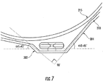
- the first angle ⁇ 1 can be selected to be equal to the second angle ⁇ 2, for example a 45° angle, such that the first angle 61 and second angle 62 have a sum of 90°.
- the first angle ⁇ 1 and the second angle ⁇ 2 of the first and second sidewalls 302, 304 with respect to the bottom wall 306 may not sum to 90°.
- the water consumption of the exemplary washer may be different (e.g., increased or reduced) compared to the water consumption requirements of conventional washers.
- the heater pocket 300 can be configured to cause the washing liquid L flowing in the heater pocket 300 to swirl or rotate within the heater pocket 300, thereby forcing the washing liquid into the space below the heater coils 404 and improving the cleaning out of accumulated debris from under, on, or around the heater coils 404.
- one or more interior surfaces of the sidewalls (e.g., 302, 304) or bottom wall 306 of the heater pocket 300 can include an optional diverter 500 for diverting the washing fluid or the washing fluid flow.
- the diverter 500 can generate a vortex or another flow pattern that improves the cleaning out of accumulated debris from under, on, or around the heater coils 404.
- the diverter 500 can include, for example, one or more of a fin, a dimple, a raised feature extending from a surface of the sidewalls 302, 304, and/or bottom wall 306, or a depressed feature extending into a surface of one or more of the sidewalls 302, 304, and/or bottom wall 306.
- the diverter 500 can be square-shaped, oval-shaped, circular-shaped, or another shape.
- the exemplary embodiments can cause the washing liquid L flowing in the heater pocket 300 to have a flow pattern within the heater pocket 300 that prevents or reduces the accumulation or collection of debris on, around, or below the heater coils 404, thereby increasing or maintaining the heat distribution from the heater coils 404 to the washing liquid L, extending the operating life of the heater coils 404, and increasing the overall efficiency of the washer.
- a household appliance includes a housing 110 having a door 112 formed in a front panel thereof for accessing an interior of the housing 110, and a tub 210 disposed inside the housing 110, the tub 210 having a rotating drum 215 therein for receiving laundry through the door 112, the drum 215 having an axis of rotation, wherein the tub 215 includes a heater pocket 300 integrally formed in a lower portion of the tub 215, the heater pocket 300 forming a cavity in fluid communication with the drum 215, the heater pocket 300 for at least partially surrounding a heating element 400 for heating a washing liquid L in the tub 215, wherein a cross-section of the heater pocket 300, which is taken in a direction substantially perpendicular to the axis of rotation of the rotating drum, includes a first sidewall 302, a second sidewall 304 opposed to the first sidewall 302, and a bottom wall 306 connecting a lower side of the first sidewall 302 to a lower side of the second sidewall
- the tub 215 includes a heater pocket 300 integrally formed in a lower portion of the tub 215, the heater pocket
- the exemplary embodiments can prevent or reduce the collection or accumulation of debris, such as fluffs (e.g., lint or paper particles) and lime, below, on, or around the heater coils 404.
- debris such as fluffs (e.g., lint or paper particles) and lime
- the exemplary embodiments provide important advantages in that, when the flow of the washing liquid is induced by the rotation of the drum 215, the resulting flow may slow down in the area of the heating element 404, since the heater pocket 300 may act like a diffuser.
- the flow of the washing liquid may substantially follow the shape of the tub 210, thereby providing sufficient washout below, on, or around the heating element 404 and/or the heater coil retainer clip 402.
- the exemplary embodiments also can facilitate uniform distribution of flow within the heater pocket 300 in the main flow direction, with only minor secondary flow components in other directions. A uniform flow pattern can be provided below and around the heater coils 404.
- the exemplary embodiments also can provide substantially uniform velocities of high magnitude below and around the heater coils 404. In this manner, the exemplary embodiments can increase the sweeping or cleaning affect of the washing liquid on the heater coils 404, thereby removing some or all of the accumulated debris from the heater coils 404 and/or the heater coil retainer clip 402. The exemplary embodiments may extend the operating life of the heater coils 404 and increase the heat distribution from the heater coils 404 to the washing liquid, thereby increasing the efficiency of the washer.
- spatially relative terms such as “under”, “below”, “lower”, “over”, “upper”, “lateral”, “left”, “right” and the like, may be used herein for ease of description to describe one element or feature's relationship to another element(s) or feature(s) as illustrated in the figures. It will be understood that the spatially relative terms are intended to encompass different orientations of the device in use or operation in addition to the orientation depicted in the figures. For example, if the device in the figures is inverted, elements described as “under” or “beneath” other elements or features would then be oriented “over” the other elements or features. The device may be otherwise oriented (rotated 90 degrees or at other orientations) and the descriptors of relative spatial relationships used herein interpreted accordingly.
Landscapes
- Engineering & Computer Science (AREA)
- Textile Engineering (AREA)
- Detail Structures Of Washing Machines And Dryers (AREA)
- Main Body Construction Of Washing Machines And Laundry Dryers (AREA)
- Packages (AREA)
Description
- The present invention is directed toward a household appliance, and more specifically, toward a household appliance having a heater pocket, known, for instance, from
E P-A- 1 975 298 . - A household appliance, such as a front-loading clothes washer includes a housing having a door providing access to a washing unit in the interior of the appliance housing. The washing unit includes a tub having a cylindrical washing drum rotatably mounted inside the tub. In operation, clothes or laundry are inserted into the washer through the door and placed in the rotating washing drum inside the tub. The household appliance wets the laundry to be washed with washing liquid and mechanically moves the laundry to release contaminants from the laundry. A drive system rotates the washing drum inside the tub about an axis of the drum.
- A heating element commonly is provided for heating the washing liquid in the tub of the washer. The heating element may be disposed in a heater pocket or cavity formed in the tub of the washer. In operation, the washing liquid flows into the heater pocket and over the heating element, such that heat is transferred from the heating element to the washing liquid, thereby raising the temperature of the washing liquid. The heated washing liquid then flows out of the heater pocket and into the washing drum for washing the laundry.
- A partial cross-sectional view of a conventional washer is illustrated in
FIG. 8 . The washer hasdrum 1215 rotatably mounted in atub 1210. Thetub 1210 includes aheater pocket 1300. Theheater pocket 1300 has afirst sidewall 1302, asecond sidewall 1304 that is opposed to thefirst sidewall 1302, and a third wall orbottom wall 1306 connecting thefirst sidewall 1302 to thesecond sidewall 1304, thereby forming a generally rectangular, box-shaped cavity. Thefirst sidewall 1302 is substantially parallel to thesecond sidewall 1304. The first andsecond sidewalls bottom wall 1306. In this manner, theheater pocket 1300 is capable of receiving a predetermined volume of washing liquid therein. - A
plate 1502 is disposed on thebottom wall 1306 of theheater pocket 1300. Aheating element clip 402 is coupled to theplate 1502. A heating element havingheater coils 404 and abase 406 is inserted into and sealingly engaged with an opening at a far end of theheater pocket 1300, as viewed inFIG. 8 . Theheater coils 404 engage and are retained by theheating element clip 402. The heating element can be, for example, a 1300 Watt heating element. - During a washing cycle of the washer, the rotation of the
drum 1215 induces a flow of the washing liquid from thedrum 1215 into theheater pocket 1300 to be heated by theheater coils 404 and then out of theheater pocket 1300 and back into thedrum 1215. - The
heater pocket 1300 is in fluid communication with a drain assembly (not shown) at a near end of theheater pocket 1300 as viewed inFIG. 8 , which can include a discharge pump and corrugated tubing for discharging the washing liquid from thetub 1210. During a draining cycle of the washer, the drain is opened and the washing liquid flows from thedrum 1215 into theheater pocket 1300, and then from theheater pocket 1300 into the corrugated tubing of the drain assembly. A discharge pump can be provided for drawing the washing liquid from theheater pocket 1300 and thetub 1210 into the drain assembly. - The present invention recognizes that the flow patterns of the washing liquid into, within, and out of the heater pocket can affect the heat distribution from the heater coils to the washing liquid, and thus the efficiency of the washer. The present invention further recognizes that the deposition and accumulation of debris below, on, or around the heater coils can affect the heat distribution from the heater coils to the washing liquid, thereby reducing the efficiency of the washer. The deposition and accumulation of debris below, on, or around the heater coils also can result in early failure of the heating element, thereby affecting the durability and reliability of the washer.
- As explained above with reference to
FIG. 8 , in many conventional washers, theheater pocket 1300 has a generally rectangular, box-shaped design in which thefirst sidewall 1302 is substantially parallel to thesecond sidewall 1304, and the first andsecond sidewalls bottom wall 1306. The conventional heater pocket may result in irregular flow patterns below and around the heating element, thereby reducing or limiting the heat distribution from the heater coils to the washing liquid. - For example, the sharp edges of the
heater pocket 1300 where thesidewalls tub 1210, as well as thevertical sidewalls heater pocket 1300 themselves, can induce irregular and heavily disturbed flow of the washing liquid under and around theheater coils 404. Also, the conventional heater pocket may reduce or limit the drainage efficiency to the discharge pump. The dynamics of the drum motion (i.e., rotation or oscillation) also can induce irregular flow patterns of the washing liquid below and around the heating element. The washing liquid can flow in a plurality of directions and at various velocities. Thus, with theconventional heater pocket 1300, there may be, for example, areas having irregular flow, areas in which the flow velocity is reduced, and/or stagnant areas (i.e., areas of minimal or no flow) below or around theheater coils 404. As a result, the efficiency of the heat distribution from theheater coils 404 to the washing liquid can be reduced. Also, the time to heat the washing liquid in the tub can be increased. - The present invention recognizes that these areas having irregular flow, areas in which the flow velocity is reduced, and/or stagnant areas below or around the
heater coils 404 can result in a large amount of debris, such as fluffs (e.g., lint or paper particles) and lime, collecting and accumulating under, on, or around theheater coils 404, since the flow may not be sufficient to sweep or clean this debris off of theheater coils 404 or out from under theheater coils 404. This debris can collect or accumulate under, on, or around theheater coils 404, and eventually, can turn into a paste-like material or coating on theheater coils 404 that may function like a layer of insulation on theheater coils 404. This debris also can collect or accumulate on the heater coil retainer clip. - In this manner, some of the most affected areas of the
heater coils 404 may eventually lose some or all of their ability to transfer heat to the washing liquid. As a result, the time to heat the washing liquid in the tub can be increased. As more and more debris accumulates on theheater coils 404, the time to heat the washing liquid can become longer. - Moreover, the insulating effect of the accumulated debris may cause overheating of the heating element, thereby resulting in early failure of the heating element and reducing the reliability of the washer.
- As explained above, during a draining cycle of the washer, the washing liquid flows from the
drum 1215 into theheater pocket 1300, and then exits theheater pocket 1300 through a drain via the discharge pump and corrugated tubing. The configuration of theconventional heater pocket 1300, and particularly the first andsecond sidewalls heater pocket 1300 being substantially perpendicular to thebottom wall 1306, can result in poor drainage from thetub 1210 to the discharge pump, for example, because the washing liquid may not flow smoothly into theheater pocket 1300 and/or may not flow smoothly within/from theheater pocket 1300 toward the drain. - A washer comprising a tub, a drum and a heating element is also know from
EP 1 975 298 A1 . The tub of such washer includes a heater pocket integrally formed in a lower portion of the tub and having two opposed sidewalls which are connected to a bottom wall wherein each of these sidewalls intersects the bottom wall at an angle other than 90°. - These problems and others are addressed by the present invention according to claim 1. A first exemplary embodiment comprises a household appliance including a housing having a door formed in a front panel thereof for accessing an interior of the housing, and a tub disposed inside the housing, the tub having a rotating drum therein for receiving laundry through the door, the drum having an axis of rotation, wherein the tub includes a heater pocket integrally formed in a lower portion of the tub, the heater pocket forming a cavity in fluid communication with the drum, the heater pocket for at least partially surrounding a heating element for heating a washing liquid in the tub, wherein a cross-section of the heater pocket, which is taken in a direction substantially perpendicular to the axis of rotation of the rotating drum, includes a first sidewall; a second sidewall opposed to the first sidewall; and a bottom wall connecting a lower side of the first sidewall to a lower side of the second sidewall, wherein each of the first sidewall and the second sidewall intersects the bottom wall at an angle other than 90°.
- Another exemplary embodiment of the invention comprises a front-loading washer including a housing having a door formed in a front panel thereof for accessing an interior of the housing, and a tub disposed inside the housing, the tub having a rotating drum therein for receiving laundry through the door, the drum having an axis of rotation. The tub includes a heater pocket integrally formed in a lower portion of the tub, the heater pocket forming a cavity in fluid communication with the drum, the heater pocket for at least partially surrounding a heating element for heating a washing liquid in the tub, wherein walls of the heater pocket guides the washing liquid one of below and around the heating element at a substantially constant velocity and with a substantially uniform flow pattern.
- Another exemplary embodiment of the invention comprises a front-loading washer including a housing having a door formed in a front panel thereof for accessing an interior of the housing; and a tub disposed inside the housing, the tub having a rotating drum therein for receiving laundry through the door, the drum having an axis of rotation, wherein the tub includes a heater pocket integrally formed in a lower portion of the tub, the heater pocket forming a cavity in fluid communication with the drum, the heater pocket for at least partially surrounding a heating element for heating a washing liquid in the tub, wherein the heater pocket includes means for guiding the washing liquid one of below and around the heater coil at a substantially constant velocity and with a substantially uniform flow pattern.
- In this manner, the exemplary embodiments can provide a heater pocket that promotes substantially uniform flow and velocity of the washing liquid in the heater pocket, including below and around the heater coil and out of the heater pocket during a heating cycle. The exemplary embodiments can increase the heat distribution from the heater coils to the washing liquid. Also, the exemplary embodiments can reduce the time to heat the washing liquid in the tub. Furthermore, the exemplary embodiments can increase the drainage efficiency to the discharge pump and reduce the resistance of the flow of the washing liquid into the drain.
- The exemplary embodiments can promote uniform flow of the washing liquid into the drain assembly during draining of the washing liquid, for example, during a spinning cycle. In this manner, the disclosed exemplary embodiments can reduce or eliminate stagnant areas, low flow areas, or irregular flow areas that may result in large amounts of debris collecting under, on, or around the heater coils. The exemplary embodiments can prevent or reduce the collection or accumulation of debris, such as fluffs (e.g., lint or paper particles) and lime deposits or formations under, on, or around the heater coils.
- Moreover, the exemplary embodiments can promote substantially uniform velocity of the washing liquid below and around the heater coils. In an exemplary embodiment, one or more interior surfaces of the first or second sidewalls or the bottom wall of the heater pocket can include an optional diverter for diverting the washing fluid or the washing fluid flow. The diverter can generate a vortex or other flow pattern that improves the cleaning out of accumulated debris under or on the heater coils. In this manner, the exemplary embodiments can induce sufficient velocity of the washing liquid to provide a sweeping or cleaning affect on the heater coils, thereby removing some or all of the collected debris from the heater coils. The exemplary embodiments may extend the operating life of the heater coils and increase the heat distribution from the heater coils to the washing liquid, thereby increasing the efficiency of the washer.
- Other features and advantages of the present invention will become apparent to those skilled in the art upon review of the following detailed description and drawings.
- These and other aspects and features of embodiments of the present invention will be better understood after a reading of the following detailed description, together with the attached drawings, wherein:
-
Figure 1 is a front elevation view of a washer; -
Figure 2 is a side elevation view of a washing unit according to an exemplary embodiment of the invention; -
Figure 3 is a rear elevation view of the washing unit ofFigure 2 ; -
Figure 4 is a partial cross-sectional view of a heater pocket according toFigure 2 taken along the line IV-IV; -
Figure 5 is another partial cross-sectional view of a heater pocket ofFigure 2 taken along the line IV-IV according to an exemplary embodiment of the invention; -
Figure 6 is another partial cross-sectional view of a heater pocket ofFigure 2 taken along the line IV-IV according to an exemplary embodiment of the invention; -
Figure 7 is a partial cross-sectional view of a heater pocket ofFigure 2 taken along the line IV-IV according to another exemplary embodiment of the invention; and -
Figure 8 is a partial cross-sectional view of a conventional heater pocket. - The present invention now is described more fully hereinafter with reference to the accompanying drawings, in which embodiments of the invention are shown. This invention may, however, be embodied in many different forms and should not be construed as limited to the embodiments set forth herein; rather, these embodiments are provided so that this disclosure will be thorough and complete, and will fully convey the scope of the invention to those skilled in the art.
- Referring now to the drawings,
Figures 1 - 7 illustrate exemplary embodiments of a household appliance having a heater pocket according to exemplary embodiments of the present invention. -
FIG. 1 illustrates ahousehold appliance 100, such as a front-loading clothes washer, having ahousing 110 and adoor 112 to provide access to the interior of theappliance housing 110. Thehousehold appliance 100 wets the laundry to be washed with washing liquid and mechanically moves the laundry to release contaminants from the laundry. - With reference to
FIGS. 2-4 , thehousing 110 encloses a washing unit, which includes atub 210 having arotating washing drum 215 that rotates or oscillates about an axis to move the clothes or laundry in thetub 210. The interior of thetub 210 is accessible through theopening 212, which corresponds to thedoor 112 of thehousing 110, as illustrated inFIG. 1 . In operation, a drive system rotates or oscillates therotating washing drum 215 within thetub 210. The drive system can include, for example, amotor 214, apulley 216, and adrive belt 218. - As shown in
FIGS. 2 and3 , thetub 210 can include aheater pocket 300 having aheating element 400 disposed therein. The washing unit also can include adrain assembly 220 coupled to or formed in thetub 210. Thedrain assembly 220 can be in fluid communication with theheater pocket 300. Thedrain assembly 220 can include, for example, a discharge pump and corrugated tube for discharging the washing liquid from thetub 210. - With reference to
FIG. 4 , theheater pocket 300 can include afirst sidewall 302, asecond sidewall 304, and abottom wall 306. Aplate 502 can be coupled to or integrally formed with thebottom wall 306 of theheater pocket 300. A heatercoil retainer clip 402 can be coupled to theplate 502. During assembly of the household appliance, aheating element 400 havingheater coils 404 and a base 406 can be inserted into and sealingly engaged with an opening at the far end of theheater pocket 300, as viewed inFIG. 4 . The heater coils 404 engage and are retained by the heatingelement retainer clip 402. Theheating element 400 can be, for example, a 300 Watt heating element. - In an exemplary embodiment, the interior surface of the
first sidewall 302 and the interior surface of thesecond sidewall 304 can have a draft angle to assist with removal of the heater pocket from a mold during a manufacturing process. For example, the interior surface of thefirst sidewall 302 and the interior surface of thesecond sidewall 304 can be closer to each other at the far end of the heater pocket where thebase 406 of theheating element 400 engages the heater pocket, as viewed inFIG. 4 , than at the near end of the heater pocket having the drain assembly (not shown) as viewed inFIG. 4 . - In an exemplary embodiment, the interior surface of the
bottom wall 306 can be sloped in a direction toward thedrain assembly 220 to promote the flow of the washing liquid L toward and into thedrain assembly 220, as shown inFIG. 2 . The drain assembly 220 (not shown inFIG. 4 ) is located at the near end of theheater pocket 300 as viewed inFIG. 4 (i.e., at an opposite end from thebase 406 of the heating element 400). An opening into the drain assembly from the heater pocket can include a mesh screen, for example a metal screen, that prevents or reduces the flow of debris from theheater pocket 300 into the drain assembly. - The exemplary embodiments of
FIGS. 4-6 illustrate a cross-section of the heater pocket taken in a direction substantially perpendicular to the axis of rotation of thedrum 215. In the exemplary embodiments, the cross-section of thebottom wall 306 can be substantially parallel to the heater coils 404 of theheating element 400. - In cross-section of the
heater pocket 300, thefirst sidewall 302 and thesecond sidewall 304 of theheater pocket 300 are not perpendicular to thebottom wall 306. That is, thefirst sidewall 302 and thesecond sidewall 304 of theheater pocket 300 can be inclined at an angle other than 90° with respect to thebottom wall 306. For example, when viewed in cross-section, thefirst sidewall 302 can be inclined by a first angle θ1 and thesecond sidewall 304 can be inclined at a second angle θ2 with respect to thebottom wall 306. By providing the cross-sections of thefirst sidewall 302 andsecond sidewall 304 at angles other than 90° with respect to thebottom wall 306, the exemplary embodiments can eliminate or reduce a number of features, such as sharp corners, that may be prone to collecting or accumulating debris, such as fluffs (e.g., lint or paper particles) and deposits or formation of lime. - During operation, the rotation of the
drum 215 induces flow of the washing liquid into theheater pocket 300 in a first direction. Thedrum 215 can include paddle-shaped elements thereon for lifting or pushing the washing liquid L as thedrum 215 rotates, thereby inducing flow of the washing liquid L into the heater pocket in a first direction and then out of the other side of the heater pocket. The rotation of thedrum 215 also may result in a backflow of a portion of the washing liquid into theheater pocket 300 in a second direction as a result of some of the washing liquid that is dragged or lifted out of the heater pocket by the rotating drum subsequently flowing back into the heater pocket. - During a heating cycle, the washing liquid flows from the
drum 215 into theheater pocket 300, wherein the heater coils transfer heat to the washing liquid. The heated washing liquid then flows out of theheater pocket 300 and back into thedrum 215. Similarly, during a rinsing cycle, the washing liquid flows from thedrum 215 into theheater pocket 300 and then out of theheater pocket 300 and back into thedrum 215. During the heating and/or rinsing cycles, thedrum 215 may rotate in a first direction (e.g., a clockwise direction) for a period of time, and then rotate in a second direction (e.g., a counter-clockwise direction) for a period of time. - During a draining cycle of the washer, for example a spinning cycle, the washing liquid flows into the
heater pocket 300 from thedrum 215, and then is permitted to flow into, or be drawn into, thedrain assembly 220. As explained above, a discharge pump can be provided for drawing the washing liquid from theheater pocket 300 and thetub 210 into thedrain assembly 220. During the draining cycle, thedrum 215 may rotate in a single direction such that the washing liquid flows into theheater pocket 300 in a single direction, for example, a clockwise direction inFigures 4-7 . - In an exemplary embodiment, the configuration of the
first sidewall 302,second sidewall 304, andbottom wall 306 can facilitate substantially uniform flow and velocity of the washing liquid below and around the heater coils 404, thereby reducing or eliminating stagnant areas, low flow areas, or irregular flow areas in which large amounts of debris can collect and accumulate under, on, or around the heater coils 404. As a result, the exemplary embodiments can improve water flow and heat distribution from the heater coils 404 to the washing liquid, thereby increasing the efficiency of the washer. Also, the exemplary embodiments can reduce the time to heat the washing liquid L in thetub 210. - The
first sidewall 302,second sidewall 304, andbottom wall 306 also can be configured in a manner to promote the flow of the washing liquid into thedrain assembly 220. As a result, the exemplary embodiments can increase the drainage efficiency of the washer. - With reference again to the cross-section of the exemplary heater pocket illustrated in
FIGS. 5 and6 , thefirst sidewall 302 intersects thebottom wall 306 at a first angle θ1, and thesecond sidewall 304 intersects thebottom wall 306 at a second angle θ2. The first angle θ1 and second angle θ2 can be selected to promote uniform flow of washing liquid L (illustrated using dashed lines inFIG. 5 ) into theheater pocket 300, below and around theheater coil 404, and out of theheater pocket 300, for example during a heating cycle, as well as to promote the flow of water into theheater pocket 300 and into thedrain assembly 220, for example during a spinning cycle. - In the exemplary heater pocket illustrated in
FIGS. 4-6 , first angle θ1 can be selected to be lower than the second angle θ2 to increase the velocity of the washing liquid flowing into theheater pocket 300. The first angle θ1 can be selected such that thefirst sidewall 302 does not restrict the flow of washing liquid into theheater pocket 300 for heating by theheating element 400. The second angle θ2 can be selected to be higher than the first angle θ1 to increase the velocity of the washing liquid flowing into thedrain assembly 220, for example, during a spinning cycle of the washer. The second angle θ2 can promote flow of the washing fluid into thedrain assembly 220 from theheater pocket 300 in a clockwise direction. - In an exemplary embodiment, a ratio of the second angle θ2 to the first angle θ1 can be selected to be a 2 to 1 ratio (e.g., 60° to 30° as illustrated in
FIG. 6 ), thereby promoting a higher velocity of washing fluid flowing into theheater pocket 300 during heating, and improving flow of the washing fluid toward the drain during a draining or spinning cycle of the washer. One of ordinary skill will recognize that other ratios of the second angle θ2 to the first angle θ1 are possible within the spirit and scope of the invention and are contemplated by the present invention. - With reference to
FIG. 6 , the first angle θ1 and the second angle θ2 can be selected such that their sum is equal to 90°. In this manner, the exemplary embodiments can provide aheater pocket 300 that does not increase the volume requirement of the washing liquid in the washer as compared to the conventional heater pocket, such that the water consumption of the exemplary washer is consistent with the water consumption requirements of conventional washers. - As explained above, in the exemplary heater pocket illustrated in
FIG. 6 , the first angle 61 can be 30° and the second angle 62 can be 60°, thereby providing a 2 to 1 ratio. In other exemplary embodiments, the first angle θ1 and second angle θ2 can include other angles having a sum of 90°. For example, as illustrated inFIG. 7 , the first angle θ1 can be selected to be equal to the second angle θ2, for example a 45° angle, such that the first angle 61 and second angle 62 have a sum of 90°. - In still other exemplary embodiments, the first angle θ1 and the second angle θ2 of the first and
second sidewalls bottom wall 306 may not sum to 90°. In these cases, the water consumption of the exemplary washer may be different (e.g., increased or reduced) compared to the water consumption requirements of conventional washers. - In another exemplary embodiment, the
heater pocket 300 can be configured to cause the washing liquid L flowing in theheater pocket 300 to swirl or rotate within theheater pocket 300, thereby forcing the washing liquid into the space below the heater coils 404 and improving the cleaning out of accumulated debris from under, on, or around the heater coils 404. For example, as illustrated inFigure 4 , one or more interior surfaces of the sidewalls (e.g., 302, 304) orbottom wall 306 of theheater pocket 300 can include anoptional diverter 500 for diverting the washing fluid or the washing fluid flow. Thediverter 500 can generate a vortex or another flow pattern that improves the cleaning out of accumulated debris from under, on, or around the heater coils 404. Thediverter 500 can include, for example, one or more of a fin, a dimple, a raised feature extending from a surface of thesidewalls bottom wall 306, or a depressed feature extending into a surface of one or more of thesidewalls bottom wall 306. - For example, the
diverter 500 can be square-shaped, oval-shaped, circular-shaped, or another shape. In this manner, the exemplary embodiments can cause the washing liquid L flowing in theheater pocket 300 to have a flow pattern within theheater pocket 300 that prevents or reduces the accumulation or collection of debris on, around, or below the heater coils 404, thereby increasing or maintaining the heat distribution from the heater coils 404 to the washing liquid L, extending the operating life of the heater coils 404, and increasing the overall efficiency of the washer. - To summarize, according to a disclosed exemplary embodiment, a household appliance is provided. The exemplary household appliance includes a
housing 110 having adoor 112 formed in a front panel thereof for accessing an interior of thehousing 110, and atub 210 disposed inside thehousing 110, thetub 210 having arotating drum 215 therein for receiving laundry through thedoor 112, thedrum 215 having an axis of rotation, wherein thetub 215 includes aheater pocket 300 integrally formed in a lower portion of thetub 215, theheater pocket 300 forming a cavity in fluid communication with thedrum 215, theheater pocket 300 for at least partially surrounding aheating element 400 for heating a washing liquid L in thetub 215, wherein a cross-section of theheater pocket 300, which is taken in a direction substantially perpendicular to the axis of rotation of the rotating drum, includes afirst sidewall 302, asecond sidewall 304 opposed to thefirst sidewall 302, and abottom wall 306 connecting a lower side of thefirst sidewall 302 to a lower side of thesecond sidewall 304, wherein each of thefirst sidewall 302 and thesecond sidewall 304 intersects thebottom wall 306 at an angle other than 90°. - Another exemplary embodiment of the invention comprises a front-loading washer including a
housing 110 having adoor 112 formed in a front panel thereof for accessing an interior of thehousing 110, and atub 210 disposed inside thehousing 110, thetub 210 having arotating drum 215 therein for receiving laundry through thedoor 112, thedrum 215 having an axis of rotation, wherein thetub 215 includes aheater pocket 300 integrally formed in a lower portion of thetub 215, theheater pocket 300 forming a cavity in fluid communication with thedrum 215, theheater pocket 300 for at least partially surrounding aheating element 400 for heating a washing liquid L in thetub 215, whereinwalls heater pocket 300 guide the washing liquid L one of below and around theheating element 400 at a substantially constant velocity and with a substantially uniform flow pattern. - Another exemplary embodiment of the invention comprises a front-loading washer including a
housing 110 having adoor 112 formed in a front panel thereof for accessing an interior of thehousing 110, and atub 210 disposed inside thehousing 110, thetub 210 having arotating drum 215 therein for receiving laundry through thedoor 112, thedrum 215 having an axis of rotation, wherein thetub 215 includes aheater pocket 300 integrally formed in a lower portion of thetub 215, theheater pocket 300 forming a cavity in fluid communication with thedrum 215, theheater pocket 300 for at least partially surrounding aheating element 400 for heating a washing liquid L in thetub 215, wherein theheater pocket 300 includes means for guiding (e.g., 302, 304, 306, 550, θ1, θ2, and combinations thereof) the washing liquid L one of below and around theheating element 400 at a substantially constant velocity and with a substantially uniform flow pattern. - As explained above, these features are important for providing a household appliance having a heater pocket that can promote uniform flow of the washing liquid below, on, or around the heater coils 404, thereby reducing or eliminating stagnant areas, low flow areas, or irregular flow areas where large amounts of debris can collect on the heater coils 404. In this manner, the exemplary embodiments can prevent or reduce the collection or accumulation of debris, such as fluffs (e.g., lint or paper particles) and lime, below, on, or around the heater coils 404.
- The exemplary embodiments provide important advantages in that, when the flow of the washing liquid is induced by the rotation of the
drum 215, the resulting flow may slow down in the area of theheating element 404, since theheater pocket 300 may act like a diffuser. The flow of the washing liquid may substantially follow the shape of thetub 210, thereby providing sufficient washout below, on, or around theheating element 404 and/or the heatercoil retainer clip 402. The exemplary embodiments also can facilitate uniform distribution of flow within theheater pocket 300 in the main flow direction, with only minor secondary flow components in other directions. A uniform flow pattern can be provided below and around the heater coils 404. - The exemplary embodiments also can provide substantially uniform velocities of high magnitude below and around the heater coils 404. In this manner, the exemplary embodiments can increase the sweeping or cleaning affect of the washing liquid on the heater coils 404, thereby removing some or all of the accumulated debris from the heater coils 404 and/or the heater
coil retainer clip 402. The exemplary embodiments may extend the operating life of the heater coils 404 and increase the heat distribution from the heater coils 404 to the washing liquid, thereby increasing the efficiency of the washer. - The present invention has been described herein in terms of several preferred embodiments. However, modifications and additions to these embodiments will become apparent to those of ordinary skill in the art upon a reading of the foregoing description.
- Like numbers refer to like elements throughout. In the figures, the thickness of certain lines, layers, components, elements or features may be exaggerated for clarity.
- The terminology used herein is for the purpose of describing particular embodiments only and is not intended to be limiting of the invention. Unless otherwise defined, all terms (including technical and scientific terms) used herein have the same meaning as commonly understood by one of ordinary skill in the art to which this invention belongs. It will be further understood that terms, such as those defined in commonly used dictionaries, should be interpreted as having a meaning that is consistent with their meaning in the context of the specification and relevant art and should not be interpreted in an idealized or overly formal sense unless expressly so defined herein. Well-known functions or constructions may not be described in detail for brevity and/or clarity.
- As used herein, the singular forms "a", "an" and "the" are intended to include the plural forms as well, unless the context clearly indicates otherwise. It will be further understood that the terms "comprises" and/or "comprising," when used in this specification, specify the presence of stated features, integers, steps, operations, elements, and/or components, but do not preclude the presence or addition of one or more other features, integers, steps, operations, elements, components, and/or groups thereof. As used herein, the term "and/or" includes any and all combinations of one or more of the associated listed items. As used herein, phrases such as "between X and Y" and "between about X and Y" should be interpreted to include X and Y. As used herein, phrases such as "between about X and Y" mean "between about X and about Y." As used herein, phrases such as "from about X to Y" mean "from about X to about Y."
- It will be understood that when an element is referred to as being "on", "attached" to, "connected" to, "coupled" with, "contacting", etc., another element, it can be directly on, attached to, connected to, coupled with or contacting the other element or intervening elements may also be present. In contrast, when an element is referred to as being, for example, "directly on", "directly attached" to, "directly connected" to, "directly coupled" with or "directly contacting" another element, there are no intervening elements present. It will also be appreciated by those of skill in the art that references to a structure or feature that is disposed "adjacent" another feature may have portions that overlap or underlie the adjacent feature.
- Spatially relative terms, such as "under", "below", "lower", "over", "upper", "lateral", "left", "right" and the like, may be used herein for ease of description to describe one element or feature's relationship to another element(s) or feature(s) as illustrated in the figures. It will be understood that the spatially relative terms are intended to encompass different orientations of the device in use or operation in addition to the orientation depicted in the figures. For example, if the device in the figures is inverted, elements described as "under" or "beneath" other elements or features would then be oriented "over" the other elements or features. The device may be otherwise oriented (rotated 90 degrees or at other orientations) and the descriptors of relative spatial relationships used herein interpreted accordingly.
Claims (15)
- A household appliance (100) comprising:a housing (110) having a door (112) formed in a front panel thereof for accessing an interior of the housing (110); and a tub (210) disposed inside the housing (110), the tub (210) having a rotating drum (215) therein for receiving laundry through the door (112), the drum (215) having an axis of rotation,wherein the tub (210) includes: a heater pocket (300) integrally formed in a lower portion of the tub (210), the heater pocket (300) forming a cavity in fluid communication with the drum (215), the heater pocket (300) for at least partially surrounding a heating element (400) for heating a washing liquid in the tub (210),wherein a cross-section of the heater pocket (300), which is taken in a direction substantially perpendicular to the axis of rotation of the rotating drum (215), includes: a first sidewall (302); a second sidewall (304) opposed to the first sidewall (302); and a bottom wall (306) connecting a lower side of the first sidewall (302) to a lower side of the second sidewall (304),wherein each of the first sidewall (302) and the second sidewall (304) intersects the bottom wall (306) at an angle other than 90°, characterized in thatan interior surface of one or more of the first sidewall (302), the second sidewall (304) and the bottom wall (306) includes a diverter (500) for diverting the washing liquid or the washing liquid flow.
- The household appliance (100) of claim 1, wherein the diverter (500) is a fin, a dimple, a raised feature extending from the first and/or second sidewall (302, 304) and/or from the bottom wall (306) or a depressed feature extending into a surface of the first and/or second sidewall (302, 304) and/or into the bottom wall (306).
- The household appliance (100) of claim 1 or claim 2, wherein the diverter (500) is designed for generating a vortex.
- The household appliance (100) of one of the claims 1 to 3, comprising a heating element (400) having a heater coil (404) disposed in the heater pocket (300).
- The household appliance (100) of claim 4, wherein the diverter (500) is designed for generating a flow pattern which improves the cleaning out of accumulated debris under or on the heater coil (404).
- The household appliance (100) of one of the claims 1 to 5, wherein the first sidewall (302) is perpendicular to the second sidewall (304).
- The household appliance (100) of one of the claims 1 to 6, wherein a sum of the first angle θ1 angled between the first sidewall (302) and the bottom wall (306) and the second angle θ2 angled between the second sidewall (304) and the bottom wall (306) is 90°.
- The household appliance (100) of one of the claims 1 to 6, wherein the first angle θ1 angled between the first sidewall (302) and the bottom wall (306) is less than the second angle θ2 angled between the second sidewall (304) and the bottom wall (306).
- The household appliance (100) of one of the claims 1 to 6, wherein a ratio of the second angle θ2 angled between the second sidewall (304) and the bottom wall (306) to the first angle θ1 angled between the first sidewall (302) and the bottom wall (306) is a 2 to 1 ratio.
- The household appliance (100) of one of the claims 1 to 6, wherein the first angle θ1 angled between the first sidewall (302) and the bottom wall (306) is equal to the second angle θ2 angled between the second sidewall (304) and the bottom wall (306).
- The household appliance (100) of one of the claims 4 to 10, wherein the bottom wall (306) is substantially parallel to the heater coil (404) of the heating element (400).
- The household appliance (100) of one of the claim 4 to 11, wherein at least one of the first sidewall (302) and the second sidewall (304) guides the washing liquid one of below and around the heater coil (404).
- The household appliance (100) of one of the claims 4 to 12, wherein at least one of the first sidewall (302) and the second sidewall (304) guides the washing liquid such that the washing liquid rotates below the heater coil (404).
- The household appliance (100) of one of the claims 4 to 12, wherein an interior surface of at least one of the first sidewall (302) and the second sidewall guides (304) the washing liquid one of below and around the heater coil (404) at a substantially constant velocity and with a substantially uniform flow pattern.
- The household appliance (100) of one of the previous claims, wherein the heater pocket (300) includes: a drain for draining the washing liquid from the tub (210), wherein an interior surface of the bottom wall (306) of the heater pocket (300) is angled with respect to the axis of rotation of the drum toward the drain.
Applications Claiming Priority (2)
| Application Number | Priority Date | Filing Date | Title |
|---|---|---|---|
| US12/533,040 US20110023555A1 (en) | 2009-07-31 | 2009-07-31 | Heater pocket for a household appliance |
| PCT/EP2010/060827 WO2011012590A1 (en) | 2009-07-31 | 2010-07-27 | Heater pocket for a household appliance |
Publications (2)
| Publication Number | Publication Date |
|---|---|
| EP2459798A1 EP2459798A1 (en) | 2012-06-06 |
| EP2459798B1 true EP2459798B1 (en) | 2016-03-23 |
Family
ID=42731832
Family Applications (1)
| Application Number | Title | Priority Date | Filing Date |
|---|---|---|---|
| EP10737882.0A Not-in-force EP2459798B1 (en) | 2009-07-31 | 2010-07-27 | Heater pocket for a household appliance |
Country Status (7)
| Country | Link |
|---|---|
| US (1) | US20110023555A1 (en) |
| EP (1) | EP2459798B1 (en) |
| CN (1) | CN102482832B (en) |
| CA (1) | CA2709435A1 (en) |
| EA (1) | EA019026B1 (en) |
| PL (1) | PL2459798T3 (en) |
| WO (1) | WO2011012590A1 (en) |
Families Citing this family (3)
| Publication number | Priority date | Publication date | Assignee | Title |
|---|---|---|---|---|
| CN102844486B (en) * | 2010-04-30 | 2015-09-09 | Lg电子株式会社 | Clothes device |
| CN105862341B (en) * | 2015-01-23 | 2019-11-05 | 青岛海尔滚筒洗衣机有限公司 | Washing machine outer cylinder and washing machine |
| JP6937467B2 (en) * | 2018-02-27 | 2021-09-22 | パナソニックIpマネジメント株式会社 | Washing machine |
Family Cites Families (13)
| Publication number | Priority date | Publication date | Assignee | Title |
|---|---|---|---|---|
| IT1136452B (en) * | 1980-07-03 | 1986-08-27 | Zanussi A Spa Industrie | PLASTIC TANK FOR WASHING MACHINES |
| JPH10211393A (en) * | 1997-01-30 | 1998-08-11 | Matsushita Electric Ind Co Ltd | Drum type washing machine |
| AU753411B2 (en) * | 1999-10-19 | 2002-10-17 | Lg Electronics Inc. | Structure of driving unit in drum type washing machine |
| US6820447B2 (en) * | 2002-05-08 | 2004-11-23 | Whirlpool Corporation | Foreign objects trap for an automatic washer |
| US7454927B2 (en) * | 2003-10-31 | 2008-11-25 | Whirlpool Corporation | Method and apparatus adapted for recovery and reuse of select rinse fluid in a non-aqueous wash apparatus |
| KR20050076213A (en) * | 2004-01-20 | 2005-07-26 | 삼성전자주식회사 | Clothing dryer |
| KR20060082689A (en) * | 2005-01-13 | 2006-07-19 | 삼성전자주식회사 | How to wash a washing machine and laundry |
| US7677062B2 (en) * | 2005-10-25 | 2010-03-16 | General Electric Company | Washing machine with spraying device |
| KR20080087597A (en) * | 2007-03-27 | 2008-10-01 | 삼성전자주식회사 | washer |
| KR101168955B1 (en) * | 2007-05-16 | 2012-07-27 | 삼성전자주식회사 | Water softener and home appliances including the same |
| EP1995367B1 (en) * | 2007-05-16 | 2012-03-14 | Samsung Electronics Co., Ltd. | Washing machine having water softening device |
| KR20090071273A (en) * | 2007-12-27 | 2009-07-01 | 주식회사 대우일렉트로닉스 | Drum Washing Machine |
| PL2100996T3 (en) * | 2008-03-11 | 2016-06-30 | Whirlpool Co | Washing appliance with induction heating |
-
2009
- 2009-07-31 US US12/533,040 patent/US20110023555A1/en not_active Abandoned
-
2010
- 2010-07-12 CA CA2709435A patent/CA2709435A1/en not_active Abandoned
- 2010-07-27 PL PL10737882.0T patent/PL2459798T3/en unknown
- 2010-07-27 WO PCT/EP2010/060827 patent/WO2011012590A1/en not_active Ceased
- 2010-07-27 EP EP10737882.0A patent/EP2459798B1/en not_active Not-in-force
- 2010-07-27 CN CN201080033983.9A patent/CN102482832B/en not_active Expired - Fee Related
- 2010-07-27 EA EA201270194A patent/EA019026B1/en not_active IP Right Cessation
Also Published As
| Publication number | Publication date |
|---|---|
| WO2011012590A1 (en) | 2011-02-03 |
| CN102482832A (en) | 2012-05-30 |
| US20110023555A1 (en) | 2011-02-03 |
| EA201270194A1 (en) | 2012-08-30 |
| CA2709435A1 (en) | 2011-01-31 |
| CN102482832B (en) | 2015-10-21 |
| EA019026B1 (en) | 2013-12-30 |
| EP2459798A1 (en) | 2012-06-06 |
| PL2459798T3 (en) | 2016-09-30 |
Similar Documents
| Publication | Publication Date | Title |
|---|---|---|
| US9222209B2 (en) | Washing machine | |
| EP2453053B1 (en) | Laundry machine | |
| US9228290B2 (en) | Water level sensing apparatus, water supply hose and washing machine having the same | |
| CN103726267B (en) | Washing machine | |
| US6820447B2 (en) | Foreign objects trap for an automatic washer | |
| EP2455535B1 (en) | Washing machine | |
| EP2459798B1 (en) | Heater pocket for a household appliance | |
| CN110230172A (en) | Filtering device for washing machine and the washing machine for being equipped with the device | |
| US8485001B2 (en) | Household appliance having a tub with a fluid guide | |
| WO2013088940A1 (en) | Washing machine | |
| CN211546996U (en) | Washing machine without outer drum | |
| WO2024027744A1 (en) | Control method for washing device, and washing device | |
| CN204803573U (en) | Wave wheel washing machine | |
| CN216778101U (en) | Filter assembly and washing equipment | |
| JP2016518890A (en) | Washing machine provided with outer tub cover with spray device and its internal circulation spray method | |
| KR20050114341A (en) | A filtering apparatus of a washer | |
| CN223049015U (en) | Draining pump suitable for washing and drying integrated machine and washing and drying integrated machine | |
| CN223706034U (en) | Door body of washing equipment, detergent container and washing equipment | |
| US12460341B2 (en) | Washing machine device | |
| CN214244980U (en) | Distributor assembly and clothes treatment equipment | |
| CN222024744U (en) | Evaporator cleaning device and clothes treatment equipment | |
| CN217810112U (en) | Drum washing machine | |
| CN223576798U (en) | Front-loading washing machine | |
| JP2014033888A (en) | Washer | |
| WO2019192522A1 (en) | Clothing treatment device |
Legal Events
| Date | Code | Title | Description |
|---|---|---|---|
| PUAI | Public reference made under article 153(3) epc to a published international application that has entered the european phase |
Free format text: ORIGINAL CODE: 0009012 |
|
| 17P | Request for examination filed |
Effective date: 20120229 |
|
| AK | Designated contracting states |
Kind code of ref document: A1 Designated state(s): AL AT BE BG CH CY CZ DE DK EE ES FI FR GB GR HR HU IE IS IT LI LT LU LV MC MK MT NL NO PL PT RO SE SI SK SM TR |
|
| DAX | Request for extension of the european patent (deleted) | ||
| RAP1 | Party data changed (applicant data changed or rights of an application transferred) |
Owner name: BSH HAUSGERAETE GMBH |
|
| GRAP | Despatch of communication of intention to grant a patent |
Free format text: ORIGINAL CODE: EPIDOSNIGR1 |
|
| INTG | Intention to grant announced |
Effective date: 20151015 |
|
| GRAS | Grant fee paid |
Free format text: ORIGINAL CODE: EPIDOSNIGR3 |
|
| GRAA | (expected) grant |
Free format text: ORIGINAL CODE: 0009210 |
|
| AK | Designated contracting states |
Kind code of ref document: B1 Designated state(s): AL AT BE BG CH CY CZ DE DK EE ES FI FR GB GR HR HU IE IS IT LI LT LU LV MC MK MT NL NO PL PT RO SE SI SK SM TR |
|
| REG | Reference to a national code |
Ref country code: GB Ref legal event code: FG4D |
|
| REG | Reference to a national code |
Ref country code: CH Ref legal event code: EP |
|
| REG | Reference to a national code |
Ref country code: AT Ref legal event code: REF Ref document number: 783276 Country of ref document: AT Kind code of ref document: T Effective date: 20160415 |
|
| REG | Reference to a national code |
Ref country code: IE Ref legal event code: FG4D |
|
| REG | Reference to a national code |
Ref country code: DE Ref legal event code: R096 Ref document number: 602010031427 Country of ref document: DE |
|
| REG | Reference to a national code |
Ref country code: LT Ref legal event code: MG4D |
|
| REG | Reference to a national code |
Ref country code: NL Ref legal event code: MP Effective date: 20160323 |
|
| PG25 | Lapsed in a contracting state [announced via postgrant information from national office to epo] |
Ref country code: GR Free format text: LAPSE BECAUSE OF FAILURE TO SUBMIT A TRANSLATION OF THE DESCRIPTION OR TO PAY THE FEE WITHIN THE PRESCRIBED TIME-LIMIT Effective date: 20160624 Ref country code: NO Free format text: LAPSE BECAUSE OF FAILURE TO SUBMIT A TRANSLATION OF THE DESCRIPTION OR TO PAY THE FEE WITHIN THE PRESCRIBED TIME-LIMIT Effective date: 20160623 Ref country code: HR Free format text: LAPSE BECAUSE OF FAILURE TO SUBMIT A TRANSLATION OF THE DESCRIPTION OR TO PAY THE FEE WITHIN THE PRESCRIBED TIME-LIMIT Effective date: 20160323 Ref country code: FI Free format text: LAPSE BECAUSE OF FAILURE TO SUBMIT A TRANSLATION OF THE DESCRIPTION OR TO PAY THE FEE WITHIN THE PRESCRIBED TIME-LIMIT Effective date: 20160323 |
|
| REG | Reference to a national code |
Ref country code: AT Ref legal event code: MK05 Ref document number: 783276 Country of ref document: AT Kind code of ref document: T Effective date: 20160323 |
|
| PG25 | Lapsed in a contracting state [announced via postgrant information from national office to epo] |
Ref country code: LV Free format text: LAPSE BECAUSE OF FAILURE TO SUBMIT A TRANSLATION OF THE DESCRIPTION OR TO PAY THE FEE WITHIN THE PRESCRIBED TIME-LIMIT Effective date: 20160323 Ref country code: LT Free format text: LAPSE BECAUSE OF FAILURE TO SUBMIT A TRANSLATION OF THE DESCRIPTION OR TO PAY THE FEE WITHIN THE PRESCRIBED TIME-LIMIT Effective date: 20160323 Ref country code: NL Free format text: LAPSE BECAUSE OF FAILURE TO SUBMIT A TRANSLATION OF THE DESCRIPTION OR TO PAY THE FEE WITHIN THE PRESCRIBED TIME-LIMIT Effective date: 20160323 Ref country code: SE Free format text: LAPSE BECAUSE OF FAILURE TO SUBMIT A TRANSLATION OF THE DESCRIPTION OR TO PAY THE FEE WITHIN THE PRESCRIBED TIME-LIMIT Effective date: 20160323 |
|
| PG25 | Lapsed in a contracting state [announced via postgrant information from national office to epo] |
Ref country code: IS Free format text: LAPSE BECAUSE OF FAILURE TO SUBMIT A TRANSLATION OF THE DESCRIPTION OR TO PAY THE FEE WITHIN THE PRESCRIBED TIME-LIMIT Effective date: 20160723 Ref country code: EE Free format text: LAPSE BECAUSE OF FAILURE TO SUBMIT A TRANSLATION OF THE DESCRIPTION OR TO PAY THE FEE WITHIN THE PRESCRIBED TIME-LIMIT Effective date: 20160323 |
|
| PGFP | Annual fee paid to national office [announced via postgrant information from national office to epo] |
Ref country code: IT Payment date: 20160721 Year of fee payment: 7 |
|
| PG25 | Lapsed in a contracting state [announced via postgrant information from national office to epo] |
Ref country code: SM Free format text: LAPSE BECAUSE OF FAILURE TO SUBMIT A TRANSLATION OF THE DESCRIPTION OR TO PAY THE FEE WITHIN THE PRESCRIBED TIME-LIMIT Effective date: 20160323 Ref country code: ES Free format text: LAPSE BECAUSE OF FAILURE TO SUBMIT A TRANSLATION OF THE DESCRIPTION OR TO PAY THE FEE WITHIN THE PRESCRIBED TIME-LIMIT Effective date: 20160323 Ref country code: RO Free format text: LAPSE BECAUSE OF FAILURE TO SUBMIT A TRANSLATION OF THE DESCRIPTION OR TO PAY THE FEE WITHIN THE PRESCRIBED TIME-LIMIT Effective date: 20160323 Ref country code: CZ Free format text: LAPSE BECAUSE OF FAILURE TO SUBMIT A TRANSLATION OF THE DESCRIPTION OR TO PAY THE FEE WITHIN THE PRESCRIBED TIME-LIMIT Effective date: 20160323 Ref country code: PT Free format text: LAPSE BECAUSE OF FAILURE TO SUBMIT A TRANSLATION OF THE DESCRIPTION OR TO PAY THE FEE WITHIN THE PRESCRIBED TIME-LIMIT Effective date: 20160725 Ref country code: SK Free format text: LAPSE BECAUSE OF FAILURE TO SUBMIT A TRANSLATION OF THE DESCRIPTION OR TO PAY THE FEE WITHIN THE PRESCRIBED TIME-LIMIT Effective date: 20160323 Ref country code: AT Free format text: LAPSE BECAUSE OF FAILURE TO SUBMIT A TRANSLATION OF THE DESCRIPTION OR TO PAY THE FEE WITHIN THE PRESCRIBED TIME-LIMIT Effective date: 20160323 |
|
| PGFP | Annual fee paid to national office [announced via postgrant information from national office to epo] |
Ref country code: PL Payment date: 20160718 Year of fee payment: 7 |
|
| PG25 | Lapsed in a contracting state [announced via postgrant information from national office to epo] |
Ref country code: BE Free format text: LAPSE BECAUSE OF FAILURE TO SUBMIT A TRANSLATION OF THE DESCRIPTION OR TO PAY THE FEE WITHIN THE PRESCRIBED TIME-LIMIT Effective date: 20160323 |
|
| PGFP | Annual fee paid to national office [announced via postgrant information from national office to epo] |
Ref country code: TR Payment date: 20160718 Year of fee payment: 7 |
|
| REG | Reference to a national code |
Ref country code: DE Ref legal event code: R097 Ref document number: 602010031427 Country of ref document: DE |
|
| PLBE | No opposition filed within time limit |
Free format text: ORIGINAL CODE: 0009261 |
|
| STAA | Information on the status of an ep patent application or granted ep patent |
Free format text: STATUS: NO OPPOSITION FILED WITHIN TIME LIMIT |
|
| PG25 | Lapsed in a contracting state [announced via postgrant information from national office to epo] |
Ref country code: DK Free format text: LAPSE BECAUSE OF FAILURE TO SUBMIT A TRANSLATION OF THE DESCRIPTION OR TO PAY THE FEE WITHIN THE PRESCRIBED TIME-LIMIT Effective date: 20160323 |
|
| PG25 | Lapsed in a contracting state [announced via postgrant information from national office to epo] |
Ref country code: BG Free format text: LAPSE BECAUSE OF FAILURE TO SUBMIT A TRANSLATION OF THE DESCRIPTION OR TO PAY THE FEE WITHIN THE PRESCRIBED TIME-LIMIT Effective date: 20160623 |
|
| REG | Reference to a national code |
Ref country code: CH Ref legal event code: PL |
|
| 26N | No opposition filed |
Effective date: 20170102 |
|
| GBPC | Gb: european patent ceased through non-payment of renewal fee |
Effective date: 20160727 |
|
| PG25 | Lapsed in a contracting state [announced via postgrant information from national office to epo] |
Ref country code: MC Free format text: LAPSE BECAUSE OF FAILURE TO SUBMIT A TRANSLATION OF THE DESCRIPTION OR TO PAY THE FEE WITHIN THE PRESCRIBED TIME-LIMIT Effective date: 20160323 |
|
| PG25 | Lapsed in a contracting state [announced via postgrant information from national office to epo] |
Ref country code: LI Free format text: LAPSE BECAUSE OF NON-PAYMENT OF DUE FEES Effective date: 20160731 Ref country code: FR Free format text: LAPSE BECAUSE OF NON-PAYMENT OF DUE FEES Effective date: 20160801 Ref country code: CH Free format text: LAPSE BECAUSE OF NON-PAYMENT OF DUE FEES Effective date: 20160731 |
|
| REG | Reference to a national code |
Ref country code: FR Ref legal event code: ST Effective date: 20170331 |
|
| REG | Reference to a national code |
Ref country code: IE Ref legal event code: MM4A |
|
| PG25 | Lapsed in a contracting state [announced via postgrant information from national office to epo] |
Ref country code: SI Free format text: LAPSE BECAUSE OF FAILURE TO SUBMIT A TRANSLATION OF THE DESCRIPTION OR TO PAY THE FEE WITHIN THE PRESCRIBED TIME-LIMIT Effective date: 20160323 Ref country code: GB Free format text: LAPSE BECAUSE OF NON-PAYMENT OF DUE FEES Effective date: 20160727 |
|
| PG25 | Lapsed in a contracting state [announced via postgrant information from national office to epo] |
Ref country code: IE Free format text: LAPSE BECAUSE OF NON-PAYMENT OF DUE FEES Effective date: 20160727 |
|
| PG25 | Lapsed in a contracting state [announced via postgrant information from national office to epo] |
Ref country code: LU Free format text: LAPSE BECAUSE OF NON-PAYMENT OF DUE FEES Effective date: 20160727 |
|
| PG25 | Lapsed in a contracting state [announced via postgrant information from national office to epo] |
Ref country code: CY Free format text: LAPSE BECAUSE OF FAILURE TO SUBMIT A TRANSLATION OF THE DESCRIPTION OR TO PAY THE FEE WITHIN THE PRESCRIBED TIME-LIMIT Effective date: 20160323 Ref country code: HU Free format text: LAPSE BECAUSE OF FAILURE TO SUBMIT A TRANSLATION OF THE DESCRIPTION OR TO PAY THE FEE WITHIN THE PRESCRIBED TIME-LIMIT; INVALID AB INITIO Effective date: 20100727 |
|
| PG25 | Lapsed in a contracting state [announced via postgrant information from national office to epo] |
Ref country code: MT Free format text: LAPSE BECAUSE OF NON-PAYMENT OF DUE FEES Effective date: 20160731 Ref country code: MK Free format text: LAPSE BECAUSE OF FAILURE TO SUBMIT A TRANSLATION OF THE DESCRIPTION OR TO PAY THE FEE WITHIN THE PRESCRIBED TIME-LIMIT Effective date: 20160323 |
|
| PG25 | Lapsed in a contracting state [announced via postgrant information from national office to epo] |
Ref country code: IT Free format text: LAPSE BECAUSE OF NON-PAYMENT OF DUE FEES Effective date: 20170727 |
|
| PG25 | Lapsed in a contracting state [announced via postgrant information from national office to epo] |
Ref country code: AL Free format text: LAPSE BECAUSE OF FAILURE TO SUBMIT A TRANSLATION OF THE DESCRIPTION OR TO PAY THE FEE WITHIN THE PRESCRIBED TIME-LIMIT Effective date: 20160323 |
|
| PG25 | Lapsed in a contracting state [announced via postgrant information from national office to epo] |
Ref country code: PL Free format text: LAPSE BECAUSE OF NON-PAYMENT OF DUE FEES Effective date: 20170727 |
|
| REG | Reference to a national code |
Ref country code: DE Ref legal event code: R084 Ref document number: 602010031427 Country of ref document: DE |
|
| PGFP | Annual fee paid to national office [announced via postgrant information from national office to epo] |
Ref country code: DE Payment date: 20200731 Year of fee payment: 11 |
|
| REG | Reference to a national code |
Ref country code: DE Ref legal event code: R119 Ref document number: 602010031427 Country of ref document: DE |
|
| PG25 | Lapsed in a contracting state [announced via postgrant information from national office to epo] |
Ref country code: DE Free format text: LAPSE BECAUSE OF NON-PAYMENT OF DUE FEES Effective date: 20220201 |
|
| PG25 | Lapsed in a contracting state [announced via postgrant information from national office to epo] |
Ref country code: TR Free format text: LAPSE BECAUSE OF NON-PAYMENT OF DUE FEES Effective date: 20170727 |