EP2458714B1 - Wedge for a stator of a generator with preformed coil windings - Google Patents
Wedge for a stator of a generator with preformed coil windings Download PDFInfo
- Publication number
- EP2458714B1 EP2458714B1 EP10192754.9A EP10192754A EP2458714B1 EP 2458714 B1 EP2458714 B1 EP 2458714B1 EP 10192754 A EP10192754 A EP 10192754A EP 2458714 B1 EP2458714 B1 EP 2458714B1
- Authority
- EP
- European Patent Office
- Prior art keywords
- stator
- wedge
- generator
- slots
- retaining portion
- Prior art date
- Legal status (The legal status is an assumption and is not a legal conclusion. Google has not performed a legal analysis and makes no representation as to the accuracy of the status listed.)
- Not-in-force
Links
- 238000004804 winding Methods 0.000 title claims description 23
- 239000003302 ferromagnetic material Substances 0.000 claims description 5
- 125000006850 spacer group Chemical group 0.000 claims description 5
- 230000005672 electromagnetic field Effects 0.000 claims description 3
- 230000005291 magnetic effect Effects 0.000 description 11
- 238000003475 lamination Methods 0.000 description 6
- 238000001816 cooling Methods 0.000 description 4
- 239000002826 coolant Substances 0.000 description 3
- 230000007423 decrease Effects 0.000 description 3
- 239000000463 material Substances 0.000 description 3
- 239000007787 solid Substances 0.000 description 3
- 238000010292 electrical insulation Methods 0.000 description 2
- 238000003780 insertion Methods 0.000 description 2
- 230000037431 insertion Effects 0.000 description 2
- 239000000696 magnetic material Substances 0.000 description 2
- 238000004519 manufacturing process Methods 0.000 description 2
- 229910052751 metal Inorganic materials 0.000 description 2
- 239000002184 metal Substances 0.000 description 2
- 238000000034 method Methods 0.000 description 2
- 238000012986 modification Methods 0.000 description 2
- 230000004048 modification Effects 0.000 description 2
- 239000000956 alloy Substances 0.000 description 1
- 229910045601 alloy Inorganic materials 0.000 description 1
- 229910052782 aluminium Inorganic materials 0.000 description 1
- XAGFODPZIPBFFR-UHFFFAOYSA-N aluminium Chemical compound [Al] XAGFODPZIPBFFR-UHFFFAOYSA-N 0.000 description 1
- 239000004020 conductor Substances 0.000 description 1
- 238000006073 displacement reaction Methods 0.000 description 1
- 239000012777 electrically insulating material Substances 0.000 description 1
- 239000003292 glue Substances 0.000 description 1
- 230000012447 hatching Effects 0.000 description 1
- 238000005470 impregnation Methods 0.000 description 1
- 239000011347 resin Substances 0.000 description 1
- 229920005989 resin Polymers 0.000 description 1
- 238000007493 shaping process Methods 0.000 description 1
- 238000004381 surface treatment Methods 0.000 description 1
Images

Classifications
-
- H—ELECTRICITY
- H02—GENERATION; CONVERSION OR DISTRIBUTION OF ELECTRIC POWER
- H02K—DYNAMO-ELECTRIC MACHINES
- H02K3/00—Details of windings
- H02K3/46—Fastening of windings on the stator or rotor structure
- H02K3/48—Fastening of windings on the stator or rotor structure in slots
- H02K3/487—Slot-closing devices
-
- H—ELECTRICITY
- H02—GENERATION; CONVERSION OR DISTRIBUTION OF ELECTRIC POWER
- H02K—DYNAMO-ELECTRIC MACHINES
- H02K3/00—Details of windings
- H02K3/46—Fastening of windings on the stator or rotor structure
- H02K3/48—Fastening of windings on the stator or rotor structure in slots
- H02K3/487—Slot-closing devices
- H02K3/493—Slot-closing devices magnetic
-
- Y—GENERAL TAGGING OF NEW TECHNOLOGICAL DEVELOPMENTS; GENERAL TAGGING OF CROSS-SECTIONAL TECHNOLOGIES SPANNING OVER SEVERAL SECTIONS OF THE IPC; TECHNICAL SUBJECTS COVERED BY FORMER USPC CROSS-REFERENCE ART COLLECTIONS [XRACs] AND DIGESTS
- Y02—TECHNOLOGIES OR APPLICATIONS FOR MITIGATION OR ADAPTATION AGAINST CLIMATE CHANGE
- Y02E—REDUCTION OF GREENHOUSE GAS [GHG] EMISSIONS, RELATED TO ENERGY GENERATION, TRANSMISSION OR DISTRIBUTION
- Y02E10/00—Energy generation through renewable energy sources
- Y02E10/70—Wind energy
- Y02E10/72—Wind turbines with rotation axis in wind direction
Definitions
- the invention is directed to a wedge for a stator of a generator with preformed coil windings, a stator and a generator.
- a wedge In a typical stator of a generator with preformed coil windings a wedge is used to keep the coils fixed inside their respective stator slots. In wind power applications, preformed coils are preferred to other alternatives due to their high reliability. Because of their solid preformed structure, these coils need to be inserted radially into the slots. Therefore, the slots need to be completely open near the air gap.
- the wedge can be made of magnetic or non-magnetic material, while the non-magnetic wedge is preferred due to its higher reliability.
- the stator laminations have recesses inside the stator slots near the slot opening. It can be theoretically shown that these openings, in case of a non-magnetic wedge, increase the cogging and ripple torque due to magnetic saturation of the narrow corners of the stator teeth. Furthermore, in case the non-magnetic wedge is used, the wedge material has a low thermal conductivity and thereby insulates the winding from the airflow in the air gap and decreases the cooling efficiency of the generator. Finally, in case of non-magnetic wedge, the ripple and cogging torque can be significantly large which requires some ripple torque minimization techniques like shaping the permanent magnets in a permanent magnet generator.
- US 3,641,378 A discloses an arrangement for securing stator windings with wedge shaped pieces. The pieces hold the windings at tapered sides thereof and leave a central portion of the winding's surface exposed. This enables a small distance between the windings or conductor bars and a rotor.
- JP 58 028550 U discloses wedges for securing the coils or stator windings inside the stator slots.
- the wedges are mounted between two stator slots and cover the two slots partially.
- GB 619,058 discloses a method of manufacturing elongated slot wedges which have a plurality of metal laminations separated by electrical insulation.
- the slot wedges are adapted for recesses inside the stator slots.
- US 2,015,554 describes a laminated dynamo-electric machine made of a laminate and laminated wedges for closing slots in the dynamo-electric machine.
- DE 2 218 266 describes wedges for closing stator slots with longitudinal slots in some of the wedges.
- the invention is directed to a wedge for a stator of a generator with preformed coil windings, comprising a retaining portion for retaining coil windings, wherein the retaining portion covers at least part of two neighbouring stator slots, and a mounting projection at a bottom surface of the retaining portion for mounting the wedge to a top surface of a stator tooth located between the two neighbouring stator slots.
- the wedge is attached to a top or radial surface of the stator which allows more freedom in the mechanical and electro-magnetic design of the wedge.
- the cooling of the generator may be enhanced for forced air cooling generators.
- the ease of the insertion of the preformed coils into the open stator slots is combined with an easy to mount wedge. Accordingly only one pair of projection/recess is necessary to mount the wedge and therewith attach the coils in an easy and secure fashion.
- the retaining portion covers half of each of the two neighbouring stator slots. This size of the retaining portion allows easy handling and secure attachment of the coils.
- the wedge comprises several sections in a longitudinal direction, wherein the sections are spaced apart from each other by a spacer to insulate them from each other by the provided air gap distance.
- the spacer can be integrally formed with the wedge section, for example as part of a face side.
- the wedge may comprise ferromagnetic material.
- the proposed wedge is a better alternative than a conventional non-magnetic wedge and also than a conventional magnetic wedge. It keeps the ease of the insertion of the preformed coils into the open slots, while removing the disadvantage of having magnetically open slots by adding a magnetic wedge. This decreases the cogging and ripple torque. Further, the edge's or corner's shape of the wedge can be flexibly designed to minimize the vibration and noise, more easily and more effectively compared to a conventional magnetic wedge. Furthermore, for air cooled generators, the coolant air is blown through the air gap and above the stator teeth and wedge. In case of conventional non magnetic wedge, the wedge thermally insulates the underlying coil from the coolant air and thereby reduces the cooling efficiency. Here, the windings are cooled efficiently.
- the wedge may be laminated to limit the eddy currents in the wedge. It is further possible to glue the laminations together to form a solid structure.
- the thickness of the laminations can preferably be the same as stator laminations.
- Edges of the retaining portion may comprise a structure optimized for electromagnetic fields.
- the cogging and ripple torque and thereby noise and fatigue can be minimized using an optimal shape of the edges or corners of the wedge.
- the retaining portion may have a curved upper surface.
- the curved upper or radial surface can be adapted to the surface of the stator to enhance running smoothness.
- the invention is directed to a stator of a generator with preformed coil windings, comprising stator slots and stator teeth, wherein one stator tooth is arranged between two neighbouring stator slots, and a wedge as described above.
- the stator has the same advantages and modifications as the previously described wedge.
- a recess may be provided in a top surface of a stator tooth.
- the recess in a top or radial surface can be manufactured easily. Further, only one recess per wedge is necessary.
- the stator and the wedge may comprise the same ferromagnetic material. This decreases the cogging and ripple torque and thereby noise and fatigue can be minimized.
- the stator and the wedge may comprise the same laminated structure. This limits eddy currents in the stator and the wedge effectively.
- the invention is directed to a generator with preformed coil windings comprising a stator as described above.
- the generator has the same advantages and modifications as the previously described stator and/or wedge.
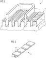
- Figure 1 shows a part of a generator 1 with a stator 2.
- the stator 2 has a cylindrical shape. The diameter depends of the application of the generator 1 and can reach several meters for example for a wind turbine application.
- Stator slots 3 are arranged at an outer or radial surface of the stator 2.
- stator slots 3 extend in an axial direction.
- the stator slots 3 accommodate preformed windings 4.
- a stator tooth 5 is arranged between two neighbouring stator slots 3 .
- the stator tooth 5 defines side walls of the openings of the neighbouring stator slots 3. Hence, stator slots 3 and stator teeth 5 are arranged alternately.
- a wedge 6 is attached to the stator 2 in order to retain the windings 4 inside the stator slots 3.
- the wedge 6 comprises a retaining portion 7, a length of which extends in axial direction.
- a width of the retaining portion 7 is such that it covers half of each of the two neighbouring stator slots 3.
- a mounting projection 8 is arranged and extends in axial direction.
- the mounting projection 8 is utilized for mounting the wedge 6 to a top or radial surface of a stator tooth 5.
- a corresponding recess 9 is provided.
- the mounting projection 8 and the recess 9 form a so called dovetail connection.
- the mounting projection 8 has an upper bar running in radial direction and a lower triangular portion.
- the recess 9 has the same form so that the mounting projection 8 fits into it. This connection allows mounting of the wedge 6 in axial direction but prevents displacement of the wedge 6 in radial direction. Other suitable connections fulfilling these requirements can be used as well.
- the wedge 6 and also the stator 2 consist of magnetic material preferably ferromagnetic material. This allows good electro-magnetic and mechanical characteristics.
- the wedge 6 and also the stator 2 are laminated to limit eddy currents inside the material. Thin slices or sections 10 of the wedge 6 and the stator 2 respectively are put together to form the wedge 6 and the stator 2 respectively. Face sides of the slices or sections 10 have their surfaces treated to insulate electrically two neighbouring slices or sections 10. To enhance stability the slides or sections 10 are glued together.
- stator 2 In the following the assembly of the stator 2 is described. First, the preformed windings 4 are inserted into the stator slots 3. This is done in radial direction. Then the wedges 6 are inserted into the recesses 9 in an axial fashion. Finally a VPI process (Vacuum Pressure Impregnation) may be done in which gaps between the wedge 6 and the recesses 9 provided in the stator teeth 5 will be filled up by resin and the wedge 6 will be stiffened in its place.
- VPI process Vauum Pressure Impregnation
- the material and arrangement of the wedges 6 optimizes the electro-magnetic properties of the generator 1 and thereby reduces vibration and noise.
- the coolant air is blown through the air gap and above the stator teeth 5 and wedge 6 so that the windings 4 are cooled efficiently.
- Figure 2 shows a wedge 6 prior to assembly.
- the sections 10 of the wedge 6 are not connected yet.
- face side 11 is covered with electrically insulating material or film as indicated by the hatching of the face side 11.
- the sections 10 are glued together to form a solid wedge 6.
- the actual thickness of a section 10 may be much smaller than depicted.
- Figure 3 shows an inventive implementation of the electrical insulation of the single sections 10 of the wedge 6.
- a spacer 12 is provided between the wedge laminations or sections 10 to insulate them from each other by the provided air gap distance. This can be used as an alternative to surface treatment.
- the spacer 12 can be a convex part of the face side 11 of the section 10.
- Figure 4 shows an implementation of the wedge 6 which minimizes ripple and cogging torque and thereby noise and fatigue. This is achieved by particularly formed edges and/or corners of the retaining portion 7. They comprise structures 13 which are optimized for electro-magnetic fields. The arrangement of the wedge 6 on a top surface of the stator tooth 5 gives ample freedom to design an optimal shape of the wedge 6.
Landscapes
- Engineering & Computer Science (AREA)
- Power Engineering (AREA)
- Insulation, Fastening Of Motor, Generator Windings (AREA)
- Iron Core Of Rotating Electric Machines (AREA)
Description
- The invention is directed to a wedge for a stator of a generator with preformed coil windings, a stator and a generator.
- In a typical stator of a generator with preformed coil windings a wedge is used to keep the coils fixed inside their respective stator slots. In wind power applications, preformed coils are preferred to other alternatives due to their high reliability. Because of their solid preformed structure, these coils need to be inserted radially into the slots. Therefore, the slots need to be completely open near the air gap. The wedge can be made of magnetic or non-magnetic material, while the non-magnetic wedge is preferred due to its higher reliability.
- To insert the wedge above the coils and close the open slots, the stator laminations have recesses inside the stator slots near the slot opening. It can be theoretically shown that these openings, in case of a non-magnetic wedge, increase the cogging and ripple torque due to magnetic saturation of the narrow corners of the stator teeth. Furthermore, in case the non-magnetic wedge is used, the wedge material has a low thermal conductivity and thereby insulates the winding from the airflow in the air gap and decreases the cooling efficiency of the generator. Finally, in case of non-magnetic wedge, the ripple and cogging torque can be significantly large which requires some ripple torque minimization techniques like shaping the permanent magnets in a permanent magnet generator.
-
US 3,641,378 A discloses an arrangement for securing stator windings with wedge shaped pieces. The pieces hold the windings at tapered sides thereof and leave a central portion of the winding's surface exposed. This enables a small distance between the windings or conductor bars and a rotor. -
JP 58 028550 U -
GB 619,058 -
US 2,290,487 describes wedges having a central longitudinal member of extruded metal such as aluminum or an alloy of high thermal conductivity. -
US 2,015,554 describes a laminated dynamo-electric machine made of a laminate and laminated wedges for closing slots in the dynamo-electric machine. -
DE 29 05 965 A1 describes wedges for closing stator slots which are spaced apart from each other and fixed in place by means of shims. -
DE 2 218 266 describes wedges for closing stator slots with longitudinal slots in some of the wedges. - It is an object of the invention to improve the isolating properties of wedges in a generator.
- This object is solved according to the invention with the features of
claims - In one aspect the invention is directed to a wedge for a stator of a generator with preformed coil windings, comprising a retaining portion for retaining coil windings, wherein the retaining portion covers at least part of two neighbouring stator slots, and a mounting projection at a bottom surface of the retaining portion for mounting the wedge to a top surface of a stator tooth located between the two neighbouring stator slots. The wedge is attached to a top or radial surface of the stator which allows more freedom in the mechanical and electro-magnetic design of the wedge. Furthermore, the cooling of the generator may be enhanced for forced air cooling generators. The ease of the insertion of the preformed coils into the open stator slots is combined with an easy to mount wedge. Accordingly only one pair of projection/recess is necessary to mount the wedge and therewith attach the coils in an easy and secure fashion.
- The retaining portion covers half of each of the two neighbouring stator slots. This size of the retaining portion allows easy handling and secure attachment of the coils.
- The wedge comprises several sections in a longitudinal direction, wherein the sections are spaced apart from each other by a spacer to insulate them from each other by the provided air gap distance. The spacer can be integrally formed with the wedge section, for example as part of a face side.
- The wedge may comprise ferromagnetic material. The proposed wedge is a better alternative than a conventional non-magnetic wedge and also than a conventional magnetic wedge. It keeps the ease of the insertion of the preformed coils into the open slots, while removing the disadvantage of having magnetically open slots by adding a magnetic wedge. This decreases the cogging and ripple torque. Further, the edge's or corner's shape of the wedge can be flexibly designed to minimize the vibration and noise, more easily and more effectively compared to a conventional magnetic wedge. Furthermore, for air cooled generators, the coolant air is blown through the air gap and above the stator teeth and wedge. In case of conventional non magnetic wedge, the wedge thermally insulates the underlying coil from the coolant air and thereby reduces the cooling efficiency. Here, the windings are cooled efficiently.
- The wedge may be laminated to limit the eddy currents in the wedge. It is further possible to glue the laminations together to form a solid structure. The thickness of the laminations can preferably be the same as stator laminations.
- Edges of the retaining portion may comprise a structure optimized for electromagnetic fields. The cogging and ripple torque and thereby noise and fatigue can be minimized using an optimal shape of the edges or corners of the wedge.
- The retaining portion may have a curved upper surface. The curved upper or radial surface can be adapted to the surface of the stator to enhance running smoothness.
- In a second aspect the invention is directed to a stator of a generator with preformed coil windings, comprising stator slots and stator teeth, wherein one stator tooth is arranged between two neighbouring stator slots, and a wedge as described above. The stator has the same advantages and modifications as the previously described wedge.
- A recess may be provided in a top surface of a stator tooth. The recess in a top or radial surface can be manufactured easily. Further, only one recess per wedge is necessary.
- The stator and the wedge may comprise the same ferromagnetic material. This decreases the cogging and ripple torque and thereby noise and fatigue can be minimized.
- The stator and the wedge may comprise the same laminated structure. This limits eddy currents in the stator and the wedge effectively.
- In a further aspect the invention is directed to a generator with preformed coil windings comprising a stator as described above. The generator has the same advantages and modifications as the previously described stator and/or wedge.
- The accompanying drawings are included to provide a further understanding of embodiments. Other embodiments and many of the intended advantages will be readily appreciated as they become better understood by reference to the following detailed description. The elements of the drawings do not necessarily scale to each other. Like reference numbers designate corresponding similar parts.
-
Fig. 1 illustrates a schematic perspective view of a wedge and part of the stator. -
Fig. 2 illustrates a schematic perspective view of a wedge. -
Fig. 3 illustrates a schematic side view of a wedge according to the invention. -
Fig. 4 illustrates a front view of a wedge. - In the following detailed description, reference is made to the accompanying drawings which form a part hereof and in which are shown by way of illustration specific embodiments in which the invention may be practised. In this regard, directional terminology, such as "top" or "bottom" etc. is used with reference to the orientation of the Figure(s) being described. Because components of embodiments can be positioned in a number of different orientations, the directional terminology is used for purposes of illustration and is in no way limiting. It is to be understood that other embodiments may be utilized.
- The following detailed description, therefore, is not to be taken in a limiting sense, and the scope of the present invention is defined by the appended claims.
-
Figure 1 shows a part of a generator 1 with a stator 2. The stator 2 has a cylindrical shape. The diameter depends of the application of the generator 1 and can reach several meters for example for a wind turbine application. Stator slots 3 are arranged at an outer or radial surface of the stator 2. - The stator slots 3 extend in an axial direction. The stator slots 3 accommodate preformed
windings 4. Between two neighbouring stator slots 3 a stator tooth 5 is arranged. The stator tooth 5 defines side walls of the openings of the neighbouring stator slots 3. Hence, stator slots 3 and stator teeth 5 are arranged alternately. - A
wedge 6 is attached to the stator 2 in order to retain thewindings 4 inside the stator slots 3. Thewedge 6 comprises a retainingportion 7, a length of which extends in axial direction. A width of the retainingportion 7 is such that it covers half of each of the two neighbouring stator slots 3. - For the sake of simplicity only one
wedge 6 is shown. Twowedges 6 located next to each other cover the intermediate stator slot 3 completely. The twowedges 6 can either fit closely or leave a gap in between. The retainingportions 7 should project far enough into the stator slots 3 to secure thewindings 4 inside the slots 3. - At a bottom or radial inner side of the retaining portion 7 a mounting
projection 8 is arranged and extends in axial direction. The mountingprojection 8 is utilized for mounting thewedge 6 to a top or radial surface of a stator tooth 5. There, a corresponding recess 9 is provided. During fabrication of the stator 2 the recesses 9 can for example be punched out. The mountingprojection 8 and the recess 9 form a so called dovetail connection. In this configuration the mountingprojection 8 has an upper bar running in radial direction and a lower triangular portion. The recess 9 has the same form so that the mountingprojection 8 fits into it. This connection allows mounting of thewedge 6 in axial direction but prevents displacement of thewedge 6 in radial direction. Other suitable connections fulfilling these requirements can be used as well. - The
wedge 6 and also the stator 2 consist of magnetic material preferably ferromagnetic material. This allows good electro-magnetic and mechanical characteristics. Thewedge 6 and also the stator 2 are laminated to limit eddy currents inside the material. Thin slices orsections 10 of thewedge 6 and the stator 2 respectively are put together to form thewedge 6 and the stator 2 respectively. Face sides of the slices orsections 10 have their surfaces treated to insulate electrically two neighbouring slices orsections 10. To enhance stability the slides orsections 10 are glued together. - In the following the assembly of the stator 2 is described. First, the preformed
windings 4 are inserted into the stator slots 3. This is done in radial direction. Then thewedges 6 are inserted into the recesses 9 in an axial fashion. Finally a VPI process (Vacuum Pressure Impregnation) may be done in which gaps between thewedge 6 and the recesses 9 provided in the stator teeth 5 will be filled up by resin and thewedge 6 will be stiffened in its place. - During operation of the generator 1 the material and arrangement of the
wedges 6 optimizes the electro-magnetic properties of the generator 1 and thereby reduces vibration and noise. For air cooled generators, the coolant air is blown through the air gap and above the stator teeth 5 andwedge 6 so that thewindings 4 are cooled efficiently. -
Figure 2 shows awedge 6 prior to assembly. Thesections 10 of thewedge 6 are not connected yet. In an embodiment which is not part of the present invention, faceside 11 is covered with electrically insulating material or film as indicated by the hatching of theface side 11. In the next step thesections 10 are glued together to form asolid wedge 6. The actual thickness of asection 10 may be much smaller than depicted. -
Figure 3 shows an inventive implementation of the electrical insulation of thesingle sections 10 of thewedge 6. Here, aspacer 12 is provided between the wedge laminations orsections 10 to insulate them from each other by the provided air gap distance. This can be used as an alternative to surface treatment. Thespacer 12 can be a convex part of theface side 11 of thesection 10. -
Figure 4 shows an implementation of thewedge 6 which minimizes ripple and cogging torque and thereby noise and fatigue. This is achieved by particularly formed edges and/or corners of the retainingportion 7. They comprisestructures 13 which are optimized for electro-magnetic fields. The arrangement of thewedge 6 on a top surface of the stator tooth 5 gives ample freedom to design an optimal shape of thewedge 6.
Claims (10)
- Wedge for a stator (2) of a generator (1) with preformed coil windings (4), comprising a retaining portion (7) for retaining coil windings (4), wherein the retaining portion (7) covers at least part of two neighbouring stator slots (3), and a mounting projection (8) at a bottom surface of the retaining portion (7) for mounting the wedge (6) to a top surface of a stator tooth (5) located between the two neighbouring stator slots (3),
characterised in that
the retaining portion (7) covers half of each of the two neighbouring stator slots (3), and
the wedge comprises several sections (10) in a longitudinal direction, wherein the sections (10) are spaced apart from each other by a spacer (12) to isolate them from each other by a provided air gap distance. - Wedge for a stator (2) according to claim 1, wherein the wedge (6) comprises ferromagnetic material.
- Wedge for a stator (2) according to claim 1 or 2, wherein the wedge (6) is laminated.
- Wedge for a stator (2) according to one of claims 1 to 3, wherein edges of the retaining portion (7) comprise a structure (13) optimized for electromagnetic fields.
- Wedge for a stator (2) according to one of claims 1 to 4, wherein the retaining portion (7) has a curved upper surface.
- Stator of a generator (1) with preformed coil windings (4), comprising stator slots (3) and stator teeth (5), wherein one stator tooth (5) is arranged between two neighbouring stator slots (3), and a wedge (6) according to one of claims 1 to 5.
- Stator of a generator (1) according to claim 6, wherein a recess (9) is provided in a top surface of a stator tooth (5).
- Stator of a generator (1) according to claim 6 or 7, wherein the stator (2) and the wedge (6) comprises the same ferromagnetic material.
- Stator of a generator (1) according to one of claims 6 to 8, wherein the stator (2) and the wedge (6) comprise the same laminated structure.
- Generator with preformed coil windings (4) comprising a stator (2) according to one of claims 6 to 9.
Priority Applications (4)
| Application Number | Priority Date | Filing Date | Title |
|---|---|---|---|
| EP10192754.9A EP2458714B1 (en) | 2010-11-26 | 2010-11-26 | Wedge for a stator of a generator with preformed coil windings |
| US13/293,175 US8618710B2 (en) | 2010-11-26 | 2011-11-10 | Wedge for a stator of a generator with preformed coil windings |
| CA2759499A CA2759499C (en) | 2010-11-26 | 2011-11-24 | Wedge for a stator of a generator with preformed coil windings |
| CN201110380427.5A CN102570676B (en) | 2010-11-26 | 2011-11-25 | Slot wedge for the stator of the generator with prefabricated coil winding |
Applications Claiming Priority (1)
| Application Number | Priority Date | Filing Date | Title |
|---|---|---|---|
| EP10192754.9A EP2458714B1 (en) | 2010-11-26 | 2010-11-26 | Wedge for a stator of a generator with preformed coil windings |
Publications (2)
| Publication Number | Publication Date |
|---|---|
| EP2458714A1 EP2458714A1 (en) | 2012-05-30 |
| EP2458714B1 true EP2458714B1 (en) | 2017-03-22 |
Family
ID=44063733
Family Applications (1)
| Application Number | Title | Priority Date | Filing Date |
|---|---|---|---|
| EP10192754.9A Not-in-force EP2458714B1 (en) | 2010-11-26 | 2010-11-26 | Wedge for a stator of a generator with preformed coil windings |
Country Status (4)
| Country | Link |
|---|---|
| US (1) | US8618710B2 (en) |
| EP (1) | EP2458714B1 (en) |
| CN (1) | CN102570676B (en) |
| CA (1) | CA2759499C (en) |
Cited By (1)
| Publication number | Priority date | Publication date | Assignee | Title |
|---|---|---|---|---|
| US11489396B2 (en) | 2018-11-15 | 2022-11-01 | Black 7 Decker Inc. | Winding retention insert for a brushless motor |
Families Citing this family (12)
| Publication number | Priority date | Publication date | Assignee | Title |
|---|---|---|---|---|
| US8853911B2 (en) * | 2012-09-28 | 2014-10-07 | Hamilton Sundstrand Corporation | Generator/motor wedge with lamination interface for reduced stress levels |
| EP2947752A1 (en) | 2014-05-19 | 2015-11-25 | ALSTOM Renewable Technologies | Wedge mechanism |
| CN104821677B (en) * | 2015-05-14 | 2018-08-17 | 北京交通大学 | The stator major-minor slot wedge of large turbo-type generator |
| CN105703496A (en) * | 2016-04-13 | 2016-06-22 | 阮自恒 | Improvement of motor iron slot |
| CN107659019A (en) * | 2017-08-18 | 2018-02-02 | 河北电机股份有限公司 | A kind of high-voltage motor for being easy to regulation motor Magnetic circuit characters |
| US11081920B2 (en) * | 2017-09-29 | 2021-08-03 | Hamilton Sundstrand Corporation | Rotor wedges and layers and heat sinks |
| CN107979203A (en) * | 2017-12-27 | 2018-05-01 | 新疆金风科技股份有限公司 | Slot wedge, Stator and electrical machine and the method for manufacturing the slot wedge |
| CN109617286A (en) * | 2018-12-12 | 2019-04-12 | 陕西航空电气有限责任公司 | The implementation method of pump motor insulation performance under alkaline conduction coolant liquid working media |
| EP4102682A1 (en) * | 2021-06-09 | 2022-12-14 | Siemens Gamesa Renewable Energy A/S | Generator, wind turbine and method for cooling a direct drive generator of a wind turbine |
| CN113890243B (en) * | 2021-09-16 | 2023-01-06 | 华中科技大学 | A hairpin structure soft magnetic composite material magnetic slot wedge |
| ES3064098T3 (en) | 2021-10-22 | 2026-04-22 | Ge Vernova Renovables Espana S L | Electrical machine tooth assemblies and methods |
| DE102024125652A1 (en) * | 2024-09-06 | 2026-03-12 | Valeo Eautomotive Germany Gmbh | Stator for an electric machine with an improved radial mounting option for a stator winding, as well as an electric machine, vehicle and related manufacturing processes. |
Citations (2)
| Publication number | Priority date | Publication date | Assignee | Title |
|---|---|---|---|---|
| DE2218266A1 (en) * | 1971-04-26 | 1972-11-09 | Westinghouse Electric Corp., Pittsburgh, Pa. (V.St.A.) | Electric machine |
| DE2905965A1 (en) * | 1979-02-13 | 1980-08-21 | Siemens Ag | Electric machine slot closing wedge retainer - is made of resin impregnated glass mat insert subject to swelling and hardening |
Family Cites Families (15)
| Publication number | Priority date | Publication date | Assignee | Title |
|---|---|---|---|---|
| US2015554A (en) * | 1933-12-08 | 1935-09-24 | Gen Electric | Magnetic wedge |
| GB619058A (en) * | 1946-06-11 | 1949-03-03 | Edward Woosey | Improvements relating to dynamo electric machines |
| US2990487A (en) * | 1957-11-15 | 1961-06-27 | Gen Motors Corp | Method and wedges for conducting heat from slots of dynamoelectric machine |
| FR2044959A5 (en) * | 1969-05-28 | 1971-02-26 | Cem Comp Electro Mec | |
| JPS5828550A (en) | 1981-07-28 | 1983-02-19 | Toyota Motor Corp | Electronically controlled fuel injector for multicylinder internal combustion engine with auxiliary intake passages |
| JPS5828550U (en) * | 1981-08-20 | 1983-02-24 | 株式会社東芝 | rotating electric machine |
| DE3612819A1 (en) * | 1986-04-16 | 1987-10-22 | Siemens Ag | ARRANGEMENT FOR FASTENING AN AIR GAP WINDING AND METHOD FOR ASSEMBLING AND DISASSEMBLING IT |
| US5239220A (en) * | 1990-04-26 | 1993-08-24 | Mitsubishi Denki K.K. | Stator wedge and guide jig therefor |
| US5252877A (en) * | 1990-06-29 | 1993-10-12 | Kabushiki Kaisha Toshiba | Slot insulating magnetic wedges |
| US5258681A (en) * | 1990-06-29 | 1993-11-02 | Kabushiki Kaisha Toshiba | Magnetic slot wedges for dynamo-electric machines |
| US5365135A (en) * | 1993-11-12 | 1994-11-15 | Westinghouse Electric Corporation | Generator slot hose wedge assembly |
| CN1281281A (en) * | 1999-07-19 | 2001-01-24 | 陈启星 | Electric machine with magnetic cover on slot |
| US6453545B1 (en) * | 2000-12-06 | 2002-09-24 | General Electric Company | Compact inflatable device for applying localized pressure to turbine generator armature bars |
| CN2938538Y (en) * | 2006-03-07 | 2007-08-22 | 江苏富天江电子电器有限公司 | Isolation stator |
| CN102684330A (en) * | 2012-05-10 | 2012-09-19 | 罗子航 | Stator of inner-rotor motor with outward rabbet, and mating housing |
-
2010
- 2010-11-26 EP EP10192754.9A patent/EP2458714B1/en not_active Not-in-force
-
2011
- 2011-11-10 US US13/293,175 patent/US8618710B2/en not_active Expired - Fee Related
- 2011-11-24 CA CA2759499A patent/CA2759499C/en active Active
- 2011-11-25 CN CN201110380427.5A patent/CN102570676B/en not_active Expired - Fee Related
Patent Citations (2)
| Publication number | Priority date | Publication date | Assignee | Title |
|---|---|---|---|---|
| DE2218266A1 (en) * | 1971-04-26 | 1972-11-09 | Westinghouse Electric Corp., Pittsburgh, Pa. (V.St.A.) | Electric machine |
| DE2905965A1 (en) * | 1979-02-13 | 1980-08-21 | Siemens Ag | Electric machine slot closing wedge retainer - is made of resin impregnated glass mat insert subject to swelling and hardening |
Cited By (1)
| Publication number | Priority date | Publication date | Assignee | Title |
|---|---|---|---|---|
| US11489396B2 (en) | 2018-11-15 | 2022-11-01 | Black 7 Decker Inc. | Winding retention insert for a brushless motor |
Also Published As
| Publication number | Publication date |
|---|---|
| US8618710B2 (en) | 2013-12-31 |
| CA2759499C (en) | 2018-10-16 |
| CN102570676B (en) | 2017-08-15 |
| EP2458714A1 (en) | 2012-05-30 |
| CA2759499A1 (en) | 2012-05-26 |
| CN102570676A (en) | 2012-07-11 |
| US20120133237A1 (en) | 2012-05-31 |
Similar Documents
| Publication | Publication Date | Title |
|---|---|---|
| CA2759499C (en) | Wedge for a stator of a generator with preformed coil windings | |
| KR101911978B1 (en) | Spoke permanent magnet machine with reduced torque ripple and method of manufacturing thereof | |
| EP2951907B1 (en) | Pole shoe cooling gap for axial motor | |
| CN103597714B (en) | The manufacture method of rotor for dynamo-electric machine, electric rotating machine and rotor for dynamo-electric machine | |
| CN102439822B (en) | A permanent magnet module for an electrical machine | |
| US8749103B2 (en) | Permanent magnet rotor for electric machine | |
| EP4287473A1 (en) | Stator for axial-flux electric machine | |
| EP1865587B1 (en) | Magnetic powder metal composite core for electrical machines | |
| CN103378663B (en) | Pole shoe structure for the machine parts of motor | |
| JP6832935B2 (en) | Consequential pole type rotor, electric motor and air conditioner | |
| US7952237B2 (en) | Primary part having a cover for a linear motor | |
| KR20110103955A (en) | Method for manufacturing electric machine and its stator part | |
| EP2854256B1 (en) | Pole unit and stator assembly for a wind turbine generator, and methods of manufacturing the same | |
| GB2511421A (en) | Electrical machines | |
| US20210218294A1 (en) | Stator for a rotating electrical machine | |
| JP4197584B2 (en) | Method for manufacturing rotor of permanent magnet type rotating electric machine | |
| WO2005057755A1 (en) | Polyphase claw-pole machines with a segmented magnetic circuit | |
| JP2009506744A (en) | Apparatus and method for clamping and locking a permanent magnet and improving cooling in rotating electrical equipment | |
| WO2019116389A1 (en) | Unitary stator, slit rotor and a switched reluctance device thereof | |
| WO2005060073A1 (en) | Hybrid construction electric machine | |
| KR20120010993A (en) | Electric motor in the form of split armature | |
| US20250192636A1 (en) | A bobbin | |
| JP2021522767A (en) | Rotor for rotating electromechanical | |
| WO2008107512A1 (en) | Pole module for rotor of electric machine and rotor of electric machine | |
| JPH11103548A (en) | Permanent magnet type rotor with braking winding |
Legal Events
| Date | Code | Title | Description |
|---|---|---|---|
| PUAI | Public reference made under article 153(3) epc to a published international application that has entered the european phase |
Free format text: ORIGINAL CODE: 0009012 |
|
| AK | Designated contracting states |
Kind code of ref document: A1 Designated state(s): AL AT BE BG CH CY CZ DE DK EE ES FI FR GB GR HR HU IE IS IT LI LT LU LV MC MK MT NL NO PL PT RO RS SE SI SK SM TR |
|
| AX | Request for extension of the european patent |
Extension state: BA ME |
|
| 17P | Request for examination filed |
Effective date: 20120709 |
|
| 17Q | First examination report despatched |
Effective date: 20130123 |
|
| RAP1 | Party data changed (applicant data changed or rights of an application transferred) |
Owner name: SIEMENS AKTIENGESELLSCHAFT |
|
| GRAP | Despatch of communication of intention to grant a patent |
Free format text: ORIGINAL CODE: EPIDOSNIGR1 |
|
| RIC1 | Information provided on ipc code assigned before grant |
Ipc: H02K 3/487 20060101AFI20160915BHEP Ipc: H02K 3/493 20060101ALI20160915BHEP |
|
| INTG | Intention to grant announced |
Effective date: 20161007 |
|
| GRAS | Grant fee paid |
Free format text: ORIGINAL CODE: EPIDOSNIGR3 |
|
| GRAA | (expected) grant |
Free format text: ORIGINAL CODE: 0009210 |
|
| AK | Designated contracting states |
Kind code of ref document: B1 Designated state(s): AL AT BE BG CH CY CZ DE DK EE ES FI FR GB GR HR HU IE IS IT LI LT LU LV MC MK MT NL NO PL PT RO RS SE SI SK SM TR |
|
| REG | Reference to a national code |
Ref country code: GB Ref legal event code: FG4D |
|
| REG | Reference to a national code |
Ref country code: CH Ref legal event code: EP |
|
| REG | Reference to a national code |
Ref country code: AT Ref legal event code: REF Ref document number: 878640 Country of ref document: AT Kind code of ref document: T Effective date: 20170415 |
|
| REG | Reference to a national code |
Ref country code: IE Ref legal event code: FG4D |
|
| REG | Reference to a national code |
Ref country code: DE Ref legal event code: R096 Ref document number: 602010040905 Country of ref document: DE |
|
| REG | Reference to a national code |
Ref country code: NL Ref legal event code: MP Effective date: 20170322 |
|
| PG25 | Lapsed in a contracting state [announced via postgrant information from national office to epo] |
Ref country code: LT Free format text: LAPSE BECAUSE OF FAILURE TO SUBMIT A TRANSLATION OF THE DESCRIPTION OR TO PAY THE FEE WITHIN THE PRESCRIBED TIME-LIMIT Effective date: 20170322 Ref country code: HR Free format text: LAPSE BECAUSE OF FAILURE TO SUBMIT A TRANSLATION OF THE DESCRIPTION OR TO PAY THE FEE WITHIN THE PRESCRIBED TIME-LIMIT Effective date: 20170322 Ref country code: NO Free format text: LAPSE BECAUSE OF FAILURE TO SUBMIT A TRANSLATION OF THE DESCRIPTION OR TO PAY THE FEE WITHIN THE PRESCRIBED TIME-LIMIT Effective date: 20170622 Ref country code: FI Free format text: LAPSE BECAUSE OF FAILURE TO SUBMIT A TRANSLATION OF THE DESCRIPTION OR TO PAY THE FEE WITHIN THE PRESCRIBED TIME-LIMIT Effective date: 20170322 Ref country code: GR Free format text: LAPSE BECAUSE OF FAILURE TO SUBMIT A TRANSLATION OF THE DESCRIPTION OR TO PAY THE FEE WITHIN THE PRESCRIBED TIME-LIMIT Effective date: 20170623 |
|
| REG | Reference to a national code |
Ref country code: LT Ref legal event code: MG4D |
|
| REG | Reference to a national code |
Ref country code: AT Ref legal event code: MK05 Ref document number: 878640 Country of ref document: AT Kind code of ref document: T Effective date: 20170322 |
|
| RAP2 | Party data changed (patent owner data changed or rights of a patent transferred) |
Owner name: SIEMENS AKTIENGESELLSCHAFT |
|
| PG25 | Lapsed in a contracting state [announced via postgrant information from national office to epo] |
Ref country code: SE Free format text: LAPSE BECAUSE OF FAILURE TO SUBMIT A TRANSLATION OF THE DESCRIPTION OR TO PAY THE FEE WITHIN THE PRESCRIBED TIME-LIMIT Effective date: 20170322 Ref country code: RS Free format text: LAPSE BECAUSE OF FAILURE TO SUBMIT A TRANSLATION OF THE DESCRIPTION OR TO PAY THE FEE WITHIN THE PRESCRIBED TIME-LIMIT Effective date: 20170322 Ref country code: BG Free format text: LAPSE BECAUSE OF FAILURE TO SUBMIT A TRANSLATION OF THE DESCRIPTION OR TO PAY THE FEE WITHIN THE PRESCRIBED TIME-LIMIT Effective date: 20170622 Ref country code: LV Free format text: LAPSE BECAUSE OF FAILURE TO SUBMIT A TRANSLATION OF THE DESCRIPTION OR TO PAY THE FEE WITHIN THE PRESCRIBED TIME-LIMIT Effective date: 20170322 |
|
| PG25 | Lapsed in a contracting state [announced via postgrant information from national office to epo] |
Ref country code: NL Free format text: LAPSE BECAUSE OF FAILURE TO SUBMIT A TRANSLATION OF THE DESCRIPTION OR TO PAY THE FEE WITHIN THE PRESCRIBED TIME-LIMIT Effective date: 20170322 |
|
| REG | Reference to a national code |
Ref country code: CH Ref legal event code: NV Representative=s name: SIEMENS SCHWEIZ AG, CH Ref country code: CH Ref legal event code: PCOW Free format text: NEW ADDRESS: WERNER-VON-SIEMENS-STRASSE 1, 80333 MUENCHEN (DE) |
|
| PG25 | Lapsed in a contracting state [announced via postgrant information from national office to epo] |
Ref country code: AT Free format text: LAPSE BECAUSE OF FAILURE TO SUBMIT A TRANSLATION OF THE DESCRIPTION OR TO PAY THE FEE WITHIN THE PRESCRIBED TIME-LIMIT Effective date: 20170322 Ref country code: RO Free format text: LAPSE BECAUSE OF FAILURE TO SUBMIT A TRANSLATION OF THE DESCRIPTION OR TO PAY THE FEE WITHIN THE PRESCRIBED TIME-LIMIT Effective date: 20170322 Ref country code: EE Free format text: LAPSE BECAUSE OF FAILURE TO SUBMIT A TRANSLATION OF THE DESCRIPTION OR TO PAY THE FEE WITHIN THE PRESCRIBED TIME-LIMIT Effective date: 20170322 Ref country code: IT Free format text: LAPSE BECAUSE OF FAILURE TO SUBMIT A TRANSLATION OF THE DESCRIPTION OR TO PAY THE FEE WITHIN THE PRESCRIBED TIME-LIMIT Effective date: 20170322 Ref country code: SK Free format text: LAPSE BECAUSE OF FAILURE TO SUBMIT A TRANSLATION OF THE DESCRIPTION OR TO PAY THE FEE WITHIN THE PRESCRIBED TIME-LIMIT Effective date: 20170322 Ref country code: ES Free format text: LAPSE BECAUSE OF FAILURE TO SUBMIT A TRANSLATION OF THE DESCRIPTION OR TO PAY THE FEE WITHIN THE PRESCRIBED TIME-LIMIT Effective date: 20170322 Ref country code: CZ Free format text: LAPSE BECAUSE OF FAILURE TO SUBMIT A TRANSLATION OF THE DESCRIPTION OR TO PAY THE FEE WITHIN THE PRESCRIBED TIME-LIMIT Effective date: 20170322 |
|
| PG25 | Lapsed in a contracting state [announced via postgrant information from national office to epo] |
Ref country code: SM Free format text: LAPSE BECAUSE OF FAILURE TO SUBMIT A TRANSLATION OF THE DESCRIPTION OR TO PAY THE FEE WITHIN THE PRESCRIBED TIME-LIMIT Effective date: 20170322 Ref country code: PL Free format text: LAPSE BECAUSE OF FAILURE TO SUBMIT A TRANSLATION OF THE DESCRIPTION OR TO PAY THE FEE WITHIN THE PRESCRIBED TIME-LIMIT Effective date: 20170322 Ref country code: PT Free format text: LAPSE BECAUSE OF FAILURE TO SUBMIT A TRANSLATION OF THE DESCRIPTION OR TO PAY THE FEE WITHIN THE PRESCRIBED TIME-LIMIT Effective date: 20170724 Ref country code: IS Free format text: LAPSE BECAUSE OF FAILURE TO SUBMIT A TRANSLATION OF THE DESCRIPTION OR TO PAY THE FEE WITHIN THE PRESCRIBED TIME-LIMIT Effective date: 20170722 |
|
| REG | Reference to a national code |
Ref country code: DE Ref legal event code: R097 Ref document number: 602010040905 Country of ref document: DE |
|
| PLBE | No opposition filed within time limit |
Free format text: ORIGINAL CODE: 0009261 |
|
| STAA | Information on the status of an ep patent application or granted ep patent |
Free format text: STATUS: NO OPPOSITION FILED WITHIN TIME LIMIT |
|
| PG25 | Lapsed in a contracting state [announced via postgrant information from national office to epo] |
Ref country code: DK Free format text: LAPSE BECAUSE OF FAILURE TO SUBMIT A TRANSLATION OF THE DESCRIPTION OR TO PAY THE FEE WITHIN THE PRESCRIBED TIME-LIMIT Effective date: 20170322 |
|
| 26N | No opposition filed |
Effective date: 20180102 |
|
| PG25 | Lapsed in a contracting state [announced via postgrant information from national office to epo] |
Ref country code: SI Free format text: LAPSE BECAUSE OF FAILURE TO SUBMIT A TRANSLATION OF THE DESCRIPTION OR TO PAY THE FEE WITHIN THE PRESCRIBED TIME-LIMIT Effective date: 20170322 |
|
| PG25 | Lapsed in a contracting state [announced via postgrant information from national office to epo] |
Ref country code: MC Free format text: LAPSE BECAUSE OF FAILURE TO SUBMIT A TRANSLATION OF THE DESCRIPTION OR TO PAY THE FEE WITHIN THE PRESCRIBED TIME-LIMIT Effective date: 20170322 |
|
| PG25 | Lapsed in a contracting state [announced via postgrant information from national office to epo] |
Ref country code: LI Free format text: LAPSE BECAUSE OF NON-PAYMENT OF DUE FEES Effective date: 20171130 Ref country code: CH Free format text: LAPSE BECAUSE OF NON-PAYMENT OF DUE FEES Effective date: 20171130 |
|
| PG25 | Lapsed in a contracting state [announced via postgrant information from national office to epo] |
Ref country code: LU Free format text: LAPSE BECAUSE OF NON-PAYMENT OF DUE FEES Effective date: 20171126 |
|
| REG | Reference to a national code |
Ref country code: FR Ref legal event code: ST Effective date: 20180731 Ref country code: BE Ref legal event code: MM Effective date: 20171130 |
|
| REG | Reference to a national code |
Ref country code: IE Ref legal event code: MM4A |
|
| PG25 | Lapsed in a contracting state [announced via postgrant information from national office to epo] |
Ref country code: MT Free format text: LAPSE BECAUSE OF NON-PAYMENT OF DUE FEES Effective date: 20171126 |
|
| PG25 | Lapsed in a contracting state [announced via postgrant information from national office to epo] |
Ref country code: FR Free format text: LAPSE BECAUSE OF NON-PAYMENT OF DUE FEES Effective date: 20171130 Ref country code: IE Free format text: LAPSE BECAUSE OF NON-PAYMENT OF DUE FEES Effective date: 20171126 |
|
| PG25 | Lapsed in a contracting state [announced via postgrant information from national office to epo] |
Ref country code: BE Free format text: LAPSE BECAUSE OF NON-PAYMENT OF DUE FEES Effective date: 20171130 |
|
| PG25 | Lapsed in a contracting state [announced via postgrant information from national office to epo] |
Ref country code: HU Free format text: LAPSE BECAUSE OF FAILURE TO SUBMIT A TRANSLATION OF THE DESCRIPTION OR TO PAY THE FEE WITHIN THE PRESCRIBED TIME-LIMIT; INVALID AB INITIO Effective date: 20101126 |
|
| REG | Reference to a national code |
Ref country code: DE Ref legal event code: R081 Ref document number: 602010040905 Country of ref document: DE Owner name: SIEMENS GAMESA RENEWABLE ENERGY A/S, DK Free format text: FORMER OWNER: SIEMENS AKTIENGESELLSCHAFT, 80333 MUENCHEN, DE |
|
| PG25 | Lapsed in a contracting state [announced via postgrant information from national office to epo] |
Ref country code: CY Free format text: LAPSE BECAUSE OF NON-PAYMENT OF DUE FEES Effective date: 20170322 |
|
| PG25 | Lapsed in a contracting state [announced via postgrant information from national office to epo] |
Ref country code: MK Free format text: LAPSE BECAUSE OF FAILURE TO SUBMIT A TRANSLATION OF THE DESCRIPTION OR TO PAY THE FEE WITHIN THE PRESCRIBED TIME-LIMIT Effective date: 20170322 |
|
| REG | Reference to a national code |
Ref country code: GB Ref legal event code: 732E Free format text: REGISTERED BETWEEN 20191128 AND 20191204 |
|
| PG25 | Lapsed in a contracting state [announced via postgrant information from national office to epo] |
Ref country code: TR Free format text: LAPSE BECAUSE OF FAILURE TO SUBMIT A TRANSLATION OF THE DESCRIPTION OR TO PAY THE FEE WITHIN THE PRESCRIBED TIME-LIMIT Effective date: 20170322 |
|
| PG25 | Lapsed in a contracting state [announced via postgrant information from national office to epo] |
Ref country code: AL Free format text: LAPSE BECAUSE OF FAILURE TO SUBMIT A TRANSLATION OF THE DESCRIPTION OR TO PAY THE FEE WITHIN THE PRESCRIBED TIME-LIMIT Effective date: 20170322 |
|
| PGFP | Annual fee paid to national office [announced via postgrant information from national office to epo] |
Ref country code: GB Payment date: 20221123 Year of fee payment: 13 Ref country code: DE Payment date: 20221121 Year of fee payment: 13 |
|
| REG | Reference to a national code |
Ref country code: DE Ref legal event code: R119 Ref document number: 602010040905 Country of ref document: DE |
|
| GBPC | Gb: european patent ceased through non-payment of renewal fee |
Effective date: 20231126 |
|
| PG25 | Lapsed in a contracting state [announced via postgrant information from national office to epo] |
Ref country code: DE Free format text: LAPSE BECAUSE OF NON-PAYMENT OF DUE FEES Effective date: 20240601 |
|
| PG25 | Lapsed in a contracting state [announced via postgrant information from national office to epo] |
Ref country code: GB Free format text: LAPSE BECAUSE OF NON-PAYMENT OF DUE FEES Effective date: 20231126 |
|
| PG25 | Lapsed in a contracting state [announced via postgrant information from national office to epo] |
Ref country code: GB Free format text: LAPSE BECAUSE OF NON-PAYMENT OF DUE FEES Effective date: 20231126 Ref country code: DE Free format text: LAPSE BECAUSE OF NON-PAYMENT OF DUE FEES Effective date: 20240601 |