EP2458287A1 - Control panel of a cooking appliance - Google Patents
Control panel of a cooking appliance Download PDFInfo
- Publication number
- EP2458287A1 EP2458287A1 EP11190818A EP11190818A EP2458287A1 EP 2458287 A1 EP2458287 A1 EP 2458287A1 EP 11190818 A EP11190818 A EP 11190818A EP 11190818 A EP11190818 A EP 11190818A EP 2458287 A1 EP2458287 A1 EP 2458287A1
- Authority
- EP
- European Patent Office
- Prior art keywords
- knob
- control panel
- cooking appliance
- illuminating element
- sensor
- Prior art date
- Legal status (The legal status is an assumption and is not a legal conclusion. Google has not performed a legal analysis and makes no representation as to the accuracy of the status listed.)
- Withdrawn
Links
- 238000010411 cooking Methods 0.000 title claims abstract description 16
- 230000005611 electricity Effects 0.000 claims abstract description 7
- 238000005286 illumination Methods 0.000 description 2
Images

Classifications
-
- G—PHYSICS
- G05—CONTROLLING; REGULATING
- G05G—CONTROL DEVICES OR SYSTEMS INSOFAR AS CHARACTERISED BY MECHANICAL FEATURES ONLY
- G05G1/00—Controlling members, e.g. knobs or handles; Assemblies or arrangements thereof; Indicating position of controlling members
- G05G1/08—Controlling members for hand actuation by rotary movement, e.g. hand wheels
-
- F—MECHANICAL ENGINEERING; LIGHTING; HEATING; WEAPONS; BLASTING
- F24—HEATING; RANGES; VENTILATING
- F24C—DOMESTIC STOVES OR RANGES ; DETAILS OF DOMESTIC STOVES OR RANGES, OF GENERAL APPLICATION
- F24C7/00—Stoves or ranges heated by electric energy
- F24C7/08—Arrangement or mounting of control or safety devices
- F24C7/082—Arrangement or mounting of control or safety devices on ranges, e.g. control panels, illumination
-
- H—ELECTRICITY
- H01—ELECTRIC ELEMENTS
- H01H—ELECTRIC SWITCHES; RELAYS; SELECTORS; EMERGENCY PROTECTIVE DEVICES
- H01H19/00—Switches operated by an operating part which is rotatable about a longitudinal axis thereof and which is acted upon directly by a solid body external to the switch, e.g. by a hand
- H01H19/02—Details
- H01H19/025—Light-emitting indicators
-
- H—ELECTRICITY
- H01—ELECTRIC ELEMENTS
- H01H—ELECTRIC SWITCHES; RELAYS; SELECTORS; EMERGENCY PROTECTIVE DEVICES
- H01H9/00—Details of switching devices, not covered by groups H01H1/00 - H01H7/00
- H01H9/16—Indicators for switching condition, e.g. "on" or "off"
- H01H9/161—Indicators for switching condition, e.g. "on" or "off" comprising light emitting elements
- H01H2009/164—Indicators for switching condition, e.g. "on" or "off" comprising light emitting elements the light emitting elements being incorporated in and movable with the operating part
-
- H—ELECTRICITY
- H01—ELECTRIC ELEMENTS
- H01H—ELECTRIC SWITCHES; RELAYS; SELECTORS; EMERGENCY PROTECTIVE DEVICES
- H01H36/00—Switches actuated by change of magnetic field or of electric field, e.g. by change of relative position of magnet and switch, by shielding
- H01H36/0006—Permanent magnet actuating reed switches
- H01H36/0033—Mountings; Housings; Connections
Definitions
- This invention relates to control panels, used in cooking appliances and comprising knobs to adjust the operation of heaters provided in said appliances.
- the cooking appliance control panel comprises at least one rotary control knob provided at the front thereof; and one adjustment bar for each knob, provided at the rear thereof, each of said bars coupled to an individual knob to adjust the operation of the respective heaters of the appliance.
- the panel further comprises a carrier member, fitted to the adjustment bar and provided with a magnetic element; and an electrical unit, provided with at least one magnetic sensor and illuminating element. The light emitted from this illuminating element is passed through the interior of the knob. When a magnetic element comes in front of the sensor with rotating the knob; the sensor interrupts the electricity supply to the illuminating element.
- the object of this invention is to provide a control panel, comprising rotary control knobs having also an illumination feature for cooking appliances.
- Another object of this invention is to provide an easily-producible and inexpensive, reliable machine, having the aforesaid features.
- FIG. 1 gives a perspective schematic view of a control panel (A) provided in a cooking appliance (not illustrated in figures) according to the present invention, which is presented in an assembled form.
- the cooking appliance control panel (A) here comprises at least one rotary control knob (3) and a front plate (1) just behind the knobs (3); and an equipment at the rear section (2), said equipment remaining behind the plate (1) and ensuring the adjustment of the functions of the cooking appliance. Between this equipment are provided components (not illustrated in figures), e.g. valves for gas cookers, potentiometers for electrical cookers, etc. and an electrical unit (7) with the following details.
- Said electrical unit (7) is illustrated in figures 1 and 2 , and is preferably made in the form of a printed circuit board, in terms of production and assembly easiness.
- the electrical unit (7) are provided at least one magnetic sensor (8) and illuminating element (9) (e.g. LED or bulb).
- This sensor (8) determines if light is to be emitted from the illuminating element (9).
- a magnetic element (6) see figures 1 and 3
- the sensor (8) interrupts the electricity supply to the illuminating element (9).
- the magnetic element (6) is moved away from the sensor (8) (i.e.
- FIG 3 is a perspective schematic view of the magnetic element (6) and carrier member (5) prior to assembly.
- the carrier member (5) is designed to place the magnetic element (6) thereon.
- the magnetic element (6) is placed into a socket (15) provided on the member (5), wherein this magnetic element (6) changes its position according to the movement of the carrier member (5).
- On the carrier member (5) is provided also a separate socket (14) for fitting the member (5) to the adjustment bar (4) (see Figure 1 ) (the adjustment bar (4) is introduced into this socket (14)).
- the adjustment bar (4) illustrated in Figure 1 is used to adjust the parts (i.e. gas or electrical heaters) such as a gas valve or a potentiometer of an electrical heater (not illustrated in figures).
- the rotary control knob (3) is fitted onto the adjustment bar (4), such that when the knob (3) is rotated, the adjustment bar (4) is rotated as well.
- the magnetic element (6) on the carrier member (5) fitted to the adjustment bar (4) also changes its position when the bar (4) is rotated.
- the illumination of the illuminating elements (9) is an indication that the gas cookers or electric heaters are in an operative state. It is ensured with this invention to deliver the light emitted from the illuminating elements (9) to a user via the rotary control knob (3), and to indicate that the respective functions are conducted in relation to that knob (3).
- the knob (3) structure illustrated in figures 1 and 4 are developed for this purpose.
- the rotary control knob (3) here is fitted to the adjustment bar (4) passed through the interior of the hole (10) on the front plate (1).
- the knob (3) comprises an opaque knob body (11) and a knob socket (13), as well as at least one transparent member (12), provided in an inner section (18) remaining therebetween (11, 13).
- At least one opening (17) is provided on the knob socket (13), these openings (17) facing the illuminating elements (9) when the knob (3) is in a form mounted to the panel (A).
- the light emitted from the illuminating elements (9) is passed through these openings (17) and illuminates the inner section (18) of the opaque knob body (11).
- the transparent member (12) provided in the inner section (18) it gives the light out through at least one body opening (19) provided on the knob body (11).
Landscapes
- Engineering & Computer Science (AREA)
- Physics & Mathematics (AREA)
- General Physics & Mathematics (AREA)
- Automation & Control Theory (AREA)
- Chemical & Material Sciences (AREA)
- Combustion & Propulsion (AREA)
- Mechanical Engineering (AREA)
- General Engineering & Computer Science (AREA)
- Electric Stoves And Ranges (AREA)
- Rotary Switch, Piano Key Switch, And Lever Switch (AREA)
Abstract
The cooking appliance control panel (A) according to the present invention, comprises at least one rotary control knob (3) provided at the front thereof; and one adjustment bar (4) for each knob (3), provided at the rear section (2) thereof, each of said bars (4) coupled to an individual knob (3) to adjust the operation of the respective heaters of the appliance. The panel (A) further comprises a carrier member (5), fitted to the adjustment bar (4) and provided with a magnetic element (6); and an electrical unit (7), provided with at least one magnetic sensor (8) and illuminating element (9). The light emitted from the illuminating element (9) is passed through the interior of the knob (3). When a magnetic element (6) faces, or comes in front of, the sensor (8) with rotating the knob (3), the sensor (8) interrupts the electricity supply to the illuminating element (9).
Description
- This invention relates to control panels, used in cooking appliances and comprising knobs to adjust the operation of heaters provided in said appliances.
- As is known, typically gas or electrical heaters are used in cooking appliances, cooker burners, or in the internal chamber of ovens. In order to regulate the operation of heaters, in turn, the use of rotary knobs is preferred. The position or state of the rotary control knob is also used as an indicator for indicating the open/close state of a heater and the extent to which it is opened (normal or low, etc.). Illuminated control knobs are preferable for the circumstances where the ambiance light is low or where the respective user is somewhat far from the respective appliance. In this context, the published patent application
US6733146 according to the prior art discloses a rotary control knob, wherein a light on the knob and a battery supplying energy to this light and the knob, together with its surrounding, are illuminated. In the system according to that application, the necessity to replace the battery in time constitutes a drawback in terms of the users (in replacing the battery, the control units of electrical and gas heaters are also exposed to a pull-force). - The cooking appliance control panel according to the present invention, in turn, comprises at least one rotary control knob provided at the front thereof; and one adjustment bar for each knob, provided at the rear thereof, each of said bars coupled to an individual knob to adjust the operation of the respective heaters of the appliance. The panel further comprises a carrier member, fitted to the adjustment bar and provided with a magnetic element; and an electrical unit, provided with at least one magnetic sensor and illuminating element. The light emitted from this illuminating element is passed through the interior of the knob. When a magnetic element comes in front of the sensor with rotating the knob; the sensor interrupts the electricity supply to the illuminating element.
- The object of this invention is to provide a control panel, comprising rotary control knobs having also an illumination feature for cooking appliances.
- Another object of this invention is to provide an easily-producible and inexpensive, reliable machine, having the aforesaid features.
- A part of an illustrative embodiment of the cooking appliance according to the present invention is illustrated in annexed figures briefly described hereunder.
-
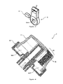
Figure 1 is a perspective schematic view of a control panel of the cooking appliance prior to assembly. -
Figure 2 is a front schematic view of an electrical unit used in said panel. -
Figure 3 is a perspective schematic view of a magnetic element and its carrier member prior to assembly. -
Figure 4 is a cross-sectional illustration of a rotary control knob in an assembled form. - The parts in said figures are individually numbered as following.
- control panel (A)
- front plate (1)
- rear section (2)
- rotary control knob (3)
- adjustment bar (4)
- carrier member (5)
- magnetic element (6)
- electrical unit (7)
- magnetic sensor (8)
- illuminating element (9)
- hole (10)
- knob body (11)
- transparent part (12)
- knob socket (13)
- bar socket (14)
- magnetic element socket (15)
- hole (16)
- opening (17)
- inner section (18)
- body opening (19)
-
Figure 1 gives a perspective schematic view of a control panel (A) provided in a cooking appliance (not illustrated in figures) according to the present invention, which is presented in an assembled form. The cooking appliance control panel (A) here comprises at least one rotary control knob (3) and a front plate (1) just behind the knobs (3); and an equipment at the rear section (2), said equipment remaining behind the plate (1) and ensuring the adjustment of the functions of the cooking appliance. Between this equipment are provided components (not illustrated in figures), e.g. valves for gas cookers, potentiometers for electrical cookers, etc. and an electrical unit (7) with the following details. - Said electrical unit (7) is illustrated in
figures 1 and 2 , and is preferably made in the form of a printed circuit board, in terms of production and assembly easiness. In the electrical unit (7) are provided at least one magnetic sensor (8) and illuminating element (9) (e.g. LED or bulb). This sensor (8) determines if light is to be emitted from the illuminating element (9). When a magnetic element (6) (seefigures 1 and3 ) comes in front of the sensor (8), the sensor (8) interrupts the electricity supply to the illuminating element (9). And when the magnetic element (6) is moved away from the sensor (8) (i.e. when the knob (3) is rotated), the electricity supply to the illuminating element (9) is opened so that the elements (9) start emitting light. (An adjustment bar (4) mentioned below is passed through a hole (16) shown on the electrical unit (7). The periphery of the hole (16) is likewise provided with a sensor (8) and illuminating elements (9).) -
Figure 3 is a perspective schematic view of the magnetic element (6) and carrier member (5) prior to assembly. The carrier member (5) is designed to place the magnetic element (6) thereon. For this purpose, the magnetic element (6) is placed into a socket (15) provided on the member (5), wherein this magnetic element (6) changes its position according to the movement of the carrier member (5). On the carrier member (5) is provided also a separate socket (14) for fitting the member (5) to the adjustment bar (4) (seeFigure 1 ) (the adjustment bar (4) is introduced into this socket (14)). - The adjustment bar (4) illustrated in
Figure 1 , in turn, is used to adjust the parts (i.e. gas or electrical heaters) such as a gas valve or a potentiometer of an electrical heater (not illustrated in figures). The rotary control knob (3) is fitted onto the adjustment bar (4), such that when the knob (3) is rotated, the adjustment bar (4) is rotated as well. Thus, the magnetic element (6) on the carrier member (5) fitted to the adjustment bar (4) also changes its position when the bar (4) is rotated. - When the adjustment bar (4) is brought to a certain angular position, the magnetic member (6) comes against the magnetic sensor (8) and in this position (this position is the null or closed position of the knob (3)) the sensor (8) interrupts the electricity supply to the illuminating element (9), as mentioned above. With rotating the adjustment bar (4), the magnetic member (6) is brought far from the sensor (8) and in this case electricity is supplied to said elements (9).
- The illumination of the illuminating elements (9) is an indication that the gas cookers or electric heaters are in an operative state. It is ensured with this invention to deliver the light emitted from the illuminating elements (9) to a user via the rotary control knob (3), and to indicate that the respective functions are conducted in relation to that knob (3). The knob (3) structure illustrated in
figures 1 and4 are developed for this purpose. The rotary control knob (3) here is fitted to the adjustment bar (4) passed through the interior of the hole (10) on the front plate (1). The knob (3) comprises an opaque knob body (11) and a knob socket (13), as well as at least one transparent member (12), provided in an inner section (18) remaining therebetween (11, 13). At least one opening (17) is provided on the knob socket (13), these openings (17) facing the illuminating elements (9) when the knob (3) is in a form mounted to the panel (A). The light emitted from the illuminating elements (9) is passed through these openings (17) and illuminates the inner section (18) of the opaque knob body (11). As for the transparent member (12) provided in the inner section (18), it gives the light out through at least one body opening (19) provided on the knob body (11).
Claims (5)
- A cooking appliance control panel (A), comprising at least one rotary control knob (3) provided at the front thereof; and one adjustment bar (4) for each knob, provided at the rear section (2) thereof, each of said bars coupled to an individual knob (3) to adjust the operation of the respective heaters of the appliance, characterized by further comprising
a carrier member (5) fitted to the adjustment bar (4) and provided with a magnetic element (6); and
an electrical unit (7) provided with at least one magnetic sensor (8) and illuminating element (9);
wherein
the light emitted from the illuminating element (9) is passed through the interior of the knob (3) and
when a magnetic element (6) faces, or comes in front of, the sensor (8) with rotating the knob (3), the sensor (8) interrupts the electricity supply to the illuminating element (9). - The cooking appliance control panel (A) according to Claim 1, characterized in that said knob (3) comprises an opaque knob body (11) and a knob socket (13), as well as at least one transparent member (12), provided in an inner section (18) remaining therebetween (11, 13).
- The cooking appliance control panel (A) according to Claim 2, characterized by comprising at least one opening (17) on the knob socket (13) in a manner facing said illuminating element (9), the light emitted from the illuminating element (9) being passed through this opening to reach the inner section (18).
- The cooking appliance control panel (A) according to Claim 2, characterized by comprising at least one body opening (19) on the knob body (11), through which the light passing through the transparent member (12) at the inner section (18) is given out.
- The cooking appliance control panel (A) according to Claim 1, characterized in that a hole (16) is provided in the electrical unit (7), the periphery of said hole (16) being provided with a magnetic sensor (8) and illuminating element (9), and the adjustment bar (4) being passed through this hole (16).
Applications Claiming Priority (1)
| Application Number | Priority Date | Filing Date | Title |
|---|---|---|---|
| TR2010/09902A TR201009902A2 (en) | 2010-11-30 | 2010-11-30 | A cooking appliance control panel |
Publications (1)
| Publication Number | Publication Date |
|---|---|
| EP2458287A1 true EP2458287A1 (en) | 2012-05-30 |
Family
ID=44950122
Family Applications (1)
| Application Number | Title | Priority Date | Filing Date |
|---|---|---|---|
| EP11190818A Withdrawn EP2458287A1 (en) | 2010-11-30 | 2011-11-25 | Control panel of a cooking appliance |
Country Status (2)
| Country | Link |
|---|---|
| EP (1) | EP2458287A1 (en) |
| TR (1) | TR201009902A2 (en) |
Cited By (7)
| Publication number | Priority date | Publication date | Assignee | Title |
|---|---|---|---|---|
| WO2013122555A3 (en) * | 2012-02-16 | 2013-11-21 | Semtech Elektronik Sanayi Ve Ticaret Limited Sirketi | Contactless controllable illuminated control mechanism |
| JP2016035853A (en) * | 2014-08-04 | 2016-03-17 | 三菱電機株式会社 | Cooker |
| EP3026687A1 (en) * | 2014-11-25 | 2016-06-01 | E.G.O. ELEKTRO-GERÄTEBAU GmbH | Operating device for an electrical device and electrical device |
| WO2016082891A1 (en) * | 2014-11-28 | 2016-06-02 | Arcelik Anonim Sirketi | Illuminated rotary knob for use in a household appliance |
| IT201700014858A1 (en) * | 2017-02-10 | 2018-08-10 | Bitron Spa | CONTROL PANEL FOR APPLIANCES AND RELATED APPLIANCE DEVICE. |
| WO2018212733A3 (en) * | 2016-11-03 | 2019-02-21 | İmren Plasti̇k Sanayi̇ Ve Ti̇caret Li̇mi̇ted Şi̇rketi̇ | A knob |
| WO2024177587A3 (en) * | 2023-02-24 | 2024-09-26 | Ferel Elektronik San. Ve Tic. A.S. | A switch assembly for a cooking device |
Citations (4)
| Publication number | Priority date | Publication date | Assignee | Title |
|---|---|---|---|---|
| US4446455A (en) * | 1981-02-27 | 1984-05-01 | Nashawaty Ralph G | Stove alarm system |
| EP0600780A1 (en) * | 1992-12-04 | 1994-06-08 | Société SCHOLTES | Control switch for a domestic cooking appliance |
| DE10134395A1 (en) * | 2001-07-14 | 2003-01-30 | Grundig Ag | Illuminated turning device for adjusting the operation of appliances has an illuminated turning knob turning on an operating element with an illuminated ring area |
| US6733146B1 (en) | 2003-01-10 | 2004-05-11 | Pat J. Vastano | Illuminated knob for indicating the operative condition of an appliance |
-
2010
- 2010-11-30 TR TR2010/09902A patent/TR201009902A2/en unknown
-
2011
- 2011-11-25 EP EP11190818A patent/EP2458287A1/en not_active Withdrawn
Patent Citations (4)
| Publication number | Priority date | Publication date | Assignee | Title |
|---|---|---|---|---|
| US4446455A (en) * | 1981-02-27 | 1984-05-01 | Nashawaty Ralph G | Stove alarm system |
| EP0600780A1 (en) * | 1992-12-04 | 1994-06-08 | Société SCHOLTES | Control switch for a domestic cooking appliance |
| DE10134395A1 (en) * | 2001-07-14 | 2003-01-30 | Grundig Ag | Illuminated turning device for adjusting the operation of appliances has an illuminated turning knob turning on an operating element with an illuminated ring area |
| US6733146B1 (en) | 2003-01-10 | 2004-05-11 | Pat J. Vastano | Illuminated knob for indicating the operative condition of an appliance |
Cited By (8)
| Publication number | Priority date | Publication date | Assignee | Title |
|---|---|---|---|---|
| WO2013122555A3 (en) * | 2012-02-16 | 2013-11-21 | Semtech Elektronik Sanayi Ve Ticaret Limited Sirketi | Contactless controllable illuminated control mechanism |
| JP2016035853A (en) * | 2014-08-04 | 2016-03-17 | 三菱電機株式会社 | Cooker |
| EP3026687A1 (en) * | 2014-11-25 | 2016-06-01 | E.G.O. ELEKTRO-GERÄTEBAU GmbH | Operating device for an electrical device and electrical device |
| WO2016082891A1 (en) * | 2014-11-28 | 2016-06-02 | Arcelik Anonim Sirketi | Illuminated rotary knob for use in a household appliance |
| WO2018212733A3 (en) * | 2016-11-03 | 2019-02-21 | İmren Plasti̇k Sanayi̇ Ve Ti̇caret Li̇mi̇ted Şi̇rketi̇ | A knob |
| IT201700014858A1 (en) * | 2017-02-10 | 2018-08-10 | Bitron Spa | CONTROL PANEL FOR APPLIANCES AND RELATED APPLIANCE DEVICE. |
| EP3360458A1 (en) * | 2017-02-10 | 2018-08-15 | Bitron S.p.A. | Control panel for household applicances and household appliance thereof |
| WO2024177587A3 (en) * | 2023-02-24 | 2024-09-26 | Ferel Elektronik San. Ve Tic. A.S. | A switch assembly for a cooking device |
Also Published As
| Publication number | Publication date |
|---|---|
| TR201009902A2 (en) | 2011-07-21 |
Similar Documents
| Publication | Publication Date | Title |
|---|---|---|
| EP2458287A1 (en) | Control panel of a cooking appliance | |
| EP2659190B1 (en) | A household appliance comprising a knob the outer periphery of which is illuminated | |
| CN102597627B (en) | Device for controlling gas supply to a burner | |
| EP3332413B1 (en) | Illuminated rotary knob for household appliance | |
| EP2516928B1 (en) | Lighting control switch harness for gas taps of for cooking appliances with optical indication of opening of the gas tap | |
| US9194589B2 (en) | Control knob for stoves and ovens | |
| US20110146650A1 (en) | Operator control for a domestic appliance and method for operating a display unit | |
| EP3483502B1 (en) | Gas cooking appliance | |
| MX2011007469A (en) | Holding device for an operating device. | |
| WO2014102384A1 (en) | An illuminated knob, a switching mechanism for the illuminated knob and a gas/electric cooking appliance wherein the same are used | |
| CN101248313B (en) | Timer for a gas cooking hob | |
| WO2013122555A2 (en) | Contactless controllable illuminated control mechanism | |
| EP2980486A1 (en) | Operation apparatus for cooktop, and cooktop | |
| US7819540B2 (en) | Control device for an appliance | |
| US11567525B1 (en) | Illuminated knob for an appliance | |
| JP2019032098A (en) | Gas cooking stove | |
| US11781756B2 (en) | Gas grill and control method thereof | |
| US20230324050A1 (en) | Control knob, control system and household appliance | |
| US10409314B2 (en) | Integrated housing for components of a cooking appliance | |
| CN216976839U (en) | Luminous knob | |
| EP2531774A2 (en) | Timer of a household gas burner | |
| CN216768537U (en) | Knob device with temperature control gear valve | |
| CN211582714U (en) | Cooking utensil | |
| PL1847780T3 (en) | Domestic cooking oven | |
| US20210141410A1 (en) | Backlit knob |
Legal Events
| Date | Code | Title | Description |
|---|---|---|---|
| PUAI | Public reference made under article 153(3) epc to a published international application that has entered the european phase |
Free format text: ORIGINAL CODE: 0009012 |
|
| AK | Designated contracting states |
Kind code of ref document: A1 Designated state(s): AL AT BE BG CH CY CZ DE DK EE ES FI FR GB GR HR HU IE IS IT LI LT LU LV MC MK MT NL NO PL PT RO RS SE SI SK SM TR |
|
| AX | Request for extension of the european patent |
Extension state: BA ME |
|
| 17P | Request for examination filed |
Effective date: 20120907 |
|
| STAA | Information on the status of an ep patent application or granted ep patent |
Free format text: STATUS: THE APPLICATION IS DEEMED TO BE WITHDRAWN |
|
| 18D | Application deemed to be withdrawn |
Effective date: 20121201 |