EP2458250A1 - Gear change device for a motor-vehicle - Google Patents
Gear change device for a motor-vehicle Download PDFInfo
- Publication number
- EP2458250A1 EP2458250A1 EP10192850A EP10192850A EP2458250A1 EP 2458250 A1 EP2458250 A1 EP 2458250A1 EP 10192850 A EP10192850 A EP 10192850A EP 10192850 A EP10192850 A EP 10192850A EP 2458250 A1 EP2458250 A1 EP 2458250A1
- Authority
- EP
- European Patent Office
- Prior art keywords
- gear wheel
- gear
- reverse gear
- shaft
- shafts
- Prior art date
- Legal status (The legal status is an assumption and is not a legal conclusion. Google has not performed a legal analysis and makes no representation as to the accuracy of the status listed.)
- Granted
Links
Images


Classifications
-
- F—MECHANICAL ENGINEERING; LIGHTING; HEATING; WEAPONS; BLASTING
- F16—ENGINEERING ELEMENTS AND UNITS; GENERAL MEASURES FOR PRODUCING AND MAINTAINING EFFECTIVE FUNCTIONING OF MACHINES OR INSTALLATIONS; THERMAL INSULATION IN GENERAL
- F16H—GEARING
- F16H3/00—Toothed gearings for conveying rotary motion with variable gear ratio or for reversing rotary motion
- F16H3/006—Toothed gearings for conveying rotary motion with variable gear ratio or for reversing rotary motion power being selectively transmitted by parallel flow paths, e.g. dual clutch transmissions
-
- F—MECHANICAL ENGINEERING; LIGHTING; HEATING; WEAPONS; BLASTING
- F16—ENGINEERING ELEMENTS AND UNITS; GENERAL MEASURES FOR PRODUCING AND MAINTAINING EFFECTIVE FUNCTIONING OF MACHINES OR INSTALLATIONS; THERMAL INSULATION IN GENERAL
- F16H—GEARING
- F16H57/00—General details of gearing
- F16H57/02—Gearboxes; Mounting gearing therein
- F16H57/021—Shaft support structures, e.g. partition walls, bearing eyes, casing walls or covers with bearings
-
- F—MECHANICAL ENGINEERING; LIGHTING; HEATING; WEAPONS; BLASTING
- F16—ENGINEERING ELEMENTS AND UNITS; GENERAL MEASURES FOR PRODUCING AND MAINTAINING EFFECTIVE FUNCTIONING OF MACHINES OR INSTALLATIONS; THERMAL INSULATION IN GENERAL
- F16H—GEARING
- F16H63/00—Control outputs from the control unit to change-speed- or reversing-gearings for conveying rotary motion or to other devices than the final output mechanism
- F16H63/40—Control outputs from the control unit to change-speed- or reversing-gearings for conveying rotary motion or to other devices than the final output mechanism comprising signals other than signals for actuating the final output mechanisms
- F16H63/48—Signals to a parking brake or parking lock; Control of parking locks or brakes being part of the transmission
-
- F—MECHANICAL ENGINEERING; LIGHTING; HEATING; WEAPONS; BLASTING
- F16—ENGINEERING ELEMENTS AND UNITS; GENERAL MEASURES FOR PRODUCING AND MAINTAINING EFFECTIVE FUNCTIONING OF MACHINES OR INSTALLATIONS; THERMAL INSULATION IN GENERAL
- F16H—GEARING
- F16H3/00—Toothed gearings for conveying rotary motion with variable gear ratio or for reversing rotary motion
- F16H3/02—Toothed gearings for conveying rotary motion with variable gear ratio or for reversing rotary motion without gears having orbital motion
- F16H3/08—Toothed gearings for conveying rotary motion with variable gear ratio or for reversing rotary motion without gears having orbital motion exclusively or essentially with continuously meshing gears, that can be disengaged from their shafts
- F16H3/087—Toothed gearings for conveying rotary motion with variable gear ratio or for reversing rotary motion without gears having orbital motion exclusively or essentially with continuously meshing gears, that can be disengaged from their shafts characterised by the disposition of the gears
- F16H3/093—Toothed gearings for conveying rotary motion with variable gear ratio or for reversing rotary motion without gears having orbital motion exclusively or essentially with continuously meshing gears, that can be disengaged from their shafts characterised by the disposition of the gears with two or more countershafts
- F16H2003/0931—Toothed gearings for conveying rotary motion with variable gear ratio or for reversing rotary motion without gears having orbital motion exclusively or essentially with continuously meshing gears, that can be disengaged from their shafts characterised by the disposition of the gears with two or more countershafts each countershaft having an output gear meshing with a single common gear on the output shaft
-
- F—MECHANICAL ENGINEERING; LIGHTING; HEATING; WEAPONS; BLASTING
- F16—ENGINEERING ELEMENTS AND UNITS; GENERAL MEASURES FOR PRODUCING AND MAINTAINING EFFECTIVE FUNCTIONING OF MACHINES OR INSTALLATIONS; THERMAL INSULATION IN GENERAL
- F16H—GEARING
- F16H2200/00—Transmissions for multiple ratios
- F16H2200/003—Transmissions for multiple ratios characterised by the number of forward speeds
- F16H2200/0047—Transmissions for multiple ratios characterised by the number of forward speeds the gear ratios comprising five forward speeds
-
- F—MECHANICAL ENGINEERING; LIGHTING; HEATING; WEAPONS; BLASTING
- F16—ENGINEERING ELEMENTS AND UNITS; GENERAL MEASURES FOR PRODUCING AND MAINTAINING EFFECTIVE FUNCTIONING OF MACHINES OR INSTALLATIONS; THERMAL INSULATION IN GENERAL
- F16H—GEARING
- F16H2200/00—Transmissions for multiple ratios
- F16H2200/003—Transmissions for multiple ratios characterised by the number of forward speeds
- F16H2200/0052—Transmissions for multiple ratios characterised by the number of forward speeds the gear ratios comprising six forward speeds
-
- F—MECHANICAL ENGINEERING; LIGHTING; HEATING; WEAPONS; BLASTING
- F16—ENGINEERING ELEMENTS AND UNITS; GENERAL MEASURES FOR PRODUCING AND MAINTAINING EFFECTIVE FUNCTIONING OF MACHINES OR INSTALLATIONS; THERMAL INSULATION IN GENERAL
- F16H—GEARING
- F16H2200/00—Transmissions for multiple ratios
- F16H2200/003—Transmissions for multiple ratios characterised by the number of forward speeds
- F16H2200/0056—Transmissions for multiple ratios characterised by the number of forward speeds the gear ratios comprising seven forward speeds
-
- F—MECHANICAL ENGINEERING; LIGHTING; HEATING; WEAPONS; BLASTING
- F16—ENGINEERING ELEMENTS AND UNITS; GENERAL MEASURES FOR PRODUCING AND MAINTAINING EFFECTIVE FUNCTIONING OF MACHINES OR INSTALLATIONS; THERMAL INSULATION IN GENERAL
- F16H—GEARING
- F16H3/00—Toothed gearings for conveying rotary motion with variable gear ratio or for reversing rotary motion
- F16H3/02—Toothed gearings for conveying rotary motion with variable gear ratio or for reversing rotary motion without gears having orbital motion
- F16H3/08—Toothed gearings for conveying rotary motion with variable gear ratio or for reversing rotary motion without gears having orbital motion exclusively or essentially with continuously meshing gears, that can be disengaged from their shafts
- F16H3/087—Toothed gearings for conveying rotary motion with variable gear ratio or for reversing rotary motion without gears having orbital motion exclusively or essentially with continuously meshing gears, that can be disengaged from their shafts characterised by the disposition of the gears
- F16H3/093—Toothed gearings for conveying rotary motion with variable gear ratio or for reversing rotary motion without gears having orbital motion exclusively or essentially with continuously meshing gears, that can be disengaged from their shafts characterised by the disposition of the gears with two or more countershafts
-
- Y—GENERAL TAGGING OF NEW TECHNOLOGICAL DEVELOPMENTS; GENERAL TAGGING OF CROSS-SECTIONAL TECHNOLOGIES SPANNING OVER SEVERAL SECTIONS OF THE IPC; TECHNICAL SUBJECTS COVERED BY FORMER USPC CROSS-REFERENCE ART COLLECTIONS [XRACs] AND DIGESTS
- Y10—TECHNICAL SUBJECTS COVERED BY FORMER USPC
- Y10T—TECHNICAL SUBJECTS COVERED BY FORMER US CLASSIFICATION
- Y10T74/00—Machine element or mechanism
- Y10T74/19—Gearing
- Y10T74/19023—Plural power paths to and/or from gearing
- Y10T74/19051—Single driven plural drives
- Y10T74/19065—Aligned
-
- Y—GENERAL TAGGING OF NEW TECHNOLOGICAL DEVELOPMENTS; GENERAL TAGGING OF CROSS-SECTIONAL TECHNOLOGIES SPANNING OVER SEVERAL SECTIONS OF THE IPC; TECHNICAL SUBJECTS COVERED BY FORMER USPC CROSS-REFERENCE ART COLLECTIONS [XRACs] AND DIGESTS
- Y10—TECHNICAL SUBJECTS COVERED BY FORMER USPC
- Y10T—TECHNICAL SUBJECTS COVERED BY FORMER US CLASSIFICATION
- Y10T74/00—Machine element or mechanism
- Y10T74/19—Gearing
- Y10T74/19219—Interchangeably locked
- Y10T74/19228—Multiple concentric clutch shafts
-
- Y—GENERAL TAGGING OF NEW TECHNOLOGICAL DEVELOPMENTS; GENERAL TAGGING OF CROSS-SECTIONAL TECHNOLOGIES SPANNING OVER SEVERAL SECTIONS OF THE IPC; TECHNICAL SUBJECTS COVERED BY FORMER USPC CROSS-REFERENCE ART COLLECTIONS [XRACs] AND DIGESTS
- Y10—TECHNICAL SUBJECTS COVERED BY FORMER USPC
- Y10T—TECHNICAL SUBJECTS COVERED BY FORMER US CLASSIFICATION
- Y10T74/00—Machine element or mechanism
- Y10T74/19—Gearing
- Y10T74/19219—Interchangeably locked
- Y10T74/19233—Plurality of counter shafts
Definitions
- the present invention refers to gear change devices for motor vehicles, of the type comprising:
- a gear change device of the above indicated type is described in DE 10 2004 056 936 and in the corresponding US 7,690,278 B2 and WO 2006/0563252 .
- the object of the present invention is that of providing a gear change device of the above indicated type which is simple and functional from a construction point of view.
- an object of the present invention is that of providing a gear change device of the above indicated type which can be designed with greater flexibility of choice for the positioning of the various components thereof, according to the available spaces.
- the invention provides a gear change device having all the above indicated features and further characterized in that the abovementioned parking gear wheel is mounted adjacent to a roller bearing which rotatably supports said first secondary shaft and which is interposed axially between said parking gear wheel and said first reverse gear wheel.
- a gear change device for a motor vehicle comprising a first primary shaft 1A and a second primary shaft 1B coaxial with respect to each other, whose right ends (with reference to the figures) are selectively connectable to the driving shaft of a motor vehicle by means of a double clutch engagement device of any known type (not illustrated) is indicated in its entirety with number 1.
- a first and a second secondary shaft whose axes are parallel and spaced from the common axis of the two primary shafts 1A, 1B are indicated in their entirety with references 2A, 2B.
- the figures show the shafts 1A, 1B, 2A, 2B as if the three axes thereof were arranged in the same plane, while such axes actually are not coplanar, but they are arranged to form a triangle.
- All the abovementioned shafts are rotatably supported by means of roller bearings 3 within the casing 4 of the gearbox.
- the two secondary shafts 2A, 2B have - at the right ends thereof (with reference to the figures) - output gear wheels u intended to mesh both, in a per se known manner, with a gear wheel of a differential (not illustrated).
- the illustrated gear change device has a plurality of pairs of gear wheels, corresponding to the plurality of forward gear ratios and to one reverse gear ratio, wherein the gear wheels of each pair are one rigidly connected in rotation with one of the primary shafts or with one of the secondary shafts, while the other is freely rotatable respectively, in both cases, on one of the secondary shafts or on one of the primary shafts.
- the device comprises a plurality of gear selector devices suitable for rotatably coupling each of said freely rotatable gear wheels with the shaft on which it is mounted.
- references I, II, III, IV, V, VI, VII, R1 respectively indicate gear wheels freely rotatably mounted on the first or on the second secondary shaft 2A, 2B and couplable with the respective secondary shaft for respectively selecting the first, second, third, fourth, fifth, sixth, seventh gears and the reverse gear.
- the gear wheel I meshes with a gear wheel 10 rigidly and permanently connected in rotation with the first primary shaft 1 A, i.e. on the inner primary shaft, on one end portion thereof extending beyond the end of the second primary shaft 1B.
- the gear wheel II of the second gear meshes with a gear wheel 20 rigidly connected to the primary shaft 1B.
- the gear wheel III of the third gear meshes with a gear wheel 30 rigidly connected to the primary shaft 1A.
- the gear wheel IV of the fourth gear and the gear wheel VI of the sixth gear both mesh with the same gear wheel 46 rigidly connected to the primary shaft 1B.
- the gear wheel V of the fifth gear and the gear wheel VII of the seventh gear both mesh with the same gear wheel 57 rigidly connected to the primary shaft 1A.
- the selector devices for rotatably coupling each of the gear wheels I, II, III, IV, V, VI, VII, R1 are indicated with references S1/7, S2/6, S3/5, S4/R, each of such selector devices being actuatable in opposite directions for selecting different gears (the digits of the number that follows the reference S indicate the gears thus selectable).
- the second forward gear is defined by a pair of gear wheels 20,II, the first permanently connected in rotation with the outermost primary shaft 1B and the other mounted freely rotatable on the second secondary shaft 2B and rotatably couplable therewith through an engagement device schematically illustrated in the drawing and indicated with reference S2/6 (to indicate that such device selects the second gear in one direction and the sixth gear in the other direction).
- the reverse gear ratio is defined by the first reverse gear wheel R1 which is mounted freely rotatable on the first secondary shaft 2A and it is rotatably couplable therewith through the selector device S4/R and by a second reverse gear wheel R2, which serves as an idler gear wheel for inverting the motion and which meshes with the first gear wheel R1 (such meshing, diagrammatically shown in the figure by a dashed line, being possible due to that the two axes of the secondary shafts and the common axis of the primary shafts are not contained in the same plane).
- the second reverse gear wheel R2 is permanently connected in rotation with the gear wheel II of the second gear and it is mounted freely rotatable connected on the second secondary shaft 2B.
- the engagement of the reverse gear is obtained by activating the selector device S4/R and leaving the selector device S2/6 disabled, so as to leave the second reverse gear wheel R2 freely rotatable on the second secondary shaft 2B.
- the motion coming from the outermost primary shaft 1B is transferred to the gear wheel II and therefrom to the gear wheel R2, to the gear wheel R1 and to the first secondary shaft 2A.
- a parking gear wheel P cooperating with a parking device B which can be of any known type (illustrated solely schematically in the drawings) for locking the gear change device in the parking condition is rigidly mounted on the first secondary shaft 2A.
- the parking gear wheel P is mounted adjacent to a roller bearing (3') which rotatably supports said first secondary shaft (2A) within the casing 4 and which is axially interposed between said parking gear wheel (P) and said first reverse gear wheel (R1).
- a roller bearing (3') which rotatably supports said first secondary shaft (2A) within the casing 4 and which is axially interposed between said parking gear wheel (P) and said first reverse gear wheel (R1).
- the gear change device besides maintaining all the characteristic advantages of the abovementioned device, facilitates the designer in that it allows a wider range of choice when arranging the various elements of the gearbox, and in particular the elements associated to the lock device for the parking according to the available spaces.
Landscapes
- Engineering & Computer Science (AREA)
- General Engineering & Computer Science (AREA)
- Mechanical Engineering (AREA)
- Structure Of Transmissions (AREA)
- Gear-Shifting Mechanisms (AREA)
Abstract
Description
- The present invention refers to gear change devices for motor vehicles, of the type comprising:
- a first and a second primary shaft coaxial with respect to each other, selectively connectable to the driving shaft of the motor vehicle by means of a double clutch engagement device,
- a first and a second secondary shaft, whose axes are parallel and spaced from the common axis of said primary shafts, and having respective output gear wheels intended to mesh with the gear wheel of a differential,
- a plurality of pairs of gear wheels, corresponding to a plurality of forward gear ratios and to at least one reverse gear ratio, wherein the gear wheels of each pair are one rigidly connected in rotation with one of the primary shafts or with one of the secondary shafts while the other is freely rotatable on one of the secondary shafts or on one of the primary shafts respectively,
- a plurality of gear selector devices for rotatably coupling each of said freely rotatable gear wheels with the shaft on which it is mounted,
- wherein the reverse gear ratio is defined by:
- a first reverse gear wheel mounted freely rotatable on the first secondary shaft and connectable in rotation with the latter by means of one of said selector devices, with the aim of selecting the reverse gear,
- a second reverse gear wheel, which serves as an idler gear wheel for inverting the motion, which meshes with said first reverse gear wheel and which is mounted freely rotatable on the second secondary shaft, said second reverse gear wheel being permanently connected in rotation with a forward gear wheel which is mounted freely rotatable on the abovementioned second secondary shaft and meshes with a gear wheel rotatably rigidly connected on one of said primary shafts,
- wherein a parking gear wheel is operatively connected to said first secondary shaft cooperating with a lock device for locking the gear change device in the parking condition.
- A gear change device of the above indicated type is described in
DE 10 2004 056 936US 7,690,278 B2 andWO 2006/0563252 - The object of the present invention is that of providing a gear change device of the above indicated type which is simple and functional from a construction point of view. In particular an object of the present invention is that of providing a gear change device of the above indicated type which can be designed with greater flexibility of choice for the positioning of the various components thereof, according to the available spaces.
- With the aim of attaining such object, the invention provides a gear change device having all the above indicated features and further characterized in that the abovementioned parking gear wheel is mounted adjacent to a roller bearing which rotatably supports said first secondary shaft and which is interposed axially between said parking gear wheel and said first reverse gear wheel.
- The present invention shall now be described with reference to the attached drawings, purely provided by way of example, wherein:
-
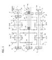
figure 1 is a diagram of a first embodiment of the gear change device according to the invention, and -
figures 2 ,3 are diagrams of two further embodiments of the gear change device according to the invention. - With reference to
figure 1 , a gear change device for a motor vehicle, comprising a firstprimary shaft 1A and a secondprimary shaft 1B coaxial with respect to each other, whose right ends (with reference to the figures) are selectively connectable to the driving shaft of a motor vehicle by means of a double clutch engagement device of any known type (not illustrated) is indicated in its entirety withnumber 1. - A first and a second secondary shaft, whose axes are parallel and spaced from the common axis of the two
primary shafts references - For better clarity, the figures show the
shafts - All the abovementioned shafts are rotatably supported by means of
roller bearings 3 within thecasing 4 of the gearbox. - The two
secondary shafts - The illustrated gear change device has a plurality of pairs of gear wheels, corresponding to the plurality of forward gear ratios and to one reverse gear ratio, wherein the gear wheels of each pair are one rigidly connected in rotation with one of the primary shafts or with one of the secondary shafts, while the other is freely rotatable respectively, in both cases, on one of the secondary shafts or on one of the primary shafts. Furthermore, still according to the conventional art, the device comprises a plurality of gear selector devices suitable for rotatably coupling each of said freely rotatable gear wheels with the shaft on which it is mounted.
- In the specific case illustrated in
figure 1 , references I, II, III, IV, V, VI, VII, R1 respectively indicate gear wheels freely rotatably mounted on the first or on the secondsecondary shaft - The gear wheel I meshes with a
gear wheel 10 rigidly and permanently connected in rotation with the firstprimary shaft 1 A, i.e. on the inner primary shaft, on one end portion thereof extending beyond the end of the secondprimary shaft 1B. - The gear wheel II of the second gear meshes with a
gear wheel 20 rigidly connected to theprimary shaft 1B. - The gear wheel III of the third gear meshes with a
gear wheel 30 rigidly connected to theprimary shaft 1A. - The gear wheel IV of the fourth gear and the gear wheel VI of the sixth gear both mesh with the
same gear wheel 46 rigidly connected to theprimary shaft 1B. - The gear wheel V of the fifth gear and the gear wheel VII of the seventh gear both mesh with the
same gear wheel 57 rigidly connected to theprimary shaft 1A. - The selector devices for rotatably coupling each of the gear wheels I, II, III, IV, V, VI, VII, R1 are indicated with references S1/7, S2/6, S3/5, S4/R, each of such selector devices being actuatable in opposite directions for selecting different gears (the digits of the number that follows the reference S indicate the gears thus selectable).
- The second forward gear is defined by a pair of
gear wheels 20,II, the first permanently connected in rotation with the outermostprimary shaft 1B and the other mounted freely rotatable on the secondsecondary shaft 2B and rotatably couplable therewith through an engagement device schematically illustrated in the drawing and indicated with reference S2/6 (to indicate that such device selects the second gear in one direction and the sixth gear in the other direction). - The reverse gear ratio is defined by the first reverse gear wheel R1 which is mounted freely rotatable on the first
secondary shaft 2A and it is rotatably couplable therewith through the selector device S4/R and by a second reverse gear wheel R2, which serves as an idler gear wheel for inverting the motion and which meshes with the first gear wheel R1 (such meshing, diagrammatically shown in the figure by a dashed line, being possible due to that the two axes of the secondary shafts and the common axis of the primary shafts are not contained in the same plane). The second reverse gear wheel R2 is permanently connected in rotation with the gear wheel II of the second gear and it is mounted freely rotatable connected on the secondsecondary shaft 2B. - With the arrangement described above, the engagement of the reverse gear is obtained by activating the selector device S4/R and leaving the selector device S2/6 disabled, so as to leave the second reverse gear wheel R2 freely rotatable on the second
secondary shaft 2B. In such situation, the motion coming from the outermostprimary shaft 1B is transferred to the gear wheel II and therefrom to the gear wheel R2, to the gear wheel R1 and to the firstsecondary shaft 2A. - In all solutions illustrated in
figures 1 ,2 a parking gear wheel P cooperating with a parking device B which can be of any known type (illustrated solely schematically in the drawings) for locking the gear change device in the parking condition is rigidly mounted on the firstsecondary shaft 2A. - According to the invention, the parking gear wheel P is mounted adjacent to a roller bearing (3') which rotatably supports said first secondary shaft (2A) within the
casing 4 and which is axially interposed between said parking gear wheel (P) and said first reverse gear wheel (R1). Such characteristic is present in all solutions illustrated infigures 1-4 . - Due to the above indicated characteristics, the gear change device according to the invention, besides maintaining all the characteristic advantages of the abovementioned device, facilitates the designer in that it allows a wider range of choice when arranging the various elements of the gearbox, and in particular the elements associated to the lock device for the parking according to the available spaces.
- The solutions illustrated in
figures 2 ,3 differ from that offigure 1 solely due to the fact that they provide for only six gears (figure 2 ) or only five gears (figure 3 ). In such figures, the common parts are indicated using the same reference numbers. The six-gear gearbox offigure 2 differs from the seven-gear one offigure 1 simply due to the elimination of the gear wheel VII of the seventh gear, hence the gear selector S1 operates only in one direction, to select the first gear. The five-gear gearbox offigure 3 differs from the six-gear one offigure 2 simply due to the elimination of the gear wheel VI of the sixth gear, hence the gear selector S2 operates solely in one direction, to select the second gear. - Obviously, without prejudice to the principle of the invention, the construction details and the embodiments may widely vary with respect to what has been described and illustrated purely by way of example, without departing from the scope of protection of the present invention.
Claims (1)
- Gear change device for a motor vehicle, comprising:- a first and a second primary shaft (1A, 1B) coaxial with respect to each other, selectively connectable to the driving shaft of the motor vehicle by means of a double clutch engagement device,- a first and a second secondary shaft (2A, 2B), whose axes are parallel and spaced from the common axis of said primary shafts, and having respective output gear wheels (u) intended to mesh with the gear wheel of a differential,- a plurality of pairs of gear wheels (10,I; 20,II, 30,III; 46,IV; 57,V; 46,VI; 57,VII), corresponding to a plurality of forward gear ratios and to at least one reverse gear ratio, wherein the gear wheels of each pair are one rigidly connected in rotation with one of the primary shafts (1A,1B) or with one of the secondary shafts while the other is freely rotatable respectively on one of the secondary shafts (2A, 2B) or on one of the primary shafts,- a plurality of gear selector devices (S1/7, S2/6, S3/4, S4/R) for rotatably coupling each of said freely rotatable gear wheels (I, II, III, IV, V, VI, VII, R1) with the shaft (2A, 2B) on which it is mounted,- wherein the reverse gear ratio is defined by:- a first reverse gear wheel (R1) mounted freely rotatable on the first secondary shaft (2A) and connectable in rotation with the latter by means of one of said selector devices (S4/R), with the aim of selecting the reverse gear,- a second reverse gear wheel (R2), which serves as an idler gear wheel for inverting the motion, which meshes with said first reverse gear wheel (R1) and which is mounted freely rotatable on the second secondary shaft (2B), said second reverse gear wheel (R2) being permanently connected in rotation with a forward gear wheel (II) which is mounted freely rotatable on said second secondary shaft (2B) and meshes with a gear wheel (20) rotatably rigidly connected on one of said primary shafts (1B),- wherein a parking gear wheel (P) is rigidly mounted on said first secondary shaft (2A) cooperating with a lock device (B) for locking the gear change device in the parking condition,characterised in that said parking gear wheel P is mounted adjacent to a roller bearing (3') which rotatably supports said first secondary shaft (2A) within the casing (4) and which is axially interposed between said parking gear wheel (P) and said first reverse gear wheel (R1).
Priority Applications (3)
| Application Number | Priority Date | Filing Date | Title |
|---|---|---|---|
| EP10192850A EP2458250B1 (en) | 2010-11-29 | 2010-11-29 | Gear change device for a motor-vehicle |
| US13/112,283 US8978499B2 (en) | 2010-11-29 | 2011-05-20 | Gear change device for a motor vehicle |
| CN201110181551.9A CN102478101B (en) | 2010-11-29 | 2011-06-30 | Gear change device for motor vehicle |
Applications Claiming Priority (1)
| Application Number | Priority Date | Filing Date | Title |
|---|---|---|---|
| EP10192850A EP2458250B1 (en) | 2010-11-29 | 2010-11-29 | Gear change device for a motor-vehicle |
Publications (2)
| Publication Number | Publication Date |
|---|---|
| EP2458250A1 true EP2458250A1 (en) | 2012-05-30 |
| EP2458250B1 EP2458250B1 (en) | 2012-10-31 |
Family
ID=43629605
Family Applications (1)
| Application Number | Title | Priority Date | Filing Date |
|---|---|---|---|
| EP10192850A Active EP2458250B1 (en) | 2010-11-29 | 2010-11-29 | Gear change device for a motor-vehicle |
Country Status (3)
| Country | Link |
|---|---|
| US (1) | US8978499B2 (en) |
| EP (1) | EP2458250B1 (en) |
| CN (1) | CN102478101B (en) |
Cited By (1)
| Publication number | Priority date | Publication date | Assignee | Title |
|---|---|---|---|---|
| CN107035853A (en) * | 2017-06-08 | 2017-08-11 | 吉林大学 | New 16+16 full powers gearshift and commutation gearbox |
Families Citing this family (2)
| Publication number | Priority date | Publication date | Assignee | Title |
|---|---|---|---|---|
| CN107989966B (en) * | 2017-12-26 | 2023-10-03 | 洛阳聚翔机械科技有限公司 | Three-shaft power high-low gear and power reversing transmission assembly of tractor |
| CN110925366B (en) * | 2019-12-19 | 2025-07-08 | 江苏常发农业装备股份有限公司 | Tractor speed change system and tractor |
Citations (4)
| Publication number | Priority date | Publication date | Assignee | Title |
|---|---|---|---|---|
| WO2006056325A2 (en) | 2004-11-23 | 2006-06-01 | Getrag Getriebe- Und Zahnradfabrik Hermann Hagenmeyer Gmbh & Cie Kg | Stepped transmission for a motor vehicle |
| JP2007321821A (en) * | 2006-05-30 | 2007-12-13 | Mitsubishi Motors Corp | Double clutch transmission |
| GB2458790A (en) * | 2008-03-31 | 2009-10-07 | Gm Global Tech Operations Inc | Dual clutch transmission with planetary drive |
| US20100288064A1 (en) * | 2009-05-12 | 2010-11-18 | Gm Global Technology Operations, Inc. | Seven speed dual clutch transmission |
Family Cites Families (15)
| Publication number | Priority date | Publication date | Assignee | Title |
|---|---|---|---|---|
| US4481837A (en) * | 1982-07-12 | 1984-11-13 | Caterpillar Tractor Co. | Multiple speed gear transmission |
| JP3522827B2 (en) * | 1994-05-27 | 2004-04-26 | 本田技研工業株式会社 | Transmission for electric vehicles |
| JP2001221327A (en) * | 2000-02-08 | 2001-08-17 | Honda Motor Co Ltd | Lubrication structure of bearing for output shaft in transmission |
| DE10165097B3 (en) * | 2000-07-18 | 2015-07-23 | Schaeffler Technologies AG & Co. KG | Double clutch |
| DE10040039A1 (en) * | 2000-08-11 | 2002-02-21 | Daimler Chrysler Ag | Change gear assembly |
| DE10059417A1 (en) * | 2000-11-30 | 2002-06-13 | Daimler Chrysler Ag | Parking brake and roller bearing for use in transmission for motor vehicle has pegs preventing rotation of outer race with respect to fixed housing and teeth on gear selector engaging outer race |
| DE10153014A1 (en) * | 2001-10-26 | 2003-05-08 | Volkswagen Ag | Bearing of the input shafts of a double clutch transmission |
| JP2004263708A (en) * | 2003-01-14 | 2004-09-24 | Kyowa Metal Work Co Ltd | Twin clutch type transmission |
| DE102004001278B4 (en) * | 2004-01-07 | 2015-08-13 | Volkswagen Ag | Double clutch transmission for a motor vehicle |
| US7083540B2 (en) | 2004-03-18 | 2006-08-01 | Ford Global Technologies, Llc | Dual clutch transmission having low gear mesh loss |
| JP2007331654A (en) * | 2006-06-16 | 2007-12-27 | Aisin Ai Co Ltd | Gear transmission having parking lock function |
| DE102008021134A1 (en) * | 2008-04-28 | 2009-10-29 | GM Global Technology Operations, Inc., Detroit | Manual transmission for a motor vehicle |
| DE102009018450B4 (en) * | 2009-03-09 | 2011-05-26 | Getrag Ford Transmissions Gmbh | Double clutch |
| EP2436951B1 (en) * | 2010-09-30 | 2013-08-21 | C.R.F. Società Consortile per Azioni | Gear change device for a motor-vehicle |
| EP2602510B1 (en) * | 2011-12-07 | 2014-12-03 | C.R.F. Società Consortile per Azioni | Gear change device for a motor-vehicle |
-
2010
- 2010-11-29 EP EP10192850A patent/EP2458250B1/en active Active
-
2011
- 2011-05-20 US US13/112,283 patent/US8978499B2/en active Active
- 2011-06-30 CN CN201110181551.9A patent/CN102478101B/en active Active
Patent Citations (6)
| Publication number | Priority date | Publication date | Assignee | Title |
|---|---|---|---|---|
| WO2006056325A2 (en) | 2004-11-23 | 2006-06-01 | Getrag Getriebe- Und Zahnradfabrik Hermann Hagenmeyer Gmbh & Cie Kg | Stepped transmission for a motor vehicle |
| DE102004056936A1 (en) | 2004-11-23 | 2006-06-01 | Getrag Getriebe- Und Zahnradfabrik Hermann Hagenmeyer Gmbh & Cie Kg | Variable speed gearbox for a motor vehicle |
| US7690278B2 (en) | 2004-11-23 | 2010-04-06 | Getrag Getriebe- Und Zahnradfabrik Hermann Hagenmeyer Gmbh & Cie Kg | Step variable transmission for a motor vehicle |
| JP2007321821A (en) * | 2006-05-30 | 2007-12-13 | Mitsubishi Motors Corp | Double clutch transmission |
| GB2458790A (en) * | 2008-03-31 | 2009-10-07 | Gm Global Tech Operations Inc | Dual clutch transmission with planetary drive |
| US20100288064A1 (en) * | 2009-05-12 | 2010-11-18 | Gm Global Technology Operations, Inc. | Seven speed dual clutch transmission |
Cited By (2)
| Publication number | Priority date | Publication date | Assignee | Title |
|---|---|---|---|---|
| CN107035853A (en) * | 2017-06-08 | 2017-08-11 | 吉林大学 | New 16+16 full powers gearshift and commutation gearbox |
| CN107035853B (en) * | 2017-06-08 | 2018-08-10 | 吉林大学 | 16+16 full powers are shifted gears and commutation gearbox |
Also Published As
| Publication number | Publication date |
|---|---|
| US20120132031A1 (en) | 2012-05-31 |
| CN102478101A (en) | 2012-05-30 |
| CN102478101B (en) | 2014-12-24 |
| EP2458250B1 (en) | 2012-10-31 |
| US8978499B2 (en) | 2015-03-17 |
Similar Documents
| Publication | Publication Date | Title |
|---|---|---|
| CN106870658B (en) | Multiple-speed gear-box | |
| US20100288064A1 (en) | Seven speed dual clutch transmission | |
| US8438941B2 (en) | Eight speed dual clutch transmission | |
| US8757021B2 (en) | Eight speed dual clutch transmission | |
| EP2500604B1 (en) | Gear change device for a motor-vehicle | |
| EP2602510B1 (en) | Gear change device for a motor-vehicle | |
| US8757020B2 (en) | Seven speed dual clutch transmission | |
| EP2458250B1 (en) | Gear change device for a motor-vehicle | |
| EP2436951B1 (en) | Gear change device for a motor-vehicle | |
| KR20160044556A (en) | Dual-clutch transmission | |
| US10024396B2 (en) | Dual clutch transmission for a motor vehicle | |
| US8336410B2 (en) | Dual clutch multi-speed transmission | |
| EP2746086B1 (en) | Gear-change device for a motor vehicle | |
| EP1866557A1 (en) | Seven-gear gearbox for a motorcar double clutch transmission | |
| US10018251B2 (en) | Multi-speed dual clutch transmission | |
| US7243566B2 (en) | Manual gearbox for a motor vehicle with a front transverse drive | |
| CN103185110A (en) | Shift gearbox for vehicle | |
| US20170138441A1 (en) | Multi-speed dual clutch transmission |
Legal Events
| Date | Code | Title | Description |
|---|---|---|---|
| PUAI | Public reference made under article 153(3) epc to a published international application that has entered the european phase |
Free format text: ORIGINAL CODE: 0009012 |
|
| 17P | Request for examination filed |
Effective date: 20110607 |
|
| AK | Designated contracting states |
Kind code of ref document: A1 Designated state(s): AL AT BE BG CH CY CZ DE DK EE ES FI FR GB GR HR HU IE IS IT LI LT LU LV MC MK MT NL NO PL PT RO RS SE SI SK SM TR |
|
| AX | Request for extension of the european patent |
Extension state: BA ME |
|
| GRAP | Despatch of communication of intention to grant a patent |
Free format text: ORIGINAL CODE: EPIDOSNIGR1 |
|
| RIC1 | Information provided on ipc code assigned before grant |
Ipc: F16H 3/093 20060101ALI20120530BHEP Ipc: F16H 57/02 20120101ALI20120530BHEP Ipc: F16H 57/021 20120101ALI20120530BHEP Ipc: F16H 63/48 20060101AFI20120530BHEP |
|
| GRAS | Grant fee paid |
Free format text: ORIGINAL CODE: EPIDOSNIGR3 |
|
| GRAA | (expected) grant |
Free format text: ORIGINAL CODE: 0009210 |
|
| AK | Designated contracting states |
Kind code of ref document: B1 Designated state(s): AL AT BE BG CH CY CZ DE DK EE ES FI FR GB GR HR HU IE IS IT LI LT LU LV MC MK MT NL NO PL PT RO RS SE SI SK SM TR |
|
| REG | Reference to a national code |
Ref country code: GB Ref legal event code: FG4D Ref country code: CH Ref legal event code: EP |
|
| REG | Reference to a national code |
Ref country code: AT Ref legal event code: REF Ref document number: 582211 Country of ref document: AT Kind code of ref document: T Effective date: 20121115 |
|
| REG | Reference to a national code |
Ref country code: IE Ref legal event code: FG4D |
|
| REG | Reference to a national code |
Ref country code: DE Ref legal event code: R096 Ref document number: 602010003419 Country of ref document: DE Effective date: 20121227 |
|
| REG | Reference to a national code |
Ref country code: AT Ref legal event code: MK05 Ref document number: 582211 Country of ref document: AT Kind code of ref document: T Effective date: 20121031 |
|
| REG | Reference to a national code |
Ref country code: LT Ref legal event code: MG4D |
|
| REG | Reference to a national code |
Ref country code: NL Ref legal event code: VDEP Effective date: 20121031 |
|
| PG25 | Lapsed in a contracting state [announced via postgrant information from national office to epo] |
Ref country code: ES Free format text: LAPSE BECAUSE OF FAILURE TO SUBMIT A TRANSLATION OF THE DESCRIPTION OR TO PAY THE FEE WITHIN THE PRESCRIBED TIME-LIMIT Effective date: 20130211 Ref country code: NO Free format text: LAPSE BECAUSE OF FAILURE TO SUBMIT A TRANSLATION OF THE DESCRIPTION OR TO PAY THE FEE WITHIN THE PRESCRIBED TIME-LIMIT Effective date: 20130131 Ref country code: HR Free format text: LAPSE BECAUSE OF FAILURE TO SUBMIT A TRANSLATION OF THE DESCRIPTION OR TO PAY THE FEE WITHIN THE PRESCRIBED TIME-LIMIT Effective date: 20121031 Ref country code: IS Free format text: LAPSE BECAUSE OF FAILURE TO SUBMIT A TRANSLATION OF THE DESCRIPTION OR TO PAY THE FEE WITHIN THE PRESCRIBED TIME-LIMIT Effective date: 20130228 Ref country code: FI Free format text: LAPSE BECAUSE OF FAILURE TO SUBMIT A TRANSLATION OF THE DESCRIPTION OR TO PAY THE FEE WITHIN THE PRESCRIBED TIME-LIMIT Effective date: 20121031 Ref country code: SE Free format text: LAPSE BECAUSE OF FAILURE TO SUBMIT A TRANSLATION OF THE DESCRIPTION OR TO PAY THE FEE WITHIN THE PRESCRIBED TIME-LIMIT Effective date: 20121031 Ref country code: NL Free format text: LAPSE BECAUSE OF FAILURE TO SUBMIT A TRANSLATION OF THE DESCRIPTION OR TO PAY THE FEE WITHIN THE PRESCRIBED TIME-LIMIT Effective date: 20121031 Ref country code: LT Free format text: LAPSE BECAUSE OF FAILURE TO SUBMIT A TRANSLATION OF THE DESCRIPTION OR TO PAY THE FEE WITHIN THE PRESCRIBED TIME-LIMIT Effective date: 20121031 |
|
| PG25 | Lapsed in a contracting state [announced via postgrant information from national office to epo] |
Ref country code: SI Free format text: LAPSE BECAUSE OF FAILURE TO SUBMIT A TRANSLATION OF THE DESCRIPTION OR TO PAY THE FEE WITHIN THE PRESCRIBED TIME-LIMIT Effective date: 20121031 Ref country code: PL Free format text: LAPSE BECAUSE OF FAILURE TO SUBMIT A TRANSLATION OF THE DESCRIPTION OR TO PAY THE FEE WITHIN THE PRESCRIBED TIME-LIMIT Effective date: 20121031 Ref country code: PT Free format text: LAPSE BECAUSE OF FAILURE TO SUBMIT A TRANSLATION OF THE DESCRIPTION OR TO PAY THE FEE WITHIN THE PRESCRIBED TIME-LIMIT Effective date: 20130228 Ref country code: LV Free format text: LAPSE BECAUSE OF FAILURE TO SUBMIT A TRANSLATION OF THE DESCRIPTION OR TO PAY THE FEE WITHIN THE PRESCRIBED TIME-LIMIT Effective date: 20121031 Ref country code: BE Free format text: LAPSE BECAUSE OF FAILURE TO SUBMIT A TRANSLATION OF THE DESCRIPTION OR TO PAY THE FEE WITHIN THE PRESCRIBED TIME-LIMIT Effective date: 20121031 Ref country code: GR Free format text: LAPSE BECAUSE OF FAILURE TO SUBMIT A TRANSLATION OF THE DESCRIPTION OR TO PAY THE FEE WITHIN THE PRESCRIBED TIME-LIMIT Effective date: 20130201 |
|
| PG25 | Lapsed in a contracting state [announced via postgrant information from national office to epo] |
Ref country code: AT Free format text: LAPSE BECAUSE OF FAILURE TO SUBMIT A TRANSLATION OF THE DESCRIPTION OR TO PAY THE FEE WITHIN THE PRESCRIBED TIME-LIMIT Effective date: 20121031 |
|
| PG25 | Lapsed in a contracting state [announced via postgrant information from national office to epo] |
Ref country code: SK Free format text: LAPSE BECAUSE OF FAILURE TO SUBMIT A TRANSLATION OF THE DESCRIPTION OR TO PAY THE FEE WITHIN THE PRESCRIBED TIME-LIMIT Effective date: 20121031 Ref country code: CZ Free format text: LAPSE BECAUSE OF FAILURE TO SUBMIT A TRANSLATION OF THE DESCRIPTION OR TO PAY THE FEE WITHIN THE PRESCRIBED TIME-LIMIT Effective date: 20121031 Ref country code: EE Free format text: LAPSE BECAUSE OF FAILURE TO SUBMIT A TRANSLATION OF THE DESCRIPTION OR TO PAY THE FEE WITHIN THE PRESCRIBED TIME-LIMIT Effective date: 20121031 Ref country code: DK Free format text: LAPSE BECAUSE OF FAILURE TO SUBMIT A TRANSLATION OF THE DESCRIPTION OR TO PAY THE FEE WITHIN THE PRESCRIBED TIME-LIMIT Effective date: 20121031 Ref country code: RS Free format text: LAPSE BECAUSE OF FAILURE TO SUBMIT A TRANSLATION OF THE DESCRIPTION OR TO PAY THE FEE WITHIN THE PRESCRIBED TIME-LIMIT Effective date: 20121031 Ref country code: BG Free format text: LAPSE BECAUSE OF FAILURE TO SUBMIT A TRANSLATION OF THE DESCRIPTION OR TO PAY THE FEE WITHIN THE PRESCRIBED TIME-LIMIT Effective date: 20130131 |
|
| REG | Reference to a national code |
Ref country code: IE Ref legal event code: MM4A |
|
| PG25 | Lapsed in a contracting state [announced via postgrant information from national office to epo] |
Ref country code: RO Free format text: LAPSE BECAUSE OF FAILURE TO SUBMIT A TRANSLATION OF THE DESCRIPTION OR TO PAY THE FEE WITHIN THE PRESCRIBED TIME-LIMIT Effective date: 20121031 |
|
| PLBE | No opposition filed within time limit |
Free format text: ORIGINAL CODE: 0009261 |
|
| STAA | Information on the status of an ep patent application or granted ep patent |
Free format text: STATUS: NO OPPOSITION FILED WITHIN TIME LIMIT |
|
| 26N | No opposition filed |
Effective date: 20130801 |
|
| PG25 | Lapsed in a contracting state [announced via postgrant information from national office to epo] |
Ref country code: IE Free format text: LAPSE BECAUSE OF NON-PAYMENT OF DUE FEES Effective date: 20121129 |
|
| REG | Reference to a national code |
Ref country code: DE Ref legal event code: R097 Ref document number: 602010003419 Country of ref document: DE Effective date: 20130801 |
|
| PG25 | Lapsed in a contracting state [announced via postgrant information from national office to epo] |
Ref country code: CY Free format text: LAPSE BECAUSE OF FAILURE TO SUBMIT A TRANSLATION OF THE DESCRIPTION OR TO PAY THE FEE WITHIN THE PRESCRIBED TIME-LIMIT Effective date: 20121031 Ref country code: MT Free format text: LAPSE BECAUSE OF FAILURE TO SUBMIT A TRANSLATION OF THE DESCRIPTION OR TO PAY THE FEE WITHIN THE PRESCRIBED TIME-LIMIT Effective date: 20121031 Ref country code: AL Free format text: LAPSE BECAUSE OF FAILURE TO SUBMIT A TRANSLATION OF THE DESCRIPTION OR TO PAY THE FEE WITHIN THE PRESCRIBED TIME-LIMIT Effective date: 20121031 |
|
| PG25 | Lapsed in a contracting state [announced via postgrant information from national office to epo] |
Ref country code: TR Free format text: LAPSE BECAUSE OF FAILURE TO SUBMIT A TRANSLATION OF THE DESCRIPTION OR TO PAY THE FEE WITHIN THE PRESCRIBED TIME-LIMIT Effective date: 20121031 Ref country code: MC Free format text: LAPSE BECAUSE OF NON-PAYMENT OF DUE FEES Effective date: 20121130 |
|
| PG25 | Lapsed in a contracting state [announced via postgrant information from national office to epo] |
Ref country code: SM Free format text: LAPSE BECAUSE OF FAILURE TO SUBMIT A TRANSLATION OF THE DESCRIPTION OR TO PAY THE FEE WITHIN THE PRESCRIBED TIME-LIMIT Effective date: 20121031 Ref country code: LU Free format text: LAPSE BECAUSE OF NON-PAYMENT OF DUE FEES Effective date: 20121129 |
|
| PG25 | Lapsed in a contracting state [announced via postgrant information from national office to epo] |
Ref country code: HU Free format text: LAPSE BECAUSE OF FAILURE TO SUBMIT A TRANSLATION OF THE DESCRIPTION OR TO PAY THE FEE WITHIN THE PRESCRIBED TIME-LIMIT Effective date: 20101129 |
|
| REG | Reference to a national code |
Ref country code: CH Ref legal event code: PL |
|
| GBPC | Gb: european patent ceased through non-payment of renewal fee |
Effective date: 20141129 |
|
| PG25 | Lapsed in a contracting state [announced via postgrant information from national office to epo] |
Ref country code: LI Free format text: LAPSE BECAUSE OF NON-PAYMENT OF DUE FEES Effective date: 20141130 Ref country code: MK Free format text: LAPSE BECAUSE OF FAILURE TO SUBMIT A TRANSLATION OF THE DESCRIPTION OR TO PAY THE FEE WITHIN THE PRESCRIBED TIME-LIMIT Effective date: 20121031 Ref country code: CH Free format text: LAPSE BECAUSE OF NON-PAYMENT OF DUE FEES Effective date: 20141130 |
|
| REG | Reference to a national code |
Ref country code: FR Ref legal event code: PLFP Year of fee payment: 6 |
|
| PG25 | Lapsed in a contracting state [announced via postgrant information from national office to epo] |
Ref country code: GB Free format text: LAPSE BECAUSE OF NON-PAYMENT OF DUE FEES Effective date: 20141129 |
|
| REG | Reference to a national code |
Ref country code: FR Ref legal event code: PLFP Year of fee payment: 7 |
|
| REG | Reference to a national code |
Ref country code: FR Ref legal event code: PLFP Year of fee payment: 8 |
|
| PGFP | Annual fee paid to national office [announced via postgrant information from national office to epo] |
Ref country code: DE Payment date: 20241022 Year of fee payment: 15 |
|
| PGFP | Annual fee paid to national office [announced via postgrant information from national office to epo] |
Ref country code: FR Payment date: 20241022 Year of fee payment: 15 |
|
| PGFP | Annual fee paid to national office [announced via postgrant information from national office to epo] |
Ref country code: IT Payment date: 20241022 Year of fee payment: 15 |