EP2458211A1 - Differential pressure control valve and variable displacement compressor having the differential pressure control valve - Google Patents
Differential pressure control valve and variable displacement compressor having the differential pressure control valve Download PDFInfo
- Publication number
- EP2458211A1 EP2458211A1 EP11190053A EP11190053A EP2458211A1 EP 2458211 A1 EP2458211 A1 EP 2458211A1 EP 11190053 A EP11190053 A EP 11190053A EP 11190053 A EP11190053 A EP 11190053A EP 2458211 A1 EP2458211 A1 EP 2458211A1
- Authority
- EP
- European Patent Office
- Prior art keywords
- valve
- valve seat
- differential pressure
- pressure control
- permanent magnet
- Prior art date
- Legal status (The legal status is an assumption and is not a legal conclusion. Google has not performed a legal analysis and makes no representation as to the accuracy of the status listed.)
- Withdrawn
Links
- 238000006073 displacement reaction Methods 0.000 title claims description 28
- 239000000463 material Substances 0.000 claims abstract description 23
- 239000000696 magnetic material Substances 0.000 claims abstract description 22
- 239000012530 fluid Substances 0.000 claims abstract description 11
- 238000011144 upstream manufacturing Methods 0.000 claims abstract description 9
- 229910000938 samarium–cobalt magnet Inorganic materials 0.000 claims description 9
- 230000006835 compression Effects 0.000 claims description 8
- 238000007906 compression Methods 0.000 claims description 8
- 238000007599 discharging Methods 0.000 claims 1
- 230000004907 flux Effects 0.000 description 18
- 239000003507 refrigerant Substances 0.000 description 18
- 239000011347 resin Substances 0.000 description 12
- 229920005989 resin Polymers 0.000 description 12
- XEEYBQQBJWHFJM-UHFFFAOYSA-N Iron Chemical compound [Fe] XEEYBQQBJWHFJM-UHFFFAOYSA-N 0.000 description 6
- 230000000052 comparative effect Effects 0.000 description 5
- 230000003247 decreasing effect Effects 0.000 description 5
- 239000004677 Nylon Substances 0.000 description 4
- 239000000853 adhesive Substances 0.000 description 4
- 230000001070 adhesive effect Effects 0.000 description 4
- 229920001778 nylon Polymers 0.000 description 4
- 239000004033 plastic Substances 0.000 description 4
- 229910000859 α-Fe Inorganic materials 0.000 description 4
- 238000010586 diagram Methods 0.000 description 3
- 229910052742 iron Inorganic materials 0.000 description 3
- 229910001172 neodymium magnet Inorganic materials 0.000 description 3
- 102200082816 rs34868397 Human genes 0.000 description 3
- 229910052779 Neodymium Inorganic materials 0.000 description 2
- 238000004378 air conditioning Methods 0.000 description 2
- 230000007423 decrease Effects 0.000 description 2
- QEFYFXOXNSNQGX-UHFFFAOYSA-N neodymium atom Chemical compound [Nd] QEFYFXOXNSNQGX-UHFFFAOYSA-N 0.000 description 2
- 229910052761 rare earth metal Inorganic materials 0.000 description 2
- 150000002910 rare earth metals Chemical class 0.000 description 2
- 238000007789 sealing Methods 0.000 description 2
- 208000031872 Body Remains Diseases 0.000 description 1
- 229910000677 High-carbon steel Inorganic materials 0.000 description 1
- 229910000831 Steel Inorganic materials 0.000 description 1
- 229910000828 alnico Inorganic materials 0.000 description 1
- 229910052782 aluminium Inorganic materials 0.000 description 1
- XAGFODPZIPBFFR-UHFFFAOYSA-N aluminium Chemical compound [Al] XAGFODPZIPBFFR-UHFFFAOYSA-N 0.000 description 1
- 238000013459 approach Methods 0.000 description 1
- 230000008859 change Effects 0.000 description 1
- VNTLIPZTSJSULJ-UHFFFAOYSA-N chromium molybdenum Chemical compound [Cr].[Mo] VNTLIPZTSJSULJ-UHFFFAOYSA-N 0.000 description 1
- JEIPFZHSYJVQDO-UHFFFAOYSA-N iron(III) oxide Inorganic materials O=[Fe]O[Fe]=O JEIPFZHSYJVQDO-UHFFFAOYSA-N 0.000 description 1
- 238000004519 manufacturing process Methods 0.000 description 1
- 229910000734 martensite Inorganic materials 0.000 description 1
- 230000007246 mechanism Effects 0.000 description 1
- 229910052751 metal Inorganic materials 0.000 description 1
- 239000002184 metal Substances 0.000 description 1
- 230000004048 modification Effects 0.000 description 1
- 238000012986 modification Methods 0.000 description 1
- AJCDFVKYMIUXCR-UHFFFAOYSA-N oxobarium;oxo(oxoferriooxy)iron Chemical compound [Ba]=O.O=[Fe]O[Fe]=O.O=[Fe]O[Fe]=O.O=[Fe]O[Fe]=O.O=[Fe]O[Fe]=O.O=[Fe]O[Fe]=O.O=[Fe]O[Fe]=O AJCDFVKYMIUXCR-UHFFFAOYSA-N 0.000 description 1
- 230000004043 responsiveness Effects 0.000 description 1
- 239000010935 stainless steel Substances 0.000 description 1
- 229910001220 stainless steel Inorganic materials 0.000 description 1
- 239000010959 steel Substances 0.000 description 1
- 229910052712 strontium Inorganic materials 0.000 description 1
- CIOAGBVUUVVLOB-UHFFFAOYSA-N strontium atom Chemical compound [Sr] CIOAGBVUUVVLOB-UHFFFAOYSA-N 0.000 description 1
Images





Classifications
-
- F—MECHANICAL ENGINEERING; LIGHTING; HEATING; WEAPONS; BLASTING
- F04—POSITIVE - DISPLACEMENT MACHINES FOR LIQUIDS; PUMPS FOR LIQUIDS OR ELASTIC FLUIDS
- F04B—POSITIVE-DISPLACEMENT MACHINES FOR LIQUIDS; PUMPS
- F04B49/00—Control, e.g. of pump delivery, or pump pressure of, or safety measures for, machines, pumps, or pumping installations, not otherwise provided for, or of interest apart from, groups F04B1/00 - F04B47/00
- F04B49/22—Control, e.g. of pump delivery, or pump pressure of, or safety measures for, machines, pumps, or pumping installations, not otherwise provided for, or of interest apart from, groups F04B1/00 - F04B47/00 by means of valves
- F04B49/225—Control, e.g. of pump delivery, or pump pressure of, or safety measures for, machines, pumps, or pumping installations, not otherwise provided for, or of interest apart from, groups F04B1/00 - F04B47/00 by means of valves with throttling valves or valves varying the pump inlet opening or the outlet opening
-
- F—MECHANICAL ENGINEERING; LIGHTING; HEATING; WEAPONS; BLASTING
- F04—POSITIVE - DISPLACEMENT MACHINES FOR LIQUIDS; PUMPS FOR LIQUIDS OR ELASTIC FLUIDS
- F04B—POSITIVE-DISPLACEMENT MACHINES FOR LIQUIDS; PUMPS
- F04B39/00—Component parts, details, or accessories, of pumps or pumping systems specially adapted for elastic fluids, not otherwise provided for in, or of interest apart from, groups F04B25/00 - F04B37/00
- F04B39/10—Adaptations or arrangements of distribution members
-
- F—MECHANICAL ENGINEERING; LIGHTING; HEATING; WEAPONS; BLASTING
- F04—POSITIVE - DISPLACEMENT MACHINES FOR LIQUIDS; PUMPS FOR LIQUIDS OR ELASTIC FLUIDS
- F04B—POSITIVE-DISPLACEMENT MACHINES FOR LIQUIDS; PUMPS
- F04B11/00—Equalisation of pulses, e.g. by use of air vessels; Counteracting cavitation
- F04B11/0091—Equalisation of pulses, e.g. by use of air vessels; Counteracting cavitation using a special shape of fluid pass, e.g. throttles, ducts
-
- F—MECHANICAL ENGINEERING; LIGHTING; HEATING; WEAPONS; BLASTING
- F04—POSITIVE - DISPLACEMENT MACHINES FOR LIQUIDS; PUMPS FOR LIQUIDS OR ELASTIC FLUIDS
- F04B—POSITIVE-DISPLACEMENT MACHINES FOR LIQUIDS; PUMPS
- F04B27/00—Multi-cylinder pumps specially adapted for elastic fluids and characterised by number or arrangement of cylinders
- F04B27/08—Multi-cylinder pumps specially adapted for elastic fluids and characterised by number or arrangement of cylinders having cylinders coaxial with, or parallel or inclined to, main shaft axis
-
- F—MECHANICAL ENGINEERING; LIGHTING; HEATING; WEAPONS; BLASTING
- F04—POSITIVE - DISPLACEMENT MACHINES FOR LIQUIDS; PUMPS FOR LIQUIDS OR ELASTIC FLUIDS
- F04B—POSITIVE-DISPLACEMENT MACHINES FOR LIQUIDS; PUMPS
- F04B27/00—Multi-cylinder pumps specially adapted for elastic fluids and characterised by number or arrangement of cylinders
- F04B27/08—Multi-cylinder pumps specially adapted for elastic fluids and characterised by number or arrangement of cylinders having cylinders coaxial with, or parallel or inclined to, main shaft axis
- F04B27/14—Control
- F04B27/16—Control of pumps with stationary cylinders
- F04B27/18—Control of pumps with stationary cylinders by varying the relative positions of a swash plate and a cylinder block
- F04B27/1804—Controlled by crankcase pressure
-
- F—MECHANICAL ENGINEERING; LIGHTING; HEATING; WEAPONS; BLASTING
- F04—POSITIVE - DISPLACEMENT MACHINES FOR LIQUIDS; PUMPS FOR LIQUIDS OR ELASTIC FLUIDS
- F04B—POSITIVE-DISPLACEMENT MACHINES FOR LIQUIDS; PUMPS
- F04B27/00—Multi-cylinder pumps specially adapted for elastic fluids and characterised by number or arrangement of cylinders
- F04B27/08—Multi-cylinder pumps specially adapted for elastic fluids and characterised by number or arrangement of cylinders having cylinders coaxial with, or parallel or inclined to, main shaft axis
- F04B27/14—Control
- F04B27/20—Control of pumps with rotary cylinder block
- F04B27/22—Control of pumps with rotary cylinder block by varying the relative positions of a swash plate and a cylinder block
-
- F—MECHANICAL ENGINEERING; LIGHTING; HEATING; WEAPONS; BLASTING
- F04—POSITIVE - DISPLACEMENT MACHINES FOR LIQUIDS; PUMPS FOR LIQUIDS OR ELASTIC FLUIDS
- F04B—POSITIVE-DISPLACEMENT MACHINES FOR LIQUIDS; PUMPS
- F04B39/00—Component parts, details, or accessories, of pumps or pumping systems specially adapted for elastic fluids, not otherwise provided for in, or of interest apart from, groups F04B25/00 - F04B37/00
- F04B39/08—Actuation of distribution members
-
- F—MECHANICAL ENGINEERING; LIGHTING; HEATING; WEAPONS; BLASTING
- F04—POSITIVE - DISPLACEMENT MACHINES FOR LIQUIDS; PUMPS FOR LIQUIDS OR ELASTIC FLUIDS
- F04B—POSITIVE-DISPLACEMENT MACHINES FOR LIQUIDS; PUMPS
- F04B53/00—Component parts, details or accessories not provided for in, or of interest apart from, groups F04B1/00 - F04B23/00 or F04B39/00 - F04B47/00
- F04B53/10—Valves; Arrangement of valves
- F04B53/108—Valves characterised by the material
- F04B53/1082—Valves characterised by the material magnetic
-
- F—MECHANICAL ENGINEERING; LIGHTING; HEATING; WEAPONS; BLASTING
- F16—ENGINEERING ELEMENTS AND UNITS; GENERAL MEASURES FOR PRODUCING AND MAINTAINING EFFECTIVE FUNCTIONING OF MACHINES OR INSTALLATIONS; THERMAL INSULATION IN GENERAL
- F16K—VALVES; TAPS; COCKS; ACTUATING-FLOATS; DEVICES FOR VENTING OR AERATING
- F16K15/00—Check valves
- F16K15/02—Check valves with guided rigid valve members
- F16K15/025—Check valves with guided rigid valve members the valve being loaded by a spring
- F16K15/026—Check valves with guided rigid valve members the valve being loaded by a spring the valve member being a movable body around which the medium flows when the valve is open
- F16K15/028—Check valves with guided rigid valve members the valve being loaded by a spring the valve member being a movable body around which the medium flows when the valve is open the valve member consisting only of a predominantly disc-shaped flat element
-
- F—MECHANICAL ENGINEERING; LIGHTING; HEATING; WEAPONS; BLASTING
- F16—ENGINEERING ELEMENTS AND UNITS; GENERAL MEASURES FOR PRODUCING AND MAINTAINING EFFECTIVE FUNCTIONING OF MACHINES OR INSTALLATIONS; THERMAL INSULATION IN GENERAL
- F16K—VALVES; TAPS; COCKS; ACTUATING-FLOATS; DEVICES FOR VENTING OR AERATING
- F16K17/00—Safety valves; Equalising valves, e.g. pressure relief valves
- F16K17/20—Excess-flow valves
- F16K17/22—Excess-flow valves actuated by the difference of pressure between two places in the flow line
- F16K17/24—Excess-flow valves actuated by the difference of pressure between two places in the flow line acting directly on the cutting-off member
- F16K17/28—Excess-flow valves actuated by the difference of pressure between two places in the flow line acting directly on the cutting-off member operating in one direction only
- F16K17/30—Excess-flow valves actuated by the difference of pressure between two places in the flow line acting directly on the cutting-off member operating in one direction only spring-loaded
-
- F—MECHANICAL ENGINEERING; LIGHTING; HEATING; WEAPONS; BLASTING
- F16—ENGINEERING ELEMENTS AND UNITS; GENERAL MEASURES FOR PRODUCING AND MAINTAINING EFFECTIVE FUNCTIONING OF MACHINES OR INSTALLATIONS; THERMAL INSULATION IN GENERAL
- F16K—VALVES; TAPS; COCKS; ACTUATING-FLOATS; DEVICES FOR VENTING OR AERATING
- F16K31/00—Actuating devices; Operating means; Releasing devices
- F16K31/02—Actuating devices; Operating means; Releasing devices electric; magnetic
- F16K31/06—Actuating devices; Operating means; Releasing devices electric; magnetic using a magnet, e.g. diaphragm valves, cutting off by means of a liquid
- F16K31/08—Actuating devices; Operating means; Releasing devices electric; magnetic using a magnet, e.g. diaphragm valves, cutting off by means of a liquid using a permanent magnet
- F16K31/084—Actuating devices; Operating means; Releasing devices electric; magnetic using a magnet, e.g. diaphragm valves, cutting off by means of a liquid using a permanent magnet the magnet being used only as a holding element to maintain the valve in a specific position, e.g. check valves
Definitions
- the present invention relates to a differential pressure control valve and a variable displacement compressor having same.
- Japanese Laid-Open Patent Publication No. 2000-55223 discloses four examples of conventional differential pressure control valves. These differential pressure control valves are arranged in a flow passage that allows fluids from the upstream side to the downstream side with respect to the differential pressure control valve.
- Each differential pressure control valve has a valve seat, a valve body, and a guiding member. A valve hole through which fluid passes is formed in the valve seat.
- the valve body is located on the downstream side of the valve seat, and separates from or is seated on the valve seat in accordance with the pressure difference between the upstream side and the downstream side to open or close the valve hole.
- the guiding member is fixed to the valve seat to guide the valve body.
- one of the valve seat and the valve body is made of magnetic material, and the other is made of a permanent magnet.
- valve seat or the valve body is entirely made of a permanent magnet. Therefore, when the valve hole is closed, the permanent magnet collides with the magnetic material and is likely to be cracked.
- Japanese Laid-Open Patent Publication No. 2000-55223 discloses three modifications of differential pressure control valves.
- a valve seat or a valve body that has a permanent magnet coated with resin is used. Since the resin alleviates the impact of collision between the permanent magnet and the magnetic material when the valve hole is closed, the permanent magnet is prevented from being cracked. This improves the durability of the differential pressure control valves.
- the resin exits between the permanent magnet and the magnetic material not only when the valve seat is seated on the valve seat, but also when the valve body is urged toward the valve seat. Since this hinders the flow of magnetic flux from the permanent magnet to the magnetic material, which reduces the magnetic flux density between the valve body and the valve seat. Accordingly, in these differential pressure control valves, the magnetic force acting between the valve body and the valve seat is relatively weak. This hinders the movement of the valve body toward the valve seat and prevents the valve body from being stably seated on the valve seat.
- the permanent magnet may be, for example, increased in size without changing the type thereof.
- the permanent magnet is bulky and requires a relatively large space in the differential pressure control valve. This makes it difficult for the differential pressure control valve to be reduced in size. As a result, the variable displacement compressor having the differential pressure control valve is difficult to reduce in size.
- a differential pressure control valve that includes a valve seat, a valve body, and a guiding member.
- the valve seat has a valve hole through which fluid passes.
- the valve body is located downstream of the valve seat.
- the valve body separates from or is seated on the valve seat in accordance with the pressure difference between the upstream side and the downstream side, thereby opening or closing the valve hole.
- the guiding member is fixed to the valve seat to guide the valve body.
- the valve seat is made of magnetic material.
- the valve body has a lid made of magnetic material and a guided member made of nonmagnetic material.
- the lid is seatable on the valve seat to close the valve hole, and the guided member is guided by the guiding member.
- One of the valve seat and the lid has a permanent magnet.
- the valve body is urged in the direction approaching the valve seat by the magnetic pulling force of the permanent magnet.
- the permanent magnet is located at a position outside an area in which the valve body is seated on the valve seat.
- a differential pressure control valve 100 of a first embodiment functions as a check valve incorporated in a swash plate type variable displacement compressor (hereinafter, simply referred to as a compressor).
- the compressor includes a cylinder block 1, in which a plurality of parallel cylinder bores 1a are formed along a common circumference and at equal angular intervals.
- the compressor further includes a front housing member 3 and a rear housing member 5, which are located forward of and rearward of the cylinder block 1, respectively.
- the cylinder block 1 is held between the front housing member 3 and the rear housing member 5 and is secured to the front housing member 3 and the rear housing member 5 in this state.
- a crank chamber 9 is formed inside the cylinder block 1 and the front housing member 3.
- the left side of the sheet of Fig. 1 is referred to as the front side, while the right side of the sheet is referred to as the rear side.
- Figs. 2 and 4 to 8 the left side of the sheet of Fig. 1 is referred to as the front side, while the right
- a shaft hole 3a is formed in the front housing member 3, and a shaft hole 1b is formed in the cylinder block 1.
- a shaft sealing device 9a and a bearing device 9b are provided in the shaft hole 3a.
- a bearing device 9c is provided in the shaft hole 1 b.
- a drive shaft 11 extends through the shaft holes 3a, 1b, and is rotatably supported by the front housing member 3 and the cylinder block 1 via the shaft sealing device 9a and the bearing devices 9b, 9c.
- a pulley 13 is rotatably supported by the front housing member 3 via a bearing device 3b and is fixed to the drive shaft 11.
- a belt 13c which is driven by an engine or motor of a vehicle, is engaged with the pulley 13.
- the pulley 13 may be replaced by an electromagnetic clutch.
- a lug plate 15 is fitted about the drive shaft 11 in the crank chamber 9. Bearing devices 9d, 9e are located between the lug plate 15 and the front housing member 3.
- the drive shaft 11 extends through a swash plate 17.
- An inclination angle decreasing spring 19 is provided between the lug plate 15 and the swash plate 17 and about the drive shaft 11.
- the inclination angle decreasing spring 19 urges the swash plate 17 in a direction decreasing the inclination angle of the swash plate 17.
- a snap ring 11 a is fixed to a part of the drive shaft 11 1 close to the rear end.
- a returning spring 21 is located between the snap ring 11 a and the swash plate 17 and about the drive shaft 11.
- the returning spring 21 urges the swash plate 17 in a direction opposite to direction in which the inclination angle decreasing spring 19 urges the swash plate 17.
- the lug plate 15 and the swash plate 17 are connected to each other by a link mechanism 23, which supports the swash plate 17 while allowing the inclination of the swash plate 17 to be variable.
- a reciprocating piston 25 is accommodated in each cylinder bore 1 a.
- a pair of front and rear shoes 27a, 27b are provided between each piston 25 and the swash plate 17. The pairs of the shoes 27a, 27b convert rotation of the swash plate 17 into reciprocation of the pistons 25.
- a valve unit 29 is located between the cylinder block 1 and the rear housing member 5.
- a compression chamber 31 is formed between the piston 25 and the valve unit 29.
- a suction chamber 5a which is located radially inward, and a discharge chamber 5b, which is located radially outward, are formed in the rear housing 5.
- Refrigerant gas which serves as a fluid for heat exchange, is supplied to the suction chamber 5a.
- the crank chamber 9 and the suction chamber 5a are connected to each other by a bleed passage 42.
- the crank chamber 9 and the discharge chamber 5b are connected to each other by supply passages 44, 46.
- a displacement control valve 2 is accommodated in the rear housing 5.
- the displacement control valve 2 is connected to the suction chamber 5a by a pressure introduction passage 48, and is connected to the crank chamber 9 and the discharge chamber 5b by the supply passages 44, 46.
- the displacement control valve 2 changes the opening amount of the supply passages 44, 46 based, for example, on the pressure detected via the pressure introduction passage 48 (the pressure in the suction chamber 5a, that is, the suction pressure). This changes the amount of refrigerant gas supplied from the discharge chamber 5b to the crank chamber 9 via the supply passages 44, 46, so that the pressure in the crank chamber 9 is adjusted to a desired pressure. As a result, the inclination angle of the swash plate 17 is changed, so that the displacement of the compressor is changed to a desired value.
- a discharge passage 50 is formed in the rear housing member 5.
- the discharge passage 50 communicates with the discharge chamber 5b and has an opening 5c located in the rear surface of the rear housing member 5.
- the opening 5c is connected to a condenser (not shown).
- the discharge passage 50 has a large diameter portion 50a and a small diameter portion 50b.
- the centers of the large and small diameter portions 50a, 50b coincides with an axis X1 that is parallel with the front-rear direction.
- the large diameter portion 50a is formed by recessing rearward the inner wall of the discharge chamber 5b, and the small diameter portion 50b connects the large diameter portion 50a to the opening 5c ( Fig. 1 ).
- the differential pressure control valve 100 is arranged in the large diameter portion 50a.
- the differential pressure control valve 100 has a valve seat 110, a valve body 120, a guiding member 130, and a spring 140.
- the valve seat 110, the valve body 120, the guiding member 130, and the spring 140 are assembled to be unitized and form the differential pressure control valve 100.
- the differential pressure control valve 100 is inserted into the large diameter portion 50a through the discharge chamber 5b such that the valve seat 110 contacts a step 50c and is prevented from coming off, for example, by a snap ring (not shown). In this manner, the differential pressure control valve 100 is fixed in the rear housing member 5 while separating the discharge chamber 5b and the discharge passage 50 from each other.
- the discharge chamber 5b is located upstream of the discharge passage 50.
- a portion of the large diameter portion 50a that is on the opposite side of the valve seat 110 to the discharge chamber 5b is a downstream portion of the discharge passage 50.
- the valve seat 110 includes a base 113 and a cylindrical portion 114 located rearward of the base 113.
- the base 113 is shaped as a thick disk the center of which is the axis X1.
- the cylindrical portion 114 that is coaxial with the base 113 has a smaller diameter than the base 113.
- the valve seat 110 is made of iron (for example, S45C), which is magnetic material.
- a valve hole 111 is formed through the base 113 and the cylindrical portion 114.
- the valve hole 111 connects the discharge chamber 5b to the downstream portion of the discharge passage 50.
- the differential pressure control valve 100 opens or closes the valve hole 111 in accordance with the pressure difference between the discharge chamber 5b or the upstream portion of the discharge passage 50 and the discharge passage 50.
- the end face of the cylindrical portion 114 that is located about the valve hole 111 and faces rearward is a flat seating face 112.
- the seating face 112 is parallel with a plane perpendicular to the axis X1.
- the guiding member 130 has a cylindrical portion 133, the center of which is the axis X1, and a disk portion 134 that closes the rear end of the cylindrical portion 133.
- the guiding member 130 is made of resin, which is nonmagnetic material (for example, nylon resin).
- a front end 133a of the cylindrical portion 133 is fitted from the outside to the outer circumferential surface of the cylindrical portion 114. The guiding member 130 is thus fixed to the valve seat 110.
- the cylindrical portion 133 has a plurality of windows 133b, which are located at a middle portion of the cylindrical portion 133 in the front-rear direction and aligned along the circumference about the axis X1.
- the windows 133b connect the interior of the cylindrical portion 133 to the outside.
- the valve body 120 is accommodated in the space surrounded by the cylindrical portion114 of the valve seat 110 and the guiding member 130, and is located downstream of the valve seat 110 in the discharge passage 50.
- the valve body 120 has a lid 121 and a guided member 125.
- the lid 121 is shaped as a thin disk the center of which is the axis X1 and faces the seating face 112.
- the lid 121 is made of iron (for example, S45C), which is a magnetic material.
- the guided member 125 is shaped as a cylinder the center of which is the axis X1.
- a front opening 125a of the guided member 125 is fitted from outside to the outer edge of the lid 121. Accordingly, the guided member 125 and the lid 121 are integrated.
- the guided member 125 is made of resin, which is nonmagnetic material (for example, nylon resin).
- the valve body 120 When the valve body 120 is displaced forward and contacts the seating face 112, the valve body 120 is seated on the valve seat 110 and closes the valve hole 111. In this state, the guided member 125 closes the windows 133b of the cylindrical portion 133. If the valve body 120 is displaced rearward from this state, the valve body 120 separates from the valve seat 110 to open the valve hole 111. In this state, the guided member 125 opens the windows 133b. When the valve body 120 is moved further rearward, and a rear end 125c of the guided member 125 contacts the disk portion 134, the valve hole 111 is fully opened. In this state, the guided member 125 fully opens the windows 133b.
- An inner flange 125d is formed on the inner circumferential surface of the guided member 125 at a middle position in the front-rear direction.
- the inner flange 125d protrudes toward the axis X1.
- a holding space 125b for holding a permanent magnet 150 is formed between the inner flange 125d and the lid 121.
- the permanent magnet 150 is annular and its center is the axis X1, and is stuck to the lid 121 due to its own magnetic force.
- the lid 121 is fitted into the opening 125a. This holds the permanent magnet 150 in the holding space 125b.
- the permanent magnet 150 is located on the opposite side of the lid 121 in relation to the valve seat 110. That is, the permanent magnet 150 is installed in a position that is away from (outside the area) the area in which the valve body 120 is seated on or separates from the valve seat 110. The permanent magnet 150 therefore does not contact the valve seat 110.
- the permanent magnet 150 is a samarium-cobalt magnet.
- the magnetic force of a samarium-cobalt magnet is slightly weaker than that of a neodymium magnet.
- the rate of change of the magnetic force of a samarium-cobalt magnet in relation to temperature is smaller than that of a neodymium magnet.
- a samarium-cobalt magnet has a superior heat resistance.
- a samarium-cobalt magnet resists rust. Therefore, a samarium-cobalt magnet is suitable for the differential pressure control valve 100, which is used in a vehicle air conditioner and is exposed to high-temperature refrigerant gas.
- the spring 140 is located between the valve body 120 and the guiding member 130.
- the front end of the spring 140 contacts the lid 121, and the rear end of the spring 140 is inserted in a spring holding portion 134a formed in the disk portion 134.
- the spring 140 is a small spring having a very small urging force.
- the spring 140 is made of SUS316, which is nonmagnetic material.
- Fig. 3 shows the relationship between the amount of displacement of the valve body 120 and a force urging the valve body 120 toward the valve seat 110 using solid lines S1, S2.
- Solid line S1 represents the relationship between the amount of displacement of the valve body 120 and the magnetic force acting between the permanent magnet 150 and the valve seat 110.
- the magnetic force acting between the permanent magnet 150 and the valve seat 110 is referred to as a magnetic sticking force when the amount of displacement of the valve body 120 is equal to zero (when the valve body 120 is in contact with the valve seat 110).
- the magnetic force is referred to as a magnetic pulling force when the amount of displacement of the valve body 120 is greater than zero (when the valve body 120 is separated from the valve seat 110).
- Solid line S2 shows an example of an urging force in a case of a general differential pressure control valve in which a valve body is urged toward a valve seat only by urging force of a spring.
- This example represents a differential pressure control valve that is obtained by removing the permanent magnet 150 from the differential pressure control valve 100 and replacing the spring 140 by a spring having a strong urging force.
- the magnetic sticking force acting between the permanent magnet 150 and the valve seat 110 is set to maintain contact between the valve seat 110 and the valve body 120 as long as the pressure difference between the discharge chamber 5b and the downstream side of the discharge passage 50 is less than or equal to a predetermined value ⁇ P.
- the magnetic sticking force is equal to the force applied by the spring of a general differential pressure control valve that urges the valve body 120 toward the valve seat 110 when the valve hole 111 is closed.
- the discharge chamber 5b is connected to the condenser (not shown) via the discharge passage 50.
- the condenser is connected to an evaporator via an expansion valve, and the evaporator is connected to the suction chamber 5a.
- the compressor introduces refrigerant gas from the suction chamber 5a to the compression chambers 31 to compress the refrigerant gas, and discharges the compressed refrigerant gas the displacement of which corresponds to the inclination angle of the swash plate 17, to the discharge chamber 5b.
- the displacement control valve 2 is operated in accordance with a command for changing the temperature of air conditioning by an occupant or the speed of, for example, the vehicle engine.
- the amount of refrigerant gas that is supplied from the discharge chamber 5b to the crank chamber 9 via the supply passages 44, 46 is reduced, the inclination angle of the swash plate 17 is increased, which increases the displacement.
- the amount of refrigerant gas that is supplied from the discharge chamber 5b to the crank chamber 9 via the supply passages 44, 46 is increased, the inclination angle of the swash plate 17 is reduced, which reduces the displacement. Accordingly, the displacement of the compressor is changed as necessary.
- the differential pressure control valve 100 operates in the following manner.
- the pressure difference between the discharge chamber 5b and the downstream portion of the discharge passage 50 becomes less than or equal to a predetermined pressure ⁇ P.
- the valve body 120 is moved toward the valve seat 110 (that is, in the direction approaching the valve seat 110) by the magnetic pulling force acting between the permanent magnet 150 and the valve seat 110 and a weak urging force of the spring 140 as shown in Fig. 2 .
- the valve body 120 is eventually seated on the valve seat 110, so that the lid 121 closes the valve hole 111.
- valve body 120 is largely separated from the valve seat 110, so that the guided member 125 opens the windows 133b.
- the discharge passage 50 is quickly switched to the fully opened state, so that refrigerant gas discharged from the compression chambers 31 to the discharge chamber 5b flows to the discharge passage 50. This starts circulation of refrigerant through the compressor, the condenser, the expansion valve, and the evaporator.
- the differential pressure control valve 100 has the permanent magnet 150. As represented by solid lines S1, S2 in Fig. 3 , the magnetic pulling force of the permanent magnet 150 is weakened as the valve body 120 is separated further away from the valve seat 110. Thus, compared to a general differential pressure control valve, the valve body 120 is easily separated from the valve seat 110 when the valve hole 111 is opened. Therefore, even if the pressure difference between the discharge chamber 5b and the downstream portion of the discharge passage 50 is small, the differential pressure control valve 100 reliably opens the valve hole 111, thereby reducing the pressure loss when refrigerant gas flows from the discharge chamber 5b to the downstream portion of the discharge passage 50 via the valve hole 111.
- the permanent magnet 150 located in the lid 121 is installed in a position that is away from the area in which the valve body 120 is seated on or separates from the valve seat 110. Since the permanent magnet 150 does not contact the valve seat 110, the permanent magnet 150 does not collide with the valve seat 110 when the valve hole 111 is closed. As a result, the permanent magnet 150 is prevented from being cracked, and the durability of the differential pressure control valve 100 is improved.
- the valve seat 110 and the lid 121 are made of magnetic material, and the guiding member 130 and the guided member 125 are made of nonmagnetic material. Therefore, as shown in Fig. 4 , the magnetic flux of the permanent magnet 150 does not smoothly flow from the lid 121 toward the guiding member 130 and the guided member 125, while smoothly flowing from the lid 121 toward the valve seat 110. This further increases the magnetic flux density between the lid 121 and the valve seat 110.
- phantom lines represent parts of the valve seat 110, the valve body 120, the guiding member 130, and the permanent magnet 150
- curves solid lines
- Fig. 5 shows a first comparative example.
- the lid 121 made of magnetic material and the guided member 125 made of nonmagnetic material are replaced by a valve body 120H that is formed by integrating a lid and a guided member, and made of magnetic material.
- most of the flux of the permanent magnet 150 flows to the valve body 120H, while little of the flux flows to the valve seat 110. Therefore, compared to the case of Fig. 4 , the magnetic flux density between the lid 121 and the valve seat 110 is significantly lowered.
- Fig. 6 shows a second comparative example.
- a lid 121 H made of nonmagnetic material is used in place of the lid 121, which is made of magnetic material. That is, a valve body 1201 is entirely made of nonmagnetic material.
- the magnetic flux of the permanent magnet 150 does not smoothly flow to the valve seat 110. Therefore, compared to the case of Fig. 4 , the magnetic flux density between the lid 121 and the valve seat 110 is lowered.
- the magnetic flux density between the lid 121 and the valve seat 110 is higher in the differential pressure control valve 100 of the first embodiment. This allows a great magnetic force to be generated between the lid 121 and the valve seat 110, allowing smooth movement of the valve body 120 toward the valve seat 110, and the valve body 120 to be stably seated on the valve seat 110. Therefore, the size of the permanent magnet 150 is permitted to be further reduced in the differential pressure control valve 100, so that the space required for the permanent magnet 150 can be small. This allows the overall size of the differential pressure control valve 100 to be reduced.
- the differential pressure control valve 100 of the first embodiment reduces the pressure loss, improves the durability, and reduces its size.
- the advantageous features of the differential pressure control valve 100 allow pressure loss to be reduced and the durability to be improved in a variable displacement compressor equipped with the differential pressure control valve 100. Also, the size of the compressor can be reduced.
- the permanent magnet 150 fixed to the lid 121 can be regarded as a weight that is displaced integrally with the valve body 120.
- the permanent magnet 150 of the present embodiment can be reduced in size to reduce the weight of the valve body 120.
- the guiding member 130 is made of resin, which is nonmagnetic material (for example, nylon resin). Therefore, as shown in Fig. 4 , the magnetic flux of the permanent magnet 150 does not smoothly flow from the lid 121 toward the guiding member 130 and the guided member 125, while smoothly flowing from the lid 121 toward the valve seat 110.
- the magnetic flux density between the lid 121 and the valve seat 110 is higher in the differential pressure control valve 100 of the first embodiment. This allows a great magnetic force to be generated between the lid 121 and the valve seat 110, allowing smooth movement of the valve body 120 toward the valve seat 110, and the valve body 120 to be stably seated on the valve seat 110.
- the permanent magnet 150 of the differential pressure control valve 100 can be reduced further in size, and the overall size of the differential pressure control valve 100 is further reduced.
- the magnetic pulling force of the permanent magnet 150 is weakened as the valve body 120 is separated further away from the valve seat 110, and the differential pressure control valve 100 has the spring 140, which assists the permanent magnet 150. Therefore, even if the valve body 120 is largely separated from the valve seat 110, and the magnetic pulling force of the permanent magnet 150 is weakened, the spring 140 reliably causes the valve body 120 to be seated on the valve seat 110. Also, since the magnetic flux density is relatively high between the lid 121 and the valve seat 110 in the differential pressure control valve 100, the urging force of the spring 140 does not need to be significantly great. The size of the spring 140 can therefore be reduced. Further, since it is made of nonmagnetic material, the spring 140 reliably urges the valve body 120 toward the valve seat 110 without being influenced by the permanent magnet 150.
- the permanent magnet 150 of the differential pressure control valve 100 is coaxial with the valve hole 111 and annular. Therefore, when the valve hole 111 is closed, the permanent magnet 150 approaches the seating face 112 around the valve hole 111, so that the magnetic flux density between the valve body 120 and the valve seat 110 is further increased. Therefore, in the differential pressure control valve 100, the magnetic force acting between the lid 121 and the valve seat 110 is increased, and the size of the permanent magnet 150 can be reduced further. Therefore, the size of the differential pressure control valve 100 is further reduced, and the manufacture costs are further reduced.
- the lid 121 is fitted to the opening 125a with the permanent magnet 150 held by the holding space 125b, so that the permanent magnet 150 is fixed at a position downstream of the lid 121. Therefore, the assembly of the differential pressure control valve 100 is more simplified than in a case where the permanent magnet 150 is fixed to the lid 121, for example, with adhesive. In a case where the permanent magnet 150 is fixed to the lid 121 with adhesive, the adhesive is degraded by high temperature, and the permanent magnet 150 will possibly be separated from the lid 121. In the present embodiment, however, the permanent magnet 150 is not severely influenced by high temperatures. This improves the durability.
- a differential pressure control valve 200 As shown in Fig. 7 , a differential pressure control valve 200 according to the second embodiment has a permanent magnet 250 fixed to the valve seat 110 in place of the permanent magnet 150 used in the differential pressure control valve 100 of the first embodiment. Also, the spring 140 is omitted.
- the other structures are the same as the differential pressure control valve 100 according to the first embodiment. Thus, like or the same reference numerals are given to those components that are like or the same as the corresponding components of the first embodiment and detailed explanations are omitted.
- a step 114a which is formed by increasing the diameter of the valve hole 111, is formed at one end of the cylindrical portion 114 that is close to the seating face 112.
- An annular permanent magnet 250 is attached to the step 114a.
- the permanent magnet 250 is stuck to the valve seat 110 due to the own magnetic force.
- the rear facing end face 250a of the permanent magnet 250 is located forward of and separated from the seating face 112. That is, the permanent magnet 250 is installed in a position that is away from the area in which the valve body 120 is seated on or separates from the valve seat 110.
- the permanent magnet 250 therefore does not contact the lid 121.
- an escape portion 121a is recessed in the lid 121 to create a large clearance between the lid 121 and the end face 250a of the permanent magnet 250.
- the differential pressure control valve 200 is capable of, using the magnetic force acting between the permanent magnet 250 and the lid 121, selectively opening and closing the valve hole 111 by operating in the same manner as the differential pressure control valve 100 of the first embodiment. At this, the differential pressure control valve 200 achieves the same advantages as the differential pressure control valve 100 of the first embodiment.
- the differential pressure control valve 200 has no spring that urges the valve body 120 toward the valve seat 110.
- the valve body 120 is urged toward the valve seat 110 only by the magnetic pulling force acting between the permanent magnet 250 and the lid 121. This eliminates the necessity for a spring in the differential pressure control valve 200, and reduces the components and simplifies the assembly.
- the permanent magnet 250 is fixed to the valve seat 110 at a position away from the seating face 112 around the valve hole 111.
- magnetic foreign material is contained refrigerant gas
- such material can be stuck to the permanent magnet 250.
- the material is stuck to a part away from the seating face 112, for example, to the end face 250a, the material is prevented from caught onto the seating face 112. If a large foreign object is stuck onto the end face 250a, it is held in the large clearance between the end face 250a and the escape portion 121 a, and full closure of the valve hole 111 is not hindered by such a foreign object. As a result, the valve hole 111 is reliably closed in the differential pressure control valve 200.
- a differential pressure control valve 300 has a permanent magnet 350 fixed to the valve seat 110 in place of the permanent magnet 150 used in the differential pressure control valve 100 of the first embodiment. Also, the spring 140 is omitted.
- the other structures are the same as the differential pressure control valve 100 according to the first embodiment. Thus, like or the same reference numerals are given to those components that are like or the same as the corresponding components of the first embodiment and detailed explanations are omitted.
- a step 114b which is formed by decreasing the diameter of the outer circumferential surface of the cylindrical portion 114, is formed at one end of the cylindrical portion 114 that is close to the seating face 112.
- An annular permanent magnet 350 is attached to the step 114b.
- the permanent magnet 350 is stuck to the valve seat 110 due to the own magnetic force.
- the rear facing end face 350a of the permanent magnet 350 is located forward of and separated from the seating face 112. That is, the permanent magnet 350 is installed in a position that is away from the area in which the valve body 120 is seated on or separates from the valve seat 110.
- the permanent magnet 350 therefore does not contact the lid 121.
- an escape portion 121b is recessed in the lid 121 and the guided member 125 to create a large clearance between the end face 350a of the permanent magnet 350 and a surface defined by the lid 121 and the guided member 125.
- the differential pressure control valve 300 is capable of using the magnetic force acting between the permanent magnet 350 and the lid 121 for selectively opening and closing the valve hole 111 by operating in the same manner as the differential pressure control valves 100, 200 of the first and second embodiments.
- the difference between the differential pressure control valve 300 of the third embodiment and the differential pressure control valve 200 of the second embodiment is whether or not the permanent magnet 250, 350 is located radially inward of the seating face 112 or radially outward of the seating face 112. Therefore, the differential pressure control valve 300 of the third embodiment has the same advantages as the differential pressure control valve 200 of the second embodiment.
- differential pressure control valves 100, 200, 300 may be arranged vertically, or may be located at a position other than the rear housing member 5.
- the magnetic material that forms the valve seat 110 and the lid 121 is S45C, which is high-carbon steel.
- iron-based material such as chromium molybdenum steel, for example, SCM435 and SCM440, and martensite stainless steel may be used.
- the nonmagnetic material forming the guided member 125 is, for example, nylon resin. However, other resin or aluminum based material may be used.
- the spring 140 is made of SUS316.
- the spring 140 may be made of nonmagnetic material such as resin or FRP.
- the permanent magnet 150 is annular and coaxial with the valve hole 111.
- the permanent magnet 150 may be columnar and coaxial with the valve hole 111.
- the permanent magnet 150 is a samarium-cobalt magnet.
- a ferrite magnet such as a barium ferrite magnet and a strontium ferrite magnet
- a metal magnet such as an alnico magnet and a rare-earth magnet
- a bond magnet such as a rubber magnet and a plastic magnet
- the rare-earth magnet a neodymium magnet may be used instead of a samarium-cobalt magnet such as a 1-5 series magnet and a 1-17 series magnet.
- a rubber magnet a ferrite rubber magnet or a neodymium rubber magnet may be used.
- a plastic magnet a ferrite plastic magnet or a neodymium plastic magnet may be used.
- the permanent magnet 150 may be fixed to the lid 121 or the valve seat 110 using adhesive.
- the present invention may be used in an air conditioning apparatus.
- a differential pressure control valve has a valve seat, a valve body, and a guiding member.
- a valve hole through which fluid passes is formed in the valve seat.
- the valve body is located on the downstream side of the valve seat, and separates from or is seated on the valve seat in accordance with the pressure difference between the upstream side and the downstream side to selectively open and close the valve hole.
- the guiding member is fixed to the valve seat to guide the valve body.
- the valve seat is made of magnetic material.
- the valve body has a lid made of magnetic material and a guided member made of nonmagnetic material. The lid is seated on the valve seat to close the valve hole, and the guided member is guided by the guiding member.
- One of the valve seat and the lid has a permanent magnet. The valve body is urged in the direction approaching the valve seat by the magnetic pulling force of the permanent magnet. The permanent magnet is located at a position outside the area in which the valve body is seated on the valve seat.
Landscapes
- Engineering & Computer Science (AREA)
- General Engineering & Computer Science (AREA)
- Mechanical Engineering (AREA)
- Magnetically Actuated Valves (AREA)
- Compressors, Vaccum Pumps And Other Relevant Systems (AREA)
- Safety Valves (AREA)
Abstract
Description
- The present invention relates to a differential pressure control valve and a variable displacement compressor having same.
- Japanese Laid-Open Patent Publication No.
2000-55223 - In these differential pressure control valves, when the valve hole is closed, the valve body remains seated on the valve seat due to the magnetic sticking force acting between the permanent magnet and the magnetic material. When the valve hole is opened, the valve body is urged toward the valve seat due to a magnetic pulling force (magnetic attraction) acting between the permanent magnet and the magnetic material.
- In a general differential pressure control valve, which urges the valve body toward the valve seat using only a spring, the urging force of the spring increases as the distance of the valve body from the valve seat increases. In contrast, in the differential pressure control valve disclosed in Japanese Laid-Open Patent Publication No.
2000-55223 - However, in each differential pressure control valve of Japanese Laid-Open Patent Publication No.
2000-55223 - In this respect, Japanese Laid-Open Patent Publication No.
2000-55223 - However, in the differential pressure control valves according to the modified embodiments of Japanese Laid-Open Patent Publication No.
2000-55223 - To solve the above problem, the permanent magnet may be, for example, increased in size without changing the type thereof. However, in this case, the permanent magnet is bulky and requires a relatively large space in the differential pressure control valve. This makes it difficult for the differential pressure control valve to be reduced in size. As a result, the variable displacement compressor having the differential pressure control valve is difficult to reduce in size.
- Accordingly, it is an objective of the present invention to provide a differential pressure control valve and a variable displacement compressor having the differential pressure control valve that have improved durability and reduced sizes, and are capable of reducing pressure loss.
- To achive the foregiong objective and in accordance with one aspect of the present invention, a differential pressure control valve is provided that includes a valve seat, a valve body, and a guiding member. The valve seat has a valve hole through which fluid passes. The valve body is located downstream of the valve seat. The valve body separates from or is seated on the valve seat in accordance with the pressure difference between the upstream side and the downstream side, thereby opening or closing the valve hole. The guiding member is fixed to the valve seat to guide the valve body. The valve seat is made of magnetic material. The valve body has a lid made of magnetic material and a guided member made of nonmagnetic material. The lid is seatable on the valve seat to close the valve hole, and the guided member is guided by the guiding member. One of the valve seat and the lid has a permanent magnet. The valve body is urged in the direction approaching the valve seat by the magnetic pulling force of the permanent magnet. The permanent magnet is located at a position outside an area in which the valve body is seated on the valve seat.
- Other aspects and advantages of the invention will become apparent from the following description, taken in conjunction with the accompanying drawings, illustrating by way of example the principles of the invention.
- The invention, together with objects and advantages thereof, may best be understood by reference to the following description of the presently preferred embodiments together with the accompanying drawings in which:
-
Fig. 1 is a cross-sectional side view illustrating a variable displacement compressor having a differential pressure control valve according to a first embodiment of the present invention; -
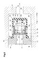
Fig. 2 is a cross-sectional view of the differential pressure control valve shown inFig. 1 ; -
Fig. 3 is a graph showing the relationship between the displacement amount of the valve body and urging force acting on the valve body in the differential pressure control valve shown inFig. 1 ; -
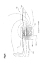
Fig. 4 is a diagram showing magnetic flux lines of the permanent magnet in the differential pressure control valve shown inFig. 1 ; -
Fig. 5 is a diagram showing magnetic flux lines of the permanent magnet in a differential pressure control valve according to a first comparison example; -
Fig. 6 is a diagram showing magnetic flux lines of the permanent magnet in a differential pressure control valve according to a second comparison example; -
Fig. 7 is a cross-sectional view illustrating a differential pressure control valve according to a second embodiment of the present invention; and -
Fig. 8 is a cross-sectional view illustrating a differential pressure control valve according to a third embodiment of the present invention. - First to third embodiments of the present invention will now be described with reference to the drawings.
- As shown in
Fig. 1 , a differentialpressure control valve 100 of a first embodiment functions as a check valve incorporated in a swash plate type variable displacement compressor (hereinafter, simply referred to as a compressor). The compressor includes acylinder block 1, in which a plurality ofparallel cylinder bores 1a are formed along a common circumference and at equal angular intervals. The compressor further includes a front housing member 3 and arear housing member 5, which are located forward of and rearward of thecylinder block 1, respectively. Thecylinder block 1 is held between the front housing member 3 and therear housing member 5 and is secured to the front housing member 3 and therear housing member 5 in this state. Acrank chamber 9 is formed inside thecylinder block 1 and the front housing member 3. In this description, the left side of the sheet ofFig. 1 is referred to as the front side, while the right side of the sheet is referred to as the rear side. The same applies toFigs. 2 and4 to 8 . - A
shaft hole 3a is formed in the front housing member 3, and ashaft hole 1b is formed in thecylinder block 1. Ashaft sealing device 9a and abearing device 9b are provided in theshaft hole 3a. A bearingdevice 9c is provided in theshaft hole 1 b. Adrive shaft 11 extends through theshaft holes cylinder block 1 via theshaft sealing device 9a and thebearing devices pulley 13 is rotatably supported by the front housing member 3 via abearing device 3b and is fixed to thedrive shaft 11. Abelt 13c, which is driven by an engine or motor of a vehicle, is engaged with thepulley 13. Thepulley 13 may be replaced by an electromagnetic clutch. - A
lug plate 15 is fitted about thedrive shaft 11 in thecrank chamber 9.Bearing devices 9d, 9e are located between thelug plate 15 and the front housing member 3. Thedrive shaft 11 extends through aswash plate 17. An inclinationangle decreasing spring 19 is provided between thelug plate 15 and theswash plate 17 and about thedrive shaft 11. The inclinationangle decreasing spring 19 urges theswash plate 17 in a direction decreasing the inclination angle of theswash plate 17. Asnap ring 11 a is fixed to a part of thedrive shaft 11 1 close to the rear end. A returningspring 21 is located between thesnap ring 11 a and theswash plate 17 and about thedrive shaft 11. The returningspring 21 urges theswash plate 17 in a direction opposite to direction in which the inclinationangle decreasing spring 19 urges theswash plate 17. Thelug plate 15 and theswash plate 17 are connected to each other by alink mechanism 23, which supports theswash plate 17 while allowing the inclination of theswash plate 17 to be variable. - A
reciprocating piston 25 is accommodated in each cylinder bore 1 a. A pair of front andrear shoes piston 25 and theswash plate 17. The pairs of theshoes swash plate 17 into reciprocation of thepistons 25. - A
valve unit 29 is located between thecylinder block 1 and therear housing member 5. In eachcylinder bore 1a, acompression chamber 31 is formed between thepiston 25 and thevalve unit 29. Asuction chamber 5a, which is located radially inward, and adischarge chamber 5b, which is located radially outward, are formed in therear housing 5. Refrigerant gas, which serves as a fluid for heat exchange, is supplied to thesuction chamber 5a. - When the
piston 25 is in the suction stroke, refrigerant gas in thesuction chamber 5a is drawn into thecompression chamber 31 through thevalve unit 29. When thepiston 25 is in the discharge stroke, the refrigerant gas in thecompression chamber 31 is compressed and discharged to thedischarge chamber 5b through thevalve unit 29. - The
crank chamber 9 and thesuction chamber 5a are connected to each other by ableed passage 42. Thecrank chamber 9 and thedischarge chamber 5b are connected to each other bysupply passages displacement control valve 2 is accommodated in therear housing 5. Thedisplacement control valve 2 is connected to thesuction chamber 5a by apressure introduction passage 48, and is connected to the crankchamber 9 and thedischarge chamber 5b by thesupply passages - When in operation, the
displacement control valve 2 changes the opening amount of thesupply passages suction chamber 5a, that is, the suction pressure). This changes the amount of refrigerant gas supplied from thedischarge chamber 5b to the crankchamber 9 via thesupply passages crank chamber 9 is adjusted to a desired pressure. As a result, the inclination angle of theswash plate 17 is changed, so that the displacement of the compressor is changed to a desired value. - A
discharge passage 50 is formed in therear housing member 5. Thedischarge passage 50 communicates with thedischarge chamber 5b and has anopening 5c located in the rear surface of therear housing member 5. When the compressor is installed in a vehicle air conditioner, the opening 5c is connected to a condenser (not shown). - As shown in
Fig. 2 in an enlarged manner, thedischarge passage 50 has alarge diameter portion 50a and asmall diameter portion 50b. The centers of the large andsmall diameter portions large diameter portion 50a is formed by recessing rearward the inner wall of thedischarge chamber 5b, and thesmall diameter portion 50b connects thelarge diameter portion 50a to theopening 5c (Fig. 1 ). The differentialpressure control valve 100 is arranged in thelarge diameter portion 50a. - The differential
pressure control valve 100 has avalve seat 110, avalve body 120, a guidingmember 130, and aspring 140. Thevalve seat 110, thevalve body 120, the guidingmember 130, and thespring 140 are assembled to be unitized and form the differentialpressure control valve 100. The differentialpressure control valve 100 is inserted into thelarge diameter portion 50a through thedischarge chamber 5b such that thevalve seat 110 contacts astep 50c and is prevented from coming off, for example, by a snap ring (not shown). In this manner, the differentialpressure control valve 100 is fixed in therear housing member 5 while separating thedischarge chamber 5b and thedischarge passage 50 from each other. Thedischarge chamber 5b is located upstream of thedischarge passage 50. A portion of thelarge diameter portion 50a that is on the opposite side of thevalve seat 110 to thedischarge chamber 5b is a downstream portion of thedischarge passage 50. - The
valve seat 110 includes abase 113 and acylindrical portion 114 located rearward of thebase 113. Thebase 113 is shaped as a thick disk the center of which is the axis X1. Thecylindrical portion 114 that is coaxial with thebase 113 has a smaller diameter than thebase 113. In this embodiment, thevalve seat 110 is made of iron (for example, S45C), which is magnetic material. - A
valve hole 111, the center of which is the axis X1, is formed through thebase 113 and thecylindrical portion 114. Thevalve hole 111 connects thedischarge chamber 5b to the downstream portion of thedischarge passage 50. As described below, the differentialpressure control valve 100 opens or closes thevalve hole 111 in accordance with the pressure difference between thedischarge chamber 5b or the upstream portion of thedischarge passage 50 and thedischarge passage 50. The end face of thecylindrical portion 114 that is located about thevalve hole 111 and faces rearward is aflat seating face 112. Theseating face 112 is parallel with a plane perpendicular to the axis X1. - The guiding
member 130 has acylindrical portion 133, the center of which is the axis X1, and adisk portion 134 that closes the rear end of thecylindrical portion 133. In this embodiment, the guidingmember 130 is made of resin, which is nonmagnetic material (for example, nylon resin). Afront end 133a of thecylindrical portion 133 is fitted from the outside to the outer circumferential surface of thecylindrical portion 114. The guidingmember 130 is thus fixed to thevalve seat 110. - The
cylindrical portion 133 has a plurality ofwindows 133b, which are located at a middle portion of thecylindrical portion 133 in the front-rear direction and aligned along the circumference about the axis X1. Thewindows 133b connect the interior of thecylindrical portion 133 to the outside. - The
valve body 120 is accommodated in the space surrounded by the cylindrical portion114 of thevalve seat 110 and the guidingmember 130, and is located downstream of thevalve seat 110 in thedischarge passage 50. Thevalve body 120 has alid 121 and a guidedmember 125. - The
lid 121 is shaped as a thin disk the center of which is the axis X1 and faces theseating face 112. In this embodiment, thelid 121 is made of iron (for example, S45C), which is a magnetic material. - The guided
member 125 is shaped as a cylinder the center of which is the axis X1. Afront opening 125a of the guidedmember 125 is fitted from outside to the outer edge of thelid 121. Accordingly, the guidedmember 125 and thelid 121 are integrated. In this embodiment, the guidedmember 125 is made of resin, which is nonmagnetic material (for example, nylon resin). - A clearance exists between the outer circumferential surface of the guided
member 125 and the inner circumferential surface of thecylindrical portion 133 to allow the guidedmember 125 to slide forward and rearward. Accordingly, thevalve body 120 can be displaced forward and backward while being guided by the guidingmember 130. When thevalve body 120 is displaced forward and contacts theseating face 112, thevalve body 120 is seated on thevalve seat 110 and closes thevalve hole 111. In this state, the guidedmember 125 closes thewindows 133b of thecylindrical portion 133. If thevalve body 120 is displaced rearward from this state, thevalve body 120 separates from thevalve seat 110 to open thevalve hole 111. In this state, the guidedmember 125 opens thewindows 133b. When thevalve body 120 is moved further rearward, and arear end 125c of the guidedmember 125 contacts thedisk portion 134, thevalve hole 111 is fully opened. In this state, the guidedmember 125 fully opens thewindows 133b. - An
inner flange 125d is formed on the inner circumferential surface of the guidedmember 125 at a middle position in the front-rear direction. Theinner flange 125d protrudes toward the axis X1. A holdingspace 125b for holding apermanent magnet 150 is formed between theinner flange 125d and thelid 121. - The
permanent magnet 150 is annular and its center is the axis X1, and is stuck to thelid 121 due to its own magnetic force. When thepermanent magnet 150 is inserted into the holdingspace 125b through theopening 125a, thelid 121 is fitted into theopening 125a. This holds thepermanent magnet 150 in the holdingspace 125b. Thepermanent magnet 150 is located on the opposite side of thelid 121 in relation to thevalve seat 110. That is, thepermanent magnet 150 is installed in a position that is away from (outside the area) the area in which thevalve body 120 is seated on or separates from thevalve seat 110. Thepermanent magnet 150 therefore does not contact thevalve seat 110. - In this embodiment, the
permanent magnet 150 is a samarium-cobalt magnet. The magnetic force of a samarium-cobalt magnet is slightly weaker than that of a neodymium magnet. However, the rate of change of the magnetic force of a samarium-cobalt magnet in relation to temperature, that is, the rate of decrease of the magnetic force in relation to increase in temperature is smaller than that of a neodymium magnet. Thus, a samarium-cobalt magnet has a superior heat resistance. Further, a samarium-cobalt magnet resists rust. Therefore, a samarium-cobalt magnet is suitable for the differentialpressure control valve 100, which is used in a vehicle air conditioner and is exposed to high-temperature refrigerant gas. - The
spring 140 is located between thevalve body 120 and the guidingmember 130. The front end of thespring 140 contacts thelid 121, and the rear end of thespring 140 is inserted in aspring holding portion 134a formed in thedisk portion 134. Compared to a spring used in a general differential pressure control valve, in which the valve body is urged toward the valve seat only by the urging force of the spring, thespring 140 is a small spring having a very small urging force. In this embodiment, thespring 140 is made of SUS316, which is nonmagnetic material. -
Fig. 3 shows the relationship between the amount of displacement of thevalve body 120 and a force urging thevalve body 120 toward thevalve seat 110 using solid lines S1, S2. Solid line S1 represents the relationship between the amount of displacement of thevalve body 120 and the magnetic force acting between thepermanent magnet 150 and thevalve seat 110. In this description, the magnetic force acting between thepermanent magnet 150 and thevalve seat 110 is referred to as a magnetic sticking force when the amount of displacement of thevalve body 120 is equal to zero (when thevalve body 120 is in contact with the valve seat 110). The magnetic force is referred to as a magnetic pulling force when the amount of displacement of thevalve body 120 is greater than zero (when thevalve body 120 is separated from the valve seat 110). - Solid line S2 shows an example of an urging force in a case of a general differential pressure control valve in which a valve body is urged toward a valve seat only by urging force of a spring. This example represents a differential pressure control valve that is obtained by removing the
permanent magnet 150 from the differentialpressure control valve 100 and replacing thespring 140 by a spring having a strong urging force. - In the case of the first embodiment, when the
valve hole 111 is closed, that is, when the amount of displacement of thevalve body 120 is zero, as represented by solid line S1, the magnetic sticking force acting between thepermanent magnet 150 and thevalve seat 110 is set to maintain contact between thevalve seat 110 and thevalve body 120 as long as the pressure difference between thedischarge chamber 5b and the downstream side of thedischarge passage 50 is less than or equal to a predetermined value ΔP. Also, as represented by solid line S2, the magnetic sticking force is equal to the force applied by the spring of a general differential pressure control valve that urges thevalve body 120 toward thevalve seat 110 when thevalve hole 111 is closed. - On the other hand, in a case of a general differential pressure control valve, when the
valve hole 111 is opened, that is, when the amount of displacement of thevalve body 120 is greater than zero, the force with which the spring urges thevalve body 120 toward thevalve seat 110 is proportionally increased as represented by solid line S2. - In contrast, in a case of the first embodiment, when the
valve hole 111 is opened, that is, when the amount of displacement of thevalve body 120 is greater than zero, the force acting between thepermanent magnet 150 and thevalve seat 110 sharply drops as represented by solid line S1. - When the compressor as described above is installed in a vehicle air conditioner, the
discharge chamber 5b is connected to the condenser (not shown) via thedischarge passage 50. The condenser is connected to an evaporator via an expansion valve, and the evaporator is connected to thesuction chamber 5a. When thedrive shaft 11 is rotated, for example, by an engine, the compressor introduces refrigerant gas from thesuction chamber 5a to thecompression chambers 31 to compress the refrigerant gas, and discharges the compressed refrigerant gas the displacement of which corresponds to the inclination angle of theswash plate 17, to thedischarge chamber 5b. - During this time, the
displacement control valve 2 is operated in accordance with a command for changing the temperature of air conditioning by an occupant or the speed of, for example, the vehicle engine. When the amount of refrigerant gas that is supplied from thedischarge chamber 5b to the crankchamber 9 via thesupply passages swash plate 17 is increased, which increases the displacement. In contrast, when the amount of refrigerant gas that is supplied from thedischarge chamber 5b to the crankchamber 9 via thesupply passages swash plate 17 is reduced, which reduces the displacement. Accordingly, the displacement of the compressor is changed as necessary. - The differential
pressure control valve 100 operates in the following manner. When the inclination angle of theswash plate 17 is minimized and the volume of refrigerant gas discharged from thedischarge chamber 5b (displacement) is minimized, the pressure difference between thedischarge chamber 5b and the downstream portion of thedischarge passage 50 becomes less than or equal to a predetermined pressure ΔP. Then, thevalve body 120 is moved toward the valve seat 110 (that is, in the direction approaching the valve seat 110) by the magnetic pulling force acting between thepermanent magnet 150 and thevalve seat 110 and a weak urging force of thespring 140 as shown inFig. 2 . Thevalve body 120 is eventually seated on thevalve seat 110, so that thelid 121 closes thevalve hole 111. This state is maintained by the magnetic sticking force acting between thepermanent magnet 150 and thevalve seat 110. As a result, thedischarge passage 50 is closed, so that circulation of refrigerant through the compressor, the condenser, the expansion valve, and the evaporator is stopped. This prevents refrigerant gas from flowing backward from thedischarge passage 50 to thedischarge chamber 5b. That is, the differentialpressure control valve 100 functions as a check valve. - On the other hand, when the inclination angle of the
swash plate 17 is increased from the minimum inclination angle, the displacement is increased accordingly, and the pressure difference between thedischarge chamber 5b and the downstream portion of thedischarge passage 50 exceeds a predetermined value ΔP. Then, the force produced by the pressure difference exceeds the magnetic sticking force acting between thepermanent magnet 150 and thevalve seat 110, and thelid 121 can no longer keep closing thevalve hole 111. As a result, thevalve body 120 is separated from thevalve seat 110 while being guided by the guidingmember 130. Since the magnetic pulling force acting between thepermanent magnet 150 and thevalve seat 110 sharply drops as represented by solid line S1, thelid 121 is pushed further by the refrigerant gas flowing through thevalve hole 111. Therefore, thevalve body 120 is largely separated from thevalve seat 110, so that the guidedmember 125 opens thewindows 133b. As a result, thedischarge passage 50 is quickly switched to the fully opened state, so that refrigerant gas discharged from thecompression chambers 31 to thedischarge chamber 5b flows to thedischarge passage 50. This starts circulation of refrigerant through the compressor, the condenser, the expansion valve, and the evaporator. - The differential
pressure control valve 100 according to the first embodiment has thepermanent magnet 150. As represented by solid lines S1, S2 inFig. 3 , the magnetic pulling force of thepermanent magnet 150 is weakened as thevalve body 120 is separated further away from thevalve seat 110. Thus, compared to a general differential pressure control valve, thevalve body 120 is easily separated from thevalve seat 110 when thevalve hole 111 is opened. Therefore, even if the pressure difference between thedischarge chamber 5b and the downstream portion of thedischarge passage 50 is small, the differentialpressure control valve 100 reliably opens thevalve hole 111, thereby reducing the pressure loss when refrigerant gas flows from thedischarge chamber 5b to the downstream portion of thedischarge passage 50 via thevalve hole 111. - Also, according to the differential
pressure control valve 100, thepermanent magnet 150 located in thelid 121 is installed in a position that is away from the area in which thevalve body 120 is seated on or separates from thevalve seat 110. Since thepermanent magnet 150 does not contact thevalve seat 110, thepermanent magnet 150 does not collide with thevalve seat 110 when thevalve hole 111 is closed. As a result, thepermanent magnet 150 is prevented from being cracked, and the durability of the differentialpressure control valve 100 is improved. - Further, according to the differential
pressure control valve 100, thevalve seat 110 and thelid 121 are made of magnetic material, and the guidingmember 130 and the guidedmember 125 are made of nonmagnetic material. Therefore, as shown inFig. 4 , the magnetic flux of thepermanent magnet 150 does not smoothly flow from thelid 121 toward the guidingmember 130 and the guidedmember 125, while smoothly flowing from thelid 121 toward thevalve seat 110. This further increases the magnetic flux density between thelid 121 and thevalve seat 110. InFig. 4 , phantom lines (two-dot chain lines) represent parts of thevalve seat 110, thevalve body 120, the guidingmember 130, and thepermanent magnet 150, and curves (solid lines) represent magnetic flux of thepermanent magnet 150. - On the other hand,
Fig. 5 shows a first comparative example. In the first comparative example, thelid 121 made of magnetic material and the guidedmember 125 made of nonmagnetic material are replaced by avalve body 120H that is formed by integrating a lid and a guided member, and made of magnetic material. In this example, most of the flux of thepermanent magnet 150 flows to thevalve body 120H, while little of the flux flows to thevalve seat 110. Therefore, compared to the case ofFig. 4 , the magnetic flux density between thelid 121 and thevalve seat 110 is significantly lowered. -
Fig. 6 shows a second comparative example. In the second comparative example, alid 121 H made of nonmagnetic material is used in place of thelid 121, which is made of magnetic material. That is, avalve body 1201 is entirely made of nonmagnetic material. In this example, since nonmagnetic material is located between thepermanent magnet 150 and thevalve seat 110, the magnetic flux of thepermanent magnet 150 does not smoothly flow to thevalve seat 110. Therefore, compared to the case ofFig. 4 , the magnetic flux density between thelid 121 and thevalve seat 110 is lowered. - As described above, compared to the first and second comparative examples, the magnetic flux density between the
lid 121 and thevalve seat 110 is higher in the differentialpressure control valve 100 of the first embodiment. This allows a great magnetic force to be generated between thelid 121 and thevalve seat 110, allowing smooth movement of thevalve body 120 toward thevalve seat 110, and thevalve body 120 to be stably seated on thevalve seat 110. Therefore, the size of thepermanent magnet 150 is permitted to be further reduced in the differentialpressure control valve 100, so that the space required for thepermanent magnet 150 can be small. This allows the overall size of the differentialpressure control valve 100 to be reduced. - Therefore, the differential
pressure control valve 100 of the first embodiment reduces the pressure loss, improves the durability, and reduces its size. The advantageous features of the differentialpressure control valve 100 allow pressure loss to be reduced and the durability to be improved in a variable displacement compressor equipped with the differentialpressure control valve 100. Also, the size of the compressor can be reduced. - The
permanent magnet 150 fixed to thelid 121 can be regarded as a weight that is displaced integrally with thevalve body 120. In this respect, thepermanent magnet 150 of the present embodiment can be reduced in size to reduce the weight of thevalve body 120. Thus, compared to the prior art shown above, the responsiveness of thevalve body 120 to the pressure difference between thedischarge chamber 5b and the downstream portion of thedischarge passage 50 is improved. - In the differential
pressure control valve 100 of this embodiment, the guidingmember 130 is made of resin, which is nonmagnetic material (for example, nylon resin). Therefore, as shown inFig. 4 , the magnetic flux of thepermanent magnet 150 does not smoothly flow from thelid 121 toward the guidingmember 130 and the guidedmember 125, while smoothly flowing from thelid 121 toward thevalve seat 110. Thus, the magnetic flux density between thelid 121 and thevalve seat 110 is higher in the differentialpressure control valve 100 of the first embodiment. This allows a great magnetic force to be generated between thelid 121 and thevalve seat 110, allowing smooth movement of thevalve body 120 toward thevalve seat 110, and thevalve body 120 to be stably seated on thevalve seat 110. Thepermanent magnet 150 of the differentialpressure control valve 100 can be reduced further in size, and the overall size of the differentialpressure control valve 100 is further reduced. - Further, the magnetic pulling force of the
permanent magnet 150 is weakened as thevalve body 120 is separated further away from thevalve seat 110, and the differentialpressure control valve 100 has thespring 140, which assists thepermanent magnet 150. Therefore, even if thevalve body 120 is largely separated from thevalve seat 110, and the magnetic pulling force of thepermanent magnet 150 is weakened, thespring 140 reliably causes thevalve body 120 to be seated on thevalve seat 110. Also, since the magnetic flux density is relatively high between thelid 121 and thevalve seat 110 in the differentialpressure control valve 100, the urging force of thespring 140 does not need to be significantly great. The size of thespring 140 can therefore be reduced. Further, since it is made of nonmagnetic material, thespring 140 reliably urges thevalve body 120 toward thevalve seat 110 without being influenced by thepermanent magnet 150. - The
permanent magnet 150 of the differentialpressure control valve 100 is coaxial with thevalve hole 111 and annular. Therefore, when thevalve hole 111 is closed, thepermanent magnet 150 approaches theseating face 112 around thevalve hole 111, so that the magnetic flux density between thevalve body 120 and thevalve seat 110 is further increased. Therefore, in the differentialpressure control valve 100, the magnetic force acting between thelid 121 and thevalve seat 110 is increased, and the size of thepermanent magnet 150 can be reduced further. Therefore, the size of the differentialpressure control valve 100 is further reduced, and the manufacture costs are further reduced. - Further, in the differential
pressure control valve 100, thelid 121 is fitted to theopening 125a with thepermanent magnet 150 held by the holdingspace 125b, so that thepermanent magnet 150 is fixed at a position downstream of thelid 121. Therefore, the assembly of the differentialpressure control valve 100 is more simplified than in a case where thepermanent magnet 150 is fixed to thelid 121, for example, with adhesive. In a case where thepermanent magnet 150 is fixed to thelid 121 with adhesive, the adhesive is degraded by high temperature, and thepermanent magnet 150 will possibly be separated from thelid 121. In the present embodiment, however, thepermanent magnet 150 is not severely influenced by high temperatures. This improves the durability. - As shown in
Fig. 7 , a differentialpressure control valve 200 according to the second embodiment has apermanent magnet 250 fixed to thevalve seat 110 in place of thepermanent magnet 150 used in the differentialpressure control valve 100 of the first embodiment. Also, thespring 140 is omitted. The other structures are the same as the differentialpressure control valve 100 according to the first embodiment. Thus, like or the same reference numerals are given to those components that are like or the same as the corresponding components of the first embodiment and detailed explanations are omitted. - A
step 114a, which is formed by increasing the diameter of thevalve hole 111, is formed at one end of thecylindrical portion 114 that is close to theseating face 112. - An annular
permanent magnet 250, the center of which is the axis X1, is attached to thestep 114a. Thepermanent magnet 250 is stuck to thevalve seat 110 due to the own magnetic force. The rear facingend face 250a of thepermanent magnet 250 is located forward of and separated from theseating face 112. That is, thepermanent magnet 250 is installed in a position that is away from the area in which thevalve body 120 is seated on or separates from thevalve seat 110. Thepermanent magnet 250 therefore does not contact thelid 121. Also, anescape portion 121a is recessed in thelid 121 to create a large clearance between thelid 121 and theend face 250a of thepermanent magnet 250. - The differential
pressure control valve 200 is capable of, using the magnetic force acting between thepermanent magnet 250 and thelid 121, selectively opening and closing thevalve hole 111 by operating in the same manner as the differentialpressure control valve 100 of the first embodiment. At this, the differentialpressure control valve 200 achieves the same advantages as the differentialpressure control valve 100 of the first embodiment. - Also, the differential
pressure control valve 200 has no spring that urges thevalve body 120 toward thevalve seat 110. Thus, thevalve body 120 is urged toward thevalve seat 110 only by the magnetic pulling force acting between thepermanent magnet 250 and thelid 121. This eliminates the necessity for a spring in the differentialpressure control valve 200, and reduces the components and simplifies the assembly. - In the differential
pressure control valve 200, thepermanent magnet 250 is fixed to thevalve seat 110 at a position away from theseating face 112 around thevalve hole 111. When magnetic foreign material is contained refrigerant gas, such material can be stuck to thepermanent magnet 250. At this time, the material is stuck to a part away from theseating face 112, for example, to theend face 250a, the material is prevented from caught onto theseating face 112. If a large foreign object is stuck onto theend face 250a, it is held in the large clearance between theend face 250a and theescape portion 121 a, and full closure of thevalve hole 111 is not hindered by such a foreign object. As a result, thevalve hole 111 is reliably closed in the differentialpressure control valve 200. - As shown in
Fig. 8 , a differentialpressure control valve 300 according to the third embodiment has apermanent magnet 350 fixed to thevalve seat 110 in place of thepermanent magnet 150 used in the differentialpressure control valve 100 of the first embodiment. Also, thespring 140 is omitted. The other structures are the same as the differentialpressure control valve 100 according to the first embodiment. Thus, like or the same reference numerals are given to those components that are like or the same as the corresponding components of the first embodiment and detailed explanations are omitted. - A
step 114b, which is formed by decreasing the diameter of the outer circumferential surface of thecylindrical portion 114, is formed at one end of thecylindrical portion 114 that is close to theseating face 112. - An annular
permanent magnet 350, the center of which is the axis X1, is attached to thestep 114b. Thepermanent magnet 350 is stuck to thevalve seat 110 due to the own magnetic force. The rear facingend face 350a of thepermanent magnet 350 is located forward of and separated from theseating face 112. That is, thepermanent magnet 350 is installed in a position that is away from the area in which thevalve body 120 is seated on or separates from thevalve seat 110. Thepermanent magnet 350 therefore does not contact thelid 121. Also, anescape portion 121b is recessed in thelid 121 and the guidedmember 125 to create a large clearance between theend face 350a of thepermanent magnet 350 and a surface defined by thelid 121 and the guidedmember 125. - The differential
pressure control valve 300 is capable of using the magnetic force acting between thepermanent magnet 350 and thelid 121 for selectively opening and closing thevalve hole 111 by operating in the same manner as the differentialpressure control valves - The difference between the differential
pressure control valve 300 of the third embodiment and the differentialpressure control valve 200 of the second embodiment is whether or not thepermanent magnet seating face 112 or radially outward of theseating face 112. Therefore, the differentialpressure control valve 300 of the third embodiment has the same advantages as the differentialpressure control valve 200 of the second embodiment. - So far, the present invention has been described with reference to the first to third embodiments. However, the present invention is not to be limited to these embodiments, but can be modified within the scope of the invention as follows.
- For example, the differential
pressure control valves rear housing member 5. - In the above embodiments, the magnetic material that forms the
valve seat 110 and thelid 121 is S45C, which is high-carbon steel. Instead, iron-based material such as chromium molybdenum steel, for example, SCM435 and SCM440, and martensite stainless steel may be used. In the illustrated embodiments, the nonmagnetic material forming the guidedmember 125 is, for example, nylon resin. However, other resin or aluminum based material may be used. - In the illustrated embodiments, the
spring 140 is made of SUS316. However, thespring 140 may be made of nonmagnetic material such as resin or FRP. - In the illustrated embodiments, the
permanent magnet 150 is annular and coaxial with thevalve hole 111. However, thepermanent magnet 150 may be columnar and coaxial with thevalve hole 111. - In the above illustrated embodiments, the
permanent magnet 150 is a samarium-cobalt magnet. In place of this, (1) a ferrite magnet such as a barium ferrite magnet and a strontium ferrite magnet, (2) a metal magnet such as an alnico magnet and a rare-earth magnet, or (3) a bond magnet such as a rubber magnet and a plastic magnet may be used. As the rare-earth magnet, a neodymium magnet may be used instead of a samarium-cobalt magnet such as a 1-5 series magnet and a 1-17 series magnet. As a rubber magnet, a ferrite rubber magnet or a neodymium rubber magnet may be used. As a plastic magnet, a ferrite plastic magnet or a neodymium plastic magnet may be used. - The
permanent magnet 150 may be fixed to thelid 121 or thevalve seat 110 using adhesive. - The present invention may be used in an air conditioning apparatus.
- A differential pressure control valve has a valve seat, a valve body, and a guiding member. A valve hole through which fluid passes is formed in the valve seat. The valve body is located on the downstream side of the valve seat, and separates from or is seated on the valve seat in accordance with the pressure difference between the upstream side and the downstream side to selectively open and close the valve hole. The guiding member is fixed to the valve seat to guide the valve body. The valve seat is made of magnetic material. The valve body has a lid made of magnetic material and a guided member made of nonmagnetic material. The lid is seated on the valve seat to close the valve hole, and the guided member is guided by the guiding member. One of the valve seat and the lid has a permanent magnet. The valve body is urged in the direction approaching the valve seat by the magnetic pulling force of the permanent magnet. The permanent magnet is located at a position outside the area in which the valve body is seated on the valve seat.
Claims (9)
- A differential pressure control valve (100), comprising:a valve seat (110) having a valve hole (111) through which fluid passes;a valve body (120) located downstream of the valve seat, the valve body separating from or being seated on the valve seat in accordance with the pressure difference between the upstream side and the downstream side, thereby opening or closing the valve hole; anda guiding member (130) fixed to the valve seat to guide the valve body, whereinthe valve seat (110) is made of magnetic material,the valve body (120) has a lid (121) made of magnetic material and a guided member (125) made of nonmagnetic material, the lid (121) being seatable on the valve seat to close the valve hole, and the guided member (125) being guided by the guiding member,one of the valve seat and the lid has a permanent magnet (150), the valve body being urged in the direction approaching the valve seat by the magnetic pulling force of the permanent magnet, andthe permanent magnet is located at a position outside an area in which the valve body is seated on the valve seat.
- The differential pressure control valve according to claim 1, wherein the guiding member is made of nonmagnetic material.
- The differential pressure control valve according to claim 1 or 2, further comprising a spring (140) for urging the valve body toward the valve seat.
- The differential pressure control valve according to any one of claims 1 to 3,
wherein the permanent magnet is annular and coaxial with the valve hole. - The differential pressure control valve according to claim 4, wherein the permanent magnet is fixed to the valve seat at a position away from a seating face around the valve hole.
- The differential pressure control valve according to any one of claims 1 to 4,
wherein the permanent magnet is located at a position on the opposite side of the lid in relation to the valve seat. - The differential pressure control valve according to any one of claims 1 to 6,
wherein
the guided member has an opening (125a) to which the lid is fitted and a holding space (125b) that is connected to the opening and holds the permanent magnet, and
the lid is fitted to the opening with the permanent magnet held in the holding space, so that the permanent magnet is fixed to the lid. - The differential pressure control valve according to any one of claims 1 to 7,
wherein the permanent magnet is a samarium-cobalt magnet. - A variable displacement compressor comprising a compression chamber (31) and a discharge chamber (5b), the compressor capable of compressing fluid drawing into the compression chamber and discharging the fluid to the discharge chamber, and varying the displacement of the fluid discharged from the compression chamber to the discharge chamber, the compressor further comprising
the differential pressure control valve (100) according to any one of claims 1 to 8, the differential pressure control valve (100) being arranged in the discharge chamber or in a discharge passage (50) that communicates with the discharge chamber.
Applications Claiming Priority (1)
| Application Number | Priority Date | Filing Date | Title |
|---|---|---|---|
| JP2010261876A JP5429143B2 (en) | 2010-11-25 | 2010-11-25 | Differential pressure control valve and variable capacity compressor |
Publications (1)
| Publication Number | Publication Date |
|---|---|
| EP2458211A1 true EP2458211A1 (en) | 2012-05-30 |
Family
ID=45444397
Family Applications (1)
| Application Number | Title | Priority Date | Filing Date |
|---|---|---|---|
| EP11190053A Withdrawn EP2458211A1 (en) | 2010-11-25 | 2011-11-22 | Differential pressure control valve and variable displacement compressor having the differential pressure control valve |
Country Status (6)
| Country | Link |
|---|---|
| US (1) | US9145888B2 (en) |
| EP (1) | EP2458211A1 (en) |
| JP (1) | JP5429143B2 (en) |
| KR (1) | KR101300638B1 (en) |
| CN (1) | CN102537451B (en) |
| BR (1) | BRPI1105762A2 (en) |
Cited By (5)
| Publication number | Priority date | Publication date | Assignee | Title |
|---|---|---|---|---|
| CN103244498A (en) * | 2013-05-17 | 2013-08-14 | 浙江科技学院 | Precision pressure regulating type direct-acting overflow valve |
| EP2930409A1 (en) * | 2014-04-08 | 2015-10-14 | Yokogawa Electric Corporation | Apparatus and methods for passive pressure modulation |
| EP3118498A1 (en) * | 2015-07-17 | 2017-01-18 | MAN Truck & Bus AG | Ventilation and/or pressure limiting valve |
| US9746375B2 (en) | 2014-04-08 | 2017-08-29 | Yokogawa Electric Corporation | Systems, methods, and apparatus for optical noise management in optical spectroscopy |
| KR20180110620A (en) * | 2017-03-29 | 2018-10-10 | 가부시키가이샤 도요다 지도숏키 | Compressor |
Families Citing this family (18)
| Publication number | Priority date | Publication date | Assignee | Title |
|---|---|---|---|---|
| US8684331B2 (en) * | 2011-05-11 | 2014-04-01 | Bioflo, Llc | Valve for regulating the flow of a liquid |
| US20130221255A1 (en) * | 2012-02-29 | 2013-08-29 | Vernay Laboratories, Inc. | Magneto-rheological elastomeric fluid control armature assembly |
| JP6119429B2 (en) * | 2013-05-29 | 2017-04-26 | スズキ株式会社 | Fluid discharge device |
| CA2851634C (en) | 2014-05-09 | 2022-05-03 | 1773915 Alberta Ltd. | Method of gas lift in wells experiencing hydrostatic loading |
| KR102040969B1 (en) * | 2014-10-06 | 2019-11-06 | 한온시스템 주식회사 | Control device for compression amount of swash plate type compressor |
| US10712022B2 (en) * | 2015-10-20 | 2020-07-14 | A. O. Smith Corporation | Constant pressure switch apparatus and water heating system |
| JP2017115944A (en) * | 2015-12-22 | 2017-06-29 | アイシン精機株式会社 | Flow control valve |
| JP2017115943A (en) * | 2015-12-22 | 2017-06-29 | アイシン精機株式会社 | Flow control valve, and vehicle engine cooling apparatus including the flow control valve |
| KR20180102391A (en) * | 2017-03-07 | 2018-09-17 | 한온시스템 주식회사 | Discharge valve and compressor having the same |
| JP7162435B2 (en) * | 2018-03-23 | 2022-10-28 | トリニティ工業株式会社 | valve device |
| CN108869267B (en) * | 2018-07-10 | 2019-06-28 | 燕山大学 | The automatic cone valve of mangneto variable rate spring reciprocating pump |
| US10662737B2 (en) * | 2018-07-24 | 2020-05-26 | Baker Hughes, A Ge Company, Llc | Fluid injection valve |
| CN109323024B (en) * | 2018-11-26 | 2019-11-05 | 中国航发沈阳黎明航空发动机有限责任公司 | A kind of device adjusted suitable for high temperature, high pressure gas pulsation |
| CN111895165B (en) * | 2019-05-05 | 2024-07-19 | 得立鼎工业株式会社 | Valve device |
| US11885431B2 (en) | 2019-09-17 | 2024-01-30 | Trinity Industrial Corporation | Valve module, valve device, valve system |
| CN114607811B (en) * | 2020-12-09 | 2024-10-29 | 中国石油天然气股份有限公司 | High pressure check valve |
| DE202021103675U1 (en) * | 2021-07-08 | 2022-10-13 | Liquitec Ag | Magnetic check valve |
| KR102704350B1 (en) * | 2022-07-19 | 2024-09-09 | 이우종 | Urethane tube integrated air valve |
Citations (7)
| Publication number | Priority date | Publication date | Assignee | Title |
|---|---|---|---|---|
| US4808089A (en) * | 1986-09-01 | 1989-02-28 | Siemens Aktiengesellschaft | Reciprocating pump for a medication administering device |
| JP2000055223A (en) | 1998-08-07 | 2000-02-22 | Toyota Autom Loom Works Ltd | Differential pressure control valve and compressor |
| EP1096188A2 (en) * | 1999-10-29 | 2001-05-02 | The BOC Group plc | Relief valve |
| US20040062660A1 (en) * | 2001-01-29 | 2004-04-01 | Yukio Kazahaya | Variable displacement type swash plate clutch-less compressor |
| GB2416822A (en) * | 2004-08-06 | 2006-02-08 | Boc Group Plc | Inlet valve for vacuum pump |
| DE102006006627B3 (en) * | 2006-02-09 | 2007-07-12 | Iav Gmbh Ingenieurgesellschaft Auto Und Verkehr | check valve |
| WO2008011240A2 (en) * | 2006-07-20 | 2008-01-24 | Fleetguard, Inc. | Magnetic check valve |
Family Cites Families (13)
| Publication number | Priority date | Publication date | Assignee | Title |
|---|---|---|---|---|
| US2949931A (en) * | 1958-01-29 | 1960-08-23 | Hughes Aircraft Co | Magnetic check valve |
| US4275759A (en) * | 1979-05-29 | 1981-06-30 | Huang Shih C | Closure member |
| JPH0452135Y2 (en) * | 1986-02-17 | 1992-12-08 | ||
| FR2727736B1 (en) * | 1994-12-02 | 1997-01-24 | Eaton Sa Monaco | VALVE CONTROLLED BY A FLUID |
| US6408913B1 (en) * | 1998-02-19 | 2002-06-25 | Pirelli Pneumatici S.P.A. | Device for inflating and deflating a tire inner tube, inner tube and wheel formed by a tire and a rim inside which the inner tube is arranged |
| US6352416B1 (en) | 1999-03-15 | 2002-03-05 | Kabushiki Kaisha Toyoda Jidoshokki Seisakusho | Device and method for controlling displacement of variable displacement compressor |
| JP3549501B2 (en) * | 2001-07-23 | 2004-08-04 | カネキタ株式会社 | Air pulser and device using the air pulser |
| JP2005265107A (en) * | 2004-03-19 | 2005-09-29 | Toyota Industries Corp | Check valve |
| JP2005351207A (en) | 2004-06-11 | 2005-12-22 | Tgk Co Ltd | Control valve for variable displacement compressor |
| JP2007247512A (en) * | 2006-03-15 | 2007-09-27 | Toyota Industries Corp | Capacity control valve in variable capacity type compressor |
| JP2008014459A (en) * | 2006-07-07 | 2008-01-24 | Olympus Imaging Corp | Fluid control device and fuel cell system |
| EP2182531B1 (en) * | 2008-10-29 | 2014-01-08 | Sauer-Danfoss ApS | Valve actuator |
| JP2010185469A (en) * | 2009-02-10 | 2010-08-26 | Nippon Pneumatic Mfg Co Ltd | Control valve and air hammer |
-
2010
- 2010-11-25 JP JP2010261876A patent/JP5429143B2/en not_active Expired - Fee Related
-
2011
- 2011-11-16 KR KR1020110119430A patent/KR101300638B1/en not_active Expired - Fee Related
- 2011-11-22 US US13/302,558 patent/US9145888B2/en not_active Expired - Fee Related
- 2011-11-22 EP EP11190053A patent/EP2458211A1/en not_active Withdrawn
- 2011-11-22 CN CN201110373300.0A patent/CN102537451B/en not_active Expired - Fee Related
- 2011-11-23 BR BRPI1105762-9A patent/BRPI1105762A2/en not_active IP Right Cessation
Patent Citations (7)
| Publication number | Priority date | Publication date | Assignee | Title |
|---|---|---|---|---|
| US4808089A (en) * | 1986-09-01 | 1989-02-28 | Siemens Aktiengesellschaft | Reciprocating pump for a medication administering device |
| JP2000055223A (en) | 1998-08-07 | 2000-02-22 | Toyota Autom Loom Works Ltd | Differential pressure control valve and compressor |
| EP1096188A2 (en) * | 1999-10-29 | 2001-05-02 | The BOC Group plc | Relief valve |
| US20040062660A1 (en) * | 2001-01-29 | 2004-04-01 | Yukio Kazahaya | Variable displacement type swash plate clutch-less compressor |
| GB2416822A (en) * | 2004-08-06 | 2006-02-08 | Boc Group Plc | Inlet valve for vacuum pump |
| DE102006006627B3 (en) * | 2006-02-09 | 2007-07-12 | Iav Gmbh Ingenieurgesellschaft Auto Und Verkehr | check valve |
| WO2008011240A2 (en) * | 2006-07-20 | 2008-01-24 | Fleetguard, Inc. | Magnetic check valve |
Cited By (5)
| Publication number | Priority date | Publication date | Assignee | Title |
|---|---|---|---|---|
| CN103244498A (en) * | 2013-05-17 | 2013-08-14 | 浙江科技学院 | Precision pressure regulating type direct-acting overflow valve |
| EP2930409A1 (en) * | 2014-04-08 | 2015-10-14 | Yokogawa Electric Corporation | Apparatus and methods for passive pressure modulation |
| US9746375B2 (en) | 2014-04-08 | 2017-08-29 | Yokogawa Electric Corporation | Systems, methods, and apparatus for optical noise management in optical spectroscopy |
| EP3118498A1 (en) * | 2015-07-17 | 2017-01-18 | MAN Truck & Bus AG | Ventilation and/or pressure limiting valve |
| KR20180110620A (en) * | 2017-03-29 | 2018-10-10 | 가부시키가이샤 도요다 지도숏키 | Compressor |
Also Published As
| Publication number | Publication date |
|---|---|
| US20120134854A1 (en) | 2012-05-31 |
| BRPI1105762A2 (en) | 2013-05-28 |
| US9145888B2 (en) | 2015-09-29 |
| CN102537451A (en) | 2012-07-04 |
| KR20120056771A (en) | 2012-06-04 |
| JP5429143B2 (en) | 2014-02-26 |
| JP2012112449A (en) | 2012-06-14 |
| KR101300638B1 (en) | 2013-08-27 |
| CN102537451B (en) | 2015-07-08 |
Similar Documents
| Publication | Publication Date | Title |
|---|---|---|
| US9145888B2 (en) | Differential pressure control valve and variable displacement compressor having the differential pressure control valve | |
| CN110114573B (en) | volume control valve | |
| EP3822485B1 (en) | Capacity control valve | |
| EP2857681B1 (en) | Volume control valve | |
| EP1059444B1 (en) | Variable capacity compressor with check valve with damper | |
| US8251673B2 (en) | Displacement control valve of a variable displacement compressor | |
| US20070264134A1 (en) | Control valve for variable displacement compressor | |
| EP3889430A1 (en) | Capacity control valve | |
| WO2019131693A1 (en) | Capacity control valve and method for controlling same | |
| JP4066563B2 (en) | Check valve | |
| EP1696123B1 (en) | Variable displacement compressor | |
| US6927656B2 (en) | Electromagnetic actuator and method for manufacturing electromagnetic actuator, and control valve for variable displacement compressor using electromagnetic actuator | |
| US20080006331A1 (en) | Differential pressure valve | |
| EP1059446A2 (en) | Variable capacity type compressor with check valve | |
| EP1852607A1 (en) | Variable capacity swash plate type compressor | |
| US6783332B2 (en) | Control valve of variable displacement compressor with pressure sensing member | |
| US20110020147A1 (en) | Swash plate type compressor | |
| JP7625357B2 (en) | valve | |
| JPH0735874U (en) | solenoid valve | |
| US12264743B2 (en) | Fluid control valve | |
| US12297913B2 (en) | Fluid control valve | |
| US20060120883A1 (en) | Displacement control valve of a variable displacement swash plate | |
| WO2019142930A1 (en) | Capacity control valve and control method of capacity control valve | |
| JPH07259765A (en) | Compressor |
Legal Events
| Date | Code | Title | Description |
|---|---|---|---|
| PUAI | Public reference made under article 153(3) epc to a published international application that has entered the european phase |
Free format text: ORIGINAL CODE: 0009012 |
|
| 17P | Request for examination filed |
Effective date: 20111122 |
|
| AK | Designated contracting states |
Kind code of ref document: A1 Designated state(s): AL AT BE BG CH CY CZ DE DK EE ES FI FR GB GR HR HU IE IS IT LI LT LU LV MC MK MT NL NO PL PT RO RS SE SI SK SM TR |
|
| AX | Request for extension of the european patent |
Extension state: BA ME |
|
| 17Q | First examination report despatched |
Effective date: 20130801 |
|
| GRAP | Despatch of communication of intention to grant a patent |
Free format text: ORIGINAL CODE: EPIDOSNIGR1 |
|
| RIC1 | Information provided on ipc code assigned before grant |
Ipc: F16K 31/08 20060101ALI20180716BHEP Ipc: F04B 27/18 20060101ALI20180716BHEP Ipc: F04B 53/10 20060101ALI20180716BHEP Ipc: F04B 11/00 20060101ALI20180716BHEP Ipc: F16K 15/02 20060101AFI20180716BHEP Ipc: F04B 49/22 20060101ALI20180716BHEP Ipc: F04B 27/22 20060101ALI20180716BHEP |
|
| INTG | Intention to grant announced |
Effective date: 20180810 |
|
| STAA | Information on the status of an ep patent application or granted ep patent |
Free format text: STATUS: THE APPLICATION IS DEEMED TO BE WITHDRAWN |
|
| 18D | Application deemed to be withdrawn |
Effective date: 20181221 |