EP2458175A2 - Nose cone assembly - Google Patents
Nose cone assembly Download PDFInfo
- Publication number
- EP2458175A2 EP2458175A2 EP11188017A EP11188017A EP2458175A2 EP 2458175 A2 EP2458175 A2 EP 2458175A2 EP 11188017 A EP11188017 A EP 11188017A EP 11188017 A EP11188017 A EP 11188017A EP 2458175 A2 EP2458175 A2 EP 2458175A2
- Authority
- EP
- European Patent Office
- Prior art keywords
- nose cone
- support ring
- load spreader
- cone assembly
- resilient attachment
- Prior art date
- Legal status (The legal status is an assumption and is not a legal conclusion. Google has not performed a legal analysis and makes no representation as to the accuracy of the status listed.)
- Withdrawn
Links
- 229910052799 carbon Inorganic materials 0.000 claims description 10
- 239000003365 glass fiber Substances 0.000 claims description 10
- OKTJSMMVPCPJKN-UHFFFAOYSA-N Carbon Chemical compound [C] OKTJSMMVPCPJKN-UHFFFAOYSA-N 0.000 claims description 9
- 239000000835 fiber Substances 0.000 claims description 9
- 239000002131 composite material Substances 0.000 claims description 5
- 239000007769 metal material Substances 0.000 claims description 2
- 229910000831 Steel Inorganic materials 0.000 description 7
- 239000010959 steel Substances 0.000 description 7
- 238000004519 manufacturing process Methods 0.000 description 6
- 239000000945 filler Substances 0.000 description 4
- 238000010276 construction Methods 0.000 description 3
- 230000000694 effects Effects 0.000 description 3
- 229910000838 Al alloy Inorganic materials 0.000 description 2
- 239000004593 Epoxy Substances 0.000 description 2
- 229910052782 aluminium Inorganic materials 0.000 description 2
- XAGFODPZIPBFFR-UHFFFAOYSA-N aluminium Chemical compound [Al] XAGFODPZIPBFFR-UHFFFAOYSA-N 0.000 description 2
- 230000032798 delamination Effects 0.000 description 2
- 230000003628 erosive effect Effects 0.000 description 2
- 238000009787 hand lay-up Methods 0.000 description 2
- 238000003754 machining Methods 0.000 description 2
- 239000000463 material Substances 0.000 description 2
- 238000000034 method Methods 0.000 description 2
- 229920005989 resin Polymers 0.000 description 2
- 239000011347 resin Substances 0.000 description 2
- 230000000717 retained effect Effects 0.000 description 2
- RTAQQCXQSZGOHL-UHFFFAOYSA-N Titanium Chemical compound [Ti] RTAQQCXQSZGOHL-UHFFFAOYSA-N 0.000 description 1
- 239000004411 aluminium Substances 0.000 description 1
- 230000000712 assembly Effects 0.000 description 1
- 238000000429 assembly Methods 0.000 description 1
- 238000005452 bending Methods 0.000 description 1
- 150000001721 carbon Chemical class 0.000 description 1
- 238000005336 cracking Methods 0.000 description 1
- 238000006073 displacement reaction Methods 0.000 description 1
- 230000009977 dual effect Effects 0.000 description 1
- 239000003822 epoxy resin Substances 0.000 description 1
- 239000004744 fabric Substances 0.000 description 1
- 238000009730 filament winding Methods 0.000 description 1
- 238000005242 forging Methods 0.000 description 1
- 239000011521 glass Substances 0.000 description 1
- 238000009863 impact test Methods 0.000 description 1
- 230000013011 mating Effects 0.000 description 1
- 229910052751 metal Inorganic materials 0.000 description 1
- 239000002184 metal Substances 0.000 description 1
- 150000002739 metals Chemical class 0.000 description 1
- 239000003973 paint Substances 0.000 description 1
- 239000004033 plastic Substances 0.000 description 1
- 229920003023 plastic Polymers 0.000 description 1
- 229920000647 polyepoxide Polymers 0.000 description 1
- 239000004814 polyurethane Substances 0.000 description 1
- 229920002635 polyurethane Polymers 0.000 description 1
- 229910001220 stainless steel Inorganic materials 0.000 description 1
- 238000004227 thermal cracking Methods 0.000 description 1
- 239000010936 titanium Substances 0.000 description 1
- 229910052719 titanium Inorganic materials 0.000 description 1
- 238000009736 wetting Methods 0.000 description 1
Images


Classifications
-
- F—MECHANICAL ENGINEERING; LIGHTING; HEATING; WEAPONS; BLASTING
- F02—COMBUSTION ENGINES; HOT-GAS OR COMBUSTION-PRODUCT ENGINE PLANTS
- F02K—JET-PROPULSION PLANTS
- F02K3/00—Plants including a gas turbine driving a compressor or a ducted fan
- F02K3/02—Plants including a gas turbine driving a compressor or a ducted fan in which part of the working fluid by-passes the turbine and combustion chamber
- F02K3/04—Plants including a gas turbine driving a compressor or a ducted fan in which part of the working fluid by-passes the turbine and combustion chamber the plant including ducted fans, i.e. fans with high volume, low pressure outputs, for augmenting the jet thrust, e.g. of double-flow type
- F02K3/06—Plants including a gas turbine driving a compressor or a ducted fan in which part of the working fluid by-passes the turbine and combustion chamber the plant including ducted fans, i.e. fans with high volume, low pressure outputs, for augmenting the jet thrust, e.g. of double-flow type with front fan
-
- B—PERFORMING OPERATIONS; TRANSPORTING
- B64—AIRCRAFT; AVIATION; COSMONAUTICS
- B64C—AEROPLANES; HELICOPTERS
- B64C11/00—Propellers, e.g. of ducted type; Features common to propellers and rotors for rotorcraft
- B64C11/02—Hub construction
- B64C11/14—Spinners
-
- F—MECHANICAL ENGINEERING; LIGHTING; HEATING; WEAPONS; BLASTING
- F02—COMBUSTION ENGINES; HOT-GAS OR COMBUSTION-PRODUCT ENGINE PLANTS
- F02C—GAS-TURBINE PLANTS; AIR INTAKES FOR JET-PROPULSION PLANTS; CONTROLLING FUEL SUPPLY IN AIR-BREATHING JET-PROPULSION PLANTS
- F02C7/00—Features, components parts, details or accessories, not provided for in, or of interest apart form groups F02C1/00 - F02C6/00; Air intakes for jet-propulsion plants
- F02C7/04—Air intakes for gas-turbine plants or jet-propulsion plants
-
- F—MECHANICAL ENGINEERING; LIGHTING; HEATING; WEAPONS; BLASTING
- F03—MACHINES OR ENGINES FOR LIQUIDS; WIND, SPRING, OR WEIGHT MOTORS; PRODUCING MECHANICAL POWER OR A REACTIVE PROPULSIVE THRUST, NOT OTHERWISE PROVIDED FOR
- F03D—WIND MOTORS
- F03D1/00—Wind motors with rotation axis substantially parallel to the air flow entering the rotor
- F03D1/06—Rotors
- F03D1/065—Rotors characterised by their construction elements
- F03D1/0691—Rotors characterised by their construction elements of the hub
-
- F—MECHANICAL ENGINEERING; LIGHTING; HEATING; WEAPONS; BLASTING
- F05—INDEXING SCHEMES RELATING TO ENGINES OR PUMPS IN VARIOUS SUBCLASSES OF CLASSES F01-F04
- F05B—INDEXING SCHEME RELATING TO WIND, SPRING, WEIGHT, INERTIA OR LIKE MOTORS, TO MACHINES OR ENGINES FOR LIQUIDS COVERED BY SUBCLASSES F03B, F03D AND F03G
- F05B2280/00—Materials; Properties thereof
- F05B2280/50—Intrinsic material properties or characteristics
- F05B2280/5001—Elasticity
-
- F—MECHANICAL ENGINEERING; LIGHTING; HEATING; WEAPONS; BLASTING
- F05—INDEXING SCHEMES RELATING TO ENGINES OR PUMPS IN VARIOUS SUBCLASSES OF CLASSES F01-F04
- F05D—INDEXING SCHEME FOR ASPECTS RELATING TO NON-POSITIVE-DISPLACEMENT MACHINES OR ENGINES, GAS-TURBINES OR JET-PROPULSION PLANTS
- F05D2300/00—Materials; Properties thereof
- F05D2300/50—Intrinsic material properties or characteristics
- F05D2300/501—Elasticity
-
- Y—GENERAL TAGGING OF NEW TECHNOLOGICAL DEVELOPMENTS; GENERAL TAGGING OF CROSS-SECTIONAL TECHNOLOGIES SPANNING OVER SEVERAL SECTIONS OF THE IPC; TECHNICAL SUBJECTS COVERED BY FORMER USPC CROSS-REFERENCE ART COLLECTIONS [XRACs] AND DIGESTS
- Y02—TECHNOLOGIES OR APPLICATIONS FOR MITIGATION OR ADAPTATION AGAINST CLIMATE CHANGE
- Y02E—REDUCTION OF GREENHOUSE GAS [GHG] EMISSIONS, RELATED TO ENERGY GENERATION, TRANSMISSION OR DISTRIBUTION
- Y02E10/00—Energy generation through renewable energy sources
- Y02E10/70—Wind energy
- Y02E10/72—Wind turbines with rotation axis in wind direction
Definitions
- the present invention relates to a nose cone assembly for a gas turbine engine.
- a nose cone assembly is typically found at the intake of a gas turbine engine.
- the assembly conventionally comprises a one or two piece nose cone mounted on a support ring that is in turn fixed to the fan disk.
- the purpose of the nose cone assembly is to provide smooth inflow of air to the fan blades and to protect the rest of the engine from damage that could be caused by a foreign body impact such as a bird strike.
- a typical two piece nose cone assembly 2 is illustrated in Figure 1 .
- the nose cone 4 comprises a woven glass fibre fabric pre-impregnated with an epoxy based resin and is manufactured using a hand lay-up technique.
- the thickness of the nose cone 4 and the cone angle are determined by the required impact behaviour.
- the thickness of the nose cone 4 is determined empirically based on impact test experience and increases with radius.
- the angle of the nose cone 4 is determined according to both impact behaviour and the necessity to avoid ice build up on the surface of the nose cone 4.
- the outer surfaces 6 of the nose cone 4 are coated with polyurethane for erosion resistance on top of an epoxy based paint.
- a white spiral is painted onto the nose cone 4.
- the nose cone 4 is radially located using a spigot fit 8 onto an aluminium support ring 10 and is axially located using a bolted flange 12 that mates with a corresponding flange 14 on the support ring 10.
- the nose cone 4 is a rotationally balanced component and is circumferentially timed using dowels. Any additional component balancing is achieved using steel putty.
- the second piece of the nose cone assembly is the fairing 16 that maintains the annulus line between the nose cone 4 and an adjacent annulus filler (not shown).
- the fairing 16 is typically made from the same composite material as the nose cone 4. Countersunk screws locate the fairing onto to discrete brackets 18 that are attached to the main nose cone support ring flange 14.
- the rear of the fairing 16 provides a support location for the leading edge of the annulus filler (not shown).
- the fairing 16 is painted and coated for erosion protection in the same manner as the nose cone 4. A leading edge seal is fixed to the nose cone 4 to prevent fairing vibration.
- a nose cone assembly comprising a nose cone and a support ring on which the nose cone is mounted; wherein the support ring comprises a plurality of circumferentially distributed resilient attachment tabs, via which the nose cone is mounted on the support ring, the support ring further comprising a load spreader, each of the resilient attachment tabs being operably connected to the load spreader.
- the present invention thus provides a one piece nose cone assembly that can be light weight but is nonetheless highly impact resistant. This is achieved by replacing the existing nose cone and support ring arrangement with two new components designed to work together as a flexible system. Instead of carrying all impact forces through the nose cone, and imposing a heavy rigid connection between nose cone and support ring, the present invention allows deflection to be distributed throughout certain features of the support ring, sharing the loads experienced such that strains remain below the necessary levels to ensure component integrity.
- a conical surface of the nose cone may be mounted directly onto the resilient attachment tabs. In this manner the need for heavy mating flanges on the nose cone and support ring is dispensed with, simplifying construction of the nose cone in particular, and avoiding the issues specific to construction of thick composite sections.
- the resilient attachment tabs may be flexible.
- the attachment tabs may thus accommodate manufacturing and machining tolerances without causing damage to the nose cone itself.
- Each resilient attachment tab may comprise a nut, which may be operable to receive a bolt.
- the resilient attachment tabs may thus each be individually bolted to the conical surface of the nose cone.
- the bolts may be countersunk and may be positioned perpendicular to the annular surface in order to maintain aerodynamic efficiency.
- the resilient attachment tabs may project from a continuous annular shoulder on the support ring.
- the resilient attachment tabs may project in a forward direction, towards the nose of the nose cone.
- An internal conical surface of the nose cone may comprise a spigot, which may be operable to be received on the annular shoulder of the support ring.
- the shoulder may be defined between radial and axial location walls, thus providing both radial and axial location of the nose cone on the support ring.
- the load spreader of the support ring may comprise a ring and may for example comprise a sprung metallic ring.
- the load spreader may comprise a carbon fibre disc or a glass fibre disc.
- Each of the resilient attachment tabs may comprise a recess at a free end thereof, and the load spreader may be received in the plurality of recesses.
- the load spreader may be received in the recesses with some play, such that the free end of each resilient attachment tab may displace a predetermined distance before engaging on the load spreader.
- the load spreader may comprise an annular slotted flange formed on the support ring.
- the nose cone may comprise a composite material and the support ring may comprise a metallic material.
- the nose cone may comprise a filament wound glass fibre structure, a filament wound carbon fibre structure or a filament wound glass fibre and carbon fibre structure.
- a gas turbine engine having a nose cone assembly of the first aspect of the present invention.
- a nose cone assembly 102 comprises a one piece nose cone 104 and a support ring 106.
- An exemplary nose cone 104 is formed by filament winding from a 50/50 ratio by weight of S-2 Glass (RTM), e.g. 449-AA-1250, 406 Tex (g/1000m) and Carbon fibre e.g. HTA5131 6k with an epoxy resin system such as Hexcel (RTM) RTM6 resin. This system may also be used with a pre-impregnated glass fibre cone.
- RTM S-2 Glass
- the support ring 106 may be machined from a one piece aluminium alloy (RR57) class 2 forging and sulphuric anodised all over.
- RR57 aluminium alloy
- other materials such as Titanium, Carbon Fibre and stainless steels may also be used.
- the support ring 106 comprises an annular main body 108 that is operable for substantially rigid connection to adjacent components, including for example a fan disc and an annulus filler (not shown).
- the main body 108 may comprise openings 109 at a radially inner end of the main body 108 and other attachment features as illustrated.
- the main body 108 comprises a continuous annular shoulder 111 defined between a radial supporting wall 110 and an axial supporting wall 112.
- the continuous annular shoulder 111 is at a radially outer end of the main body 108 of the support ring 106.
- the annular shoulder is oriented so as to open towards a forward direction of the support ring 106, when the support ring 106 is oriented in its operating position within a gas turbine engine.
- the forward direction is from right to left in the Figures.
- Projecting from the main body 108, in the region of the annular shoulder 111 is a plurality of resilient attachment tabs in the form of flexible fingers 114.
- the flexible fingers 114 project in a forward direction from the main body 108 of the support ring 106.
- Each flexible finger 114 comprises an opening 116 extending through the flexible finger in a radial direction.
- Each opening 116 is defined by a shank nut that is retained within the flexible finger 114.
- the shank nut may be sized to accept and engage with, for example, 0.7938 cm (0.3125”) bolts.
- each flexible finger 114 comprises a machined recess 120.
- the free end 118 of each flexible finger 114 is at the forward end of the flexible finger 114 and the free end 188 of each flexible finger 114 is positioned radially inwardly of the point from which each flexible finger 114 projects from the main body 108 of the support ring 106.
- Each recess 120 opens radially inwardly of its respective flexible finger 114.
- a load spreader 122 in the form of a sprung steel ring 124 is received within the recesses 120 formed at the ends of the flexible fingers 114.
- Each recess 120 receives the spring 124 with a small degree of play, such that a finite amount of radial inward or outward displacement may be experienced by the free end of each flexible finger 114 before the inner walls of the recess 120 of the flexible finger engage on the spring 124.
- the nose cone 104 comprises a thin, one piece conical shell.
- An annular ridge 130 defined between radial and axial locating walls 132, 134 extends around the inner circumference of the nose cone 104.
- the ridge 130 is received in the shoulder 111 of the support ring 106.
- Respective radial and axial location walls on the ridge and shoulder engage, so as to define a dual spigot fit ensuring accurate radial and axial location of the nose cone 104 on the support ring 106.
- a plurality of countersunk openings 136 extend radially through the nose cone 104 to admit a plurality of fixing bolts 138.
- Each fixing bolt 138 passes through an associated opening in the nose cone 104 and is received within the retained shank nut on the corresponding flexible finger 114.
- the bolts are positioned perpendicular to the annular surface of the nose cone, thus ensuring aerodynamic efficiency.
- the circumferential location of the nose cone 104 on the support ring 106 may be timed using dowels (not shown) ensuring that the nose cone 104 may only be mounted on the support ring 106 in a single, balanced circumferential orientation.
- dowels not shown
- the play afforded by the flexibility of the flexible fingers 114 ensures that manufacturing and machining tolerances can be accommodated in ensuring secure attachment of the nose cone 104 to the support ring 106 without damage to the nose cone 104.
- the nose cone assembly 102 of the present invention withstands an impact event such as a bird strike by managing the deflections and impact loads generated during such an event, distributing the forces experienced by the nose cone 104 during impact.
- an impact event such as a bird strike
- a large deflection is produced in the nose cone 104 at the location of the impact.
- the nose cone 104 of the present invention permits the "deflection pocket" caused by the impact to travel, with the bird, up the nose cone 104 until it reaches the connection with the support ring 106. Some of the impact forces are then transferred to the support ring via the interacting annular ridge 130 and shoulder 111.
- the lightweight construction of the support ring 106 deflects to allow the deflection pocket to pass over it. Such deflection might ordinarily be expected to cause large plastic strains in the support ring that could ultimately result in failure of the support ring. For example, if the entire deflection was carried by a single flexible finger 114, the finger 114 might be expected to fail. However, each flexible finger 114 is operably connected to the steel spring 124, and this acts as a load distributer, or load spreader. The flexible fingers in the path of the deflection pocket deflect, taking up the play in the recesses 120, until they contact the steel spring 124.
- the spring 124 both absorbs impact energy in its deflection, and distributes the impact loads among many more of the flexible fingers than were directly in the impact deflection path.
- the load required to deflect the steel spring 124 is much higher than that required to deflect an individual flexible finger 114. This has the effect of reducing the load seen by the individual fingers 114. As the finger in contact with the ring deflects further, it presses on the ring, causing the ring to deform and absorb energy. As the ring 124 deforms, it presses on other flexible fingers, passing the load on to them and so distributing the load around the support ring 106. This action significantly reduces the load experienced by any one flexible finger 114, ensuring that the strains experienced in the support ring 106 at no stage exceed the maximum allowable strains for component integrity.
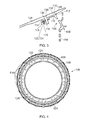
- the load spreader 122 may take the form of a carbon fibre or glass fibre disc 140, instead of the sprung steel ring 124.
- the disc 140 is relatively light weight but has significant depth, ensuring high I value and hence high stiffness to allow it to perform the load absorbing and distributing function described above.
- the two alternative forms of load spreader 122 are illustrated in Figure 7 , where the sprung steel ring 124 may be compared with the carbon or glass fibre disc 140, each being received in the plurality of recesses 120 defined at the free ends of the flexible fingers 114. It will be appreciated that all deflection and impact loads are carried by the forward (left) half of the support ring 106, allowing rigid connections to be made to the fan disc, at region 142 and to the annulus filler at region 144.
- the load spreader 122 may comprise a deep front flange 150 integrally formed with the flexible fingers 114 of the support ring 106.
- the flange 150 provides high stiffness and resistance to bending from impact loads.
- the flange 150 is split into discrete sections 152, as best illustrated in Figures 9 and 10 . The splits in the flange 150 allow each flexible finger 114 to move independently and accommodate tolerances.
- the flexible fingers 114 in the path of the deflection move radially inwards (downwards as indicated by arrow F in Figure 10 ).
- the small gap between sections 152 of the flange 150 means that only a small deflection in one section 152 can be experienced before the section 152 engages neighbouring sections 152. This effect means that the load from the impact is distributed into more flexible fingers 114 around the support ring 106, reducing the load seen by any one finger 114.
- the nose cone 104 and support ring 106 operate as a combined system to accommodate and distribute impact forces.
- a light weight yet highly impact resistant nose cone assembly 102 is provided.
- the design affords no aerodynamic penalties, such as are experienced when elliptical fixation holes are presented to the air flow in prior art designs.
- the present invention does not require the standard, heavy fixation flange that is provided on existing nose cones, and as such allows for a simpler nose cone design of reduced thickness.
- This thinner shell type structure carries a reduced risk of delamination and thermal cracking both between layers and within layers.
- the simpler structure also allows for automated lay up and manufacture of the nose cone, reducing cost compared to the hand lay up procedures currently required.
- the support ring of the present invention is also simple to manufacture from aluminum alloy. Expensive heavier metals such as are used on fully rigid support ring designs are not required.
- the design of the present invention allows aluminum to be used without exceeding the strain limit of the material, as part of a robust impact resistant design.
Landscapes
- Engineering & Computer Science (AREA)
- Chemical & Material Sciences (AREA)
- Combustion & Propulsion (AREA)
- Mechanical Engineering (AREA)
- General Engineering & Computer Science (AREA)
- Aviation & Aerospace Engineering (AREA)
- Life Sciences & Earth Sciences (AREA)
- Sustainable Development (AREA)
- Sustainable Energy (AREA)
- Structures Of Non-Positive Displacement Pumps (AREA)
- Cable Accessories (AREA)
Abstract
Description
- The present invention relates to a nose cone assembly for a gas turbine engine.
- A nose cone assembly is typically found at the intake of a gas turbine engine. The assembly conventionally comprises a one or two piece nose cone mounted on a support ring that is in turn fixed to the fan disk. The purpose of the nose cone assembly is to provide smooth inflow of air to the fan blades and to protect the rest of the engine from damage that could be caused by a foreign body impact such as a bird strike.
- A typical two piece nose cone assembly 2 is illustrated in
Figure 1 . Thenose cone 4 comprises a woven glass fibre fabric pre-impregnated with an epoxy based resin and is manufactured using a hand lay-up technique. The thickness of thenose cone 4 and the cone angle are determined by the required impact behaviour. The thickness of thenose cone 4 is determined empirically based on impact test experience and increases with radius. The angle of thenose cone 4 is determined according to both impact behaviour and the necessity to avoid ice build up on the surface of thenose cone 4. The outer surfaces 6 of thenose cone 4 are coated with polyurethane for erosion resistance on top of an epoxy based paint. A white spiral is painted onto thenose cone 4. Typically, thenose cone 4 is radially located using aspigot fit 8 onto analuminium support ring 10 and is axially located using a boltedflange 12 that mates with acorresponding flange 14 on thesupport ring 10. Thenose cone 4 is a rotationally balanced component and is circumferentially timed using dowels. Any additional component balancing is achieved using steel putty. The second piece of the nose cone assembly is thefairing 16 that maintains the annulus line between thenose cone 4 and an adjacent annulus filler (not shown). Thefairing 16 is typically made from the same composite material as thenose cone 4. Countersunk screws locate the fairing onto todiscrete brackets 18 that are attached to the main nose conesupport ring flange 14. The rear of thefairing 16 provides a support location for the leading edge of the annulus filler (not shown). Thefairing 16 is painted and coated for erosion protection in the same manner as thenose cone 4. A leading edge seal is fixed to thenose cone 4 to prevent fairing vibration. - In the event of a foreign body impact, such as a bird strike, all of the impact forces are carried by the
nose cone 4. Deflections into thesupport ring 10 could cause undesirable strains in the support ring and are thus minimised as far as possible. The connection between thenose cone 4 and thesupport ring 10 is highly rigid, ensuring any deflection caused in thenose cone 10 is limited to remain forward of the change in cone angle, illustrated at 20 inFigure 1 , and is not passed to thesupport ring 10. - In order to simplify the manufacturing process, attempts have been made to design one piece nose cone assemblies, such as for example those disclosed and illustrated in
US2008/0022524 andUS6416280 . These one piece nose cones may be attached to the support ring by angled or pocketed screws that engage the support ring flange. However, in order to ensure the necessary rigidity in the connection between nose cone and support ring, such one piece designs require comparatively thick ring sections to impart the necessary stiffness. Particularly in a large nose cone assembly, such increased thickness carries a heavy weight penalty. In addition, manufacturing issues can arise with such thick sections in a composite material, including issues with inadequate wetting, induced thermal and cure shrinkage stresses, internal cracking and delamination. However, if the thickness of the attachment sections were reduced, then high deflections would be experienced within the nose cone and passed to the support ring. Following impact with a large bird, such deflections would be sufficiently high to raise concerns over excessive strains in the support ring that could lead to failure. It is therefore desirable to provide a lightweight nose cone assembly that is nonetheless highly impact resistant. - According to the present invention, there is provided a nose cone assembly comprising a nose cone and a support ring on which the nose cone is mounted; wherein the support ring comprises a plurality of circumferentially distributed resilient attachment tabs, via which the nose cone is mounted on the support ring, the support ring further comprising a load spreader, each of the resilient attachment tabs being operably connected to the load spreader.
- The present invention thus provides a one piece nose cone assembly that can be light weight but is nonetheless highly impact resistant. This is achieved by replacing the existing nose cone and support ring arrangement with two new components designed to work together as a flexible system. Instead of carrying all impact forces through the nose cone, and imposing a heavy rigid connection between nose cone and support ring, the present invention allows deflection to be distributed throughout certain features of the support ring, sharing the loads experienced such that strains remain below the necessary levels to ensure component integrity.
- A conical surface of the nose cone may be mounted directly onto the resilient attachment tabs. In this manner the need for heavy mating flanges on the nose cone and support ring is dispensed with, simplifying construction of the nose cone in particular, and avoiding the issues specific to construction of thick composite sections.
- The resilient attachment tabs may be flexible. The attachment tabs may thus accommodate manufacturing and machining tolerances without causing damage to the nose cone itself.
- Each resilient attachment tab may comprise a nut, which may be operable to receive a bolt. The resilient attachment tabs may thus each be individually bolted to the conical surface of the nose cone. The bolts may be countersunk and may be positioned perpendicular to the annular surface in order to maintain aerodynamic efficiency.
- The resilient attachment tabs may project from a continuous annular shoulder on the support ring. The resilient attachment tabs may project in a forward direction, towards the nose of the nose cone.
- An internal conical surface of the nose cone may comprise a spigot, which may be operable to be received on the annular shoulder of the support ring.
- The shoulder may be defined between radial and axial location walls, thus providing both radial and axial location of the nose cone on the support ring.
- The load spreader of the support ring may comprise a ring and may for example comprise a sprung metallic ring. Alternatively, the load spreader may comprise a carbon fibre disc or a glass fibre disc.
- Each of the resilient attachment tabs may comprise a recess at a free end thereof, and the load spreader may be received in the plurality of recesses.
- The load spreader may be received in the recesses with some play, such that the free end of each resilient attachment tab may displace a predetermined distance before engaging on the load spreader.
- The load spreader may comprise an annular slotted flange formed on the support ring.
- The nose cone may comprise a composite material and the support ring may comprise a metallic material.
- The nose cone may comprise a filament wound glass fibre structure, a filament wound carbon fibre structure or a filament wound glass fibre and carbon fibre structure.
- According to another aspect of the present invention, there is provided a gas turbine engine having a nose cone assembly of the first aspect of the present invention.
- For a better understanding of the present invention, and to show more clearly how it may be carried into effect, reference will now be made, by way of example, to the following drawings, in which:-
-
Figure 1 is a sectional view of a nose cone assembly according to the prior art. -
Figure 2 is a sectional view of a nose cone assembly according to the present invention. -
Figure 3 is an exploded view of region A inFigure 2 . -
Figure 4 is a side view of a support ring. -
Figure 5 is a perspective view of a support ring. -
Figure 6 is a perspective view of a support ring having an alternative load spreader. -
Figure 7 is a detail view of a support ring. -
Figure 8 is a detail view of an alternative support ring. -
Figure 9 is a partial side view of another alternative support ring. -
Figure 10 is a partial view of the support ring ofFigure 9 in use. - With reference to
Figures 2 and3 , anose cone assembly 102 according to the present invention comprises a onepiece nose cone 104 and asupport ring 106. Anexemplary nose cone 104 is formed by filament winding from a 50/50 ratio by weight of S-2 Glass (RTM), e.g. 449-AA-1250, 406 Tex (g/1000m) and Carbon fibre e.g. HTA5131 6k with an epoxy resin system such as Hexcel (RTM) RTM6 resin. This system may also be used with a pre-impregnated glass fibre cone. Thesupport ring 106 may be machined from a one piece aluminium alloy (RR57) class 2 forging and sulphuric anodised all over. However, other materials such as Titanium, Carbon Fibre and stainless steels may also be used. - The
support ring 106 comprises an annularmain body 108 that is operable for substantially rigid connection to adjacent components, including for example a fan disc and an annulus filler (not shown). Themain body 108 may compriseopenings 109 at a radially inner end of themain body 108 and other attachment features as illustrated. Themain body 108 comprises a continuousannular shoulder 111 defined between aradial supporting wall 110 and an axial supportingwall 112. The continuousannular shoulder 111 is at a radially outer end of themain body 108 of thesupport ring 106. The annular shoulder is oriented so as to open towards a forward direction of thesupport ring 106, when thesupport ring 106 is oriented in its operating position within a gas turbine engine. The forward direction is from right to left in the Figures. Projecting from themain body 108, in the region of theannular shoulder 111 is a plurality of resilient attachment tabs in the form offlexible fingers 114. Theflexible fingers 114 project in a forward direction from themain body 108 of thesupport ring 106. Eachflexible finger 114 comprises anopening 116 extending through the flexible finger in a radial direction. Eachopening 116 is defined by a shank nut that is retained within theflexible finger 114. The shank nut may be sized to accept and engage with, for example, 0.7938 cm (0.3125") bolts. - The
free end 118 of eachflexible finger 114 comprises amachined recess 120. Thefree end 118 of eachflexible finger 114 is at the forward end of theflexible finger 114 and the free end 188 of eachflexible finger 114 is positioned radially inwardly of the point from which eachflexible finger 114 projects from themain body 108 of thesupport ring 106. Eachrecess 120 opens radially inwardly of its respectiveflexible finger 114. Aload spreader 122 in the form of a sprungsteel ring 124 is received within therecesses 120 formed at the ends of theflexible fingers 114. Eachrecess 120 receives thespring 124 with a small degree of play, such that a finite amount of radial inward or outward displacement may be experienced by the free end of eachflexible finger 114 before the inner walls of therecess 120 of the flexible finger engage on thespring 124. - The
nose cone 104 comprises a thin, one piece conical shell. Anannular ridge 130 defined between radial and axial locatingwalls nose cone 104. In use, theridge 130 is received in theshoulder 111 of thesupport ring 106. Respective radial and axial location walls on the ridge and shoulder engage, so as to define a dual spigot fit ensuring accurate radial and axial location of thenose cone 104 on thesupport ring 106. - A plurality of countersunk
openings 136 extend radially through thenose cone 104 to admit a plurality of fixingbolts 138. Each fixingbolt 138 passes through an associated opening in thenose cone 104 and is received within the retained shank nut on the correspondingflexible finger 114. The bolts are positioned perpendicular to the annular surface of the nose cone, thus ensuring aerodynamic efficiency. With theannular ridge 130 of thenose cone 104 received in theannular shoulder 111 of thesupport ring 106, theopenings 136 of thenose cone 104 are radially and axially aligned with therespective openings 116 on the flexible fingers. The circumferential location of thenose cone 104 on thesupport ring 106 may be timed using dowels (not shown) ensuring that thenose cone 104 may only be mounted on thesupport ring 106 in a single, balanced circumferential orientation. The play afforded by the flexibility of theflexible fingers 114 ensures that manufacturing and machining tolerances can be accommodated in ensuring secure attachment of thenose cone 104 to thesupport ring 106 without damage to thenose cone 104. - The
nose cone assembly 102 of the present invention withstands an impact event such as a bird strike by managing the deflections and impact loads generated during such an event, distributing the forces experienced by thenose cone 104 during impact. In the event of a bird impact, a large deflection is produced in thenose cone 104 at the location of the impact. In contrast to existing nose cones, in which all deflection is constrained to remain forward of the change in cone angle, thenose cone 104 of the present invention permits the "deflection pocket" caused by the impact to travel, with the bird, up thenose cone 104 until it reaches the connection with thesupport ring 106. Some of the impact forces are then transferred to the support ring via the interactingannular ridge 130 andshoulder 111. In addition, the lightweight construction of thesupport ring 106 deflects to allow the deflection pocket to pass over it. Such deflection might ordinarily be expected to cause large plastic strains in the support ring that could ultimately result in failure of the support ring. For example, if the entire deflection was carried by a singleflexible finger 114, thefinger 114 might be expected to fail. However, eachflexible finger 114 is operably connected to thesteel spring 124, and this acts as a load distributer, or load spreader. The flexible fingers in the path of the deflection pocket deflect, taking up the play in therecesses 120, until they contact thesteel spring 124. Thespring 124 both absorbs impact energy in its deflection, and distributes the impact loads among many more of the flexible fingers than were directly in the impact deflection path. The load required to deflect thesteel spring 124 is much higher than that required to deflect an individualflexible finger 114. This has the effect of reducing the load seen by theindividual fingers 114. As the finger in contact with the ring deflects further, it presses on the ring, causing the ring to deform and absorb energy. As thering 124 deforms, it presses on other flexible fingers, passing the load on to them and so distributing the load around thesupport ring 106. This action significantly reduces the load experienced by any oneflexible finger 114, ensuring that the strains experienced in thesupport ring 106 at no stage exceed the maximum allowable strains for component integrity. - In an alternative embodiment, illustrated in
Figure 6 , theload spreader 122 may take the form of a carbon fibre orglass fibre disc 140, instead of the sprungsteel ring 124. Thedisc 140 is relatively light weight but has significant depth, ensuring high I value and hence high stiffness to allow it to perform the load absorbing and distributing function described above. The two alternative forms ofload spreader 122 are illustrated inFigure 7 , where the sprungsteel ring 124 may be compared with the carbon orglass fibre disc 140, each being received in the plurality ofrecesses 120 defined at the free ends of theflexible fingers 114. It will be appreciated that all deflection and impact loads are carried by the forward (left) half of thesupport ring 106, allowing rigid connections to be made to the fan disc, atregion 142 and to the annulus filler atregion 144. - In another alternative embodiment, illustrated in
Figures 8 to 10 , theload spreader 122 may comprise a deepfront flange 150 integrally formed with theflexible fingers 114 of thesupport ring 106. Theflange 150 provides high stiffness and resistance to bending from impact loads. In order to ensure theflexible fingers 114 remain flexible, and are not so constrained by theflange 150 that they cannot deflect to accommodate tolerances in the attachment betweennose cone 104 andsupport ring 106, theflange 150 is split intodiscrete sections 152, as best illustrated inFigures 9 and 10 . The splits in theflange 150 allow eachflexible finger 114 to move independently and accommodate tolerances. When a large deflection from a bird impact is seen, theflexible fingers 114 in the path of the deflection move radially inwards (downwards as indicated by arrow F inFigure 10 ). The small gap betweensections 152 of theflange 150 means that only a small deflection in onesection 152 can be experienced before thesection 152 engages neighbouringsections 152. This effect means that the load from the impact is distributed into moreflexible fingers 114 around thesupport ring 106, reducing the load seen by any onefinger 114. - It will be appreciated that in all of the above disclosed embodiments, the
nose cone 104 andsupport ring 106 operate as a combined system to accommodate and distribute impact forces. By designing for deflection within both thenose cone 104 and thesupport ring 106, a light weight yet highly impact resistantnose cone assembly 102 is provided. The design affords no aerodynamic penalties, such as are experienced when elliptical fixation holes are presented to the air flow in prior art designs. - The present invention does not require the standard, heavy fixation flange that is provided on existing nose cones, and as such allows for a simpler nose cone design of reduced thickness. This thinner shell type structure carries a reduced risk of delamination and thermal cracking both between layers and within layers. The simpler structure also allows for automated lay up and manufacture of the nose cone, reducing cost compared to the hand lay up procedures currently required.
- The support ring of the present invention is also simple to manufacture from aluminum alloy. Expensive heavier metals such as are used on fully rigid support ring designs are not required. The design of the present invention allows aluminum to be used without exceeding the strain limit of the material, as part of a robust impact resistant design.
Claims (15)
- A nose cone assembly (102) comprising a nose cone (104) and a support ring (106), the nose cone (104) is mounted on the support ring (106); characterised in that the support ring (106) comprises a plurality of circumferentially distributed resilient attachment tabs (114), via which the nose cone (104) is mounted on the support ring (106), the support ring (106) further comprising a load spreader (122), each of the resilient attachment tabs (114) is operably connected to the load spreader (122).
- A nose cone assembly as claimed in claim 1, wherein the nose cone (104) has an internal conical surface and the internal conical surface of the nose cone (104) is mounted directly onto the resilient attachment tabs (114).
- A nose cone assembly as claimed in claim 1 or claim 2, wherein the resilient attachment tabs (114) are flexible.
- A nose cone assembly as claimed in claim 1, claim 2 or claim 3, wherein each resilient attachment tab (114) comprises a nut, operable to receive a bolt (138).
- A nose cone assembly as claimed in any one of the preceding claims, wherein the support ring (106) comprises a continuous annular shoulder (111), the resilient attachment tabs (114) project from the continuous annular shoulder (111) on the support ring (106).
- A nose cone assembly as claimed in claim 5, wherein the internal conical surface the nose cone (104) comprises a spigot, operable to be received on the annular shoulder (111) of the support ring (106).
- A nose cone assembly as claimed in claim 5 or claim 6, wherein the annular shoulder (111) is defined between radial and axial location walls (110, 112).
- A nose cone as claimed in any one of the preceding claims, wherein the load spreader (122) comprises a ring.
- A nose cone as claimed in claim 8, wherein the load spreader (122) comprises a sprung metallic ring.
- A nose cone as claimed in claim 8, wherein the load spreader (122) comprises a carbon fibre disc or a glass fibre disc.
- A nose cone assembly as claimed in any one of the preceding claims, wherein each of the resilient attachment tabs (114) comprises a recess (120) at a free end (118) thereof, and the load spreader (122) is received in the plurality of recesses (120).
- A nose cone assembly as claimed in claim 11, wherein the load spreader (122) is received in the recesses (120) with some play, such that the free end (118) of each resilient attachment tab (114) may displace a predetermined distance before engaging on the load spreader (122).
- A nose cone assembly as claimed in any one of claims 1 to 8, wherein the load spreader (122) comprises an annular slotted flange (150) formed on the support ring (106).
- A nose cone assembly as claimed in any one of the preceding claims, wherein the nose cone (104) comprises a composite material and the support ring (106) comprises a metallic material.
- A nose cone assembly as claimed in claim 14, wherein the nose cone (104) comprises a filament wound glass fibre structure, a filament wound carbon fibre structure or a filament wound glass fibre and carbon fibre structure.
Applications Claiming Priority (1)
| Application Number | Priority Date | Filing Date | Title |
|---|---|---|---|
| GBGB1020213.3A GB201020213D0 (en) | 2010-11-30 | 2010-11-30 | Nose cone assembly |
Publications (2)
| Publication Number | Publication Date |
|---|---|
| EP2458175A2 true EP2458175A2 (en) | 2012-05-30 |
| EP2458175A3 EP2458175A3 (en) | 2018-02-21 |
Family
ID=43500800
Family Applications (1)
| Application Number | Title | Priority Date | Filing Date |
|---|---|---|---|
| EP11188017.5A Withdrawn EP2458175A3 (en) | 2010-11-30 | 2011-11-07 | Nose cone assembly |
Country Status (3)
| Country | Link |
|---|---|
| US (1) | US9200595B2 (en) |
| EP (1) | EP2458175A3 (en) |
| GB (1) | GB201020213D0 (en) |
Cited By (1)
| Publication number | Priority date | Publication date | Assignee | Title |
|---|---|---|---|---|
| GB2503075A (en) * | 2012-04-05 | 2013-12-18 | Snecma | System for attaching a turbojet engine spinner |
Families Citing this family (11)
| Publication number | Priority date | Publication date | Assignee | Title |
|---|---|---|---|---|
| US9759129B2 (en) * | 2012-12-28 | 2017-09-12 | United Technologies Corporation | Removable nosecone for a gas turbine engine |
| US9682450B2 (en) * | 2013-01-11 | 2017-06-20 | United Technologies Corporation | Gas turbine engine nose cone attachment configuration |
| US10100644B2 (en) | 2014-03-03 | 2018-10-16 | Rolls-Royce Corporation | Spinner for a gas turbine engine |
| US10099772B2 (en) * | 2014-10-31 | 2018-10-16 | Hamilton Sundstrand Corporation | Ice-shedding spinner for ram air turbine |
| KR101821503B1 (en) * | 2016-11-04 | 2018-01-23 | 두산중공업 주식회사 | Flow guide structure for turbine's inner casing flange |
| US10746031B2 (en) | 2017-07-18 | 2020-08-18 | Rolls-Royce Corporation | Annulus filler |
| US11078839B2 (en) | 2018-01-22 | 2021-08-03 | Rolls-Royce Corporation | Composite nosecone |
| GB201816894D0 (en) * | 2018-10-17 | 2018-11-28 | Rolls Royce Plc | Component shielding |
| US11421538B2 (en) | 2020-05-12 | 2022-08-23 | Rolls-Royce Corporation | Composite aerofoils |
| US11506083B2 (en) | 2020-06-03 | 2022-11-22 | Rolls-Royce Corporalion | Composite liners for turbofan engines |
| KR102774545B1 (en) * | 2023-12-14 | 2025-02-27 | 백선준 | Blocking structure that prevents bird from entering aircraft engines |
Citations (2)
| Publication number | Priority date | Publication date | Assignee | Title |
|---|---|---|---|---|
| US6416280B1 (en) | 2000-11-27 | 2002-07-09 | General Electric Company | One piece spinner |
| US20080022524A1 (en) | 2006-03-10 | 2008-01-31 | Karl Schreiber | Intake cone in a fiber compound material for a gas turbine engine and method for its manufacture |
Family Cites Families (14)
| Publication number | Priority date | Publication date | Assignee | Title |
|---|---|---|---|---|
| US3990814A (en) * | 1975-06-25 | 1976-11-09 | United Technologies Corporation | Spinner |
| US4598544A (en) * | 1983-04-28 | 1986-07-08 | Williams International Corporation | Medium bypass turbofan engine |
| FR2621554B1 (en) * | 1987-10-07 | 1990-01-05 | Snecma | NON-ROTATING INPUT COVER OF CENTRALLY FIXED TURBOREACTOR AND TURBOREACTOR THUS EQUIPPED |
| US5833435A (en) * | 1996-12-24 | 1998-11-10 | United Technologies Corporation | Inlet nose cone assembly and method for repairing the assembly |
| GB9828812D0 (en) * | 1998-12-29 | 1999-02-17 | Rolls Royce Plc | Gas turbine nose cone assembly |
| GB2363170A (en) * | 2000-06-08 | 2001-12-12 | Rolls Royce Plc | Attaching a nose cone to a gas turbine engine rotor |
| GB2364748A (en) | 2000-07-15 | 2002-02-06 | Rolls Royce Plc | Gas turbine engine nose cone with tool access hole plug/cover |
| GB0102169D0 (en) * | 2001-01-27 | 2001-03-14 | Rolls Royce Plc | A gas turbine engine nose cone |
| GB2398353B (en) * | 2003-02-14 | 2006-02-15 | Rolls Royce Plc | A gas turbine engine nose cone |
| GB0803366D0 (en) | 2008-02-26 | 2008-04-02 | Rolls Royce Plc | Nose cone assembly |
| FR2930595B1 (en) * | 2008-04-24 | 2011-10-14 | Snecma | BLOWER ROTOR OF A TURBOMACHINE OR A TEST ENGINE |
| DE102008045546A1 (en) | 2008-09-03 | 2010-03-04 | Rolls-Royce Deutschland Ltd & Co Kg | Aircraft gas turbine inlet cone |
| GB0903012D0 (en) * | 2009-02-24 | 2009-04-08 | Rolls Royce Plc | Mounting arrangement |
| DE102009016802A1 (en) * | 2009-04-09 | 2010-10-14 | Rolls-Royce Deutschland Ltd & Co Kg | Fiber composite inlet cone for a gas turbine engine |
-
2010
- 2010-11-30 GB GBGB1020213.3A patent/GB201020213D0/en not_active Ceased
-
2011
- 2011-11-07 EP EP11188017.5A patent/EP2458175A3/en not_active Withdrawn
- 2011-11-07 US US13/290,563 patent/US9200595B2/en not_active Expired - Fee Related
Patent Citations (2)
| Publication number | Priority date | Publication date | Assignee | Title |
|---|---|---|---|---|
| US6416280B1 (en) | 2000-11-27 | 2002-07-09 | General Electric Company | One piece spinner |
| US20080022524A1 (en) | 2006-03-10 | 2008-01-31 | Karl Schreiber | Intake cone in a fiber compound material for a gas turbine engine and method for its manufacture |
Cited By (2)
| Publication number | Priority date | Publication date | Assignee | Title |
|---|---|---|---|---|
| GB2503075A (en) * | 2012-04-05 | 2013-12-18 | Snecma | System for attaching a turbojet engine spinner |
| GB2503075B (en) * | 2012-04-05 | 2018-06-06 | Snecma | System for attaching a turbojet engine spinner |
Also Published As
| Publication number | Publication date |
|---|---|
| EP2458175A3 (en) | 2018-02-21 |
| GB201020213D0 (en) | 2011-01-12 |
| US20120134844A1 (en) | 2012-05-31 |
| US9200595B2 (en) | 2015-12-01 |
Similar Documents
| Publication | Publication Date | Title |
|---|---|---|
| US9200595B2 (en) | Nose cone assembly | |
| US10669934B2 (en) | Nose cone assembly | |
| CN115989369B (en) | Aircraft turbine engine comprising variable pitch propeller blades | |
| EP2388441B1 (en) | Fan case with rub elements | |
| EP1857639B1 (en) | Fan frame | |
| US8672609B2 (en) | Composite fan containment case assembly | |
| US10723445B2 (en) | Strake for aircraft propulsion system nacelle | |
| CN104105868B (en) | Composite fan containment case assembly | |
| EP2837772B1 (en) | Annulus filler and corresponding stage and gas turbine engine | |
| US9963986B2 (en) | Coupling part structure for vane and jet engine including the same | |
| EP2041399A2 (en) | Aircraft engine inlet having zone of deformation | |
| EP2495402B1 (en) | Fan casing for a turbofan engine | |
| US9102413B2 (en) | Fastening device particularly suitable for the fastening between an air intake and an engine of an aircraft nacelle | |
| US10385703B2 (en) | Fan blades with protective sheaths and galvanic shields | |
| EP2865879B1 (en) | Vane linking portion structure, and jet engine using same | |
| RU2614303C2 (en) | Housing with edges for axial turbine machine compressor | |
| US10767486B2 (en) | Mistuned concentric airfoil assembly and method of mistuning same | |
| CN117940339A (en) | Propeller for an aircraft turbomachine |
Legal Events
| Date | Code | Title | Description |
|---|---|---|---|
| PUAI | Public reference made under article 153(3) epc to a published international application that has entered the european phase |
Free format text: ORIGINAL CODE: 0009012 |
|
| AK | Designated contracting states |
Kind code of ref document: A2 Designated state(s): AL AT BE BG CH CY CZ DE DK EE ES FI FR GB GR HR HU IE IS IT LI LT LU LV MC MK MT NL NO PL PT RO RS SE SI SK SM TR |
|
| AX | Request for extension of the european patent |
Extension state: BA ME |
|
| RAP1 | Party data changed (applicant data changed or rights of an application transferred) |
Owner name: ROLLS-ROYCE PLC |
|
| PUAL | Search report despatched |
Free format text: ORIGINAL CODE: 0009013 |
|
| AK | Designated contracting states |
Kind code of ref document: A3 Designated state(s): AL AT BE BG CH CY CZ DE DK EE ES FI FR GB GR HR HU IE IS IT LI LT LU LV MC MK MT NL NO PL PT RO RS SE SI SK SM TR |
|
| AX | Request for extension of the european patent |
Extension state: BA ME |
|
| RIC1 | Information provided on ipc code assigned before grant |
Ipc: F02C 7/04 20060101AFI20180116BHEP |
|
| STAA | Information on the status of an ep patent application or granted ep patent |
Free format text: STATUS: THE APPLICATION HAS BEEN PUBLISHED |
|
| STAA | Information on the status of an ep patent application or granted ep patent |
Free format text: STATUS: THE APPLICATION IS DEEMED TO BE WITHDRAWN |
|
| 18D | Application deemed to be withdrawn |
Effective date: 20180822 |