EP2458171A2 - Contamination sensor - Google Patents
Contamination sensor Download PDFInfo
- Publication number
- EP2458171A2 EP2458171A2 EP11189678A EP11189678A EP2458171A2 EP 2458171 A2 EP2458171 A2 EP 2458171A2 EP 11189678 A EP11189678 A EP 11189678A EP 11189678 A EP11189678 A EP 11189678A EP 2458171 A2 EP2458171 A2 EP 2458171A2
- Authority
- EP
- European Patent Office
- Prior art keywords
- rubber
- sensor
- tank
- contact
- urea
- Prior art date
- Legal status (The legal status is an assumption and is not a legal conclusion. Google has not performed a legal analysis and makes no representation as to the accuracy of the status listed.)
- Withdrawn
Links
Images




Classifications
-
- F—MECHANICAL ENGINEERING; LIGHTING; HEATING; WEAPONS; BLASTING
- F01—MACHINES OR ENGINES IN GENERAL; ENGINE PLANTS IN GENERAL; STEAM ENGINES
- F01N—GAS-FLOW SILENCERS OR EXHAUST APPARATUS FOR MACHINES OR ENGINES IN GENERAL; GAS-FLOW SILENCERS OR EXHAUST APPARATUS FOR INTERNAL-COMBUSTION ENGINES
- F01N3/00—Exhaust or silencing apparatus having means for purifying, rendering innocuous, or otherwise treating exhaust
- F01N3/08—Exhaust or silencing apparatus having means for purifying, rendering innocuous, or otherwise treating exhaust for rendering innocuous
- F01N3/10—Exhaust or silencing apparatus having means for purifying, rendering innocuous, or otherwise treating exhaust for rendering innocuous by thermal or catalytic conversion of noxious components of exhaust
- F01N3/18—Exhaust or silencing apparatus having means for purifying, rendering innocuous, or otherwise treating exhaust for rendering innocuous by thermal or catalytic conversion of noxious components of exhaust characterised by methods of operation; Control
- F01N3/20—Exhaust or silencing apparatus having means for purifying, rendering innocuous, or otherwise treating exhaust for rendering innocuous by thermal or catalytic conversion of noxious components of exhaust characterised by methods of operation; Control specially adapted for catalytic conversion
- F01N3/206—Adding periodically or continuously substances to exhaust gases for promoting purification, e.g. catalytic material in liquid form, NOx reducing agents
- F01N3/2066—Selective catalytic reduction [SCR]
-
- F—MECHANICAL ENGINEERING; LIGHTING; HEATING; WEAPONS; BLASTING
- F01—MACHINES OR ENGINES IN GENERAL; ENGINE PLANTS IN GENERAL; STEAM ENGINES
- F01N—GAS-FLOW SILENCERS OR EXHAUST APPARATUS FOR MACHINES OR ENGINES IN GENERAL; GAS-FLOW SILENCERS OR EXHAUST APPARATUS FOR INTERNAL-COMBUSTION ENGINES
- F01N11/00—Monitoring or diagnostic devices for exhaust-gas treatment apparatus
-
- G—PHYSICS
- G01—MEASURING; TESTING
- G01M—TESTING STATIC OR DYNAMIC BALANCE OF MACHINES OR STRUCTURES; TESTING OF STRUCTURES OR APPARATUS, NOT OTHERWISE PROVIDED FOR
- G01M3/00—Investigating fluid-tightness of structures
- G01M3/02—Investigating fluid-tightness of structures by using fluid or vacuum
- G01M3/025—Details with respect to the testing of engines or engine parts
-
- G—PHYSICS
- G01—MEASURING; TESTING
- G01M—TESTING STATIC OR DYNAMIC BALANCE OF MACHINES OR STRUCTURES; TESTING OF STRUCTURES OR APPARATUS, NOT OTHERWISE PROVIDED FOR
- G01M3/00—Investigating fluid-tightness of structures
- G01M3/02—Investigating fluid-tightness of structures by using fluid or vacuum
- G01M3/04—Investigating fluid-tightness of structures by using fluid or vacuum by detecting the presence of fluid at the leakage point
- G01M3/042—Investigating fluid-tightness of structures by using fluid or vacuum by detecting the presence of fluid at the leakage point by using materials which expand, contract, disintegrate, or decompose in contact with a fluid
-
- G—PHYSICS
- G01—MEASURING; TESTING
- G01M—TESTING STATIC OR DYNAMIC BALANCE OF MACHINES OR STRUCTURES; TESTING OF STRUCTURES OR APPARATUS, NOT OTHERWISE PROVIDED FOR
- G01M3/00—Investigating fluid-tightness of structures
- G01M3/02—Investigating fluid-tightness of structures by using fluid or vacuum
- G01M3/04—Investigating fluid-tightness of structures by using fluid or vacuum by detecting the presence of fluid at the leakage point
- G01M3/042—Investigating fluid-tightness of structures by using fluid or vacuum by detecting the presence of fluid at the leakage point by using materials which expand, contract, disintegrate, or decompose in contact with a fluid
- G01M3/045—Investigating fluid-tightness of structures by using fluid or vacuum by detecting the presence of fluid at the leakage point by using materials which expand, contract, disintegrate, or decompose in contact with a fluid with electrical detection means
-
- F—MECHANICAL ENGINEERING; LIGHTING; HEATING; WEAPONS; BLASTING
- F01—MACHINES OR ENGINES IN GENERAL; ENGINE PLANTS IN GENERAL; STEAM ENGINES
- F01N—GAS-FLOW SILENCERS OR EXHAUST APPARATUS FOR MACHINES OR ENGINES IN GENERAL; GAS-FLOW SILENCERS OR EXHAUST APPARATUS FOR INTERNAL-COMBUSTION ENGINES
- F01N2550/00—Monitoring or diagnosing the deterioration of exhaust systems
- F01N2550/05—Systems for adding substances into exhaust
-
- F—MECHANICAL ENGINEERING; LIGHTING; HEATING; WEAPONS; BLASTING
- F01—MACHINES OR ENGINES IN GENERAL; ENGINE PLANTS IN GENERAL; STEAM ENGINES
- F01N—GAS-FLOW SILENCERS OR EXHAUST APPARATUS FOR MACHINES OR ENGINES IN GENERAL; GAS-FLOW SILENCERS OR EXHAUST APPARATUS FOR INTERNAL-COMBUSTION ENGINES
- F01N2610/00—Adding substances to exhaust gases
- F01N2610/02—Adding substances to exhaust gases the substance being ammonia or urea
-
- F—MECHANICAL ENGINEERING; LIGHTING; HEATING; WEAPONS; BLASTING
- F01—MACHINES OR ENGINES IN GENERAL; ENGINE PLANTS IN GENERAL; STEAM ENGINES
- F01N—GAS-FLOW SILENCERS OR EXHAUST APPARATUS FOR MACHINES OR ENGINES IN GENERAL; GAS-FLOW SILENCERS OR EXHAUST APPARATUS FOR INTERNAL-COMBUSTION ENGINES
- F01N2610/00—Adding substances to exhaust gases
- F01N2610/14—Arrangements for the supply of substances, e.g. conduits
- F01N2610/1406—Storage means for substances, e.g. tanks or reservoirs
-
- F—MECHANICAL ENGINEERING; LIGHTING; HEATING; WEAPONS; BLASTING
- F01—MACHINES OR ENGINES IN GENERAL; ENGINE PLANTS IN GENERAL; STEAM ENGINES
- F01N—GAS-FLOW SILENCERS OR EXHAUST APPARATUS FOR MACHINES OR ENGINES IN GENERAL; GAS-FLOW SILENCERS OR EXHAUST APPARATUS FOR INTERNAL-COMBUSTION ENGINES
- F01N2610/00—Adding substances to exhaust gases
- F01N2610/14—Arrangements for the supply of substances, e.g. conduits
- F01N2610/148—Arrangement of sensors
-
- F—MECHANICAL ENGINEERING; LIGHTING; HEATING; WEAPONS; BLASTING
- F01—MACHINES OR ENGINES IN GENERAL; ENGINE PLANTS IN GENERAL; STEAM ENGINES
- F01N—GAS-FLOW SILENCERS OR EXHAUST APPARATUS FOR MACHINES OR ENGINES IN GENERAL; GAS-FLOW SILENCERS OR EXHAUST APPARATUS FOR INTERNAL-COMBUSTION ENGINES
- F01N2900/00—Details of electrical control or of the monitoring of the exhaust gas treating apparatus
- F01N2900/06—Parameters used for exhaust control or diagnosing
- F01N2900/18—Parameters used for exhaust control or diagnosing said parameters being related to the system for adding a substance into the exhaust
- F01N2900/1806—Properties of reducing agent or dosing system
-
- G—PHYSICS
- G01—MEASURING; TESTING
- G01N—INVESTIGATING OR ANALYSING MATERIALS BY DETERMINING THEIR CHEMICAL OR PHYSICAL PROPERTIES
- G01N27/00—Investigating or analysing materials by the use of electric, electrochemical, or magnetic means
- G01N27/02—Investigating or analysing materials by the use of electric, electrochemical, or magnetic means by investigating impedance
- G01N27/04—Investigating or analysing materials by the use of electric, electrochemical, or magnetic means by investigating impedance by investigating resistance
- G01N27/12—Investigating or analysing materials by the use of electric, electrochemical, or magnetic means by investigating impedance by investigating resistance of a solid body in dependence upon absorption of a fluid; of a solid body in dependence upon reaction with a fluid, for detecting components in the fluid
- G01N27/125—Composition of the body, e.g. the composition of its sensitive layer
- G01N27/126—Composition of the body, e.g. the composition of its sensitive layer comprising organic polymers
-
- H—ELECTRICITY
- H01—ELECTRIC ELEMENTS
- H01H—ELECTRIC SWITCHES; RELAYS; SELECTORS; EMERGENCY PROTECTIVE DEVICES
- H01H35/00—Switches operated by change of a physical condition
- H01H35/24—Switches operated by change of fluid pressure, by fluid pressure waves, or by change of fluid flow
-
- Y—GENERAL TAGGING OF NEW TECHNOLOGICAL DEVELOPMENTS; GENERAL TAGGING OF CROSS-SECTIONAL TECHNOLOGIES SPANNING OVER SEVERAL SECTIONS OF THE IPC; TECHNICAL SUBJECTS COVERED BY FORMER USPC CROSS-REFERENCE ART COLLECTIONS [XRACs] AND DIGESTS
- Y02—TECHNOLOGIES OR APPLICATIONS FOR MITIGATION OR ADAPTATION AGAINST CLIMATE CHANGE
- Y02T—CLIMATE CHANGE MITIGATION TECHNOLOGIES RELATED TO TRANSPORTATION
- Y02T10/00—Road transport of goods or passengers
- Y02T10/10—Internal combustion engine [ICE] based vehicles
- Y02T10/12—Improving ICE efficiencies
-
- Y—GENERAL TAGGING OF NEW TECHNOLOGICAL DEVELOPMENTS; GENERAL TAGGING OF CROSS-SECTIONAL TECHNOLOGIES SPANNING OVER SEVERAL SECTIONS OF THE IPC; TECHNICAL SUBJECTS COVERED BY FORMER USPC CROSS-REFERENCE ART COLLECTIONS [XRACs] AND DIGESTS
- Y02—TECHNOLOGIES OR APPLICATIONS FOR MITIGATION OR ADAPTATION AGAINST CLIMATE CHANGE
- Y02T—CLIMATE CHANGE MITIGATION TECHNOLOGIES RELATED TO TRANSPORTATION
- Y02T10/00—Road transport of goods or passengers
- Y02T10/10—Internal combustion engine [ICE] based vehicles
- Y02T10/40—Engine management systems
Definitions
- This invention relates to detection of contamination in urea solution tanks in SCR systems and more specifically to a sensor for this purpose.
- An NO x selective reduction catalyst is used in certain cases in exhaust cleaning to reduce nitrogen oxides (NO x ) such as are for example released from diesel-powered vehicles, using an aqueous solution of urea as reducing agent. It is known that such a solution with a urea content of 32.5 wt% is with advantage usable to effectively achieve this reducing reaction. It sometimes happens, however, that the urea concentration in the tank containing the solution varies over time. There is also risk that the tank might be contaminated by other solutions or liquids, e.g. oil, which by mistake or accidentally make their way into the tank. It has therefore been proposed to use urea sensors to monitor the urea concentration in the solution in the tank. A version is described in US2007/00544091 A1 .
- a urea sensor has a detection portion which is used by being immersed in a liquid contained in a urea tank to detect the thermal conductivity of the liquid and thereby determine whether the solution in the tank is an aqueous solution of urea.
- a casing which surrounds a periphery of the detection portion and is penetrated by one or more holes.
- a lower hole is of such configuration and size as to readily accommodate a first hypothetical circle with a diameter of not less than 3.5 mm. At least part of the lower hole is situated below the detection portion when the urea sensor is installed in the urea solution tank.
- That specification therefore describes a urea sensor which monitors the concentration of urea and conveys alarm if the concentration deviates from a setpoint value.
- the object is thus to propose an effective and inexpensive sensor for determining whether the urea solution is contaminated by, for example, diesel fuel, which sensor immediately conveys alarm when such is the case.
- a sensor is adapted to detecting any presence of petroleum products, e.g. diesel fuel, in a urea solution intended for use in an exhaust cleaning system based on catalysis.
- the sensor is preferably made of rubber material which has the characteristic of expanding upon contact with petroleum products, e.g. diesel fuel.
- This expansion is preferably used to exert a mechanical effect upon a contact or some other means so that an electrical circuit is closed or broken.
- the fundamental inventive concept of the present invention is detecting whether petroleum products have contaminated the urea solution in a tank belonging to an SCR system for catalytic exhaust cleaning.
- the invention is based on using a sensor which monitors for presence of small amounts of petroleum products, e.g. diesel fuel.
- the senor comprises rubber material which has the property of expanding when in contact with petroleum products. This expansion is used in different variants in different ways to generate a signal.
- a sensor in the form of a composite element 12 in which a rubber block 13 or the like has at least one planar surface on which a flexible metal plate (sheet or foil) 14 is bonded.
- Fig. 1a depicts such a sensor element.
- the metal portion has two functions, one being to serve as a diffusion barrier (to prevent organic substances from making their way in), the other to be electrically conductive. This may be achieved in two ways, either by means of metal foil which both serves as barrier layer and can close an electrical circuit, or by putting in place a barrier layer, e.g. of polytetrafluoroethylene (Teflon®) and placing on it a metal foil (not necessarily covering the whole rubber surface) which is capable of closing a circuit.
- a barrier layer e.g. of polytetrafluoroethylene (Teflon®) and placing on it a metal foil (not necessarily covering the whole rubber surface) which is capable of closing a circuit.
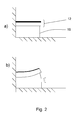
- the metal plate 14 which is not affected by petroleum products, will prevent the rubber 13 from expanding on the side adjacent to it, whereas the rubber will expand on the opposite side, leading to bending of the whole composite element as depicted in Fig. 1b (comparable with how a bimetal reacts when warmed).
- Expansion of rubber is typically 100%, resulting in a substantial deflection of the sensor element when exposed to oil.
- the spacing has to be enough to avoid accidental contact, e.g. due to vibration.
- the composite element 12 is with advantage firmly clamped at one end but unattached at the other end (see Figs. 1a-b ). If a contact element 16 made of metal is situated adjacent to the metal plate 14 of the composite element 12, these two metal elements may be brought into contact by the bending due to the expansion of the rubber, thereby closing an electrical circuit and consequently generating an electrical signal which can be used to give warning that contamination has occurred.
- the rubber element 13 may be used as a one-way sensor, in which case a thin electrically conductive wire 18 is connected, as depicted in Fig. 2a , to the unattached end of the composite element 12 which is configured in the same way as described with reference to Fig. 1 .
- a thin electrically conductive wire 18 is connected, as depicted in Fig. 2a , to the unattached end of the composite element 12 which is configured in the same way as described with reference to Fig. 1 .
- the rubber expands through having come into contact with, for example, diesel oil, it bends and the wire 18 is stretched far enough to break, see Fig. 2b . If a current is passing through the wire, the circuit is therefore broken when the wire breaks, generating a signal which can be used to give warning that contamination has occurred.
- Fig. 3 depicts another embodiment of the invention.
- the senor takes the form of a rubber strand 20, i.e. a relatively thin and elongate rubber element. Suitable dimensions are 2-10 cm long and a cross-section of up to 1x5 mm, i.e. the strand is preferably in strip form. A rectangular cross-section is best because a large surface is preferred.
- the rubber strand is preferably fixed at one end 22. If the sensor is situated in a tank, it is preferably fastened to the bottom or a wall of the tank. At the other end of the rubber strand 22 there is a metal element 24 which has the function of closing an electrical circuit, as explained in the description below.
- a spring 26 preferably a coil spring. This spring keeps the rubber strand 20 in a stretched state and keeps it straight even when it expands upon contact with, for example, oil or diesel fuel.
- the rubber strand 20 is so arranged that its metal element 24 is adjacent to a contact element which comprises two electrically conductive parts 28a, 28b at a distance from one another. A voltage is constantly applied across these contact elements.
- the spring 26 runs through the intermediate space 29 between the contact elements 28a, 28b.
- the metal element 24, e.g. in the form of a washer or ball situated on the rubber strand 22, is somewhat larger than the distance between the contact elements 28a, 28b, with the result that when the rubber expands the spring 26 will pull the strand 22, and consequently also the metal element 24 situated on the strand, towards the contact elements 28a, 28b, and when the rubber has expanded enough, i.e. when the strand has lengthened, the metal element 24 will come into contact with the two contact elements 28a, 28b and an electrical circuit will close, generating a signal which can be used to give warning that contamination has occurred.
- the senor 40 comprises a container 42 which is situated in the tank or the fuel pipe and which has at least one aperture, preferably a set of apertures 44, through which the liquid contained in or being put into the tank can enter.
- This container contains a set of rubber elements, preferably in the form of balls 46 with a diameter of between 1 and 3 mm.
- contact means 48, 49 in the form of a flexible tongue 48 which is situated with a gap G between it and a contact surface 49 and which is acted upon by the rubber elements when they expand, so that an electrical circuit is closed or broken, generating a signal.
- the container may be made of perforated material with a plurality of apertures, the size of which apertures may vary within wide limits. The limitation is imposed by the size of the balls. The holes should be understood at being not larger than the balls.
- a preferred ball size is 1-3 mm diameter, and a mesh size of a grid is preferably 0.5-1.5 mm.
- the container is made of a gridlike material, which may be polymer or metal, but in the latter case preferably electrically isolated on the surface.
- a contact element so situated as to be mechanically acted upon by the expanding rubber balls so that an electrical circuit is closed and a signal is generated.
- the contact element takes the form of a resilient metal tongue 48 adjacent to the bottom or a wall of the container.
- a resilient metal tongue 48 adjacent to the bottom or a wall of the container.
- a thin metal foil is so situated that it is broken when the balls expand. If the metal foil is so configured that in an unbroken state it conducts current but in a broken state it prevents current from flowing, i.e. an electrical circuit is broken, this may also be utilised to generate a signal in a similar way to the "wire variant" in Fig. 1b .
- a thin metal wire (not depicted) is provided in a similar way to Fig. 2b , it may be caused to break and an electrical circuit to be broken, which may generate a signal.
- a sensor unit 50 may be provided in a tank 51 for urea solution 52 as depicted in Fig. 5a , in which case the sensor unit is preferably fitted on a wall close to the inlet from the tank pipe 53 so that any contaminating liquid comes immediately into contact with the sensor 50 and quickly generates a warning signal.
- the sensor unit may be fitted in the tank pipe 53 as in Fig. 5b , in which case it is conceivable for the tank pipe to be provided with a separate pipe 54 or pipe segment in which the sensor 50 is fitted.
- the senor In both of these embodiments, it is in principle only when the tank is being filled that the sensor will thus be in contact with liquid.
- the sensor might also be so arranged that it is continually immersed in the fuel and monitors continuously the composition of the liquid.
- the rubber element may be connected to an electrical resistance meter adapted to measuring a change in the resistance of the rubber when it expands in contact with petroleum products
Landscapes
- Engineering & Computer Science (AREA)
- Chemical & Material Sciences (AREA)
- Chemical Kinetics & Catalysis (AREA)
- Mechanical Engineering (AREA)
- General Engineering & Computer Science (AREA)
- Combustion & Propulsion (AREA)
- General Physics & Mathematics (AREA)
- Physics & Mathematics (AREA)
- Toxicology (AREA)
- Health & Medical Sciences (AREA)
- Measurement Of Levels Of Liquids Or Fluent Solid Materials (AREA)
- Investigating Or Analyzing Materials By The Use Of Electric Means (AREA)
- Exhaust Gas After Treatment (AREA)
Abstract
Description
- This invention relates to detection of contamination in urea solution tanks in SCR systems and more specifically to a sensor for this purpose.
- An NOx selective reduction catalyst (SCR) is used in certain cases in exhaust cleaning to reduce nitrogen oxides (NOx) such as are for example released from diesel-powered vehicles, using an aqueous solution of urea as reducing agent. It is known that such a solution with a urea content of 32.5 wt% is with advantage usable to effectively achieve this reducing reaction. It sometimes happens, however, that the urea concentration in the tank containing the solution varies over time. There is also risk that the tank might be contaminated by other solutions or liquids, e.g. oil, which by mistake or accidentally make their way into the tank. It has therefore been proposed to use urea sensors to monitor the urea concentration in the solution in the tank. A version is described in
US2007/00544091 A1 - A further development of this technique is described in
US2008/205478 A1 , in which a urea sensor has a detection portion which is used by being immersed in a liquid contained in a urea tank to detect the thermal conductivity of the liquid and thereby determine whether the solution in the tank is an aqueous solution of urea. There is also a casing which surrounds a periphery of the detection portion and is penetrated by one or more holes. A lower hole is of such configuration and size as to readily accommodate a first hypothetical circle with a diameter of not less than 3.5 mm. At least part of the lower hole is situated below the detection portion when the urea sensor is installed in the urea solution tank. - That specification therefore describes a urea sensor which monitors the concentration of urea and conveys alarm if the concentration deviates from a setpoint value.
- None of these prior art devices describe direct and continuous monitoring for presence of contaminating substances in the urea solution.
- In the light of the problems pertaining to the technique described in the introduction, the inventors have devised a novel detection method and sensors for detection of organic contaminants, especially petroleum products (e.g. diesel fuel and solvents) in the urea tank of an SCR system.
- The object is thus to propose an effective and inexpensive sensor for determining whether the urea solution is contaminated by, for example, diesel fuel, which sensor immediately conveys alarm when such is the case.
- This object is achieved with a device according to claim 1 whereby a sensor is adapted to detecting any presence of petroleum products, e.g. diesel fuel, in a urea solution intended for use in an exhaust cleaning system based on catalysis.
- The sensor is preferably made of rubber material which has the characteristic of expanding upon contact with petroleum products, e.g. diesel fuel.
- This expansion is preferably used to exert a mechanical effect upon a contact or some other means so that an electrical circuit is closed or broken.
- The invention is explained below in more detail with reference to the attached drawings, in which
-
Fig. 1a depicts an embodiment of a sensor according to the invention in an unexpanded state, -
Fig. 1b depicts the sensor inFig. 1a in an expanded state whereby a contact is closed, -
Fig. 2a depicts another embodiment of a sensor according to the invention in an unexpanded state, -
Fig. 2b depicts the sensor inFig. 2a in an expanded state whereby a wire is broken and an electrical circuit is consequently broken, -
Fig. 3 depicts a further embodiment of a sensor according to the invention, -
Fig. 4a depicts yet another embodiment of a sensor according to the invention, -
Fig. 4b depicts a variant of the embodiment inFig. 4a , -
Fig. 5a depicts a location of a sensor, and -
Fig. 5b depicts another location of a sensor. - The fundamental inventive concept of the present invention is detecting whether petroleum products have contaminated the urea solution in a tank belonging to an SCR system for catalytic exhaust cleaning.
- The invention is based on using a sensor which monitors for presence of small amounts of petroleum products, e.g. diesel fuel.
- In a preferred embodiment, the sensor comprises rubber material which has the property of expanding when in contact with petroleum products. This expansion is used in different variants in different ways to generate a signal.
- In an embodiment, a sensor, generally designated by ref. 10, is provided in the form of a
composite element 12 in which arubber block 13 or the like has at least one planar surface on which a flexible metal plate (sheet or foil) 14 is bonded.Fig. 1a depicts such a sensor element. - The metal portion has two functions, one being to serve as a diffusion barrier (to prevent organic substances from making their way in), the other to be electrically conductive. This may be achieved in two ways, either by means of metal foil which both serves as barrier layer and can close an electrical circuit, or by putting in place a barrier layer, e.g. of polytetrafluoroethylene (Teflon®) and placing on it a metal foil (not necessarily covering the whole rubber surface) which is capable of closing a circuit.
- When the rubber/metal
composite element 12 comes into contact with a petroleum product which causes the rubber to expand, themetal plate 14, which is not affected by petroleum products, will prevent therubber 13 from expanding on the side adjacent to it, whereas the rubber will expand on the opposite side, leading to bending of the whole composite element as depicted inFig. 1b (comparable with how a bimetal reacts when warmed). - Expansion of rubber is typically 100%, resulting in a substantial deflection of the sensor element when exposed to oil. The spacing has to be enough to avoid accidental contact, e.g. due to vibration.
- The
composite element 12 is with advantage firmly clamped at one end but unattached at the other end (seeFigs. 1a-b ). If acontact element 16 made of metal is situated adjacent to themetal plate 14 of thecomposite element 12, these two metal elements may be brought into contact by the bending due to the expansion of the rubber, thereby closing an electrical circuit and consequently generating an electrical signal which can be used to give warning that contamination has occurred. - In an alternative embodiment, the
rubber element 13 may be used as a one-way sensor, in which case a thin electricallyconductive wire 18 is connected, as depicted inFig. 2a , to the unattached end of thecomposite element 12 which is configured in the same way as described with reference toFig. 1 . When the rubber expands through having come into contact with, for example, diesel oil, it bends and thewire 18 is stretched far enough to break, seeFig. 2b . If a current is passing through the wire, the circuit is therefore broken when the wire breaks, generating a signal which can be used to give warning that contamination has occurred. -
Fig. 3 depicts another embodiment of the invention. - In this case the sensor takes the form of a
rubber strand 20, i.e. a relatively thin and elongate rubber element. Suitable dimensions are 2-10 cm long and a cross-section of up to 1x5 mm, i.e. the strand is preferably in strip form. A rectangular cross-section is best because a large surface is preferred. - The rubber strand is preferably fixed at one
end 22. If the sensor is situated in a tank, it is preferably fastened to the bottom or a wall of the tank. At the other end of therubber strand 22 there is ametal element 24 which has the function of closing an electrical circuit, as explained in the description below. - At the same end as the metal element there is a
spring 26, preferably a coil spring. This spring keeps therubber strand 20 in a stretched state and keeps it straight even when it expands upon contact with, for example, oil or diesel fuel. - The
rubber strand 20 is so arranged that itsmetal element 24 is adjacent to a contact element which comprises two electricallyconductive parts spring 26 runs through theintermediate space 29 between thecontact elements metal element 24, e.g. in the form of a washer or ball situated on therubber strand 22, is somewhat larger than the distance between thecontact elements spring 26 will pull thestrand 22, and consequently also themetal element 24 situated on the strand, towards thecontact elements metal element 24 will come into contact with the twocontact elements - It is possible to arrange the
rubber strand 20 and themetal element 24 in such a way that the strand runs through thepassage 29, in which case themetal element 24 will therefore not be on the end of thestrand 20 but somewhere along it. It is important that thespring 26 keeps the strand straight when it expands and that the distance between themetal element 24 and thecontact elements - In a further alternative embodiment illustrated in
Figs. 4a-b , thesensor 40 comprises acontainer 42 which is situated in the tank or the fuel pipe and which has at least one aperture, preferably a set ofapertures 44, through which the liquid contained in or being put into the tank can enter. This container contains a set of rubber elements, preferably in the form ofballs 46 with a diameter of between 1 and 3 mm. There is also a contact means 48, 49 in the form of aflexible tongue 48 which is situated with a gap G between it and acontact surface 49 and which is acted upon by the rubber elements when they expand, so that an electrical circuit is closed or broken, generating a signal. - The container may be made of perforated material with a plurality of apertures, the size of which apertures may vary within wide limits. The limitation is imposed by the size of the balls. The holes should be understood at being not larger than the balls.
- A preferred ball size is 1-3 mm diameter, and a mesh size of a grid is preferably 0.5-1.5 mm.
- In a preferred embodiment, the container is made of a gridlike material, which may be polymer or metal, but in the latter case preferably electrically isolated on the surface.
- In the container there is a contact element so situated as to be mechanically acted upon by the expanding rubber balls so that an electrical circuit is closed and a signal is generated.
- In the embodiment depicted, the contact element takes the form of a
resilient metal tongue 48 adjacent to the bottom or a wall of the container. In a state where the rubber balls have not expanded there is an insulating gap G between the tongue and acontact 49, but when therubber balls 46 expand and occupy more space thetongue 48 is pressed against thecontact 49. - In another embodiment according to
Fig. 4b , a thin metal foil is so situated that it is broken when the balls expand. If the metal foil is so configured that in an unbroken state it conducts current but in a broken state it prevents current from flowing, i.e. an electrical circuit is broken, this may also be utilised to generate a signal in a similar way to the "wire variant" inFig. 1b . - Another possible alternative according to
Fig. 4b is that the bottom 48' serves as a "door" which opens when the balls expand. If a thin metal wire (not depicted) is provided in a similar way toFig. 2b , it may be caused to break and an electrical circuit to be broken, which may generate a signal. - A
sensor unit 50 according to the various embodiments described above may be provided in atank 51 forurea solution 52 as depicted inFig. 5a , in which case the sensor unit is preferably fitted on a wall close to the inlet from thetank pipe 53 so that any contaminating liquid comes immediately into contact with thesensor 50 and quickly generates a warning signal. - Alternatively, the sensor unit may be fitted in the
tank pipe 53 as inFig. 5b , in which case it is conceivable for the tank pipe to be provided with aseparate pipe 54 or pipe segment in which thesensor 50 is fitted. - In both of these embodiments, it is in principle only when the tank is being filled that the sensor will thus be in contact with liquid. The sensor might also be so arranged that it is continually immersed in the fuel and monitors continuously the composition of the liquid.
- In a further embodiment, the rubber element may be connected to an electrical resistance meter adapted to measuring a change in the resistance of the rubber when it expands in contact with petroleum products
Claims (5)
- An exhaust cleaning device for urea-supported catalysis of exhaust gases, comprising a tank (51) for urea solution intended to be injected into the exhaust gases, a sensor (10; 20; 40; 50) in the form of a rubber element (13) which has the property of expanding in contact with petroleum products, which expansion is utilised to generate a signal,
which sensor (10, 20, 40, 50) is situated in the tank or the tank pipe and is adapted to monitoring for presence of petroleum products in the solution, characterised in that the sensor comprises a container (42) with at least one aperture (44) through which the liquid in the tank can enter, which container is provided with a set of rubber elements (46) and a contact means (48) which can be acted upon by the rubber elements (46) when they expand, so that an electric circuit is closed or broken, generating a signal. - A device according to claim 1, in which the container (42) is made of a gridlike material.
- A device according to any one of the foregoing claims, in which the rubber is crosslinked or non-crosslinked elastomer, e.g. thermoplastic elastomers, ethylene propene diene monomer rubber (EPDM), natural rubber, butadiene-based elastomers.
- A device according to any one of the foregoing claims, in which the sensor is adapted to monitoring for presence of diesel fuel or oil in the urea solution.
- A device according to claim 1, in which the rubber element is connected to a resistance meter which is adapted to measuring a resistance change in the rubber when it expands in contact with petroleum products
Applications Claiming Priority (1)
| Application Number | Priority Date | Filing Date | Title |
|---|---|---|---|
| SE1051228A SE1051228A1 (en) | 2010-11-24 | 2010-11-24 | Contamination Sensor |
Publications (2)
| Publication Number | Publication Date |
|---|---|
| EP2458171A2 true EP2458171A2 (en) | 2012-05-30 |
| EP2458171A3 EP2458171A3 (en) | 2012-12-26 |
Family
ID=45217235
Family Applications (1)
| Application Number | Title | Priority Date | Filing Date |
|---|---|---|---|
| EP11189678A Withdrawn EP2458171A3 (en) | 2010-11-24 | 2011-11-18 | Contamination sensor |
Country Status (3)
| Country | Link |
|---|---|
| EP (1) | EP2458171A3 (en) |
| BR (1) | BRPI1104844A2 (en) |
| SE (1) | SE1051228A1 (en) |
Cited By (4)
| Publication number | Priority date | Publication date | Assignee | Title |
|---|---|---|---|---|
| WO2014095496A1 (en) * | 2012-12-20 | 2014-06-26 | Continental Automotive Gmbh | Reducing agent tank |
| CN110295983A (en) * | 2018-03-23 | 2019-10-01 | 罗伯特·博世有限公司 | The cleaning warning system and method for liquid for treating waste gas memory for SCR system |
| US10989090B2 (en) | 2014-11-10 | 2021-04-27 | Cummins Emission Solutions, Inc. | Exhaust fluid filter including hydrocarbon detection witness media |
| GB2589734A (en) * | 2014-11-10 | 2021-06-09 | Cummins Emission Solutions Inc | Exhaust fluid filter including hydrocarbon detection witness media |
Citations (2)
| Publication number | Priority date | Publication date | Assignee | Title |
|---|---|---|---|---|
| US20070054409A1 (en) | 2003-09-11 | 2007-03-08 | Mitsui Mining & Smelting Co., Ltd. | Urea concentration identification device for urea solution |
| US20080205478A1 (en) | 2007-01-22 | 2008-08-28 | Takeo Sasanuma | Urea sensor |
Family Cites Families (4)
| Publication number | Priority date | Publication date | Assignee | Title |
|---|---|---|---|---|
| US4125822A (en) * | 1972-10-23 | 1978-11-14 | Benno Perren | Probe for determining organic liquids |
| DE102004048076B4 (en) * | 2004-10-02 | 2016-05-12 | Robert Bosch Gmbh | Locking device for diesel fuel in the urea dosing system |
| WO2010077188A1 (en) * | 2008-12-29 | 2010-07-08 | Volvo Lastvagnar Ab | Urea level metering device. |
| DE102010008799A1 (en) * | 2010-02-22 | 2011-10-06 | Daimler Ag | Locking device in a fuel system of an internal combustion engine |
-
2010
- 2010-11-24 SE SE1051228A patent/SE1051228A1/en not_active Application Discontinuation
-
2011
- 2011-11-18 EP EP11189678A patent/EP2458171A3/en not_active Withdrawn
- 2011-11-23 BR BRPI1104844-1A patent/BRPI1104844A2/en not_active IP Right Cessation
Patent Citations (2)
| Publication number | Priority date | Publication date | Assignee | Title |
|---|---|---|---|---|
| US20070054409A1 (en) | 2003-09-11 | 2007-03-08 | Mitsui Mining & Smelting Co., Ltd. | Urea concentration identification device for urea solution |
| US20080205478A1 (en) | 2007-01-22 | 2008-08-28 | Takeo Sasanuma | Urea sensor |
Cited By (10)
| Publication number | Priority date | Publication date | Assignee | Title |
|---|---|---|---|---|
| WO2014095496A1 (en) * | 2012-12-20 | 2014-06-26 | Continental Automotive Gmbh | Reducing agent tank |
| CN104870768A (en) * | 2012-12-20 | 2015-08-26 | 大陆汽车有限责任公司 | Reducing agent tank |
| US10001399B2 (en) | 2012-12-20 | 2018-06-19 | Continental Automotive Gmbh | Reducing agent tank |
| US10989090B2 (en) | 2014-11-10 | 2021-04-27 | Cummins Emission Solutions, Inc. | Exhaust fluid filter including hydrocarbon detection witness media |
| GB2589734A (en) * | 2014-11-10 | 2021-06-09 | Cummins Emission Solutions Inc | Exhaust fluid filter including hydrocarbon detection witness media |
| GB2589734B (en) * | 2014-11-10 | 2021-09-01 | Cummins Emission Solutions Inc | Exhaust fluid filter including hydrocarbon detection witness media |
| US11578633B2 (en) | 2014-11-10 | 2023-02-14 | Cummins Emission Solutions, Inc. | Exhaust fluid filter including hydrocarbon detection witness media |
| US12385423B2 (en) | 2014-11-10 | 2025-08-12 | Cummins Emission Solutions Inc. | Exhaust fluid filter including hydrocarbon detection witness media |
| CN110295983A (en) * | 2018-03-23 | 2019-10-01 | 罗伯特·博世有限公司 | The cleaning warning system and method for liquid for treating waste gas memory for SCR system |
| CN110295983B (en) * | 2018-03-23 | 2022-07-08 | 罗伯特·博世有限公司 | Purge alarm system and method for an exhaust gas treatment fluid reservoir of an SCR system |
Also Published As
| Publication number | Publication date |
|---|---|
| SE1051228A1 (en) | 2012-05-25 |
| BRPI1104844A2 (en) | 2015-08-11 |
| EP2458171A3 (en) | 2012-12-26 |
Similar Documents
| Publication | Publication Date | Title |
|---|---|---|
| EP1947451B1 (en) | Urea sensor | |
| CN101213443B (en) | Liquid state detection sensor | |
| US6865941B2 (en) | Liquid leak detector | |
| US5202667A (en) | Electric leakage detector for underground storage tank systems | |
| US9151736B2 (en) | Quality sensor apparatus | |
| EP1754961B1 (en) | Capacitive liquid state sensor | |
| US20070169544A1 (en) | Liquid-condition detection sensor | |
| KR101289515B1 (en) | Sensor device and method therefor | |
| WO2006046325A1 (en) | Liquid state detecting sensor | |
| US8836520B1 (en) | Hydrogen sulfide sensor with water detection | |
| BRPI1104844A2 (en) | Contamination sensor | |
| EP1955377B1 (en) | Sensor for detecting organic liquids | |
| CA2360990C (en) | Hydrocarbon sensing apparatus | |
| JP4559293B2 (en) | Liquid state detection sensor | |
| JP2008215954A (en) | Liquid state detection sensor | |
| EP3814614B1 (en) | Scr dosing unit with gas fuse for detecting a corrosive gas | |
| JP4828911B2 (en) | Liquid state detection sensor | |
| JP2007010587A (en) | Liquid state detection sensor | |
| KR101712919B1 (en) | Tape type gas detection sensor | |
| EP1446646A1 (en) | A liquid leak multi-layer detector | |
| KR970047942A (en) | Liquid level detection device | |
| JP2006308422A (en) | Onboard semiconductor sensor | |
| KR101447988B1 (en) | Oil leakage detecting apparatus | |
| JP2006038830A (en) | Capacitive liquid state detection sensor |
Legal Events
| Date | Code | Title | Description |
|---|---|---|---|
| PUAI | Public reference made under article 153(3) epc to a published international application that has entered the european phase |
Free format text: ORIGINAL CODE: 0009012 |
|
| AK | Designated contracting states |
Kind code of ref document: A2 Designated state(s): AL AT BE BG CH CY CZ DE DK EE ES FI FR GB GR HR HU IE IS IT LI LT LU LV MC MK MT NL NO PL PT RO RS SE SI SK SM TR |
|
| AX | Request for extension of the european patent |
Extension state: BA ME |
|
| PUAL | Search report despatched |
Free format text: ORIGINAL CODE: 0009013 |
|
| AK | Designated contracting states |
Kind code of ref document: A3 Designated state(s): AL AT BE BG CH CY CZ DE DK EE ES FI FR GB GR HR HU IE IS IT LI LT LU LV MC MK MT NL NO PL PT RO RS SE SI SK SM TR |
|
| AX | Request for extension of the european patent |
Extension state: BA ME |
|
| RIC1 | Information provided on ipc code assigned before grant |
Ipc: G01M 3/04 20060101ALI20121120BHEP Ipc: H01H 35/00 20060101ALI20121120BHEP Ipc: F01N 11/00 20060101ALI20121120BHEP Ipc: F01N 3/20 20060101AFI20121120BHEP Ipc: G01N 27/92 20060101ALI20121120BHEP Ipc: H01H 35/42 20060101ALI20121120BHEP |
|
| 17P | Request for examination filed |
Effective date: 20130626 |
|
| RBV | Designated contracting states (corrected) |
Designated state(s): AL AT BE BG CH CY CZ DE DK EE ES FI FR GB GR HR HU IE IS IT LI LT LU LV MC MK MT NL NO PL PT RO RS SE SI SK SM TR |
|
| RIC1 | Information provided on ipc code assigned before grant |
Ipc: G01N 27/12 20060101ALI20150206BHEP Ipc: F01N 11/00 20060101ALI20150206BHEP Ipc: H01H 35/24 20060101ALI20150206BHEP Ipc: G01M 3/04 20060101ALI20150206BHEP Ipc: H01H 35/42 20060101ALI20150206BHEP Ipc: G01N 27/92 20060101ALI20150206BHEP Ipc: H01H 35/00 20060101ALI20150206BHEP Ipc: F01N 3/20 20060101AFI20150206BHEP Ipc: G01M 3/02 20060101ALI20150206BHEP |
|
| GRAP | Despatch of communication of intention to grant a patent |
Free format text: ORIGINAL CODE: EPIDOSNIGR1 |
|
| INTG | Intention to grant announced |
Effective date: 20150402 |
|
| GRAP | Despatch of communication of intention to grant a patent |
Free format text: ORIGINAL CODE: EPIDOSNIGR1 |
|
| RIN1 | Information on inventor provided before grant (corrected) |
Inventor name: THIBBLIN, ANDERS Inventor name: JONSSON, STEFAN Inventor name: ERIKSSON, HANS Inventor name: LIND, HANNA |
|
| INTG | Intention to grant announced |
Effective date: 20150813 |
|
| GRAS | Grant fee paid |
Free format text: ORIGINAL CODE: EPIDOSNIGR3 |
|
| STAA | Information on the status of an ep patent application or granted ep patent |
Free format text: STATUS: THE APPLICATION HAS BEEN WITHDRAWN |
|
| 18W | Application withdrawn |
Effective date: 20151211 |