EP2458163A2 - Gas turbine of the axial flow type - Google Patents
Gas turbine of the axial flow type Download PDFInfo
- Publication number
- EP2458163A2 EP2458163A2 EP11190649A EP11190649A EP2458163A2 EP 2458163 A2 EP2458163 A2 EP 2458163A2 EP 11190649 A EP11190649 A EP 11190649A EP 11190649 A EP11190649 A EP 11190649A EP 2458163 A2 EP2458163 A2 EP 2458163A2
- Authority
- EP
- European Patent Office
- Prior art keywords
- vanes
- turbine stage
- air
- heat shields
- gas turbine
- Prior art date
- Legal status (The legal status is an assumption and is not a legal conclusion. Google has not performed a legal analysis and makes no representation as to the accuracy of the status listed.)
- Withdrawn
Links
Images



Classifications
-
- F—MECHANICAL ENGINEERING; LIGHTING; HEATING; WEAPONS; BLASTING
- F01—MACHINES OR ENGINES IN GENERAL; ENGINE PLANTS IN GENERAL; STEAM ENGINES
- F01D—NON-POSITIVE DISPLACEMENT MACHINES OR ENGINES, e.g. STEAM TURBINES
- F01D25/00—Component parts, details, or accessories, not provided for in, or of interest apart from, other groups
- F01D25/08—Cooling; Heating; Heat-insulation
- F01D25/12—Cooling
-
- F—MECHANICAL ENGINEERING; LIGHTING; HEATING; WEAPONS; BLASTING
- F01—MACHINES OR ENGINES IN GENERAL; ENGINE PLANTS IN GENERAL; STEAM ENGINES
- F01D—NON-POSITIVE DISPLACEMENT MACHINES OR ENGINES, e.g. STEAM TURBINES
- F01D5/00—Blades; Blade-carrying members; Heating, heat-insulating, cooling or antivibration means on the blades or the members
- F01D5/12—Blades
- F01D5/14—Form or construction
- F01D5/18—Hollow blades, i.e. blades with cooling or heating channels or cavities; Heating, heat-insulating or cooling means on blades
- F01D5/187—Convection cooling
-
- F—MECHANICAL ENGINEERING; LIGHTING; HEATING; WEAPONS; BLASTING
- F01—MACHINES OR ENGINES IN GENERAL; ENGINE PLANTS IN GENERAL; STEAM ENGINES
- F01D—NON-POSITIVE DISPLACEMENT MACHINES OR ENGINES, e.g. STEAM TURBINES
- F01D5/00—Blades; Blade-carrying members; Heating, heat-insulating, cooling or antivibration means on the blades or the members
- F01D5/12—Blades
- F01D5/22—Blade-to-blade connections, e.g. for damping vibrations
- F01D5/225—Blade-to-blade connections, e.g. for damping vibrations by shrouding
-
- F—MECHANICAL ENGINEERING; LIGHTING; HEATING; WEAPONS; BLASTING
- F05—INDEXING SCHEMES RELATING TO ENGINES OR PUMPS IN VARIOUS SUBCLASSES OF CLASSES F01-F04
- F05D—INDEXING SCHEME FOR ASPECTS RELATING TO NON-POSITIVE-DISPLACEMENT MACHINES OR ENGINES, GAS-TURBINES OR JET-PROPULSION PLANTS
- F05D2240/00—Components
- F05D2240/10—Stators
- F05D2240/12—Fluid guiding means, e.g. vanes
- F05D2240/126—Baffles or ribs
-
- F—MECHANICAL ENGINEERING; LIGHTING; HEATING; WEAPONS; BLASTING
- F05—INDEXING SCHEMES RELATING TO ENGINES OR PUMPS IN VARIOUS SUBCLASSES OF CLASSES F01-F04
- F05D—INDEXING SCHEME FOR ASPECTS RELATING TO NON-POSITIVE-DISPLACEMENT MACHINES OR ENGINES, GAS-TURBINES OR JET-PROPULSION PLANTS
- F05D2240/00—Components
- F05D2240/10—Stators
- F05D2240/15—Heat shield
-
- F—MECHANICAL ENGINEERING; LIGHTING; HEATING; WEAPONS; BLASTING
- F05—INDEXING SCHEMES RELATING TO ENGINES OR PUMPS IN VARIOUS SUBCLASSES OF CLASSES F01-F04
- F05D—INDEXING SCHEME FOR ASPECTS RELATING TO NON-POSITIVE-DISPLACEMENT MACHINES OR ENGINES, GAS-TURBINES OR JET-PROPULSION PLANTS
- F05D2260/00—Function
- F05D2260/20—Heat transfer, e.g. cooling
- F05D2260/201—Heat transfer, e.g. cooling by impingement of a fluid
-
- F—MECHANICAL ENGINEERING; LIGHTING; HEATING; WEAPONS; BLASTING
- F05—INDEXING SCHEMES RELATING TO ENGINES OR PUMPS IN VARIOUS SUBCLASSES OF CLASSES F01-F04
- F05D—INDEXING SCHEME FOR ASPECTS RELATING TO NON-POSITIVE-DISPLACEMENT MACHINES OR ENGINES, GAS-TURBINES OR JET-PROPULSION PLANTS
- F05D2260/00—Function
- F05D2260/20—Heat transfer, e.g. cooling
- F05D2260/205—Cooling fluid recirculation, i.e. after cooling one or more components is the cooling fluid recovered and used elsewhere for other purposes
Definitions
- the present invention relates to the technology of gas turbines. It refers to a gas turbine of the axial flow type according to the preamble of claim 1.
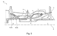
- the invention relates to a gas turbine of the axial flow type, an example of which is shown in Fig. 5 .
- the gas turbine 10 of Fig. 5 operates according to the principle of sequential combustion. It comprises a compressor 1, a first combustion chamber 4 with a plurality of burners 3 and a first fuel supply 2, a high-pressure turbine 5, a second combustion chamber 7 with the second fuel supply 6, and a low-pressure turbine 8 with alternating rows of vanes 13 or 33 and blades 16 or 36, which are arranged in a plurality of turbine stages arranged along the machine axis 9.
- the gas turbine 10 comprises a stator and a rotor.
- the stator includes a housing with the vanes 13, 33 mounted therein; these vanes 13, 33 are necessary to form profiled channels where hot gas developed in the combustion chamber 7 flows through. Gas flowing in the required direction hits against the blades 16, 36 installed in shaft slits of a rotor shaft and makes the turbine rotor to rotate.
- stator heat shields installed between adjacent vane rows are used. High temperature turbine stages require cooling air to be supplied into vanes, stator heat shields and blades.
- FIG. 1 A section of a typical cooled gas turbine stage TS of a gas turbine 10 is shown in Fig. 1 .
- a row of vanes 13 is mounted on a vane carrier 11.
- a row of rotating blades 16 is provided each of which has an outer platform 17 at its tip.
- stator heat shields 18 are mounted on the vane carrier 11.
- Each of the vanes 13 has an outer platform 14.
- the vanes 13 and blades 16 with their respective outer platforms 14 and 17 border a hot gas path 12, through which the hot gases from the combustion chamber flow.
- cooling air 23 is directed through respective cooling bores 21 and 22 from a plenum 20 to the stator heat shields 18 and vanes 13 and hot outer platforms 17 of the blades 16.
- the known turbine design of Fig. 1 requires sufficient additional amount of cooling air 23 to be supplied into a cavity 19 on the back of the stator heat shields 18 to cool those stator heat shields and the outer blade platform 17, and this feature can be considered as a shortcoming of this design.
- Another drawback is the traditional way of stator heat shield fixation where a gap exists between a vane 13 and the stator heat shield 18 (see the encircled zone A in Fig. 1 ), and a portion of cooling air leaks from the cavity 19 through said gap into the turbine flow path 12 (see arrows in the zone A).
- the gas turbine of the invention is of the axial flow type and comprises a rotor with alternating rows of air-cooled blades and air-cooled rotor heat shields, and a stator with alternating rows of air-cooled vanes and air-cooled stator heat shields mounted on a vane carrier, whereby the stator coaxially surrounds the rotor to define a hot gas path in between, such that the rows of blades and stator heat shields, and the rows of vanes and rotor heat shields are correlated with each other, respectively, and a row of vanes and the next row of blades in the downstream direction define a turbine stage.
- within a turbine stage means are provided to reuse the cooling air that has already been used to cool, especially the airfoils of, the vanes of the turbine stage, for cooling the stator heat shields of said turbine stage downstream of the vanes.
- the reusing means comprises first means for collecting the used cooling air when exiting the vanes, and second means for directing the collected used cooling air onto the stator heat shields of said turbine stage downstream of the vanes, for cooling.
- the reusing means further comprises third means for directing the collected used cooling air onto outer platforms of the blades of said turbine stage downstream of the vanes, for cooling.
- the vanes of the turbine stage each comprise an outer platform, and the reusing means are integrated into the vanes just above the outer platforms.
- the collecting means comprises a first cavity for each of the vanes located at the exit of the vane cooling air on the upper side of the outer platform
- the directing means comprises a second cavity extending in the circumferential direction and being connected to said first cavity, whereby a plurality of first axially oriented holes, which are equally distributed along the circumferential direction, direct used cooling air from the second cavity onto the outside of the adjacent stator heat shields of the turbine stage, for cooling.
- a plurality of second axially oriented holes which are equally distributed along the circumferential direction, direct used cooling air from the second cavity onto the outside of the outer platforms of the adjacent blades of the turbine stage, for cooling.
- the outer platforms of the blades of the turbine stage each comprise a circumferentially oriented forward tooth
- the vanes of the turbine stage overlap said forward tooth with a circumferentially extending downstream projection at the rear wall of their outer platform, and each downstream projection is provided with a honeycomb just opposite to the forward tooth.
- the first cavity is established by a rib in form of a frame on the upper side of the outer platform, which frame is covered by a sealing screen.
- the second cavity is established by a recess in the rear wall of the outer platform, which recess is covered by a sealing screen.
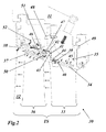
- Fig. 2 presents an embodiment of the proposed high temperature turbine stage design, where cooling air is partly saved due to utilization of air used up in the vanes of the turbine stage.
- the gas turbine 30 of Fig. 2 comprises a turbine stage TS with a row of vanes 33 followed by a row of blades 36.
- the blades 36 are mounted on a rotor, not shown in the Figure.
- the vanes 33 are mounted on a vane carrier 31, which surrounds the rotor to define a hot gas path 32.
- stator heat shields 38 Also mounted on the vane carrier 31 are stator heat shields 38, in opposition to outer platforms 37 at the tips of the blades 36.
- the outer platforms 37 are provided on their outer side with several teeth, each extending in the circumferential direction. One of these teeth, the forward tooth, has the reference numeral 50.
- Air used up in the vane 33 passes from the vane airfoil through the outer platform 34 into a small cavity 39 partitioned off from the basic (outer) platform 34 with a rib 40 (see Figs. 2 and 3 ).
- the air then flows from the cavity 39 into a neighbouring cavity 41, which extends along the circumferential direction, and is distributed into two parallel rows of first and second holes 42 and 43 equally spaced in circumferential direction (see Figs. 2 and 3 ).
- First holes 42 direct jets of used cooling air onto the other side of rotor heat shields 38.
- Second holes 43 direct jets of used cooling air 1 to the forward teeth 50 of the outer blade platforms 37.
- the cavities 39 and 41 are closed with a common sealing screen 44 ( Fig. 4 ).
- Another (perforated) screen 45 is situated above the remaining largest part of the outer platform 34, and air for cooling the platform surface and for passing into the interior of the vane airfoil is through holes of this screen.
- FIG. 2 Another important innovation of the proposed design according to Fig. 2 is the provision of a projection 47 on the rear wall of the outer vane platform 34 (see Figs. 2-4 ).
- This projection 47 is equipped on its lower side with a honeycomb 51.
- the forward tooth 50 of the outer blade platform 37 is situated under the projection 47, and this tooth 50 prevents additional leakages of used-up air from the cavity 46 between outer platform 37 and stator heat shield 38 into the turbine flow path 32.
- Used-up air passes also into a cavity 52 between the vane carrier 31 and stator heat shields 38 through gaps in part joints. Used-up air passing through the second holes 43 serves to protect the forward teeth 50 of the outer blade platforms 37.
Landscapes
- Engineering & Computer Science (AREA)
- Mechanical Engineering (AREA)
- General Engineering & Computer Science (AREA)
- Turbine Rotor Nozzle Sealing (AREA)
Abstract
Description
- The present invention relates to the technology of gas turbines. It refers to a gas turbine of the axial flow type according to the preamble of
claim 1. - The invention relates to a gas turbine of the axial flow type, an example of which is shown in
Fig. 5 . Thegas turbine 10 ofFig. 5 operates according to the principle of sequential combustion. It comprises acompressor 1, a first combustion chamber 4 with a plurality of burners 3 and a first fuel supply 2, a high-pressure turbine 5, a second combustion chamber 7 with the second fuel supply 6, and a low-pressure turbine 8 with alternating rows ofvanes blades - The
gas turbine 10 according toFig. 5 comprises a stator and a rotor. The stator includes a housing with thevanes vanes blades blades - A section of a typical cooled gas turbine stage TS of a
gas turbine 10 is shown inFig. 1 . Within a turbine stage TS of the gas turbine 10 a row ofvanes 13 is mounted on avane carrier 11. Downstream of the vanes 13 a row of rotatingblades 16 is provided each of which has anouter platform 17 at its tip. Opposite to the tips of theblades 16,stator heat shields 18 are mounted on thevane carrier 11. Each of thevanes 13 has anouter platform 14. Thevanes 13 andblades 16 with their respectiveouter platforms hot gas path 12, through which the hot gases from the combustion chamber flow. - To ensure operation of such a high
temperature gas turbine 10 with long-term life time, all parts forming itsflow path 12 should be cooled effectively. Therefore,cooling air 23 is directed throughrespective cooling bores plenum 20 to thestator heat shields 18 andvanes 13 and hotouter platforms 17 of theblades 16. However, the known turbine design ofFig. 1 requires sufficient additional amount ofcooling air 23 to be supplied into acavity 19 on the back of thestator heat shields 18 to cool those stator heat shields and theouter blade platform 17, and this feature can be considered as a shortcoming of this design. Another drawback is the traditional way of stator heat shield fixation where a gap exists between avane 13 and the stator heat shield 18 (see the encircled zone A inFig. 1 ), and a portion of cooling air leaks from thecavity 19 through said gap into the turbine flow path 12 (see arrows in the zone A). - It is an object of the present invention to provide a gas turbine with turbine stage cooling scheme, which avoids the drawbacks of the known cooling configuration and substantially reduces the consumption of cooling air within said turbine stage.
- This and other objects are obtained by a gas turbine according to
claim 1. The gas turbine of the invention is of the axial flow type and comprises a rotor with alternating rows of air-cooled blades and air-cooled rotor heat shields, and a stator with alternating rows of air-cooled vanes and air-cooled stator heat shields mounted on a vane carrier, whereby the stator coaxially surrounds the rotor to define a hot gas path in between, such that the rows of blades and stator heat shields, and the rows of vanes and rotor heat shields are correlated with each other, respectively, and a row of vanes and the next row of blades in the downstream direction define a turbine stage. According to the invention, within a turbine stage means are provided to reuse the cooling air that has already been used to cool, especially the airfoils of, the vanes of the turbine stage, for cooling the stator heat shields of said turbine stage downstream of the vanes. - According to an embodiment of the invention, the reusing means comprises first means for collecting the used cooling air when exiting the vanes, and second means for directing the collected used cooling air onto the stator heat shields of said turbine stage downstream of the vanes, for cooling.
- Preferably, the reusing means further comprises third means for directing the collected used cooling air onto outer platforms of the blades of said turbine stage downstream of the vanes, for cooling.
- According to another embodiment of the invention, the vanes of the turbine stage each comprise an outer platform, and the reusing means are integrated into the vanes just above the outer platforms.
- According to another embodiment, the collecting means comprises a first cavity for each of the vanes located at the exit of the vane cooling air on the upper side of the outer platform, the directing means comprises a second cavity extending in the circumferential direction and being connected to said first cavity, whereby a plurality of first axially oriented holes, which are equally distributed along the circumferential direction, direct used cooling air from the second cavity onto the outside of the adjacent stator heat shields of the turbine stage, for cooling.
- According to just another embodiment of the invention, a plurality of second axially oriented holes, which are equally distributed along the circumferential direction, direct used cooling air from the second cavity onto the outside of the outer platforms of the adjacent blades of the turbine stage, for cooling.
- Preferably, the outer platforms of the blades of the turbine stage each comprise a circumferentially oriented forward tooth, the vanes of the turbine stage overlap said forward tooth with a circumferentially extending downstream projection at the rear wall of their outer platform, and each downstream projection is provided with a honeycomb just opposite to the forward tooth.
- According to another embodiment, the first cavity is established by a rib in form of a frame on the upper side of the outer platform, which frame is covered by a sealing screen.
- According to another embodiment, the second cavity is established by a recess in the rear wall of the outer platform, which recess is covered by a sealing screen.
- The present invention is now to be explained more closely by means of different embodiments and with reference to the attached drawings.
- Fig. 1
- shows cooling details of a turbine stage of a gas turbine according to the prior art;
- Fig. 2
- shows cooling details of a turbine stage of a gas turbine according to an embodiment of the invention;
- Fig. 3
- shows in a perspective view the configuration of the outer platform of the vane of
Fig. 2 in accordance with an embodiment of the invention, whereby all of screens are removed; - Fig. 4
- shows in a perspective view the configuration of the outer platform of the vane of
Fig. 3 with all screens put in place; and - Fig. 5
- shows a well-known basic design of a gas turbine with sequential combustion, which may be used for practising the invention.
-
Fig. 2 presents an embodiment of the proposed high temperature turbine stage design, where cooling air is partly saved due to utilization of air used up in the vanes of the turbine stage. Thegas turbine 30 ofFig. 2 comprises a turbine stage TS with a row ofvanes 33 followed by a row ofblades 36. Theblades 36 are mounted on a rotor, not shown in the Figure. Thevanes 33 are mounted on avane carrier 31, which surrounds the rotor to define ahot gas path 32. Also mounted on thevane carrier 31 arestator heat shields 38, in opposition toouter platforms 37 at the tips of theblades 36. Theouter platforms 37 are provided on their outer side with several teeth, each extending in the circumferential direction. One of these teeth, the forward tooth, has thereference numeral 50. - Air used up in the
vane 33 passes from the vane airfoil through theouter platform 34 into asmall cavity 39 partitioned off from the basic (outer)platform 34 with a rib 40 (seeFigs. 2 and3 ). The air then flows from thecavity 39 into a neighbouringcavity 41, which extends along the circumferential direction, and is distributed into two parallel rows of first andsecond holes Figs. 2 and3 ).First holes 42 direct jets of used cooling air onto the other side ofrotor heat shields 38.Second holes 43 direct jets of usedcooling air 1 to theforward teeth 50 of theouter blade platforms 37. Thecavities Fig. 4 ). Another (perforated)screen 45 is situated above the remaining largest part of theouter platform 34, and air for cooling the platform surface and for passing into the interior of the vane airfoil is through holes of this screen. - The efficient utilization of used-up air described above makes it possible to avoid an additional supply of fresh cooling air to the
stator heat shields 38 and blade shrouds orouter platforms 37. - Another important innovation of the proposed design according to
Fig. 2 is the provision of aprojection 47 on the rear wall of the outer vane platform 34 (seeFigs. 2-4 ). Thisprojection 47 is equipped on its lower side with ahoneycomb 51. Theforward tooth 50 of theouter blade platform 37 is situated under theprojection 47, and thistooth 50 prevents additional leakages of used-up air from thecavity 46 betweenouter platform 37 andstator heat shield 38 into theturbine flow path 32. - When the proposed shape of the
outer vane platform 34 according toFig. 2 is compared with that ofouter Vane platform 14 presented inFig. 1 , it is clear that leakage minimization is also a result of the absence of an additional gap (see zone A marked inFig. 1 ). Thus, used-up air passes without losses through thefirst holes 42 into thecavity 46 between astator heat shield 38 and anouter blade platform 37. This air substantially improves the thermal state of theouter blade platforms 37 and makes it possible to avoid additional air supply for cooling the stator heat shields 38. - Used-up air passes also into a
cavity 52 between thevane carrier 31 andstator heat shields 38 through gaps in part joints. Used-up air passing through thesecond holes 43 serves to protect theforward teeth 50 of theouter blade platforms 37. - With the invention following advantages can be achieved:
- 1. Air used up in a vane is then utilized to cool other parts.
- 2. There is no need to introduce additional air for cooling the stator heat shields.
- 3. The proposed shape of the outer vane platform with an
additional projection 47 on its rear wall makes it possible to avoid additional cooling air leakages through the slit marked by zone A inFig. 1 . - 4. Utilized air fills the cavity 52 (see
Fig. 2 ) and protects thevane carrier 31 against overheating. - Thus, a combination of the vane with
projection 47 at itsouter platform 34 and a separate collector (cavity 39) for utilized air, as well as a combination of a non-cooledstator heat shield 38 and a three-prongedouter blade platform 37 with thecavity 46 formed in between, enables a modern high- performance turbine to be created. -
- 1
- compressor
- 2,6
- fuel supply
- 3
- burner
- 4,7
- combustion chamber
- 5
- high-pressure turbine
- 8
- low-pressure turbine
- 9
- axis
- 10,30
- gas turbine
- 11,31
- vane carrier
- 12,32
- hot gas path
- 13,33
- vane
- 14,34
- outer platform (vane)
- 15,35
- cavity
- 16,36
- blade
- 17,37
- outer platform (blade)
- 18,38
- stator heat shield
- 19
- cavity
- 20
- plenum
- 21,22
- cooling bore
- 23
- cooling air
- 39,41,46,52
- cavity
- 40
- rib
- 42
- hole
- 43
- hole
- 44
- sealing screen
- 45
- screen
- 47
- projection
- 48,49
- hook
- 50
- forward tooth (blade outer platform)
- 51
- honeycomb
- TS
- turbine stage
Claims (9)
- Gas turbine (30) of the axial flow type, comprising a rotor with alternating rows of air-cooled blades (36) and air-cooled rotor heat shields, and a stator with alternating rows of air-cooled vanes (33) and air-cooled stator heat shields (38) mounted on a vane carrier (31), whereby the stator coaxially surrounds the rotor to define a hot gas path (32) in between, such that the rows of blades (36) and stator heat shields (38), and the rows of vanes (33) and rotor heat shields are correlated with each other, respectively, and a row of vanes (33) and the next row of blades (36) in the downstream direction define a turbine stage (TS), characterised in that within a turbine stage (TS) means (39-44) are provided to reuse the cooling air that has already been used to cool, especially the airfoils of, the vanes (33) of the turbine stage (TS), for cooling the stator heat shields (38) of said turbine stage (TS) downstream of the vanes (33).
- Gas turbine according to claim 1, characterised in that the reusing means comprises first means (39, 40, 44) for collecting the used cooling air when exiting the vanes (33), and second means (41, 42, 44) for directing the collected used cooling air onto the stator heat shields (38) of said turbine stage (TS) downstream of the vanes (33), for cooling.
- Gas turbine according to claim 2, characterised in that the reusing means further comprises third means (41, 43, 44) for directing the collected used cooling air onto outer platforms (37) of the blades (36) of said turbine stage (TS) downstream of the vanes (33), for cooling.
- Gas turbine according to one of the claims 1 to 3, characterised in that the vanes (33) of the turbine stage (TS) each comprise an outer platform (34), and the reusing means (39-44) are integrated into the vanes (33) just above the outer platforms (34).
- Gas turbine according to claim 3, characterised in that the collecting means comprises a first cavity (39) for each of the vanes (33) located at the exit of the vane cooling air on the upper side of the outer platform (34), the directing means comprises a second cavity (41) extending in the circumferential direction and being connected to said first cavity (39), whereby a plurality of first axially oriented holes (42), which are equally distributed along the circumferential direction, direct used cooling air from the second cavity (41) onto the outside of the adjacent stator heat shields (38) of the turbine stage (TS), for cooling.
- Gas turbine according to claim 5, characterised in that a plurality of second axially oriented holes (43), which are equally distributed along the circumferential direction, direct used cooling air from the second cavity (41) onto the outside of the outer platforms (37) of the adjacent blades (36) of the turbine stage (TS), for cooling.
- Gas turbine according to claim 6, characterised in that the outer platforms (37) of the blades (36) of the turbine stage (TS) each comprise a circumferentially oriented forward tooth (50), the vanes (33) of the turbine stage (TS) overlap said forward tooth (50) with a circumferentially extending downstream projection (47) at the rear wall of their outer platform (34), and each downstream projection (47) is provided with a honeycomb (51) just opposite to the forward tooth (50).
- Gas turbine according to claim 5, characterised in that said first cavity (39) is established by a rib (40) in form of a frame on the upper side of the outer platform (34), which frame is covered by a sealing screen (44).
- Gas turbine according to claim 5, characterised in that the second cavity (41) is established by a recess in the rear wall of the outer platform (34), which recess is covered by a sealing screen (44).
Applications Claiming Priority (1)
| Application Number | Priority Date | Filing Date | Title |
|---|---|---|---|
| RU2010148728/06A RU2547351C2 (en) | 2010-11-29 | 2010-11-29 | Axial gas turbine |
Publications (2)
| Publication Number | Publication Date |
|---|---|
| EP2458163A2 true EP2458163A2 (en) | 2012-05-30 |
| EP2458163A3 EP2458163A3 (en) | 2014-11-26 |
Family
ID=45033869
Family Applications (1)
| Application Number | Title | Priority Date | Filing Date |
|---|---|---|---|
| EP11190649.1A Withdrawn EP2458163A3 (en) | 2010-11-29 | 2011-11-24 | Gas turbine of the axial flow type |
Country Status (7)
| Country | Link |
|---|---|
| US (1) | US9334754B2 (en) |
| EP (1) | EP2458163A3 (en) |
| JP (1) | JP5743865B2 (en) |
| CN (1) | CN102562169B (en) |
| AU (1) | AU2011250786B2 (en) |
| MY (1) | MY161483A (en) |
| RU (1) | RU2547351C2 (en) |
Cited By (1)
| Publication number | Priority date | Publication date | Assignee | Title |
|---|---|---|---|---|
| EP3075964A1 (en) * | 2015-03-31 | 2016-10-05 | General Electric Company | System for cooling a turbine engine |
Families Citing this family (11)
| Publication number | Priority date | Publication date | Assignee | Title |
|---|---|---|---|---|
| US8961108B2 (en) * | 2012-04-04 | 2015-02-24 | United Technologies Corporation | Cooling system for a turbine vane |
| US20130318996A1 (en) * | 2012-06-01 | 2013-12-05 | General Electric Company | Cooling assembly for a bucket of a turbine system and method of cooling |
| EP2713009B1 (en) | 2012-09-26 | 2015-03-11 | Alstom Technology Ltd | Cooling method and system for cooling blades of at least one blade row in a rotary flow machine |
| EP2949871B1 (en) * | 2014-05-07 | 2017-03-01 | United Technologies Corporation | Variable vane segment |
| US9752446B2 (en) * | 2015-01-09 | 2017-09-05 | United Technologies Corporation | Support buttress |
| US10451084B2 (en) * | 2015-11-16 | 2019-10-22 | General Electric Company | Gas turbine engine with vane having a cooling inlet |
| US10584636B2 (en) * | 2017-01-27 | 2020-03-10 | Mitsubishi Hitachi Power Systems Americas, Inc. | Debris filter apparatus for preventing clogging of turbine vane cooling holes |
| US10941709B2 (en) * | 2018-09-28 | 2021-03-09 | Pratt & Whitney Canada Corp. | Gas turbine engine and cooling air configuration for turbine section thereof |
| US11492914B1 (en) * | 2019-11-08 | 2022-11-08 | Raytheon Technologies Corporation | Engine with cooling passage circuit for air prior to ceramic component |
| US12098656B2 (en) * | 2021-03-23 | 2024-09-24 | Mitsubishi Heavy Industries, Ltd. | Stator vane assembly of gas turbine, stationary member segment, and method of producing stator vane assembly of gas turbine |
| CN114856716A (en) * | 2022-06-02 | 2022-08-05 | 中国联合重型燃气轮机技术有限公司 | Turbine blade, gas turbine and aircraft engine with a plurality of L-shaped cooling channels |
Citations (1)
| Publication number | Priority date | Publication date | Assignee | Title |
|---|---|---|---|---|
| US20040258523A1 (en) * | 2001-12-13 | 2004-12-23 | Shailendra Naik | Sealing assembly |
Family Cites Families (43)
| Publication number | Priority date | Publication date | Assignee | Title |
|---|---|---|---|---|
| NL202529A (en) | 1954-12-16 | |||
| BE755567A (en) * | 1969-12-01 | 1971-02-15 | Gen Electric | FIXED VANE STRUCTURE, FOR GAS TURBINE ENGINE AND ASSOCIATED TEMPERATURE ADJUSTMENT ARRANGEMENT |
| FR2280791A1 (en) * | 1974-07-31 | 1976-02-27 | Snecma | IMPROVEMENTS IN ADJUSTING THE CLEARANCE BETWEEN THE BLADES AND THE STATOR OF A TURBINE |
| GB1484288A (en) * | 1975-12-03 | 1977-09-01 | Rolls Royce | Gas turbine engines |
| US4311431A (en) * | 1978-11-08 | 1982-01-19 | Teledyne Industries, Inc. | Turbine engine with shroud cooling means |
| US4280792A (en) * | 1979-02-09 | 1981-07-28 | Avco Corporation | Air-cooled turbine rotor shroud with restraints |
| US4693667A (en) * | 1980-04-29 | 1987-09-15 | Teledyne Industries, Inc. | Turbine inlet nozzle with cooling means |
| US4573865A (en) * | 1981-08-31 | 1986-03-04 | General Electric Company | Multiple-impingement cooled structure |
| FR2519374B1 (en) * | 1982-01-07 | 1986-01-24 | Snecma | DEVICE FOR COOLING THE HEELS OF MOBILE BLADES OF A TURBINE |
| GB2170867B (en) * | 1985-02-12 | 1988-12-07 | Rolls Royce | Improvements in or relating to gas turbine engines |
| JP2862536B2 (en) * | 1987-09-25 | 1999-03-03 | 株式会社東芝 | Gas turbine blades |
| US5344283A (en) * | 1993-01-21 | 1994-09-06 | United Technologies Corporation | Turbine vane having dedicated inner platform cooling |
| GB9305010D0 (en) * | 1993-03-11 | 1993-04-28 | Rolls Royce Plc | A cooled turbine nozzle assembly and a method of calculating the diameters of cooling holes for use in such an assembly |
| JP3727701B2 (en) | 1995-12-27 | 2005-12-14 | 三菱重工業株式会社 | Gas turbine blade cooling system |
| GB2313161B (en) * | 1996-05-14 | 2000-05-31 | Rolls Royce Plc | Gas turbine engine casing |
| GB2313414B (en) * | 1996-05-24 | 2000-05-17 | Rolls Royce Plc | Gas turbine engine blade tip clearance control |
| JP3495579B2 (en) * | 1997-10-28 | 2004-02-09 | 三菱重工業株式会社 | Gas turbine stationary blade |
| GB9725623D0 (en) * | 1997-12-03 | 2006-09-20 | Rolls Royce Plc | Improvements in or relating to a blade tip clearance system |
| DE19756734A1 (en) * | 1997-12-19 | 1999-06-24 | Bmw Rolls Royce Gmbh | Passive gap system of a gas turbine |
| US5993150A (en) * | 1998-01-16 | 1999-11-30 | General Electric Company | Dual cooled shroud |
| GB9815611D0 (en) * | 1998-07-18 | 1998-09-16 | Rolls Royce Plc | Improvements in or relating to turbine cooling |
| RU2210672C2 (en) * | 1998-09-10 | 2003-08-20 | Алстом | Device for cooling over-rotor surfaces of turbine nozzle assembly |
| US6435813B1 (en) * | 2000-05-10 | 2002-08-20 | General Electric Company | Impigement cooled airfoil |
| GB0029337D0 (en) * | 2000-12-01 | 2001-01-17 | Rolls Royce Plc | A seal segment for a turbine |
| US6431820B1 (en) * | 2001-02-28 | 2002-08-13 | General Electric Company | Methods and apparatus for cooling gas turbine engine blade tips |
| EP1245806B1 (en) * | 2001-03-30 | 2005-08-03 | Siemens Aktiengesellschaft | Cooled gas turbine balde |
| ES2239082T3 (en) * | 2001-08-09 | 2005-09-16 | Siemens Aktiengesellschaft | GAS TURBINE AND PROCEDURE FOR THE OPERATION OF A GAS TURBINE. |
| GB2378730B (en) * | 2001-08-18 | 2005-03-16 | Rolls Royce Plc | Cooled segments surrounding turbine blades |
| DE10156193A1 (en) * | 2001-11-15 | 2003-06-05 | Alstom Switzerland Ltd | Heat shield for gas turbine stator, has arrangement on shield to prevent hot air turbulence form forming in hollow volume upstream of first arrangement for preventing hot air flow. |
| JP2005513330A (en) * | 2001-12-13 | 2005-05-12 | アルストム テクノロジー リミテッド | High-temperature gas flow path structure of gas turbine |
| US6779597B2 (en) * | 2002-01-16 | 2004-08-24 | General Electric Company | Multiple impingement cooled structure |
| US7097418B2 (en) * | 2004-06-18 | 2006-08-29 | Pratt & Whitney Canada Corp. | Double impingement vane platform cooling |
| EP1657407B1 (en) * | 2004-11-15 | 2011-12-28 | Rolls-Royce Deutschland Ltd & Co KG | Method for the cooling of the outer shrouds of the rotor blades of a gas turbine |
| US7246989B2 (en) * | 2004-12-10 | 2007-07-24 | Pratt & Whitney Canada Corp. | Shroud leading edge cooling |
| FR2899281B1 (en) * | 2006-03-30 | 2012-08-10 | Snecma | DEVICE FOR COOLING A TURBINE HOUSING OF A TURBOMACHINE |
| US7611324B2 (en) * | 2006-11-30 | 2009-11-03 | General Electric Company | Method and system to facilitate enhanced local cooling of turbine engines |
| US7690885B2 (en) * | 2006-11-30 | 2010-04-06 | General Electric Company | Methods and system for shielding cooling air to facilitate cooling integral turbine nozzle and shroud assemblies |
| US7604453B2 (en) * | 2006-11-30 | 2009-10-20 | General Electric Company | Methods and system for recuperated circumferential cooling of integral turbine nozzle and shroud assemblies |
| US7862291B2 (en) * | 2007-02-08 | 2011-01-04 | United Technologies Corporation | Gas turbine engine component cooling scheme |
| ATE472046T1 (en) * | 2007-09-24 | 2010-07-15 | Alstom Technology Ltd | SEAL IN GAS TURBINE |
| RU2355890C1 (en) * | 2007-11-29 | 2009-05-20 | Открытое акционерное общество "Авиадвигатель" | High-temperature multi-stage gas turbine |
| US7946801B2 (en) | 2007-12-27 | 2011-05-24 | General Electric Company | Multi-source gas turbine cooling |
| FR2954401B1 (en) * | 2009-12-23 | 2012-03-23 | Turbomeca | METHOD FOR COOLING TURBINE STATORS AND COOLING SYSTEM FOR ITS IMPLEMENTATION |
-
2010
- 2010-11-29 RU RU2010148728/06A patent/RU2547351C2/en not_active IP Right Cessation
-
2011
- 2011-11-15 AU AU2011250786A patent/AU2011250786B2/en not_active Ceased
- 2011-11-22 MY MYPI2011005637A patent/MY161483A/en unknown
- 2011-11-24 EP EP11190649.1A patent/EP2458163A3/en not_active Withdrawn
- 2011-11-29 US US13/306,072 patent/US9334754B2/en not_active Expired - Fee Related
- 2011-11-29 JP JP2011260781A patent/JP5743865B2/en not_active Expired - Fee Related
- 2011-11-29 CN CN201110407973.3A patent/CN102562169B/en not_active Expired - Fee Related
Patent Citations (1)
| Publication number | Priority date | Publication date | Assignee | Title |
|---|---|---|---|---|
| US20040258523A1 (en) * | 2001-12-13 | 2004-12-23 | Shailendra Naik | Sealing assembly |
Cited By (2)
| Publication number | Priority date | Publication date | Assignee | Title |
|---|---|---|---|---|
| EP3075964A1 (en) * | 2015-03-31 | 2016-10-05 | General Electric Company | System for cooling a turbine engine |
| US10400627B2 (en) | 2015-03-31 | 2019-09-03 | General Electric Company | System for cooling a turbine engine |
Also Published As
| Publication number | Publication date |
|---|---|
| JP2012117537A (en) | 2012-06-21 |
| AU2011250786A1 (en) | 2012-06-14 |
| CN102562169B (en) | 2015-04-08 |
| MY161483A (en) | 2017-04-14 |
| US9334754B2 (en) | 2016-05-10 |
| AU2011250786B2 (en) | 2016-01-21 |
| EP2458163A3 (en) | 2014-11-26 |
| RU2010148728A (en) | 2012-06-10 |
| RU2547351C2 (en) | 2015-04-10 |
| JP5743865B2 (en) | 2015-07-01 |
| US20120134781A1 (en) | 2012-05-31 |
| CN102562169A (en) | 2012-07-11 |
Similar Documents
| Publication | Publication Date | Title |
|---|---|---|
| AU2011250786B2 (en) | Gas turbine of the axial flow type | |
| EP2458152B1 (en) | Gas turbine of the axial flow type | |
| US8157505B2 (en) | Turbine blade with single tip rail with a mid-positioned deflector portion | |
| EP2458159A1 (en) | Gas turbine of the axial flow type | |
| EP2458155B1 (en) | Gas turbine of the axial flow type | |
| US9845687B2 (en) | Gas turbine engine component having platform cooling channel | |
| EP3047111B1 (en) | Component for a gas turbine engine, corresponding gas turbine engine and method of cooling | |
| JP2002317602A (en) | gas turbine | |
| EP2713009B1 (en) | Cooling method and system for cooling blades of at least one blade row in a rotary flow machine | |
| EP3392566B1 (en) | Combustor panel cooling arrangements | |
| WO2017003455A1 (en) | Turbine stator vane cooling circuit with flow stream separation |
Legal Events
| Date | Code | Title | Description |
|---|---|---|---|
| PUAI | Public reference made under article 153(3) epc to a published international application that has entered the european phase |
Free format text: ORIGINAL CODE: 0009012 |
|
| AK | Designated contracting states |
Kind code of ref document: A2 Designated state(s): AL AT BE BG CH CY CZ DE DK EE ES FI FR GB GR HR HU IE IS IT LI LT LU LV MC MK MT NL NO PL PT RO RS SE SI SK SM TR |
|
| AX | Request for extension of the european patent |
Extension state: BA ME |
|
| PUAL | Search report despatched |
Free format text: ORIGINAL CODE: 0009013 |
|
| AK | Designated contracting states |
Kind code of ref document: A3 Designated state(s): AL AT BE BG CH CY CZ DE DK EE ES FI FR GB GR HR HU IE IS IT LI LT LU LV MC MK MT NL NO PL PT RO RS SE SI SK SM TR |
|
| AX | Request for extension of the european patent |
Extension state: BA ME |
|
| RIC1 | Information provided on ipc code assigned before grant |
Ipc: F01D 25/12 20060101AFI20141023BHEP |
|
| 17P | Request for examination filed |
Effective date: 20150129 |
|
| RBV | Designated contracting states (corrected) |
Designated state(s): AL AT BE BG CH CY CZ DE DK EE ES FI FR GB GR HR HU IE IS IT LI LT LU LV MC MK MT NL NO PL PT RO RS SE SI SK SM TR |
|
| RAP1 | Party data changed (applicant data changed or rights of an application transferred) |
Owner name: GENERAL ELECTRIC TECHNOLOGY GMBH |
|
| 17Q | First examination report despatched |
Effective date: 20161020 |
|
| RIC1 | Information provided on ipc code assigned before grant |
Ipc: F01D 5/18 20060101ALI20180711BHEP Ipc: F01D 25/12 20060101AFI20180711BHEP |
|
| GRAP | Despatch of communication of intention to grant a patent |
Free format text: ORIGINAL CODE: EPIDOSNIGR1 |
|
| INTG | Intention to grant announced |
Effective date: 20180820 |
|
| STAA | Information on the status of an ep patent application or granted ep patent |
Free format text: STATUS: THE APPLICATION IS DEEMED TO BE WITHDRAWN |
|
| 18D | Application deemed to be withdrawn |
Effective date: 20190103 |