EP2458151A2 - Blade for a gas turbine, method for manufacturing said blade and gas turbine with such a blade - Google Patents
Blade for a gas turbine, method for manufacturing said blade and gas turbine with such a blade Download PDFInfo
- Publication number
- EP2458151A2 EP2458151A2 EP20110190898 EP11190898A EP2458151A2 EP 2458151 A2 EP2458151 A2 EP 2458151A2 EP 20110190898 EP20110190898 EP 20110190898 EP 11190898 A EP11190898 A EP 11190898A EP 2458151 A2 EP2458151 A2 EP 2458151A2
- Authority
- EP
- European Patent Office
- Prior art keywords
- blade
- insert
- channel
- cooling
- cooling air
- Prior art date
- Legal status (The legal status is an assumption and is not a legal conclusion. Google has not performed a legal analysis and makes no representation as to the accuracy of the status listed.)
- Granted
Links
Images


Classifications
-
- F—MECHANICAL ENGINEERING; LIGHTING; HEATING; WEAPONS; BLASTING
- F01—MACHINES OR ENGINES IN GENERAL; ENGINE PLANTS IN GENERAL; STEAM ENGINES
- F01D—NON-POSITIVE DISPLACEMENT MACHINES OR ENGINES, e.g. STEAM TURBINES
- F01D5/00—Blades; Blade-carrying members; Heating, heat-insulating, cooling or antivibration means on the blades or the members
- F01D5/12—Blades
- F01D5/14—Form or construction
- F01D5/18—Hollow blades, i.e. blades with cooling or heating channels or cavities; Heating, heat-insulating or cooling means on blades
- F01D5/187—Convection cooling
-
- F—MECHANICAL ENGINEERING; LIGHTING; HEATING; WEAPONS; BLASTING
- F01—MACHINES OR ENGINES IN GENERAL; ENGINE PLANTS IN GENERAL; STEAM ENGINES
- F01D—NON-POSITIVE DISPLACEMENT MACHINES OR ENGINES, e.g. STEAM TURBINES
- F01D5/00—Blades; Blade-carrying members; Heating, heat-insulating, cooling or antivibration means on the blades or the members
- F01D5/02—Blade-carrying members, e.g. rotors
- F01D5/08—Heating, heat-insulating or cooling means
- F01D5/081—Cooling fluid being directed on the side of the rotor disc or at the roots of the blades
-
- F—MECHANICAL ENGINEERING; LIGHTING; HEATING; WEAPONS; BLASTING
- F05—INDEXING SCHEMES RELATING TO ENGINES OR PUMPS IN VARIOUS SUBCLASSES OF CLASSES F01-F04
- F05D—INDEXING SCHEME FOR ASPECTS RELATING TO NON-POSITIVE-DISPLACEMENT MACHINES OR ENGINES, GAS-TURBINES OR JET-PROPULSION PLANTS
- F05D2230/00—Manufacture
- F05D2230/20—Manufacture essentially without removing material
- F05D2230/21—Manufacture essentially without removing material by casting
-
- Y—GENERAL TAGGING OF NEW TECHNOLOGICAL DEVELOPMENTS; GENERAL TAGGING OF CROSS-SECTIONAL TECHNOLOGIES SPANNING OVER SEVERAL SECTIONS OF THE IPC; TECHNICAL SUBJECTS COVERED BY FORMER USPC CROSS-REFERENCE ART COLLECTIONS [XRACs] AND DIGESTS
- Y10—TECHNICAL SUBJECTS COVERED BY FORMER USPC
- Y10T—TECHNICAL SUBJECTS COVERED BY FORMER US CLASSIFICATION
- Y10T29/00—Metal working
- Y10T29/49—Method of mechanical manufacture
- Y10T29/49316—Impeller making
- Y10T29/49336—Blade making
- Y10T29/49339—Hollow blade
- Y10T29/49341—Hollow blade with cooling passage
- Y10T29/49343—Passage contains tubular insert
Definitions
- the present invention relates to the technology of gas turbines. It refers to a blade for a gas turbine according to the preamble of claim 1.
- the invention relates to designing rotor blades of an axial-flow turbine used in a gas turbine unit.
- the turbine rotor comprises a rotating shaft with axial fir-tree type slots where several blade rows and several rotor heat shields are installed alternately one after another.
- the schematised section of a gas turbine stage is shown in Fig. 1 .
- the turbine 10 of Fig. 1 comprises a stator 12 and a rotor 11.
- the stator 12 represents a housing and comprises a vane carrier 15 with stator heat shields S1-S3 and vanes V1-V3 mounted therein.
- the stator 12 concentrically surrounds the rotor 11 and defines a hot gas path 13.
- Hot gas 16 generated in a combustion chamber passes through profiled channels between the vanes V1-V3, hits against blades B1-B3 mounted in shaft slots of a rotor shaft 14, and thus makes the turbine rotor 11 rotate.
- Inner platforms 23 of the 1 st, 2nd and 3rd stage blades B1, B2 and B3 in combination with intermediate rotor heat shields R1, R2 form the inner outline of the turbine flow or hot gas path 13, which separates the cavity of rotor cooling air transit (cooling air 17) from the hot gas flow 16.
- sealing plates 29 are installed.
- cooling air 17 in this design flows in axial direction along a common flow path between blade roots 24 and rotor heat shields R1, R2 and enters in turn into the internal cavity (cooling channels) of the blade B1, then into that of the blade B2 and that of blade B3 (cooling air 18).
- Turbine blades used in present day efficient gas turbine units are operated under high temperatures with minimum possible air supply. Striving towards cooling air saving results in complication of internal blade channel configurations. Therefore blade manufacturing process is very complicate. After blade casting a problem frequently occurs consisting in elimination (etching out) of a ceramic (casting) core from the blade internal cavity (cooling channels).
- Fig. 2 and 3 show the external configuration and internal channel geometry, respectively, of a typical gas turbine blade according to the state of the art.
- the blade 19 comprises an airfoil 20 with a leading edge 21 and trailing edge 22, and a blade root 24 with an inlet 25 for supplying the internal cooling channel structure ( Fig. 3 ) with cooling air.
- Blade root 24 and airfoil 20 are separated by a platform 23.
- the internal cooling channel structure comprises a plurality of cooling channels 20 and 27a-c, which extend in the longitudinal direction of the blade 19. Usually, some parallel cooling channels 27a-c are connected in series to build one meandering channel, as is shown in Fig. 3 .
- Such a meandering channel 27a-c results in a blind tube or dead end zone 28, which rules out any possibility that a liquid flow-through could be established to remove (by wet etching) ceramic core rests from there; this fact makes the manufacturing process more expensive and sets up a danger concerning the presence of detrimental remains of the core in internal blade channels.
- the inventive blade comprises an airfoil extending along a longitudinal direction, and a blade root for mounting said blade on a rotor shaft of said gas turbine, whereby said airfoil of said blade is provided with cooling channels in the interior thereof, which cooling channels preferably extend along the longitudinal direction and can be supplied with cooling air through cooling air supply means arranged within said blade root.
- said blade root is provided with a blade channel running transversely through said blade root and being spaciously connected to said cooling channels, and an insert is inserted into said blade channel for determining the final configuration and characteristics of the connections between said blade channel and said cooling channels.
- the proposed blade design with an insert and connecting means in it allows cooling air leaks to be reduced, blade reliability and life time to be increased, and turbine efficiency to be improved.
- said blade channel is a cylindrical channel
- the insert is of a tubular configuration such that it fits exactly into said cylindrical channel
- the insert has at least one nozzle in its wall, through which one of said cooling channels is connected to said blade channel, and which determines the mass flow of cooling air entering said one cooling channel.
- adjacent of said cooling channels are separated by a wall but connected via said blade channel, and said insert is configured to close said connection between said adjacent cooling channels.
- cooling air is supplied to said insert at one end.
- cooling air exits said insert at the other end.
- said cooling air exits said insert at the other end through a nozzle.
- said insert is closed at the other end, especially by means of a plug.
- said insert is brazed to said blade.
- the inventive method for manufacturing a blade is characterized in that in a first step the blade is formed by means of a casting process, whereby a core is used to form said cooling channels within the airfoil of said blade, in a second step said blade channel is machined into the blade root of said blade, in a third step said core is removed from the interior of said blade, preferably by a wet etching process, and in a fourth step the insert is inserted into said blade channel.
- said insert is fixed to said blade, especially by brazing.
- the gas turbine according to the invention comprises a rotor with a plurality of blades, which are mounted to a rotor shaft and are supplied with cooling air through said rotor shaft, whereby the said blades are blades according to the invention.
- a blade design is proposed where a (preferably tubular) insert is provided in a horizontal blade channel for configuring and determining cooling air supply.
- a (preferably tubular) insert is provided in a horizontal blade channel for configuring and determining cooling air supply.
- An embodiment of this design is demonstrated in Fig. 4 .
- a blade 30 with an airfoil 31 and a blade root 32 is provided with cooling channels 33 and 35 running along a longitudinal direction of the blade 30 through the interior of the airfoil 31.
- the cooling channels 33, 35 open at their lower ends into respective cavities 34 and 36, which are separated from each other by a wall 38 and from the outside by walls 37 and 39.
- a cylindrical blade channel 40 runs transversely through the blade root 32, thereby connecting the cavities 34 and 36 and allowing broad access to all of the cooling channels 33, 35.
- a tubular insert 41 which fits exactly into the cylindrical blade channel 40, is inserted into blade channel 40.
- the insert 41 receives at its one end a cooling air flow 45 and directs it into cooling channel 33 by means of a nozzle or opening 42 provided in its wall.
- a suitable plug 43 closes the insert 41 such that all of cooling air entering the insert 41 flows into the one cooling channel 33.
- the other cooling channels (35 in this case) thus receive their cooling air via the cooling channel 33.
- the basic advantage of the proposed design stems from the tubular insert 41 with its vertical nozzle 42 (see Fig. 5 ) installed in the cylindrical blade channel 40.
- cavities 34 and 36 Prior to installation of the insert 41, cavities 34 and 36 are open for access in a technological process comprising the etching-off of the ceramic core, which has been used for casting the blade; in this case, a flow-through of an etching liquid (liquid flow 44) is ensured to be performed freely in any direction (see Fig. 4 ).
- the tubular insert 41 is installed, thereby separating cavities 34 and 36 at the wall 38, since it is inadmissible for cavities 34 and 36 to be joined during blade operation within the gas turbine unit (see Figures 5 , 6 ).
- An advantageous feature of this proposal is the cylindrical shape chosen for the insert, because in this case a minimum gap between the insert 41 and walls 37, 38 and 39 separating the cavities 34, 36 and the outside can be achieved in the simplest way due to machining matching surfaces of both blade 30 and insert 41 with high accuracy.
- Another, important feature of the proposed insert 41 is the possibility for adjusting the flow-through area of the nozzle 42.
- the nozzle 42 is used to supply a required amount of cooling air into the blade cavity 34 and cooling channel 33, respectively.
- an insert 41" can be provided in blade 30" with several nozzles 42 and 42'.
- the outlet of the insert 41 can be provided with a plug 43 (see Fig. 5 or 6 ) or a nozzle 47 (see insert 41" in blade 30" in Fig. 8 ) depending on the rotor cooling scheme.
- the insert can also be used for mere separation of internal blade cavities without an additional nozzle (hole), which ensures cooling air supply into vertical blade channels (see Fig. 7 , insert 41' in blade 30').
- the insert 41, 41' or 41" should preferably be brazed to the blade 30, 30' or 30" to avoid any displacement, since, if the former was cranked or displaced, air supplying nozzles 42 or 42' could be partially closed or shut off.
- the proposed blade design with cylindrical tubular insert and vertical holes in it allows cooling air leaks to be reduced, blade reliability and life time to be increased, and turbine efficiency to be improved.
Landscapes
- Engineering & Computer Science (AREA)
- Mechanical Engineering (AREA)
- General Engineering & Computer Science (AREA)
- Turbine Rotor Nozzle Sealing (AREA)
Abstract
Description
- The present invention relates to the technology of gas turbines. It refers to a blade for a gas turbine according to the preamble of
claim 1. - Especially, the invention relates to designing rotor blades of an axial-flow turbine used in a gas turbine unit. The turbine rotor comprises a rotating shaft with axial fir-tree type slots where several blade rows and several rotor heat shields are installed alternately one after another.
- The schematised section of a gas turbine stage is shown in
Fig. 1 . Theturbine 10 ofFig. 1 comprises astator 12 and arotor 11. Thestator 12 represents a housing and comprises avane carrier 15 with stator heat shields S1-S3 and vanes V1-V3 mounted therein. Thestator 12 concentrically surrounds therotor 11 and defines ahot gas path 13.Hot gas 16 generated in a combustion chamber (not shown) passes through profiled channels between the vanes V1-V3, hits against blades B1-B3 mounted in shaft slots of arotor shaft 14, and thus makes theturbine rotor 11 rotate. -
Inner platforms 23 of the 1 st, 2nd and 3rd stage blades B1, B2 and B3 in combination with intermediate rotor heat shields R1, R2 form the inner outline of the turbine flow orhot gas path 13, which separates the cavity of rotor cooling air transit (cooling air 17) from thehot gas flow 16. To improve tightness of the cooling air flow path between adjacent blades in the circumferential direction,sealing plates 29 are installed. When cooling therotor shaft 14, coolingair 17 in this design flows in axial direction along a common flow path betweenblade roots 24 and rotor heat shields R1, R2 and enters in turn into the internal cavity (cooling channels) of the blade B1, then into that of the blade B2 and that of blade B3 (cooling air 18). - Turbine blades used in present day efficient gas turbine units are operated under high temperatures with minimum possible air supply. Striving towards cooling air saving results in complication of internal blade channel configurations. Therefore blade manufacturing process is very complicate. After blade casting a problem frequently occurs consisting in elimination (etching out) of a ceramic (casting) core from the blade internal cavity (cooling channels).
-
Fig. 2 and 3 show the external configuration and internal channel geometry, respectively, of a typical gas turbine blade according to the state of the art. Theblade 19 comprises anairfoil 20 with a leadingedge 21 andtrailing edge 22, and ablade root 24 with aninlet 25 for supplying the internal cooling channel structure (Fig. 3 ) with cooling air.Blade root 24 andairfoil 20 are separated by aplatform 23. The internal cooling channel structure comprises a plurality ofcooling channels blade 19. Usually, someparallel cooling channels 27a-c are connected in series to build one meandering channel, as is shown inFig. 3 . Such ameandering channel 27a-c results in a blind tube ordead end zone 28, which rules out any possibility that a liquid flow-through could be established to remove (by wet etching) ceramic core rests from there; this fact makes the manufacturing process more expensive and sets up a danger concerning the presence of detrimental remains of the core in internal blade channels. - If the blade cooling scheme of the gas turbine blade in question cannot be simplified without generating significant cooling air losses, then a technological possibility for a guaranteed and complete removal of the ceramic core from the internal blade cavity should be provided.
- It is an object of the present invention to disclose a blade for a gas turbine, which avoids the disadvantages of the known blades and allows realizing complicated cooling channel geometries and optimized cooling air distribution and supply without sacrificing the simplicity of manufacturing of the blade.
- It is another object of the invention to disclose a method for manufacturing such a blade.
- It is a further object of the invention to disclose a gas turbine with such blades.
- These and other objects are obtained by a blade according to
claim 1, a method according toclaim 10, and a gas turbine according toclaim 12. - The inventive blade comprises an airfoil extending along a longitudinal direction, and a blade root for mounting said blade on a rotor shaft of said gas turbine, whereby said airfoil of said blade is provided with cooling channels in the interior thereof, which cooling channels preferably extend along the longitudinal direction and can be supplied with cooling air through cooling air supply means arranged within said blade root.
- According to the invention said blade root is provided with a blade channel running transversely through said blade root and being spaciously connected to said cooling channels, and an insert is inserted into said blade channel for determining the final configuration and characteristics of the connections between said blade channel and said cooling channels.
- The proposed blade design with an insert and connecting means in it allows cooling air leaks to be reduced, blade reliability and life time to be increased, and turbine efficiency to be improved.
- According to an embodiment of the invention said blade channel is a cylindrical channel, and the insert is of a tubular configuration such that it fits exactly into said cylindrical channel.
- Especially, the insert has at least one nozzle in its wall, through which one of said cooling channels is connected to said blade channel, and which determines the mass flow of cooling air entering said one cooling channel.
- According to another embodiment of the invention adjacent of said cooling channels are separated by a wall but connected via said blade channel, and said insert is configured to close said connection between said adjacent cooling channels.
- According to another embodiment cooling air is supplied to said insert at one end.
- According to another embodiment of the invention cooling air exits said insert at the other end.
- Especially, said cooling air exits said insert at the other end through a nozzle.
- According to another embodiment said insert is closed at the other end, especially by means of a plug.
- According to adjust another embodiment of the invention said insert is brazed to said blade.
- The inventive method for manufacturing a blade according is characterized in that in a first step the blade is formed by means of a casting process, whereby a core is used to form said cooling channels within the airfoil of said blade, in a second step said blade channel is machined into the blade root of said blade, in a third step said core is removed from the interior of said blade, preferably by a wet etching process, and in a fourth step the insert is inserted into said blade channel.
- According to an embodiment of the inventive method in a fifth step said insert is fixed to said blade, especially by brazing.
- The gas turbine according to the invention comprises a rotor with a plurality of blades, which are mounted to a rotor shaft and are supplied with cooling air through said rotor shaft, whereby the said blades are blades according to the invention.
- The present invention is now to be explained more closely by means of different embodiments and with reference to the attached drawings.
- Fig. 1
- shows a schematised section of a gas turbine stage, which can be used to realise the invention;
- Fig. 2
- shows the external configuration of a typical gas turbine blade according to the state of the art;
- Fig. 3
- shows the internal channel geometry of a typical gas turbine blade according to
Fig. 2 ; - Fig. 4
- shows a blade according to an embodiment of the invention with its blade channel, but without an insert;
- Fig. 5
- shows the blade of
Fig. 4 with an insert put into the blade channel; - Fig. 6
- shows the blade of
Fig. 5 in a perspective view; - Fig. 7
- shows another embodiment of the inventive blade with a different insert in a perspective view; and
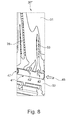
- Fig. 8
- shows in a perspective view another embodiment of the inventive blade with an insert, which is open at both ends.
- To solve the problem mentioned in the introductory part, a blade design is proposed where a (preferably tubular) insert is provided in a horizontal blade channel for configuring and determining cooling air supply. An embodiment of this design is demonstrated in
Fig. 4 . - According to this embodiment, a
blade 30 with anairfoil 31 and ablade root 32 is provided withcooling channels blade 30 through the interior of theairfoil 31. The coolingchannels respective cavities wall 38 and from the outside bywalls cylindrical blade channel 40 runs transversely through theblade root 32, thereby connecting thecavities cooling channels - As can be seen in
Fig. 5 , atubular insert 41, which fits exactly into thecylindrical blade channel 40, is inserted intoblade channel 40. Theinsert 41 receives at its one end a coolingair flow 45 and directs it into coolingchannel 33 by means of a nozzle or opening 42 provided in its wall. At the other end of the insert 41 asuitable plug 43 closes theinsert 41 such that all of cooling air entering theinsert 41 flows into the onecooling channel 33. The other cooling channels (35 in this case) thus receive their cooling air via the coolingchannel 33. - The basic advantage of the proposed design stems from the
tubular insert 41 with its vertical nozzle 42 (seeFig. 5 ) installed in thecylindrical blade channel 40. Prior to installation of theinsert 41,cavities Fig. 4 ). After etching out the ceramic core, thetubular insert 41 is installed, thereby separatingcavities wall 38, since it is inadmissible forcavities Figures 5 ,6 ). - An advantageous feature of this proposal is the cylindrical shape chosen for the insert, because in this case a minimum gap between the
insert 41 andwalls cavities blade 30 and insert 41 with high accuracy. - Another, important feature of the proposed
insert 41 is the possibility for adjusting the flow-through area of thenozzle 42. Thenozzle 42 is used to supply a required amount of cooling air into theblade cavity 34 and coolingchannel 33, respectively. - If more than one cooling channel is necessary to supply air into the
blade 30, then, in accordance withFig. 8 , aninsert 41" can be provided inblade 30" withseveral nozzles 42 and 42'. - The outlet of the
insert 41 can be provided with a plug 43 (seeFig. 5 or6 ) or a nozzle 47 (seeinsert 41" inblade 30" inFig. 8 ) depending on the rotor cooling scheme. The insert can also be used for mere separation of internal blade cavities without an additional nozzle (hole), which ensures cooling air supply into vertical blade channels (seeFig. 7 , insert 41' in blade 30'). - The
insert blade air supplying nozzles 42 or 42' could be partially closed or shut off. - The advantages of the proposed design are:
- 1. Cooling air overflows between internal blade channels are precluded. This improves blade cooling stability and reliability sufficiently (due to precise machining of matched part surfaces).
- 2. Cooling air leakages from the blade supply channel into the turbine flow path are eliminated (due to precise machining of matched part surfaces).
- 3. When required, nozzle flow-through area at the internal blade channel inlet (
nozzle Figs. 6, 7 ,8 ). - 4. When required, nozzle flow-through area at the insert inlet or outlet (nozzle 47) can be adjusted easily by insert change or nozzle change (see
Figs. 6 ,8 ). - 5. The cooling channel configuration can be optimized independent of the process requirements with respect to removal of the casting core.
- In summary, the proposed blade design with cylindrical tubular insert and vertical holes in it allows cooling air leaks to be reduced, blade reliability and life time to be increased, and turbine efficiency to be improved.
-
- 10
- gas turbine
- 11
- rotor
- 12
- stator
- 13
- hot gas path
- 14
- rotor shaft
- 15
- vane carrier
- 16
- hot gas
- 17
- cooling air (main flow)
- 18
- cooling air (entering blades)
- 19,B1-B3
- blade
- 20
- airfoil
- 21
- leading edge
- 22
- trailing edge
- 23
- platform
- 24
- blade root
- 25
- inlet
- 26
- cooling channel
- 27a-c
- cooling channel
- 28
- dead end zone
- 29
- sealing plate
- 30,30',30"
- blade
- 31
- airfoil
- 32
- blade root
- 33,35
- cooling channel
- 34,36
- cavity
- 37,38,39,46
- wall
- 40
- blade channel (cylindrical)
- 41,41',41"
- insert (tubular)
- 42,42',47
- nozzle (opening)
- 43
- plug
- 44
- liquid flow
- 45
- cooling air flow
- R1,R2
- rotor heat shield
- S1-S3
- tator heat shield
- V1-V3
- vane
Claims (12)
- Blade (30, 30', 30") for a gas turbine (10), comprising an airfoil (31) extending along a longitudinal direction, and a blade root (32) for mounting said blade (30, 30', 30") on a rotor shaft (14) of said gas turbine (10), whereby said airfoil (31) of said blade (30, 30', 30") is provided with cooling channels (33, 35) in the interior thereof, which cooling channels (33, 35) preferably extend along the longitudinal direction and can be supplied with cooling air (45) through cooling air supply means (40-43) arranged within said blade root (32), characterised in that said blade root (32) is provided with a blade channel (40) running transversely through said blade root (32) and being spaciously connected to said cooling channels (33, 35), and an insert (41, 41', 41 ") is inserted into said blade channel (40) for determining the final configuration and characteristics of the connections between said blade channel (40) and said cooling channels (33, 35).
- Blade according to claim 1, characterised in that said blade channel (40) is a cylindrical channel, and the insert (41, 41', 41") is of a tubular configuration such that it fits exactly into said cylindrical channel.
- Blade according to claim 2, characterised in that the insert (41, 41 ") has at least one nozzle (42, 42') in its wall, through which one of said cooling channels (33, 35) is connected to said blade channel (40), and which determines the mass flow of cooling air entering said one cooling channel.
- Blade according to one of the claims 1 to 3, characterised in that adjacent of said cooling channels (33, 35) are separated by a wall (37, 38, 39, 46) but connected via said blade channel (40), and said insert (41, 41', 41") is configured to close said connection between said adjacent cooling channels (33, 35).
- Blade according to one of the claims 1 to 4, characterised in that cooling air (45) is supplied to said insert (41, 41', 41") at one end.
- Blade according to claim 5, characterised in that cooling air exits said insert (41') at the other end.
- Blade according to claim 6, characterised in that said cooling air exits said insert (41') at the other end through a nozzle (47).
- Blade according to claim 5, characterised in that said insert (41) is closed at the other end, especially by means of a plug (43).
- Blade according to one of the claims 1 to 8, characterised in that said insert (41, 41', 41") is brazed to said blade (30, 30', 30").
- Method for manufacturing a blade (30, 30', 30") according to one of the claims 1 to 9, characterized in that in a first step the blade (30, 30', 30") is formed by means of a casting process, whereby a core is used to form said cooling channels (33, 35) within the airfoil (31) of said blade (30, 30', 30"), in a second step said blade channel (40) is machined into the blade root (32) of said blade (30, 30', 30"), in a third step said core is removed from the interior of said blade (30, 30', 30"), preferably by a wet etching process, and in a fourth step the insert (41, 41', 41 ") is inserted into said blade channel (40).
- Method according to claim 10, characterised in that in a fifth step said insert (41, 41', 41") is fixed to said blade (30, 30', 30"), especially by brazing.
- Gas turbine comprising a rotor (11) with a plurality of blades (B1-B3), which are mounted to a rotor shaft (14) and are supplied with cooling air (17, 18) through said rotor shaft (14), characterised in that said blades (B1-B3) are blades (30, 30', 30") according to one of the claims 1 to 9.
Applications Claiming Priority (1)
| Application Number | Priority Date | Filing Date | Title |
|---|---|---|---|
| RU2010148723/06A RU2543100C2 (en) | 2010-11-29 | 2010-11-29 | Working blade for gas turbine, manufacturing method for such blade and gas turbine with such blade |
Publications (3)
| Publication Number | Publication Date |
|---|---|
| EP2458151A2 true EP2458151A2 (en) | 2012-05-30 |
| EP2458151A3 EP2458151A3 (en) | 2014-03-12 |
| EP2458151B1 EP2458151B1 (en) | 2017-07-19 |
Family
ID=45033878
Family Applications (1)
| Application Number | Title | Priority Date | Filing Date |
|---|---|---|---|
| EP11190898.4A Not-in-force EP2458151B1 (en) | 2010-11-29 | 2011-11-28 | Blade for a gas turbine and gas turbine with such a blade |
Country Status (5)
| Country | Link |
|---|---|
| US (1) | US9188011B2 (en) |
| EP (1) | EP2458151B1 (en) |
| AU (1) | AU2011250788B2 (en) |
| MY (1) | MY157354A (en) |
| RU (1) | RU2543100C2 (en) |
Cited By (1)
| Publication number | Priority date | Publication date | Assignee | Title |
|---|---|---|---|---|
| CN106468179A (en) * | 2015-08-22 | 2017-03-01 | 熵零股份有限公司 | Blade cooling method and its system |
Families Citing this family (12)
| Publication number | Priority date | Publication date | Assignee | Title |
|---|---|---|---|---|
| EP2978952A4 (en) * | 2013-03-28 | 2016-03-23 | United Technologies Corp | Gas turbine component manufacturing |
| GB201506728D0 (en) * | 2015-04-21 | 2015-06-03 | Rolls Royce Plc | Thermal shielding in a gas turbine |
| GB201512810D0 (en) * | 2015-07-21 | 2015-09-02 | Rolls Royce Plc | Thermal shielding in a gas turbine |
| GB201516657D0 (en) * | 2015-09-21 | 2015-11-04 | Rolls Royce Plc | Seal-plate anti-rotation in a stage of a gas turbine engine |
| GB201602685D0 (en) * | 2016-02-16 | 2016-03-30 | Rolls Royce Plc | Manufacture of a drum for a gas turbine engine |
| KR101882099B1 (en) * | 2016-11-10 | 2018-07-25 | 두산중공업 주식회사 | Structure for cooling turbine's rotor part |
| US10641174B2 (en) | 2017-01-18 | 2020-05-05 | General Electric Company | Rotor shaft cooling |
| US20180355725A1 (en) * | 2017-06-13 | 2018-12-13 | General Electric Company | Platform cooling arrangement in a turbine component and a method of creating a platform cooling arrangement |
| US11021961B2 (en) | 2018-12-05 | 2021-06-01 | General Electric Company | Rotor assembly thermal attenuation structure and system |
| CN112459849B (en) * | 2020-10-27 | 2022-08-30 | 哈尔滨广瀚燃气轮机有限公司 | Cooling structure for turbine blade of gas turbine |
| US12331658B2 (en) | 2023-03-07 | 2025-06-17 | Pratt & Whitney Canada Corp. | Test blade for gas turbine engine and method of making |
| US12134973B2 (en) * | 2023-03-28 | 2024-11-05 | Pratt & Whitney Canada Corp. | Test blade for gas turbine engine and method of making |
Family Cites Families (17)
| Publication number | Priority date | Publication date | Assignee | Title |
|---|---|---|---|---|
| SU37186A1 (en) | 1932-11-14 | 1934-06-30 | М.П. Костенко | Three phase collector machine |
| US3142875A (en) * | 1961-04-06 | 1964-08-04 | Howe Sound Co | Metal casting cores |
| US3715170A (en) * | 1970-12-11 | 1973-02-06 | Gen Electric | Cooled turbine blade |
| JPS576391B1 (en) | 1971-06-25 | 1982-02-04 | ||
| US3834831A (en) * | 1973-01-23 | 1974-09-10 | Westinghouse Electric Corp | Blade shank cooling arrangement |
| US3867068A (en) * | 1973-03-30 | 1975-02-18 | Gen Electric | Turbomachinery blade cooling insert retainers |
| IT1025260B (en) * | 1973-11-16 | 1978-08-10 | Mtu Muenchen Gmbh | TURBINE WITH INTERNAL COOLING OF THE CROWN AND WITH PRESCRIBED POSITIONS OF BREAKAGE |
| SU754094A1 (en) | 1978-03-23 | 1980-08-07 | Предприятие П/Я М-5671 | Method of producing cooled blade |
| US4244676A (en) | 1979-06-01 | 1981-01-13 | General Electric Company | Cooling system for a gas turbine using a cylindrical insert having V-shaped notch weirs |
| DE3835932A1 (en) * | 1988-10-21 | 1990-04-26 | Mtu Muenchen Gmbh | DEVICE FOR COOLING AIR SUPPLY FOR GAS TURBINE ROTOR BLADES |
| US5394932A (en) | 1992-01-17 | 1995-03-07 | Howmet Corporation | Multiple part cores for investment casting |
| GB2319308B (en) | 1996-11-12 | 2001-02-28 | Rolls Royce Plc | Gas turbine engine turbine system |
| US6059529A (en) | 1998-03-16 | 2000-05-09 | Siemens Westinghouse Power Corporation | Turbine blade assembly with cooling air handling device |
| ES2337800T3 (en) * | 2004-03-30 | 2010-04-29 | Alstom Technology Ltd | DEVICE FOR THE PRESSURIZATION OF AIR REFRIGERATION IN A RODETE WIRE |
| EP1806426A1 (en) | 2006-01-09 | 2007-07-11 | Siemens Aktiengesellschaft | Supporting device for metallic turbine components |
| FR2898384B1 (en) * | 2006-03-08 | 2011-09-16 | Snecma | MOBILE TURBINE DRAWER WITH COMMON CAVITY COOLING AIR SUPPLY |
| US8827647B1 (en) * | 2010-06-24 | 2014-09-09 | Florida Turbine Technologies, Inc. | Turbine blade with root section cooling |
-
2010
- 2010-11-29 RU RU2010148723/06A patent/RU2543100C2/en not_active IP Right Cessation
-
2011
- 2011-11-15 AU AU2011250788A patent/AU2011250788B2/en not_active Ceased
- 2011-11-22 MY MYPI2011005636A patent/MY157354A/en unknown
- 2011-11-28 EP EP11190898.4A patent/EP2458151B1/en not_active Not-in-force
- 2011-11-29 US US13/306,050 patent/US9188011B2/en not_active Expired - Fee Related
Non-Patent Citations (1)
| Title |
|---|
| None |
Cited By (1)
| Publication number | Priority date | Publication date | Assignee | Title |
|---|---|---|---|---|
| CN106468179A (en) * | 2015-08-22 | 2017-03-01 | 熵零股份有限公司 | Blade cooling method and its system |
Also Published As
| Publication number | Publication date |
|---|---|
| RU2010148723A (en) | 2012-06-10 |
| EP2458151A3 (en) | 2014-03-12 |
| MY157354A (en) | 2016-05-31 |
| US9188011B2 (en) | 2015-11-17 |
| RU2543100C2 (en) | 2015-02-27 |
| EP2458151B1 (en) | 2017-07-19 |
| AU2011250788A1 (en) | 2012-06-14 |
| AU2011250788B2 (en) | 2015-02-05 |
| US20120134845A1 (en) | 2012-05-31 |
Similar Documents
| Publication | Publication Date | Title |
|---|---|---|
| EP2458151B1 (en) | Blade for a gas turbine and gas turbine with such a blade | |
| EP2374996B1 (en) | Airfoil cooling arrangement and corresponding airfoil core mold insert | |
| CN103422909B (en) | Cooling structure in the end of turbine rotor blade | |
| CN104169530B (en) | Turbine assembly, corresponding impinging cooling pipe and gas turbine engine | |
| RU2426890C2 (en) | System of inlet guide vanes for gas turbine engine | |
| CN103184894B (en) | Platform chiller and its manufacture method for turbine rotor blade | |
| US11021967B2 (en) | Turbine engine component with a core tie hole | |
| EP2093376B1 (en) | A turbine vane segment, the corresponding nozzle assembly and method of cooling this vane | |
| CN103422908B (en) | Cooling structure in the end of turbine rotor blade | |
| EP2248996A1 (en) | Gas turbine | |
| EP3505726B1 (en) | Vane assembly for a gas turbine engine | |
| CN103089330B (en) | A kind of turbine system and the blade assembly for this system | |
| CN103089332B (en) | Blade components for turbine systems | |
| EP3218582A1 (en) | Turbine blade with axial tip cooling circuit | |
| EP3034789A1 (en) | Rotating gas turbine blade and gas turbine with such a blade | |
| US10704397B2 (en) | Turbine blade trailing edge with low flow framing channel | |
| EP2917494B1 (en) | Blade for a turbomachine | |
| EP4028643A1 (en) | Turbine blade, method of manufacturing a turbine blade and method of refurbishing a turbine blade | |
| US7431561B2 (en) | Method and apparatus for cooling gas turbine rotor blades | |
| CN104727856B (en) | The method of turbine vane and turbine vane for cooling combustion turbine engine | |
| WO2015057309A2 (en) | Insert and standoff design for a gas turbine engine vane | |
| CN110945210A (en) | Turbine blades and corresponding maintenance methods | |
| EP3453831A2 (en) | Airfoil having end wall contoured pedestals | |
| EP2752554A1 (en) | Blade for a turbomachine | |
| US20180179899A1 (en) | Method and apparatus for brazed engine components |
Legal Events
| Date | Code | Title | Description |
|---|---|---|---|
| PUAI | Public reference made under article 153(3) epc to a published international application that has entered the european phase |
Free format text: ORIGINAL CODE: 0009012 |
|
| AK | Designated contracting states |
Kind code of ref document: A2 Designated state(s): AL AT BE BG CH CY CZ DE DK EE ES FI FR GB GR HR HU IE IS IT LI LT LU LV MC MK MT NL NO PL PT RO RS SE SI SK SM TR |
|
| AX | Request for extension of the european patent |
Extension state: BA ME |
|
| PUAL | Search report despatched |
Free format text: ORIGINAL CODE: 0009013 |
|
| AK | Designated contracting states |
Kind code of ref document: A3 Designated state(s): AL AT BE BG CH CY CZ DE DK EE ES FI FR GB GR HR HU IE IS IT LI LT LU LV MC MK MT NL NO PL PT RO RS SE SI SK SM TR |
|
| AX | Request for extension of the european patent |
Extension state: BA ME |
|
| RIC1 | Information provided on ipc code assigned before grant |
Ipc: F01D 5/18 20060101AFI20140205BHEP Ipc: F01D 5/08 20060101ALI20140205BHEP |
|
| 17P | Request for examination filed |
Effective date: 20140326 |
|
| RBV | Designated contracting states (corrected) |
Designated state(s): AL AT BE BG CH CY CZ DE DK EE ES FI FR GB GR HR HU IE IS IT LI LT LU LV MC MK MT NL NO PL PT RO RS SE SI SK SM TR |
|
| RAP1 | Party data changed (applicant data changed or rights of an application transferred) |
Owner name: GENERAL ELECTRIC TECHNOLOGY GMBH |
|
| GRAP | Despatch of communication of intention to grant a patent |
Free format text: ORIGINAL CODE: EPIDOSNIGR1 |
|
| INTG | Intention to grant announced |
Effective date: 20170217 |
|
| GRAS | Grant fee paid |
Free format text: ORIGINAL CODE: EPIDOSNIGR3 |
|
| GRAA | (expected) grant |
Free format text: ORIGINAL CODE: 0009210 |
|
| AK | Designated contracting states |
Kind code of ref document: B1 Designated state(s): AL AT BE BG CH CY CZ DE DK EE ES FI FR GB GR HR HU IE IS IT LI LT LU LV MC MK MT NL NO PL PT RO RS SE SI SK SM TR |
|
| REG | Reference to a national code |
Ref country code: GB Ref legal event code: FG4D |
|
| REG | Reference to a national code |
Ref country code: CH Ref legal event code: EP |
|
| REG | Reference to a national code |
Ref country code: IE Ref legal event code: FG4D |
|
| REG | Reference to a national code |
Ref country code: AT Ref legal event code: REF Ref document number: 910594 Country of ref document: AT Kind code of ref document: T Effective date: 20170815 |
|
| REG | Reference to a national code |
Ref country code: DE Ref legal event code: R096 Ref document number: 602011039654 Country of ref document: DE |
|
| REG | Reference to a national code |
Ref country code: NL Ref legal event code: MP Effective date: 20170719 |
|
| REG | Reference to a national code |
Ref country code: LT Ref legal event code: MG4D |
|
| REG | Reference to a national code |
Ref country code: AT Ref legal event code: MK05 Ref document number: 910594 Country of ref document: AT Kind code of ref document: T Effective date: 20170719 |
|
| PG25 | Lapsed in a contracting state [announced via postgrant information from national office to epo] |
Ref country code: AT Free format text: LAPSE BECAUSE OF FAILURE TO SUBMIT A TRANSLATION OF THE DESCRIPTION OR TO PAY THE FEE WITHIN THE PRESCRIBED TIME-LIMIT Effective date: 20170719 Ref country code: HR Free format text: LAPSE BECAUSE OF FAILURE TO SUBMIT A TRANSLATION OF THE DESCRIPTION OR TO PAY THE FEE WITHIN THE PRESCRIBED TIME-LIMIT Effective date: 20170719 Ref country code: NL Free format text: LAPSE BECAUSE OF FAILURE TO SUBMIT A TRANSLATION OF THE DESCRIPTION OR TO PAY THE FEE WITHIN THE PRESCRIBED TIME-LIMIT Effective date: 20170719 Ref country code: SE Free format text: LAPSE BECAUSE OF FAILURE TO SUBMIT A TRANSLATION OF THE DESCRIPTION OR TO PAY THE FEE WITHIN THE PRESCRIBED TIME-LIMIT Effective date: 20170719 Ref country code: NO Free format text: LAPSE BECAUSE OF FAILURE TO SUBMIT A TRANSLATION OF THE DESCRIPTION OR TO PAY THE FEE WITHIN THE PRESCRIBED TIME-LIMIT Effective date: 20171019 Ref country code: FI Free format text: LAPSE BECAUSE OF FAILURE TO SUBMIT A TRANSLATION OF THE DESCRIPTION OR TO PAY THE FEE WITHIN THE PRESCRIBED TIME-LIMIT Effective date: 20170719 Ref country code: LT Free format text: LAPSE BECAUSE OF FAILURE TO SUBMIT A TRANSLATION OF THE DESCRIPTION OR TO PAY THE FEE WITHIN THE PRESCRIBED TIME-LIMIT Effective date: 20170719 |
|
| PGFP | Annual fee paid to national office [announced via postgrant information from national office to epo] |
Ref country code: DE Payment date: 20171129 Year of fee payment: 7 |
|
| PG25 | Lapsed in a contracting state [announced via postgrant information from national office to epo] |
Ref country code: BG Free format text: LAPSE BECAUSE OF FAILURE TO SUBMIT A TRANSLATION OF THE DESCRIPTION OR TO PAY THE FEE WITHIN THE PRESCRIBED TIME-LIMIT Effective date: 20171019 Ref country code: ES Free format text: LAPSE BECAUSE OF FAILURE TO SUBMIT A TRANSLATION OF THE DESCRIPTION OR TO PAY THE FEE WITHIN THE PRESCRIBED TIME-LIMIT Effective date: 20170719 Ref country code: PL Free format text: LAPSE BECAUSE OF FAILURE TO SUBMIT A TRANSLATION OF THE DESCRIPTION OR TO PAY THE FEE WITHIN THE PRESCRIBED TIME-LIMIT Effective date: 20170719 Ref country code: LV Free format text: LAPSE BECAUSE OF FAILURE TO SUBMIT A TRANSLATION OF THE DESCRIPTION OR TO PAY THE FEE WITHIN THE PRESCRIBED TIME-LIMIT Effective date: 20170719 Ref country code: RS Free format text: LAPSE BECAUSE OF FAILURE TO SUBMIT A TRANSLATION OF THE DESCRIPTION OR TO PAY THE FEE WITHIN THE PRESCRIBED TIME-LIMIT Effective date: 20170719 Ref country code: GR Free format text: LAPSE BECAUSE OF FAILURE TO SUBMIT A TRANSLATION OF THE DESCRIPTION OR TO PAY THE FEE WITHIN THE PRESCRIBED TIME-LIMIT Effective date: 20171020 Ref country code: IS Free format text: LAPSE BECAUSE OF FAILURE TO SUBMIT A TRANSLATION OF THE DESCRIPTION OR TO PAY THE FEE WITHIN THE PRESCRIBED TIME-LIMIT Effective date: 20171119 |
|
| PGFP | Annual fee paid to national office [announced via postgrant information from national office to epo] |
Ref country code: GB Payment date: 20171127 Year of fee payment: 7 |
|
| REG | Reference to a national code |
Ref country code: DE Ref legal event code: R097 Ref document number: 602011039654 Country of ref document: DE |
|
| PG25 | Lapsed in a contracting state [announced via postgrant information from national office to epo] |
Ref country code: DK Free format text: LAPSE BECAUSE OF FAILURE TO SUBMIT A TRANSLATION OF THE DESCRIPTION OR TO PAY THE FEE WITHIN THE PRESCRIBED TIME-LIMIT Effective date: 20170719 Ref country code: RO Free format text: LAPSE BECAUSE OF FAILURE TO SUBMIT A TRANSLATION OF THE DESCRIPTION OR TO PAY THE FEE WITHIN THE PRESCRIBED TIME-LIMIT Effective date: 20170719 Ref country code: CZ Free format text: LAPSE BECAUSE OF FAILURE TO SUBMIT A TRANSLATION OF THE DESCRIPTION OR TO PAY THE FEE WITHIN THE PRESCRIBED TIME-LIMIT Effective date: 20170719 |
|
| PLBE | No opposition filed within time limit |
Free format text: ORIGINAL CODE: 0009261 |
|
| STAA | Information on the status of an ep patent application or granted ep patent |
Free format text: STATUS: NO OPPOSITION FILED WITHIN TIME LIMIT |
|
| PG25 | Lapsed in a contracting state [announced via postgrant information from national office to epo] |
Ref country code: EE Free format text: LAPSE BECAUSE OF FAILURE TO SUBMIT A TRANSLATION OF THE DESCRIPTION OR TO PAY THE FEE WITHIN THE PRESCRIBED TIME-LIMIT Effective date: 20170719 Ref country code: SM Free format text: LAPSE BECAUSE OF FAILURE TO SUBMIT A TRANSLATION OF THE DESCRIPTION OR TO PAY THE FEE WITHIN THE PRESCRIBED TIME-LIMIT Effective date: 20170719 Ref country code: IT Free format text: LAPSE BECAUSE OF FAILURE TO SUBMIT A TRANSLATION OF THE DESCRIPTION OR TO PAY THE FEE WITHIN THE PRESCRIBED TIME-LIMIT Effective date: 20170719 Ref country code: SK Free format text: LAPSE BECAUSE OF FAILURE TO SUBMIT A TRANSLATION OF THE DESCRIPTION OR TO PAY THE FEE WITHIN THE PRESCRIBED TIME-LIMIT Effective date: 20170719 |
|
| 26N | No opposition filed |
Effective date: 20180420 |
|
| PG25 | Lapsed in a contracting state [announced via postgrant information from national office to epo] |
Ref country code: MC Free format text: LAPSE BECAUSE OF FAILURE TO SUBMIT A TRANSLATION OF THE DESCRIPTION OR TO PAY THE FEE WITHIN THE PRESCRIBED TIME-LIMIT Effective date: 20170719 |
|
| PG25 | Lapsed in a contracting state [announced via postgrant information from national office to epo] |
Ref country code: CH Free format text: LAPSE BECAUSE OF NON-PAYMENT OF DUE FEES Effective date: 20171130 Ref country code: LI Free format text: LAPSE BECAUSE OF NON-PAYMENT OF DUE FEES Effective date: 20171130 |
|
| PG25 | Lapsed in a contracting state [announced via postgrant information from national office to epo] |
Ref country code: SI Free format text: LAPSE BECAUSE OF FAILURE TO SUBMIT A TRANSLATION OF THE DESCRIPTION OR TO PAY THE FEE WITHIN THE PRESCRIBED TIME-LIMIT Effective date: 20170719 Ref country code: LU Free format text: LAPSE BECAUSE OF NON-PAYMENT OF DUE FEES Effective date: 20171128 |
|
| REG | Reference to a national code |
Ref country code: FR Ref legal event code: ST Effective date: 20180731 Ref country code: BE Ref legal event code: MM Effective date: 20171130 |
|
| REG | Reference to a national code |
Ref country code: IE Ref legal event code: MM4A |
|
| PG25 | Lapsed in a contracting state [announced via postgrant information from national office to epo] |
Ref country code: MT Free format text: LAPSE BECAUSE OF NON-PAYMENT OF DUE FEES Effective date: 20171128 |
|
| PG25 | Lapsed in a contracting state [announced via postgrant information from national office to epo] |
Ref country code: IE Free format text: LAPSE BECAUSE OF NON-PAYMENT OF DUE FEES Effective date: 20171128 Ref country code: FR Free format text: LAPSE BECAUSE OF NON-PAYMENT OF DUE FEES Effective date: 20171130 |
|
| PG25 | Lapsed in a contracting state [announced via postgrant information from national office to epo] |
Ref country code: BE Free format text: LAPSE BECAUSE OF NON-PAYMENT OF DUE FEES Effective date: 20171130 |
|
| REG | Reference to a national code |
Ref country code: DE Ref legal event code: R119 Ref document number: 602011039654 Country of ref document: DE |
|
| PG25 | Lapsed in a contracting state [announced via postgrant information from national office to epo] |
Ref country code: HU Free format text: LAPSE BECAUSE OF FAILURE TO SUBMIT A TRANSLATION OF THE DESCRIPTION OR TO PAY THE FEE WITHIN THE PRESCRIBED TIME-LIMIT; INVALID AB INITIO Effective date: 20111128 |
|
| GBPC | Gb: european patent ceased through non-payment of renewal fee |
Effective date: 20181128 |
|
| PG25 | Lapsed in a contracting state [announced via postgrant information from national office to epo] |
Ref country code: CY Free format text: LAPSE BECAUSE OF NON-PAYMENT OF DUE FEES Effective date: 20170719 Ref country code: DE Free format text: LAPSE BECAUSE OF NON-PAYMENT OF DUE FEES Effective date: 20190601 |
|
| PG25 | Lapsed in a contracting state [announced via postgrant information from national office to epo] |
Ref country code: MK Free format text: LAPSE BECAUSE OF FAILURE TO SUBMIT A TRANSLATION OF THE DESCRIPTION OR TO PAY THE FEE WITHIN THE PRESCRIBED TIME-LIMIT Effective date: 20170719 |
|
| PG25 | Lapsed in a contracting state [announced via postgrant information from national office to epo] |
Ref country code: GB Free format text: LAPSE BECAUSE OF NON-PAYMENT OF DUE FEES Effective date: 20181128 |
|
| PG25 | Lapsed in a contracting state [announced via postgrant information from national office to epo] |
Ref country code: TR Free format text: LAPSE BECAUSE OF FAILURE TO SUBMIT A TRANSLATION OF THE DESCRIPTION OR TO PAY THE FEE WITHIN THE PRESCRIBED TIME-LIMIT Effective date: 20170719 |
|
| PG25 | Lapsed in a contracting state [announced via postgrant information from national office to epo] |
Ref country code: PT Free format text: LAPSE BECAUSE OF FAILURE TO SUBMIT A TRANSLATION OF THE DESCRIPTION OR TO PAY THE FEE WITHIN THE PRESCRIBED TIME-LIMIT Effective date: 20170719 |
|
| PG25 | Lapsed in a contracting state [announced via postgrant information from national office to epo] |
Ref country code: AL Free format text: LAPSE BECAUSE OF FAILURE TO SUBMIT A TRANSLATION OF THE DESCRIPTION OR TO PAY THE FEE WITHIN THE PRESCRIBED TIME-LIMIT Effective date: 20170719 |