EP2457823A1 - An aircraft lifting surface skin - Google Patents
An aircraft lifting surface skin Download PDFInfo
- Publication number
- EP2457823A1 EP2457823A1 EP11191404A EP11191404A EP2457823A1 EP 2457823 A1 EP2457823 A1 EP 2457823A1 EP 11191404 A EP11191404 A EP 11191404A EP 11191404 A EP11191404 A EP 11191404A EP 2457823 A1 EP2457823 A1 EP 2457823A1
- Authority
- EP
- European Patent Office
- Prior art keywords
- mult
- panel
- stringers
- structure according
- rib
- Prior art date
- Legal status (The legal status is an assumption and is not a legal conclusion. Google has not performed a legal analysis and makes no representation as to the accuracy of the status listed.)
- Granted
Links
Images

Classifications
-
- B—PERFORMING OPERATIONS; TRANSPORTING
- B64—AIRCRAFT; AVIATION; COSMONAUTICS
- B64C—AEROPLANES; HELICOPTERS
- B64C3/00—Wings
- B64C3/18—Spars; Ribs; Stringers
-
- B—PERFORMING OPERATIONS; TRANSPORTING
- B64—AIRCRAFT; AVIATION; COSMONAUTICS
- B64C—AEROPLANES; HELICOPTERS
- B64C3/00—Wings
- B64C3/26—Construction, shape, or attachment of separate skins, e.g. panels
Definitions
- This invention refers to the skin of an aircraft lifting surface skin and, more in particular, to an stiffening arrangement for those skin panels which can not be stiffened by stringers.
- the main structure for aircraft lifting surfaces mainly consists of a leading edge, a torsion box, a trailing edge, a root joint and a wing tip.
- the torsion box in turn consists of several structural elements: upper and lower skins stiffened by stringers on one side; spars and ribs on the other side. Those stringers, spars and ribs create a grid pattern that subdivides the upper and the lower skins in structural panels limited now by those elements, discretizing that way the bulking loads in the skins.
- the structural elements forming the torsion box are manufactured separately and are joined with the aid of complicated tooling to achieve the necessary tolerances, which are given by the aerodynamic, assembly and structural requirements.
- weight is a fundamental aspect in the aeronautic industry and therefore there is a current trend to use composite material instead of metallic even for primary structures.
- the composite materials that are most used in the aeronautical industry consist of fibers or fiber bundles embedded in a matrix of thermosetting or thermoplastic resin, in the form of a preimpregnated or "prepreg" material. Its main advantages refer to:
- This invention is focused on the solution of this problem.
- One object of the present invention is to provide a mult-rib box-shaped structure of an aircraft lifting surface such as a wing or an horizontal tail plane having skins optimized in weight even in those panels which are not stiffened by span wise stringers due to interferences with another structural elements.
- Another object of the present invention is to provide a mult-rib box-shaped structure of an aircraft lifting surface such as a wing or an horizontal tail plane having skins arranged for reducing buckling risks even in those panels which are not stiffened by span wise stringers due to interferences with another structural elements.
- a mult-rib box-shaped aeronautical structure comprising upper and lower skins stiffened by span wise stringers, span wise front and rear spars and chord wise ribs, where at least one panel of any of said skins is non delimited by said ribs and said stringers and comprise an stiffening element arranged as a panel breaker to avoid the need of increasing the panel thickness to withstand the buckling loads.
- the stiffening element is an isolated stiffening element in the panel that need reinforcement to withstand the buckling loads.
- it is achieved an arrangement that facilitates its installation in said panels.
- the stiffening element is joined to another structural element, particularly a rib or a stringer ending in an adjacent panel.
- another structural element particularly a rib or a stringer ending in an adjacent panel.
- the stiffening element follow a linear trace between the end of the closer stringer and a final point in said panel at a suitable distance of the structural element that delimits said panel instead of an stringer.
- the stringers and the stiffening elements have the same transversal shape, preferably a T or a L shape.
- the stringers and the stiffening elements have the same transversal shape, preferably a T or a L shape.
- the invention relates to a multi-rib torsion box structure of composite materials with longitudinal stiffeners, having preferably a T-shaped or a L-shaped cross-section.
- the composite material can be both carbon fiber and fiberglass with thermosetting or thermoplastic resin.
- the main field of application is aeronautical lifting surfaces structures, although they can also be applied to other structures with similar features.
- a multi-rib torsion box 1 such as the one depicted in Figures 1a and 1b is structurally based on a span wise front spar 11 and a span wise rear spar 13 (understanding the terms front and rear in relation to the flight direction of the aircraft), a plurality of chord wise ribs 27, 27', 27", 27'" and the upper and lower skins 19, 21 with a plurality of span wise stringers 25, 25', 25".
- ribs 27, 27', 27", 27'" The main functions of ribs 27, 27', 27", 27'" is to provide torsion rigidity and to limit the skins 19, 21 and the stringers 25, 25', 25" longitudinally so as to discretize the buckling loads and maintain the shape of the aerodynamic surface.
- the primary function of the skins 19, 21 is to provide a continuous surface to give support and distribute the aerodynamic loads and, thus, it is structured as a set of panels delimited by said ribs 27, 27', 27", 27'" and said stringers 25, 25', 25" as well as the front spar 11 and the rear spar 13.
- Figure 2 shows a common case where the panels 31, 33 are delimited by the ribs 27, 27', 27', the stringer 25' and the front spar 11.
- the stringer 25 cannot be extended to decrease the size of the panels 31, 33 because it would interfere with the front spar 11.
- those panels 31, 33 lacking one stringer are provided with stiffening elements so that their thickness does not need to be increased to avoid buckling.
- Those stiffening elements act therefore as panel breakers on the skin decreasing the panels size allowing a thickness decrease and a weight reduction.
- said stiffening elements 41 are isolated stiffening elements on each panel 31, 33 that, preferably, follow a lineal trace between the end of the stringer 25 in the adjacent panel 35 and a point close to the rib 27 at a suitable distance of the front spar 11 to comply with the structural requirements. Said stiffening elements 41 "break" the initial panels 31, 33 into smaller panels 31', 31"; 33', 33". Panels 31', 33' are now limited by the stiffening elements 41, the stringer 25' and the ribs 27, 27', 27", having thus a smaller area than the initial panels 31, 33 allowing a thickness decrease and a weight reduction.
- said stiffening elements are installed on the skins 19, 21 joined to another structural element.
- the stiffening element 43 that, preferably, follows a lineal trace between the end of the stringer 25 in the adjacent panel 35 and a point close to the rib 27' at a suitable distance of the front spar 11 to comply with the structural requirements, "breaks" the initial panel 33 into the smaller panels 33', 33".
- Panel 33' is now limited by the stiffening element 43, the stringer 25' and the ribs 27', 27", having thus a smaller area than the initial panel 33 allowing a thickness decrease and a weight reduction.
- the stiffening element 43 is joined to the rib 27' and to the stringer 25 ending in the adjacent panel 35, i.e. a joint arrangement that provides a better load continuity and distribution.
- the stiffening elements 41, 43 of both embodiments can be installed on the skins 19, 21 by a co-curing or a co-boding procedure or by a riveted joint.
- the trace shall leave enough space between the stiffening element 43 and the front spar 11 to allow the enlargement of the stiffening element foots needed in the joining areas with stringer 25 and rib 27'.
- said stiffening elements 41, 43 shall have the same transversal section than the stringer 25, i.e. a T-shaped or a L-shaped transversal section.
Landscapes
- Engineering & Computer Science (AREA)
- Mechanical Engineering (AREA)
- Aviation & Aerospace Engineering (AREA)
- Laminated Bodies (AREA)
Abstract
Description
- This invention refers to the skin of an aircraft lifting surface skin and, more in particular, to an stiffening arrangement for those skin panels which can not be stiffened by stringers.
- The main structure for aircraft lifting surfaces mainly consists of a leading edge, a torsion box, a trailing edge, a root joint and a wing tip. The torsion box in turn consists of several structural elements: upper and lower skins stiffened by stringers on one side; spars and ribs on the other side. Those stringers, spars and ribs create a grid pattern that subdivides the upper and the lower skins in structural panels limited now by those elements, discretizing that way the bulking loads in the skins. Typically, the structural elements forming the torsion box are manufactured separately and are joined with the aid of complicated tooling to achieve the necessary tolerances, which are given by the aerodynamic, assembly and structural requirements.
- As is well known, weight is a fundamental aspect in the aeronautic industry and therefore there is a current trend to use composite material instead of metallic even for primary structures.
- The composite materials that are most used in the aeronautical industry consist of fibers or fiber bundles embedded in a matrix of thermosetting or thermoplastic resin, in the form of a preimpregnated or "prepreg" material. Its main advantages refer to:
- Their high specific strength with respect to metallic materials. It is the strength/weight equation.
- Their excellent behavior before fatigue loads.
- The possibilities of structural optimization hidden in the anisotropy of the material and the possibility of combining fibers with different orientations, allowing the design of the elements with different mechanical properties adjusted to the different needs in terms of applied loads.
- The design and manufacture of large composite skins of aircraft lifting surfaces such as the skins of aircrafts wings involves several problems. One of them is the stabilization of those skin panels which are not stiffened with stringers due to interferences with, particularly, spars or ribs. In the prior art, this stabilization is achieved increasing the panel thickness, increasing, thus, the skin weight which is an important drawback for an aeronautical structure.
- This invention is focused on the solution of this problem.
- One object of the present invention is to provide a mult-rib box-shaped structure of an aircraft lifting surface such as a wing or an horizontal tail plane having skins optimized in weight even in those panels which are not stiffened by span wise stringers due to interferences with another structural elements.
- Another object of the present invention is to provide a mult-rib box-shaped structure of an aircraft lifting surface such as a wing or an horizontal tail plane having skins arranged for reducing buckling risks even in those panels which are not stiffened by span wise stringers due to interferences with another structural elements.
- These and other objects are met by a mult-rib box-shaped aeronautical structure comprising upper and lower skins stiffened by span wise stringers, span wise front and rear spars and chord wise ribs, where at least one panel of any of said skins is non delimited by said ribs and said stringers and comprise an stiffening element arranged as a panel breaker to avoid the need of increasing the panel thickness to withstand the buckling loads.
- In a preferred embodiment the stiffening element is an isolated stiffening element in the panel that need reinforcement to withstand the buckling loads. Hereby it is achieved an arrangement that facilitates its installation in said panels.
- In another preferred embodiment the stiffening element is joined to another structural element, particularly a rib or a stringer ending in an adjacent panel. Hereby it is achieved an arrangement that improves the load distribution in said panels.
- In a preferred embodiment the stiffening element follow a linear trace between the end of the closer stringer and a final point in said panel at a suitable distance of the structural element that delimits said panel instead of an stringer. Hereby it is achieved an optimized division of said panel for weight reduction purposes.
- In a preferred embodiment, the stringers and the stiffening elements have the same transversal shape, preferably a T or a L shape. Hereby it is achieved an arrangement that facilitates the skin manufacturing process.
- Other characteristics and advantages of the present invention will be clear from the following detailed description of embodiments illustrative of its object in relation to the attached figures.
-
-
Figure 1a is a perspective view of a known multi-rib torsion box of an aircraft wing andFigure 1b is a cross-section view ofFigure 1 a along plane A-A. -
Figure 2 is an internal plan view of an area of a skin belonging to the torsion box of an aircraft wing according to the prior art. -
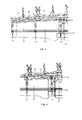
Figure 3 is an internal plan view of an area of a skin belonging to the torsion box of an aircraft wing according to a first embodiment of the present invention. -
Figure 4 is an internal plan view of an area of a skin belonging to the torsion box of an aircraft wing according to a second embodiment of the present invention. - The invention relates to a multi-rib torsion box structure of composite materials with longitudinal stiffeners, having preferably a T-shaped or a L-shaped cross-section. The composite material can be both carbon fiber and fiberglass with thermosetting or thermoplastic resin. The main field of application is aeronautical lifting surfaces structures, although they can also be applied to other structures with similar features.
- The main structure of an aircraft lifting surface such as a wing consists of a leading edge, a torsion box, a trailing edge, a root joint and a wing tip. A
multi-rib torsion box 1 such as the one depicted inFigures 1a and 1b is structurally based on a spanwise front spar 11 and a span wise rear spar 13 (understanding the terms front and rear in relation to the flight direction of the aircraft), a plurality of chordwise ribs lower skins wise stringers - The main functions of
ribs skins stringers - The primary function of the
skins said ribs stringers rear spar 13. -
Figure 2 shows a common case where thepanels ribs 27, 27', 27', the stringer 25' and thefront spar 11. In this case, thestringer 25 cannot be extended to decrease the size of thepanels front spar 11. - According to the invention those
panels - In a preferred embodiment, illustrated in
Figure 3 , saidstiffening elements 41 are isolated stiffening elements on eachpanel stringer 25 in theadjacent panel 35 and a point close to therib 27 at a suitable distance of thefront spar 11 to comply with the structural requirements. Saidstiffening elements 41 "break" theinitial panels smaller panels 31', 31"; 33', 33". Panels 31', 33' are now limited by thestiffening elements 41, the stringer 25' and theribs initial panels - In another preferred embodiment, said stiffening elements are installed on the
skins Figure 4 , thestiffening element 43 that, preferably, follows a lineal trace between the end of thestringer 25 in theadjacent panel 35 and a point close to the rib 27' at a suitable distance of thefront spar 11 to comply with the structural requirements, "breaks" theinitial panel 33 into thesmaller panels 33', 33". Panel 33' is now limited by thestiffening element 43, the stringer 25' and theribs 27', 27", having thus a smaller area than theinitial panel 33 allowing a thickness decrease and a weight reduction. On the other hand, thestiffening element 43 is joined to the rib 27' and to thestringer 25 ending in theadjacent panel 35, i.e. a joint arrangement that provides a better load continuity and distribution. - The
stiffening elements skins stiffening element 43 and the front spar 11 to allow the enlargement of the stiffening element foots needed in the joining areas withstringer 25 and rib 27'. - In a preferred embodiment, said
stiffening elements stringer 25, i.e. a T-shaped or a L-shaped transversal section. - Among others, the advantages of the present invention are the following:
- Reduction of the skin thickness and weight of the involved panels in an amount close to the 20%.
- Reduction of the buckling risk in the skin panels.
- Although the present invention has been fully described in connection with preferred embodiments, it is evident that modifications may be introduced within the scope thereof, not considering this as limited by these embodiments, but by the contents of the following claims.
Claims (9)
- A mult-rib box-shaped aeronautical structure comprising upper and lower skins (19, 21) stiffened by span wise stringers (25, 25', 25"), span wise front and rear spars (11, 13) and chord wise ribs (27, 27', 27"), characterized in that at least one panel (31, 33) of any of said skins (19, 21) is non delimited by said ribs (27, 27', 27") and said stringers (25, 25', 25") and comprise an stiffening element (41, 43) arranged as a panel breaker to avoid the need of increasing the panel thickness to withstand the buckling loads.
- A mult-rib box-shaped aeronautical structure according to claim 1, wherein the stiffening element (41) is an isolated stiffening element on said panel (31, 33).
- A mult-rib box-shaped aeronautical structure according to claim 1, wherein the stiffening element (43) is joined to another structural element.
- A mult-rib box-shaped aeronautical structure according to claim 3, wherein the stiffening element (43) is joined to a stringer (25).
- A mult-rib box-shaped aeronautical structure according to claim 4, wherein the stiffening element (43) is joined to a rib (27').
- A mult-rib box-shaped aeronautical structure according to any of claims 1-5, wherein the stiffening element (41, 43) follow a linear trace between the end of the closer stringer (25) and a final point in said panel (31, 33) at a suitable distance of the estructural element (11) that delimits said panel (31, 33) instead of an stringer.
- A mult-rib box-shaped aeronautical structure according to any of claims 1-6, wherein said stringers (25, 25', 25") and said stiffening elements (41, 43) have the same transversal shape.
- A mult-rib box-shaped aeronautical structure according to claim 7, wherein the transversal shape of said stringers (25, 25', 25") and said stiffening elements (41, 43) is a T-shape.
- A mult-rib box-shaped aeronautical structure according to claim 7, wherein the transversal shape of said stringers (25, 25', 25") and said stiffening elements (41, 43) is an L-shape.
Applications Claiming Priority (1)
| Application Number | Priority Date | Filing Date | Title |
|---|---|---|---|
| ES201031770A ES2402463B1 (en) | 2010-11-30 | 2010-11-30 | A COATING OF A SUSTAINING SURFACE OF AN AIRCRAFT. |
Publications (2)
| Publication Number | Publication Date |
|---|---|
| EP2457823A1 true EP2457823A1 (en) | 2012-05-30 |
| EP2457823B1 EP2457823B1 (en) | 2017-05-31 |
Family
ID=45218333
Family Applications (1)
| Application Number | Title | Priority Date | Filing Date |
|---|---|---|---|
| EP11191404.0A Active EP2457823B1 (en) | 2010-11-30 | 2011-11-30 | An aircraft lifting surface skin |
Country Status (4)
| Country | Link |
|---|---|
| US (1) | US20120132743A1 (en) |
| EP (1) | EP2457823B1 (en) |
| CA (1) | CA2759999A1 (en) |
| ES (1) | ES2402463B1 (en) |
Families Citing this family (1)
| Publication number | Priority date | Publication date | Assignee | Title |
|---|---|---|---|---|
| CN113044204A (en) * | 2021-04-29 | 2021-06-29 | 吉林大学 | Carbon fiber wing skeleton structure |
Citations (4)
| Publication number | Priority date | Publication date | Assignee | Title |
|---|---|---|---|---|
| EP0230682A2 (en) * | 1985-12-30 | 1987-08-05 | The Boeing Company | Aerodynamic structures of composite construction |
| WO2008007135A2 (en) * | 2006-07-13 | 2008-01-17 | Airbus Uk Limited | A wing cover panel assembly and wing cover panel for an aircraft wing and a method of forming thereof |
| EP1942052A1 (en) * | 2006-12-13 | 2008-07-09 | The Boeing Company | Rib support for wing panels |
| WO2008132498A1 (en) * | 2007-04-30 | 2008-11-06 | Airbus Uk Limited | Composite structure comprising a stringer with a pad embedded in the recess of a panel and method of transmitting forces |
Family Cites Families (4)
| Publication number | Priority date | Publication date | Assignee | Title |
|---|---|---|---|---|
| US7509740B2 (en) * | 2001-11-13 | 2009-03-31 | The Boeing Company | Method of manufacturing a wing |
| CN1089049C (en) * | 1996-03-22 | 2002-08-14 | 波音公司 | Aircraft wing spar, method of assembling aircraft wing spar and chord positioning tool |
| GB9713209D0 (en) * | 1997-06-20 | 1997-08-27 | British Aerospace | Friction welding metal components |
| US20030226935A1 (en) * | 2001-11-02 | 2003-12-11 | Garratt Matthew D. | Structural members having improved resistance to fatigue crack growth |
-
2010
- 2010-11-30 ES ES201031770A patent/ES2402463B1/en active Active
-
2011
- 2011-03-25 US US13/071,682 patent/US20120132743A1/en not_active Abandoned
- 2011-11-30 CA CA2759999A patent/CA2759999A1/en not_active Abandoned
- 2011-11-30 EP EP11191404.0A patent/EP2457823B1/en active Active
Patent Citations (4)
| Publication number | Priority date | Publication date | Assignee | Title |
|---|---|---|---|---|
| EP0230682A2 (en) * | 1985-12-30 | 1987-08-05 | The Boeing Company | Aerodynamic structures of composite construction |
| WO2008007135A2 (en) * | 2006-07-13 | 2008-01-17 | Airbus Uk Limited | A wing cover panel assembly and wing cover panel for an aircraft wing and a method of forming thereof |
| EP1942052A1 (en) * | 2006-12-13 | 2008-07-09 | The Boeing Company | Rib support for wing panels |
| WO2008132498A1 (en) * | 2007-04-30 | 2008-11-06 | Airbus Uk Limited | Composite structure comprising a stringer with a pad embedded in the recess of a panel and method of transmitting forces |
Also Published As
| Publication number | Publication date |
|---|---|
| EP2457823B1 (en) | 2017-05-31 |
| ES2402463B1 (en) | 2014-03-13 |
| US20120132743A1 (en) | 2012-05-31 |
| CA2759999A1 (en) | 2012-05-30 |
| ES2402463A1 (en) | 2013-05-03 |
Similar Documents
| Publication | Publication Date | Title |
|---|---|---|
| EP2848519B1 (en) | Upper joints between outboard wing boxes and wing center sections of aircraft wing assemblies | |
| CA2911447C (en) | Stiffened composite panels and method of their manufacture | |
| EP2824030B1 (en) | Apparatus and methods for joining composite structures of aircrafts | |
| US8276848B2 (en) | Rib structure for torsion boxes of a wing or horizontal stabiliser of an aircraft | |
| CN106335629B (en) | Fuselage spar structure with continuous integral fastened upper and lower chord sections | |
| EP2842867B1 (en) | Composite control surfaces for aircraft | |
| US20120234978A1 (en) | Load transfer devices at a stringer run-out | |
| EP2173615B1 (en) | Stiffened multispar torsion box | |
| US10518866B2 (en) | Control surface element for an airplane | |
| EP2589532A2 (en) | Aircraft fuselage made out with composite material and manufacturing processes | |
| US8899522B2 (en) | Aircraft fuselage with high strength frames | |
| KR20140120263A (en) | Continuously curved spar and method of manufacturing | |
| CN103429492B (en) | Torsion box skin stiffened with non-parallel stringers | |
| US10364017B2 (en) | Structural component | |
| EP2634093A1 (en) | Filler panels for aircraft fuel tank coverings | |
| ES2953735T3 (en) | Trailing edge for a composite multi-spar integrated lifting surface and manufacturing method of said trailing edge | |
| US20130270392A1 (en) | Interface arrangement for aircraft lifting surface | |
| EP2540618B1 (en) | Filler panel for bulkhead to skin joint in integral tanks | |
| US9010688B2 (en) | Structural joint having continuous skin with inside and outside stringers | |
| EP2886450A1 (en) | Aircraft control surface | |
| EP2457823B1 (en) | An aircraft lifting surface skin | |
| EP3015361A1 (en) | Central area arrangement for continuous horizontal tail plane torsion box | |
| Kaur et al. | Spars and stringers-function and designing | |
| US20120132754A1 (en) | Interface arrangement between two-components of an aircraft structure |
Legal Events
| Date | Code | Title | Description |
|---|---|---|---|
| PUAI | Public reference made under article 153(3) epc to a published international application that has entered the european phase |
Free format text: ORIGINAL CODE: 0009012 |
|
| AK | Designated contracting states |
Kind code of ref document: A1 Designated state(s): AL AT BE BG CH CY CZ DE DK EE ES FI FR GB GR HR HU IE IS IT LI LT LU LV MC MK MT NL NO PL PT RO RS SE SI SK SM TR |
|
| AX | Request for extension of the european patent |
Extension state: BA ME |
|
| 17P | Request for examination filed |
Effective date: 20121130 |
|
| 17Q | First examination report despatched |
Effective date: 20160407 |
|
| GRAP | Despatch of communication of intention to grant a patent |
Free format text: ORIGINAL CODE: EPIDOSNIGR1 |
|
| INTG | Intention to grant announced |
Effective date: 20161221 |
|
| GRAS | Grant fee paid |
Free format text: ORIGINAL CODE: EPIDOSNIGR3 |
|
| GRAA | (expected) grant |
Free format text: ORIGINAL CODE: 0009210 |
|
| AK | Designated contracting states |
Kind code of ref document: B1 Designated state(s): AL AT BE BG CH CY CZ DE DK EE ES FI FR GB GR HR HU IE IS IT LI LT LU LV MC MK MT NL NO PL PT RO RS SE SI SK SM TR |
|
| REG | Reference to a national code |
Ref country code: CH Ref legal event code: EP Ref country code: GB Ref legal event code: FG4D |
|
| REG | Reference to a national code |
Ref country code: AT Ref legal event code: REF Ref document number: 897194 Country of ref document: AT Kind code of ref document: T Effective date: 20170615 |
|
| REG | Reference to a national code |
Ref country code: IE Ref legal event code: FG4D |
|
| REG | Reference to a national code |
Ref country code: DE Ref legal event code: R096 Ref document number: 602011038298 Country of ref document: DE |
|
| REG | Reference to a national code |
Ref country code: NL Ref legal event code: MP Effective date: 20170531 |
|
| REG | Reference to a national code |
Ref country code: LT Ref legal event code: MG4D |
|
| REG | Reference to a national code |
Ref country code: AT Ref legal event code: MK05 Ref document number: 897194 Country of ref document: AT Kind code of ref document: T Effective date: 20170531 |
|
| PG25 | Lapsed in a contracting state [announced via postgrant information from national office to epo] |
Ref country code: HR Free format text: LAPSE BECAUSE OF FAILURE TO SUBMIT A TRANSLATION OF THE DESCRIPTION OR TO PAY THE FEE WITHIN THE PRESCRIBED TIME-LIMIT Effective date: 20170531 Ref country code: GR Free format text: LAPSE BECAUSE OF FAILURE TO SUBMIT A TRANSLATION OF THE DESCRIPTION OR TO PAY THE FEE WITHIN THE PRESCRIBED TIME-LIMIT Effective date: 20170901 Ref country code: LT Free format text: LAPSE BECAUSE OF FAILURE TO SUBMIT A TRANSLATION OF THE DESCRIPTION OR TO PAY THE FEE WITHIN THE PRESCRIBED TIME-LIMIT Effective date: 20170531 Ref country code: FI Free format text: LAPSE BECAUSE OF FAILURE TO SUBMIT A TRANSLATION OF THE DESCRIPTION OR TO PAY THE FEE WITHIN THE PRESCRIBED TIME-LIMIT Effective date: 20170531 Ref country code: AT Free format text: LAPSE BECAUSE OF FAILURE TO SUBMIT A TRANSLATION OF THE DESCRIPTION OR TO PAY THE FEE WITHIN THE PRESCRIBED TIME-LIMIT Effective date: 20170531 Ref country code: NO Free format text: LAPSE BECAUSE OF FAILURE TO SUBMIT A TRANSLATION OF THE DESCRIPTION OR TO PAY THE FEE WITHIN THE PRESCRIBED TIME-LIMIT Effective date: 20170831 Ref country code: ES Free format text: LAPSE BECAUSE OF FAILURE TO SUBMIT A TRANSLATION OF THE DESCRIPTION OR TO PAY THE FEE WITHIN THE PRESCRIBED TIME-LIMIT Effective date: 20170531 |
|
| REG | Reference to a national code |
Ref country code: FR Ref legal event code: PLFP Year of fee payment: 7 |
|
| PG25 | Lapsed in a contracting state [announced via postgrant information from national office to epo] |
Ref country code: RS Free format text: LAPSE BECAUSE OF FAILURE TO SUBMIT A TRANSLATION OF THE DESCRIPTION OR TO PAY THE FEE WITHIN THE PRESCRIBED TIME-LIMIT Effective date: 20170531 Ref country code: LV Free format text: LAPSE BECAUSE OF FAILURE TO SUBMIT A TRANSLATION OF THE DESCRIPTION OR TO PAY THE FEE WITHIN THE PRESCRIBED TIME-LIMIT Effective date: 20170531 Ref country code: NL Free format text: LAPSE BECAUSE OF FAILURE TO SUBMIT A TRANSLATION OF THE DESCRIPTION OR TO PAY THE FEE WITHIN THE PRESCRIBED TIME-LIMIT Effective date: 20170531 Ref country code: SE Free format text: LAPSE BECAUSE OF FAILURE TO SUBMIT A TRANSLATION OF THE DESCRIPTION OR TO PAY THE FEE WITHIN THE PRESCRIBED TIME-LIMIT Effective date: 20170531 Ref country code: BG Free format text: LAPSE BECAUSE OF FAILURE TO SUBMIT A TRANSLATION OF THE DESCRIPTION OR TO PAY THE FEE WITHIN THE PRESCRIBED TIME-LIMIT Effective date: 20170831 Ref country code: IS Free format text: LAPSE BECAUSE OF FAILURE TO SUBMIT A TRANSLATION OF THE DESCRIPTION OR TO PAY THE FEE WITHIN THE PRESCRIBED TIME-LIMIT Effective date: 20170930 |
|
| PG25 | Lapsed in a contracting state [announced via postgrant information from national office to epo] |
Ref country code: SK Free format text: LAPSE BECAUSE OF FAILURE TO SUBMIT A TRANSLATION OF THE DESCRIPTION OR TO PAY THE FEE WITHIN THE PRESCRIBED TIME-LIMIT Effective date: 20170531 Ref country code: DK Free format text: LAPSE BECAUSE OF FAILURE TO SUBMIT A TRANSLATION OF THE DESCRIPTION OR TO PAY THE FEE WITHIN THE PRESCRIBED TIME-LIMIT Effective date: 20170531 Ref country code: RO Free format text: LAPSE BECAUSE OF FAILURE TO SUBMIT A TRANSLATION OF THE DESCRIPTION OR TO PAY THE FEE WITHIN THE PRESCRIBED TIME-LIMIT Effective date: 20170531 Ref country code: EE Free format text: LAPSE BECAUSE OF FAILURE TO SUBMIT A TRANSLATION OF THE DESCRIPTION OR TO PAY THE FEE WITHIN THE PRESCRIBED TIME-LIMIT Effective date: 20170531 Ref country code: CZ Free format text: LAPSE BECAUSE OF FAILURE TO SUBMIT A TRANSLATION OF THE DESCRIPTION OR TO PAY THE FEE WITHIN THE PRESCRIBED TIME-LIMIT Effective date: 20170531 |
|
| PG25 | Lapsed in a contracting state [announced via postgrant information from national office to epo] |
Ref country code: IT Free format text: LAPSE BECAUSE OF FAILURE TO SUBMIT A TRANSLATION OF THE DESCRIPTION OR TO PAY THE FEE WITHIN THE PRESCRIBED TIME-LIMIT Effective date: 20170531 Ref country code: PL Free format text: LAPSE BECAUSE OF FAILURE TO SUBMIT A TRANSLATION OF THE DESCRIPTION OR TO PAY THE FEE WITHIN THE PRESCRIBED TIME-LIMIT Effective date: 20170531 Ref country code: SM Free format text: LAPSE BECAUSE OF FAILURE TO SUBMIT A TRANSLATION OF THE DESCRIPTION OR TO PAY THE FEE WITHIN THE PRESCRIBED TIME-LIMIT Effective date: 20170531 |
|
| REG | Reference to a national code |
Ref country code: DE Ref legal event code: R097 Ref document number: 602011038298 Country of ref document: DE |
|
| PLBE | No opposition filed within time limit |
Free format text: ORIGINAL CODE: 0009261 |
|
| STAA | Information on the status of an ep patent application or granted ep patent |
Free format text: STATUS: NO OPPOSITION FILED WITHIN TIME LIMIT |
|
| 26N | No opposition filed |
Effective date: 20180301 |
|
| PG25 | Lapsed in a contracting state [announced via postgrant information from national office to epo] |
Ref country code: SI Free format text: LAPSE BECAUSE OF FAILURE TO SUBMIT A TRANSLATION OF THE DESCRIPTION OR TO PAY THE FEE WITHIN THE PRESCRIBED TIME-LIMIT Effective date: 20170531 |
|
| PG25 | Lapsed in a contracting state [announced via postgrant information from national office to epo] |
Ref country code: MC Free format text: LAPSE BECAUSE OF FAILURE TO SUBMIT A TRANSLATION OF THE DESCRIPTION OR TO PAY THE FEE WITHIN THE PRESCRIBED TIME-LIMIT Effective date: 20170531 |
|
| PG25 | Lapsed in a contracting state [announced via postgrant information from national office to epo] |
Ref country code: CH Free format text: LAPSE BECAUSE OF NON-PAYMENT OF DUE FEES Effective date: 20171130 Ref country code: LI Free format text: LAPSE BECAUSE OF NON-PAYMENT OF DUE FEES Effective date: 20171130 |
|
| PG25 | Lapsed in a contracting state [announced via postgrant information from national office to epo] |
Ref country code: LU Free format text: LAPSE BECAUSE OF NON-PAYMENT OF DUE FEES Effective date: 20171130 |
|
| REG | Reference to a national code |
Ref country code: BE Ref legal event code: MM Effective date: 20171130 |
|
| REG | Reference to a national code |
Ref country code: IE Ref legal event code: MM4A |
|
| PG25 | Lapsed in a contracting state [announced via postgrant information from national office to epo] |
Ref country code: MT Free format text: LAPSE BECAUSE OF NON-PAYMENT OF DUE FEES Effective date: 20171130 |
|
| PG25 | Lapsed in a contracting state [announced via postgrant information from national office to epo] |
Ref country code: IE Free format text: LAPSE BECAUSE OF NON-PAYMENT OF DUE FEES Effective date: 20171130 |
|
| PG25 | Lapsed in a contracting state [announced via postgrant information from national office to epo] |
Ref country code: BE Free format text: LAPSE BECAUSE OF NON-PAYMENT OF DUE FEES Effective date: 20171130 |
|
| PG25 | Lapsed in a contracting state [announced via postgrant information from national office to epo] |
Ref country code: HU Free format text: LAPSE BECAUSE OF FAILURE TO SUBMIT A TRANSLATION OF THE DESCRIPTION OR TO PAY THE FEE WITHIN THE PRESCRIBED TIME-LIMIT; INVALID AB INITIO Effective date: 20111130 |
|
| PG25 | Lapsed in a contracting state [announced via postgrant information from national office to epo] |
Ref country code: CY Free format text: LAPSE BECAUSE OF NON-PAYMENT OF DUE FEES Effective date: 20170531 |
|
| PG25 | Lapsed in a contracting state [announced via postgrant information from national office to epo] |
Ref country code: MK Free format text: LAPSE BECAUSE OF FAILURE TO SUBMIT A TRANSLATION OF THE DESCRIPTION OR TO PAY THE FEE WITHIN THE PRESCRIBED TIME-LIMIT Effective date: 20170531 |
|
| PG25 | Lapsed in a contracting state [announced via postgrant information from national office to epo] |
Ref country code: TR Free format text: LAPSE BECAUSE OF FAILURE TO SUBMIT A TRANSLATION OF THE DESCRIPTION OR TO PAY THE FEE WITHIN THE PRESCRIBED TIME-LIMIT Effective date: 20170531 |
|
| PG25 | Lapsed in a contracting state [announced via postgrant information from national office to epo] |
Ref country code: PT Free format text: LAPSE BECAUSE OF FAILURE TO SUBMIT A TRANSLATION OF THE DESCRIPTION OR TO PAY THE FEE WITHIN THE PRESCRIBED TIME-LIMIT Effective date: 20170531 |
|
| PG25 | Lapsed in a contracting state [announced via postgrant information from national office to epo] |
Ref country code: AL Free format text: LAPSE BECAUSE OF FAILURE TO SUBMIT A TRANSLATION OF THE DESCRIPTION OR TO PAY THE FEE WITHIN THE PRESCRIBED TIME-LIMIT Effective date: 20170531 |
|
| PGFP | Annual fee paid to national office [announced via postgrant information from national office to epo] |
Ref country code: DE Payment date: 20251119 Year of fee payment: 15 |
|
| PGFP | Annual fee paid to national office [announced via postgrant information from national office to epo] |
Ref country code: GB Payment date: 20251121 Year of fee payment: 15 |
|
| PGFP | Annual fee paid to national office [announced via postgrant information from national office to epo] |
Ref country code: FR Payment date: 20251125 Year of fee payment: 15 |