EP2457524A1 - Access assembly including one or more foldable caps - Google Patents
Access assembly including one or more foldable caps Download PDFInfo
- Publication number
- EP2457524A1 EP2457524A1 EP20110250791 EP11250791A EP2457524A1 EP 2457524 A1 EP2457524 A1 EP 2457524A1 EP 20110250791 EP20110250791 EP 20110250791 EP 11250791 A EP11250791 A EP 11250791A EP 2457524 A1 EP2457524 A1 EP 2457524A1
- Authority
- EP
- European Patent Office
- Prior art keywords
- lumens
- tubular member
- access assembly
- foldable
- access
- Prior art date
- Legal status (The legal status is an assumption and is not a legal conclusion. Google has not performed a legal analysis and makes no representation as to the accuracy of the status listed.)
- Granted
Links
- 238000000034 method Methods 0.000 claims description 22
- 238000003780 insertion Methods 0.000 claims description 7
- 230000037431 insertion Effects 0.000 claims description 7
- 238000007789 sealing Methods 0.000 claims description 7
- 239000000779 smoke Substances 0.000 claims description 7
- 239000011521 glass Substances 0.000 claims description 3
- 238000001356 surgical procedure Methods 0.000 description 22
- 230000007246 mechanism Effects 0.000 description 13
- 230000000712 assembly Effects 0.000 description 9
- 238000000429 assembly Methods 0.000 description 9
- 239000012530 fluid Substances 0.000 description 4
- 239000000463 material Substances 0.000 description 4
- 241001631457 Cannula Species 0.000 description 3
- 210000000056 organ Anatomy 0.000 description 3
- 229920002725 thermoplastic elastomer Polymers 0.000 description 3
- 230000009286 beneficial effect Effects 0.000 description 2
- 230000008901 benefit Effects 0.000 description 2
- 229920001971 elastomer Polymers 0.000 description 2
- 239000006260 foam Substances 0.000 description 2
- 229920001296 polysiloxane Polymers 0.000 description 2
- 239000005060 rubber Substances 0.000 description 2
- 210000000683 abdominal cavity Anatomy 0.000 description 1
- 210000003815 abdominal wall Anatomy 0.000 description 1
- 210000000436 anus Anatomy 0.000 description 1
- 230000006835 compression Effects 0.000 description 1
- 238000007906 compression Methods 0.000 description 1
- 239000000499 gel Substances 0.000 description 1
- 238000002357 laparoscopic surgery Methods 0.000 description 1
- 238000012986 modification Methods 0.000 description 1
- 230000004048 modification Effects 0.000 description 1
- 210000000214 mouth Anatomy 0.000 description 1
- 239000000523 sample Substances 0.000 description 1
- 210000001215 vagina Anatomy 0.000 description 1
Images



Classifications
-
- A—HUMAN NECESSITIES
- A61—MEDICAL OR VETERINARY SCIENCE; HYGIENE
- A61B—DIAGNOSIS; SURGERY; IDENTIFICATION
- A61B17/00—Surgical instruments, devices or methods
- A61B17/34—Trocars; Puncturing needles
- A61B17/3417—Details of tips or shafts, e.g. grooves, expandable, bendable; Multiple coaxial sliding cannulas, e.g. for dilating
- A61B17/3421—Cannulas
- A61B17/3423—Access ports, e.g. toroid shape introducers for instruments or hands
-
- A—HUMAN NECESSITIES
- A61—MEDICAL OR VETERINARY SCIENCE; HYGIENE
- A61B—DIAGNOSIS; SURGERY; IDENTIFICATION
- A61B17/00—Surgical instruments, devices or methods
- A61B17/34—Trocars; Puncturing needles
- A61B17/3417—Details of tips or shafts, e.g. grooves, expandable, bendable; Multiple coaxial sliding cannulas, e.g. for dilating
- A61B17/3421—Cannulas
- A61B2017/3443—Cannulas with means for adjusting the length of a cannula
-
- A—HUMAN NECESSITIES
- A61—MEDICAL OR VETERINARY SCIENCE; HYGIENE
- A61B—DIAGNOSIS; SURGERY; IDENTIFICATION
- A61B17/00—Surgical instruments, devices or methods
- A61B17/34—Trocars; Puncturing needles
- A61B17/3462—Trocars; Puncturing needles with means for changing the diameter or the orientation of the entrance port of the cannula, e.g. for use with different-sized instruments, reduction ports, adapter seals
- A61B2017/3466—Trocars; Puncturing needles with means for changing the diameter or the orientation of the entrance port of the cannula, e.g. for use with different-sized instruments, reduction ports, adapter seals for simultaneous sealing of multiple instruments
Definitions
- the present disclosure relates to an apparatus and method for accessing a body cavity. More particularly, the present disclosure relates to an access assembly including one or more foldable caps.
- Access assemblies configured for reception through an incision into an abdominal cavity are known, as are methods of inserting the access assemblies therethrough.
- Traditional access assemblies include a rigid cannula that is received through the tissue of the body wall into the body cavity. Endoscopic, laparoscopic and other suitable instruments may then be directed through a housing on the proximal end of the cannula to access the body cavity in a sealing manner in a variety of electrosurgical procedures.
- compressible assemblies configured for accessing a body cavity and permitting reception of electrosurgical instruments therethrough in a sealing manner are also known.
- Such compressible assemblies are composed of silicone, thermoplastic elastomers (TPE), rubber, foam, gel and other compressible materials and are configured to be compressed to facilitate insertion into an incision.
- TPE thermoplastic elastomers
- Such assemblies are deformed by a surgeon using his/her fingers or with the assistance of a grasping device, e.g., forceps. Compression of the assembly reduces the profile of the assembly, thereby facilitating reception of the assembly into the incision.
- the compressed assembly Upon release of the compressive force, the compressed assembly returns to an uncompressed configuration. In the uncompressed configuration, the access assembly seals the incision into the body cavity.
- the assembly may have one or more access ports for receiving the electrosurgical instruments therethrough and applying electrosurgical energy to tissue.
- an access assembly configured to be inserted through tissue, such that surgical instruments may be easily inserted therethrough. It would also be beneficial to have an access assembly that is reconfigurable to accommodate a different number of surgical instruments.
- the access assembly includes a tubular member having a proximal end and a distal end, the proximal end in mechanical cooperation with a foldable cap member having a first set of lumens extending the length of the tubular member.
- the access assembly also includes a first ring secured at the proximal end of the tubular member and a second ring secured at the distal end of the tubular member.
- the foldable cap member is configured to fold in at least one direction to expose a second set of lumens extending the length of the tubular member.
- the first ring is configured to be received external of the tissue, whereas the second ring is configured to be received within a body cavity.
- the tubular member is configured to be tapered in a first position to facilitate insertion through the tissue and is configured to define a substantially hour-glass shape in a second position.
- the foldable cap member includes two equally sized portions pivotable attached to each other.
- the first portion is configured to snap fit over the second portion to expose the second set of lumens.
- the foldable cap member includes a plurality of segments or portions pivotably attached to each other.
- the first set of lumens are configured to be a first size and the second set of lumens are configured to be a second size, the first and second sizes being different from each other.
- the second sets of lumens are configured to be slit sealing members.
- the method includes the steps of providing a tubular member having a proximal end and a distal end, the proximal end in mechanical cooperation with a foldable cap member having a first set of lumens extending the length of the tubular member; providing a first ring secured at the proximal end of the tubular member; and providing a second ring secured at the distal end of the tubular member; wherein the foldable cap member is configured to fold in at least one direction to expose a second set of lumens extending the length of the tubular member.
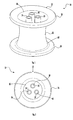
- FIG. 1 is a perspective view of an access assembly having a plurality of channels
- FIG. 2 is a top view of the access assembly of FIG. 1 illustrating the plurality of channels
- FIG. 3 is a perspective view of the access assembly of FIG. 1 inserted through tissue during a surgical procedure
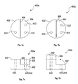
- FIG. 4A is a top view of a cap assembly, according to an aspect of the present disclosure, where two channels are visible or accessible by a surgeon;
- FIG. 4B is a top view of the cap assembly of FIG. 4A , according to an aspect of the present disclosure, where the foldable cap has been folded such that four channels are visible or accessible by the surgeon;
- FIG. 5A is a side view of the foldable cap of FIG. 4A , according to an aspect of the present disclosure, depicting the foldable cap in a first configuration
- FIG. 5B is a side view of the foldable cap of FIG. 4B , according to an aspect of the present disclosure, depicting the foldable cap in a second configuration;
- FIG. 6A is a top view of a cap assembly, according to an aspect of the present disclosure, where two channels are visible or accessible by the surgeon;
- FIG. 6B is a top view of the cap assembly of FIG. 6A , according to an aspect of the present disclosure, where the foldable cap has been folded such that three channels are visible or accessible by the surgeon;
- FIG. 7A is a side view of the foldable cap of FIG. 6A , according to an aspect of the present disclosure, depicting the foldable cap in a first configuration
- FIG. 7B is a side view of the foldable cap of FIG. 6B , according to an aspect of the present disclosure, depicting the foldable cap in a second configuration;
- FIG. 8A is a top view of a cap assembly, according to an aspect of the present disclosure, where four channels are visible or accessible by the surgeon;
- FIG. 8B is a top view of the cap assembly of FIG. 8A , according to an aspect of the present disclosure, where the foldable cap has been folded such that six channels are visible or accessible by the surgeon;
- FIG. 9A is a side view of the foldable cap of FIG. 8A , according to an aspect of the present disclosure, depicting the foldable cap in a first configuration
- FIG. 9B is a side view of the foldable cap of FIG. 8B , according to an aspect of the present disclosure, depicting the foldable cap in a second configuration.
- the access ports of the present disclosure either alone or in combination with a cannula assembly, provide a substantially fluid-tight seal between a body cavity of a patient and the outside atmosphere.
- the access ports, or seal assemblies, of the present disclosure are configured to receive surgical instruments of varying diameter.
- Various surgical procedures contemplated include laparoscopic and arthroscopic surgical procedures.
- the access ports of the present disclosure contemplate the introduction of various types of instrumentation adapted for insertion through a trocar and/or cannula assembly while maintaining a substantially fluid-tight interface about the instrument to help preserve the atmospheric integrity of a surgical procedure from gas and/or fluid leakage.
- instrumentation include, but are not limited to, clip appliers, graspers, dissectors, retractors, staplers, laser probes, photographic devices, endoscopes and laparoscopes, tubes, and the like.
- instrumentation include, but are not limited to, clip appliers, graspers, dissectors, retractors, staplers, laser probes, photographic devices, endoscopes and laparoscopes, tubes, and the like.
- instruments will collectively be referred to as "instruments” or "instrumentation.”
- distal refers to that portion of the tool, or component thereof which is further from the user while the term “proximal” refers to that portion of the tool or component thereof which is closer to the user.
- proximal refers to that portion of the tool or component thereof which is closer to the user.
- Flexible port seal 10 for use in single incision surgery.
- Flexible port seal 10 is flexible or compressible to allow it to be inserted through a single incision in the body of a patient such that after insertion it will expand and seal within the incision. Additionally, the flexible nature of flexible port seal 10 allows surgical instruments inserted therethrough to be manipulated relative to their respective axes and thus allows a relatively high degree of movement of the surgical instruments to orient them appropriate to the tissue being operated upon.
- Flexible port seal 10 generally includes an outer tissue seal 12 having one or more throughports 14, 16, and 18 extending therethrough. Throughports 14, 16, and 18 are provided to receive various surgical cannulas and/or instruments therethrough. The close proximity of throughports 14, 16, and 18 allows for unrestricted, independent movement of the surgical instruments inserted therethrough.
- Outer tissue seal 12 is formed from a flexible material which, as noted hereinabove, allows flexible port seal 10 to be compressed and inserted through an incision in the body of a patient as well as allowing for independent movement of throughports 14, 16, and 18.
- Outer tissue seal 12 may be formed of various materials such as, for example, silicone, thermoplastic elastomers, rubber, foam, gel, etc. Where desired, throughports 14, 16, and 18 may also be formed from various flexible materials and may be integrally formed therewith.
- outer tissue seal 12 includes a central portion 22 having an upper rim 24 located at a proximal end 26 of central portion 22.
- a lower rim 28 is located on a distal end 30 of central portion 22.
- Upper rim 24 and lower rim 28 aid in preventing movement of flexible port seal 10 longitudinally through the incision in the patient.
- throughports 14, 16, and 18 may have different lengths or diameters as compared to each other, and may respectively extend in either direction for any distance relative to the central portion 22.
- any one or more of the throughports 14, 16, 18 may extend beyond the distal end 30 of central portion 22 or may extend to less than the proximal end 26 of the central portion 22.
- These differences in lengths may allow the flexible port seal 10 to be more easily compressed prior to insertion within an incision.
- these differences in lengths may allow the flexible port seal 10 to accommodate different types of surgical instrumentation, different surgical procedures, etc.
- a central support plate or disk 20 may be provided to support throughports 14, 16, and 18 within outer tissue seal 12.
- surgical instrumentation such as, for example, conventional cannulas 82, 84, and 86 may be inserted through throughports 14, 16, and 18 (see FIG. 1 ).
- Cannulas 82, 84, and 86 include respective housings 88, 90, and 92.
- Housings 88, 90, and 92 include respective access tubes 94, 96, and 98 extending distally from housings 88, 90, and 92.
- housing 92 of cannula 86 may be provided with an insufflation port 100 which is connected to a source of insufflation fluid to insufflate the area and within the body beneath tissue T.
- the flexible port seal 10 may have additional tubes, ports or connections (not shown) that separately operate to connect to and provide insufflation fluid or to provide smoke evacuation if desired. Once the body has been properly insufflated, an organ may be operated upon to excise it from the surrounding tissue.
- access tube 98 is inserted through throughport 18.
- throughport 18 is provided with an instrument seal, such as, for example an hourglass seal, which forms a fluid tight seal around access tube 98 inserted therethrough.
- the cannula 86 may be selected so as to have a tight fit within the throughbore of the throughport 18, thereby eliminating the need to have an instrument seal within the throughbore of the throughport 18.
- the cannula 86 may include any type of fixation element, e.g., external threads, ribs, locking mechanisms, etc., that help maintain the cannula in position and help maintain the seal between the surface of the cannula 86 and the inner surface of the throughport 18.
- the support plate or disk 20 described above with reference to FIG. 2
- a cap assembly for positioning one or more access channels within an access assembly.
- the cap assembly may allow for a surgeon to selectively adjust the number of channels to be accessed, while performing a surgical procedure.
- FIG. 4A a top view of a cap assembly, according to an aspect of the present disclosure, where two channels are visible or accessible to a surgeon is presented.
- FIG. 4B a top view of the cap assembly of FIG. 4A , according to an aspect of the present disclosure, where the foldable cap has been folded such that four channels are visible or accessible to a surgeon is presented.
- FIG. 5A a side view of the foldable cap of FIG. 4A , according to an aspect of the present disclosure, depicting the foldable cap in a first configuration is presented.
- FIG. 5B a side view of the foldable cap of FIG. 4B , according to an aspect of the present disclosure, depicting the foldable cap in a second configuration is presented.
- the top view 400a of cap assembly 500a includes a first portion 402 and a second portion 404.
- the first portion 402 is connected to the second portion 404 via a connecting mechanism 406.
- the connection mechanism 406 may be at least a hinge, bracket or joint (e.g., pivotably attachable mechanism).
- the first portion 402 allows a surgeon access to a first channel 410.
- the second portion 404 includes three channels. However, in a first configuration, as shown in FIG. 4A , only one of the three channels is visible or accessible by the surgeon. For example, channel 414 is visible or accessible, whereas channels 412 and 416 are not yet visible and not accessible (shown with phantom lines).
- the surgeon has access to 2 channels (e.g., 410 and 414) to work with when performing a surgical procedure. If the surgeon requires more channels to perform the surgical procedure, the surgeon may flip the second portion 404 onto the first portion 402 in order to expose further channels, as described with reference to FIGS. 4B and 5B .
- FIG. 4B in a second configuration, the surgeon flips a cap segment 425 (see FIGS. 5A, 5B ) to expose the other two channels (e.g., channels 412' and 416').
- the top view 400b of cap assembly 500b of FIGS. 4B, 5B depict a first portion 402' and a second portion 404'.
- the first portion 402' is connected to the second portion 404' via a connecting mechanism 406.
- the first portion 402' is the bottom side of the second portion 404 of FIG. 4A .
- the second portion 404' is the exposed layer or surface of the cap assembly 400a (see FIGS. 5A and 5B for flipping action), after cap segment 425 has been flipped.
- the surgeon flips the second portion 404 onto the first portion 402, the first portion 402' still allows access to the surgical site via the first channel 410.
- the second portion 404' now allows access to all three channels (e.g., 412', 414, 416'). Therefore, with a flip of a cap segment 425, the surgeon may increase the available channels for a surgical procedure from 2 channels to 4 channels. This provides the surgeon with more flexibility before and during surgical procedures.
- the cap assembly 500a may be positioned within an access assembly, as described above with reference to FIGS. 1-3 . However, it is contemplated that the cap assembly 500a may be an attachable component or unit that is removable attachable to existing access assemblies. Therefore, the foldable cap member is configured to fold in at least one direction to expose a second set of lumens extending the length of the tubular member of the access assembly.
- FIG. 6A a top view of a cap assembly, according to an aspect of the present disclosure, where two channels are visible or accessible to the surgeon is presented.
- FIG. 6B a top view of the cap assembly of FIG. 6A , according to an aspect of the present disclosure, where the foldable cap has been folded such that three channels are visible or accessible to the surgeon is presented.
- FIG. 7A a side view of the foldable cap of FIG. 6B , according to an aspect of the present disclosure, depicting the foldable cap in a second configuration is presented.
- FIG. 7B a side view of the foldable cap of FIG. 6B , according to an aspect of the present disclosure, depicting the foldable cap in a second configuration is presented.
- the top view 600a of cap assembly 700a includes a first portion 602 and a second portion 604.
- the first portion 602 is connected to the second portion 604 via a connecting mechanism 606.
- the connection mechanism 606 may be at least a hinge, bracket or joint (e.g., pivotably attachable mechanism).
- the first portion 602 allows a surgeon access to a first channel 610.
- the second portion 604 includes two channels. However, in a first configuration, as shown in FIG. 6A , only one of the two channels is visible or accessible by the surgeon. For example, channel 616 is visible or accessible, whereas channel 612 is not yet visible and not accessible (shown with phantom lines).
- the surgeon has access to 2 channels (e.g., 610 and 616) to work with when performing a surgical procedure. If the surgeon requires more channels to perform the surgical procedure, the surgeon may flip the second portion 604 onto the first portion 602 in order to expose further channels, as described with reference to FIGS. 6B and 7B .
- 2 channels e.g., 610 and 616
- FIG. 7B in a second configuration, the surgeon flips a cap segment 625 (see FIGS. 6A, 6B ) to expose another channel (e.g., channel 612').
- the first portion 602' is connected to the second portion 604' via a connecting mechanism 606.
- the first portion 602' is the bottom side of the second portion 604 of FIG. 6A .
- the second portion 604' is the exposed layer or surface of the cap assembly 600a (see FIGS. 7A and 7B for flipping action), after cap segment 625 has been flipped.
- the surgeon flips the second portion 604 onto the first portion 602, the first portion 602' still allows access to the surgical site via the first channel 610.
- the second portion 604' now allows access to both channels (e.g., 612', 616). Therefore, with a flip of a cap segment 625, the surgeon may increase the available channels for a surgical procedure from 2 channels to 3 channels. This provides the surgeon with more flexibility before and during surgical procedures.
- the cap assembly 700a may be positioned within an access assembly, as described above with reference to FIGS. 1-3 . However, it is contemplated that the cap assembly 700a may be an attachable component or unit that is removably attachable to existing access assemblies. Therefore, the foldable cap member is configured to fold in at least one direction to expose a second set of lumens extending the length of the tubular member of the access assembly.
- FIGS. 4A-7B are merely exemplary.
- the foldable cap member included two equally sized portions pivotally attached to each other.
- one skilled in the art may contemplate using a plurality of different cap assembly mechanisms in a number of different configurations to aid access to a number of different channels or lumens.
- any number of initial channels may be initially exposed and that any number of subsequent channels may be subsequently revealed.
- the cap assembly is split into more than 2 portions (as described with reference to FIGS. 8A-9B below).
- first portion may snap fit onto the second portion. It is contemplated that the first portion is a different size than the second portion.
- the first set of lumens (initially exposed) may be configured to be a first size and the second set of lumens (subsequently revealed) may be configured to be a second size, the first and second sizes being different from each other.
- the second set of lumens may be configured to act as smoke vents for enabling smoke evacuation from a surgical site or may be configured to receive additional surgical instruments therethrough.
- FIG. 8A a top view of a cap assembly, according to an aspect of the present disclosure, where four channels are visible or accessible to the surgeon is presented.
- FIG. 8B a top view of the cap assembly of FIG. 8A , according to an aspect of the present disclosure, where the foldable cap has been folded such that six channels are visible or accessible to the surgeon is presented.
- FIG. 9A a side view of the foldable cap of FIG. 8A , according to an aspect of the present disclosure, depicting the foldable cap in a first configuration is presented.
- FIG. 9B a side view of the foldable cap of FIG. 8B , according to an aspect of the present disclosure, depicting the foldable cap in a second configuration is presented.
- the top view 800a of cap assembly 900a includes a first portion 802, a second portion 804, a third portion 806, and a fourth portion 808.
- the first, second, third, and fourth portions 802, 804, 806, 808 are connected to each other via connecting mechanisms 810, 812.
- the connection mechanisms 810, 812 may be at least a hinge, bracket or joint (or pivotally attached members).
- the first portion 802 allows the surgeon access to a first channel 820
- the second portion 804 allows access to a second channel 824
- the third portion 806 allows access to a third channel 828
- the fourth portion 808 allows access to a fourth channel 830.
- four channels are visible or accessible by the surgeon.
- channels 820, 824, 828, 830 are visible or accessible, whereas channels 822, 826 are not yet visible and not accessible (shown with phantom lines).
- the surgeon has access to 4 channels (e.g., 820, 824, 828, 830) to work with when performing a surgical procedure.
- the channels 820, 824, 828, 830 are located at predetermined areas on portions 802, 804, 806, 808.
- surgeon may flip the second portion 804 onto the first portion 802 and may also flip the third portion 806 onto the fourth portion 808 in order to expose additional channels that may be more convenient to access other organs during surgery, as described with reference to FIGS. 8B and 9B .
- the surgeon flips cap segments 825 (see FIGS. 9A, 9B ) to expose the other two channels (e.g., channels 822' and 826').
- the surgeon flips the second portion 804 onto the first portion 802, and the third portion 806 onto the fourth portion 808, the first portion 802 still allows access to the surgical site via the first channel 820.
- the first portion 802 also allows access to a new channel (e.g., 822'). Therefore, with a flip of a cap segment 825, the surgeon may increase the available channels for a surgical procedure from 1 channel to 2 channels in the first portion 802.
- the third portion 806 still allows access to the surgical site via the third channel 828.
- the third portion 806 also allows access to a new channel (e.g., 826'). Therefore, with a flip of a cap segment 825, the surgeon may increase the available channels for a surgical procedure from 1 channel to 2 channels in the third portion 806. As a result, the surgeon may flip two cap segments 825 in order to increase the number of channels from 4 to 6.
- cap assembly may be used in a number of different configurations to aid access to a number of different channels or lumens.
- any number of initial channels may be initially exposed and that any number of subsequent channels may be subsequently revealed.
- the cap assembly is split into a plurality of portions having a plurality of cap segments to be flipped.
Landscapes
- Health & Medical Sciences (AREA)
- Surgery (AREA)
- Life Sciences & Earth Sciences (AREA)
- Medical Informatics (AREA)
- Nuclear Medicine, Radiotherapy & Molecular Imaging (AREA)
- Engineering & Computer Science (AREA)
- Biomedical Technology (AREA)
- Heart & Thoracic Surgery (AREA)
- Pathology (AREA)
- Molecular Biology (AREA)
- Animal Behavior & Ethology (AREA)
- General Health & Medical Sciences (AREA)
- Public Health (AREA)
- Veterinary Medicine (AREA)
- Surgical Instruments (AREA)
- Endoscopes (AREA)
Abstract
Description
- The present application claims the benefit of and priority to
U.S. Provisional Patent Application Serial No. 61/416,769 filed on November 24, 2010 - The present disclosure relates to an apparatus and method for accessing a body cavity. More particularly, the present disclosure relates to an access assembly including one or more foldable caps.
- Access assemblies configured for reception through an incision into an abdominal cavity are known, as are methods of inserting the access assemblies therethrough. Traditional access assemblies include a rigid cannula that is received through the tissue of the body wall into the body cavity. Endoscopic, laparoscopic and other suitable instruments may then be directed through a housing on the proximal end of the cannula to access the body cavity in a sealing manner in a variety of electrosurgical procedures.
- Moreover, compressible assemblies configured for accessing a body cavity and permitting reception of electrosurgical instruments therethrough in a sealing manner are also known. Such compressible assemblies are composed of silicone, thermoplastic elastomers (TPE), rubber, foam, gel and other compressible materials and are configured to be compressed to facilitate insertion into an incision. Typically, such assemblies are deformed by a surgeon using his/her fingers or with the assistance of a grasping device, e.g., forceps. Compression of the assembly reduces the profile of the assembly, thereby facilitating reception of the assembly into the incision. Upon release of the compressive force, the compressed assembly returns to an uncompressed configuration. In the uncompressed configuration, the access assembly seals the incision into the body cavity. The assembly may have one or more access ports for receiving the electrosurgical instruments therethrough and applying electrosurgical energy to tissue.
- Therefore, it would be beneficial to have an access assembly configured to be inserted through tissue, such that surgical instruments may be easily inserted therethrough. It would also be beneficial to have an access assembly that is reconfigurable to accommodate a different number of surgical instruments.
- Accordingly, an improved access assembly is provided. The access assembly includes a tubular member having a proximal end and a distal end, the proximal end in mechanical cooperation with a foldable cap member having a first set of lumens extending the length of the tubular member. The access assembly also includes a first ring secured at the proximal end of the tubular member and a second ring secured at the distal end of the tubular member. The foldable cap member is configured to fold in at least one direction to expose a second set of lumens extending the length of the tubular member.
- The first ring is configured to be received external of the tissue, whereas the second ring is configured to be received within a body cavity. The tubular member is configured to be tapered in a first position to facilitate insertion through the tissue and is configured to define a substantially hour-glass shape in a second position.
- In another exemplary embodiment, the foldable cap member includes two equally sized portions pivotable attached to each other. The first portion is configured to snap fit over the second portion to expose the second set of lumens. In yet another exemplary embodiment, the foldable cap member includes a plurality of segments or portions pivotably attached to each other.
- The first set of lumens are configured to be a first size and the second set of lumens are configured to be a second size, the first and second sizes being different from each other. In another exemplary embodiment, the second sets of lumens are configured to be slit sealing members.
- Also provided is a method of accessing a body cavity. The method includes the steps of providing a tubular member having a proximal end and a distal end, the proximal end in mechanical cooperation with a foldable cap member having a first set of lumens extending the length of the tubular member; providing a first ring secured at the proximal end of the tubular member; and providing a second ring secured at the distal end of the tubular member; wherein the foldable cap member is configured to fold in at least one direction to expose a second set of lumens extending the length of the tubular member.
- In addition, while certain aspects of this disclosure are described as relating to laparoscopic surgery via the abdominal wall, it should be understood that the present invention is equally relevant to, and may be employed in connection with, other types of surgery such as incision-less surgery, whereby access to a body cavity is provided via a natural orifice such as the vagina, anus, mouth, ear, nasal passage, etc.
- The accompanying drawings, which are incorporated in and constitute a part of this specification, illustrate embodiments of the disclosure and, together with a general description of the disclosure given above, and the detailed description of the embodiment(s) given below, serve to explain the principles of the disclosure, wherein:
-
FIG. 1 is a perspective view of an access assembly having a plurality of channels; -
FIG. 2 is a top view of the access assembly ofFIG. 1 illustrating the plurality of channels; -
FIG. 3 is a perspective view of the access assembly ofFIG. 1 inserted through tissue during a surgical procedure; -
FIG. 4A is a top view of a cap assembly, according to an aspect of the present disclosure, where two channels are visible or accessible by a surgeon; -
FIG. 4B is a top view of the cap assembly ofFIG. 4A , according to an aspect of the present disclosure, where the foldable cap has been folded such that four channels are visible or accessible by the surgeon; -
FIG. 5A is a side view of the foldable cap ofFIG. 4A , according to an aspect of the present disclosure, depicting the foldable cap in a first configuration; -
FIG. 5B is a side view of the foldable cap ofFIG. 4B , according to an aspect of the present disclosure, depicting the foldable cap in a second configuration; -
FIG. 6A is a top view of a cap assembly, according to an aspect of the present disclosure, where two channels are visible or accessible by the surgeon; -
FIG. 6B is a top view of the cap assembly ofFIG. 6A , according to an aspect of the present disclosure, where the foldable cap has been folded such that three channels are visible or accessible by the surgeon; -
FIG. 7A is a side view of the foldable cap ofFIG. 6A , according to an aspect of the present disclosure, depicting the foldable cap in a first configuration; -
FIG. 7B is a side view of the foldable cap ofFIG. 6B , according to an aspect of the present disclosure, depicting the foldable cap in a second configuration; -
FIG. 8A is a top view of a cap assembly, according to an aspect of the present disclosure, where four channels are visible or accessible by the surgeon; -
FIG. 8B is a top view of the cap assembly ofFIG. 8A , according to an aspect of the present disclosure, where the foldable cap has been folded such that six channels are visible or accessible by the surgeon; -
FIG. 9A is a side view of the foldable cap ofFIG. 8A , according to an aspect of the present disclosure, depicting the foldable cap in a first configuration; and -
FIG. 9B is a side view of the foldable cap ofFIG. 8B , according to an aspect of the present disclosure, depicting the foldable cap in a second configuration. - The access ports of the present disclosure, either alone or in combination with a cannula assembly, provide a substantially fluid-tight seal between a body cavity of a patient and the outside atmosphere. The access ports, or seal assemblies, of the present disclosure are configured to receive surgical instruments of varying diameter. Various surgical procedures contemplated include laparoscopic and arthroscopic surgical procedures.
- The access ports of the present disclosure contemplate the introduction of various types of instrumentation adapted for insertion through a trocar and/or cannula assembly while maintaining a substantially fluid-tight interface about the instrument to help preserve the atmospheric integrity of a surgical procedure from gas and/or fluid leakage. Examples of instrumentation include, but are not limited to, clip appliers, graspers, dissectors, retractors, staplers, laser probes, photographic devices, endoscopes and laparoscopes, tubes, and the like. Such instruments will collectively be referred to as "instruments" or "instrumentation."
- Embodiments of the presently disclosed apparatus will now be described in detail with reference to the drawings, in which like reference numeral designate identical or corresponding elements in each of the several views. As used herein, the term "distal" refers to that portion of the tool, or component thereof which is further from the user while the term "proximal" refers to that portion of the tool or component thereof which is closer to the user. While the use of the access assembly is often described herein as engaging an incision, it should be recognized that this is merely exemplary and is not intended to limit the use of the assembly in any way, but rather it should be recognized that the present disclosure is intended to be useable in all instances in situations in which the access assembly engages an incision, a naturally occurring orifice, or any other suitable opening. The port is usable through an incision or through a naturally occurring orifice.
- Referring to
FIGS. 1-3 , there is disclosed aflexible port seal 10 for use in single incision surgery.Flexible port seal 10 is flexible or compressible to allow it to be inserted through a single incision in the body of a patient such that after insertion it will expand and seal within the incision. Additionally, the flexible nature offlexible port seal 10 allows surgical instruments inserted therethrough to be manipulated relative to their respective axes and thus allows a relatively high degree of movement of the surgical instruments to orient them appropriate to the tissue being operated upon. -
Flexible port seal 10 generally includes anouter tissue seal 12 having one or more throughports 14, 16, and 18 extending therethrough.Throughports throughports -
Outer tissue seal 12 is formed from a flexible material which, as noted hereinabove, allowsflexible port seal 10 to be compressed and inserted through an incision in the body of a patient as well as allowing for independent movement ofthroughports Outer tissue seal 12 may be formed of various materials such as, for example, silicone, thermoplastic elastomers, rubber, foam, gel, etc. Where desired, throughports 14, 16, and 18 may also be formed from various flexible materials and may be integrally formed therewith. - With continued reference to
FIGS. 1-3 ,outer tissue seal 12 includes acentral portion 22 having anupper rim 24 located at aproximal end 26 ofcentral portion 22. Alower rim 28 is located on adistal end 30 ofcentral portion 22. Upper rim 24 andlower rim 28 aid in preventing movement offlexible port seal 10 longitudinally through the incision in the patient. - It should be recognized that
throughports central portion 22. For example, any one or more of thethroughports distal end 30 ofcentral portion 22 or may extend to less than theproximal end 26 of thecentral portion 22. These differences in lengths may allow theflexible port seal 10 to be more easily compressed prior to insertion within an incision. Furthermore, these differences in lengths may allow theflexible port seal 10 to accommodate different types of surgical instrumentation, different surgical procedures, etc. As best shown inFIG. 2 , a central support plate ordisk 20 may be provided to supportthroughports outer tissue seal 12. - With reference to
FIG. 3 , as shown, surgical instrumentation, such as, for example,conventional cannulas throughports FIG. 1 ).Cannulas respective housings Housings respective access tubes housings cannula 86, for example,housing 92 ofcannula 86 may be provided with aninsufflation port 100 which is connected to a source of insufflation fluid to insufflate the area and within the body beneath tissue T. Alternatively, theflexible port seal 10 may have additional tubes, ports or connections (not shown) that separately operate to connect to and provide insufflation fluid or to provide smoke evacuation if desired. Once the body has been properly insufflated, an organ may be operated upon to excise it from the surrounding tissue. - Specifically,
access tube 98 is inserted throughthroughport 18. As illustrated,throughport 18 is provided with an instrument seal, such as, for example an hourglass seal, which forms a fluid tight seal aroundaccess tube 98 inserted therethrough. Alternatively, thecannula 86 may be selected so as to have a tight fit within the throughbore of thethroughport 18, thereby eliminating the need to have an instrument seal within the throughbore of thethroughport 18. Also, thecannula 86 may include any type of fixation element, e.g., external threads, ribs, locking mechanisms, etc., that help maintain the cannula in position and help maintain the seal between the surface of thecannula 86 and the inner surface of thethroughport 18. - However, in the exemplary embodiments of the present disclosure, it is contemplated to replace the support plate or
disk 20, described above with reference toFIG. 2 , with a cap assembly for positioning one or more access channels within an access assembly. The cap assembly may allow for a surgeon to selectively adjust the number of channels to be accessed, while performing a surgical procedure. - With reference to
FIG. 4A , a top view of a cap assembly, according to an aspect of the present disclosure, where two channels are visible or accessible to a surgeon is presented. With reference toFIG. 4B , a top view of the cap assembly ofFIG. 4A , according to an aspect of the present disclosure, where the foldable cap has been folded such that four channels are visible or accessible to a surgeon is presented. - With reference to
FIG. 5A , a side view of the foldable cap ofFIG. 4A , according to an aspect of the present disclosure, depicting the foldable cap in a first configuration is presented. With reference toFIG. 5B , a side view of the foldable cap ofFIG. 4B , according to an aspect of the present disclosure, depicting the foldable cap in a second configuration is presented. - The
top view 400a ofcap assembly 500a includes afirst portion 402 and asecond portion 404. Thefirst portion 402 is connected to thesecond portion 404 via a connectingmechanism 406. Theconnection mechanism 406 may be at least a hinge, bracket or joint (e.g., pivotably attachable mechanism). Thefirst portion 402 allows a surgeon access to afirst channel 410. Thesecond portion 404 includes three channels. However, in a first configuration, as shown inFIG. 4A , only one of the three channels is visible or accessible by the surgeon. For example,channel 414 is visible or accessible, whereaschannels cap assembly 500a, the surgeon has access to 2 channels (e.g., 410 and 414) to work with when performing a surgical procedure. If the surgeon requires more channels to perform the surgical procedure, the surgeon may flip thesecond portion 404 onto thefirst portion 402 in order to expose further channels, as described with reference toFIGS. 4B and 5B . - In
FIG. 4B , in a second configuration, the surgeon flips a cap segment 425 (seeFIGS. 5A, 5B ) to expose the other two channels (e.g., channels 412' and 416'). For instance, thetop view 400b ofcap assembly 500b ofFIGS. 4B, 5B depict a first portion 402' and a second portion 404'. The first portion 402' is connected to the second portion 404' via a connectingmechanism 406. The first portion 402' is the bottom side of thesecond portion 404 ofFIG. 4A . The second portion 404' is the exposed layer or surface of thecap assembly 400a (seeFIGS. 5A and 5B for flipping action), aftercap segment 425 has been flipped. - Once the surgeon flips the
second portion 404 onto thefirst portion 402, the first portion 402' still allows access to the surgical site via thefirst channel 410. However, in contrast toFIG. 4A , as shown inFIG. 4B , the second portion 404' now allows access to all three channels (e.g., 412', 414, 416'). Therefore, with a flip of acap segment 425, the surgeon may increase the available channels for a surgical procedure from 2 channels to 4 channels. This provides the surgeon with more flexibility before and during surgical procedures. Thecap assembly 500a may be positioned within an access assembly, as described above with reference toFIGS. 1-3 . However, it is contemplated that thecap assembly 500a may be an attachable component or unit that is removable attachable to existing access assemblies. Therefore, the foldable cap member is configured to fold in at least one direction to expose a second set of lumens extending the length of the tubular member of the access assembly. - With reference to
FIG. 6A , a top view of a cap assembly, according to an aspect of the present disclosure, where two channels are visible or accessible to the surgeon is presented. With reference toFIG. 6B , a top view of the cap assembly ofFIG. 6A , according to an aspect of the present disclosure, where the foldable cap has been folded such that three channels are visible or accessible to the surgeon is presented. - With reference to
FIG. 7A , a side view of the foldable cap ofFIG. 6B , according to an aspect of the present disclosure, depicting the foldable cap in a second configuration is presented. With reference toFIG. 7B , a side view of the foldable cap ofFIG. 6B , according to an aspect of the present disclosure, depicting the foldable cap in a second configuration is presented. - The
top view 600a ofcap assembly 700a includes afirst portion 602 and asecond portion 604. Thefirst portion 602 is connected to thesecond portion 604 via a connectingmechanism 606. Theconnection mechanism 606 may be at least a hinge, bracket or joint (e.g., pivotably attachable mechanism). Thefirst portion 602 allows a surgeon access to afirst channel 610. Thesecond portion 604 includes two channels. However, in a first configuration, as shown inFIG. 6A , only one of the two channels is visible or accessible by the surgeon. For example,channel 616 is visible or accessible, whereaschannel 612 is not yet visible and not accessible (shown with phantom lines). Thus, in the first configuration of thecap assembly 700a, the surgeon has access to 2 channels (e.g., 610 and 616) to work with when performing a surgical procedure. If the surgeon requires more channels to perform the surgical procedure, the surgeon may flip thesecond portion 604 onto thefirst portion 602 in order to expose further channels, as described with reference toFIGS. 6B and 7B . - In
FIG. 7B , in a second configuration, the surgeon flips a cap segment 625 (seeFIGS. 6A, 6B ) to expose another channel (e.g., channel 612'). For instance, thetop view 600b ofcap assembly 700b ofFIGS. 6B, 7B depict afirst portion 602' and a second portion 604'. Thefirst portion 602' is connected to the second portion 604' via a connectingmechanism 606. Thefirst portion 602' is the bottom side of thesecond portion 604 ofFIG. 6A . The second portion 604' is the exposed layer or surface of thecap assembly 600a (seeFIGS. 7A and 7B for flipping action), aftercap segment 625 has been flipped. - Once the surgeon flips the
second portion 604 onto thefirst portion 602, thefirst portion 602' still allows access to the surgical site via thefirst channel 610. However, in contrast toFIG. 6A , as shown inFIG. 6B , the second portion 604' now allows access to both channels (e.g., 612', 616). Therefore, with a flip of acap segment 625, the surgeon may increase the available channels for a surgical procedure from 2 channels to 3 channels. This provides the surgeon with more flexibility before and during surgical procedures. Thecap assembly 700a may be positioned within an access assembly, as described above with reference toFIGS. 1-3 . However, it is contemplated that thecap assembly 700a may be an attachable component or unit that is removably attachable to existing access assemblies. Therefore, the foldable cap member is configured to fold in at least one direction to expose a second set of lumens extending the length of the tubular member of the access assembly. - It is noted that
FIGS. 4A-7B are merely exemplary. InFIGS. 4A-7B , the foldable cap member included two equally sized portions pivotally attached to each other. However, one skilled in the art may contemplate using a plurality of different cap assembly mechanisms in a number of different configurations to aid access to a number of different channels or lumens. Thus, it is contemplated that any number of initial channels may be initially exposed and that any number of subsequent channels may be subsequently revealed. It is contemplated that the cap assembly is split into more than 2 portions (as described with reference toFIGS. 8A-9B below). - Additionally, it is contemplated that the first portion may snap fit onto the second portion. It is contemplated that the first portion is a different size than the second portion. Moreover, the first set of lumens (initially exposed) may be configured to be a first size and the second set of lumens (subsequently revealed) may be configured to be a second size, the first and second sizes being different from each other. The second set of lumens may be configured to act as smoke vents for enabling smoke evacuation from a surgical site or may be configured to receive additional surgical instruments therethrough.
- With reference to
FIG. 8A , a top view of a cap assembly, according to an aspect of the present disclosure, where four channels are visible or accessible to the surgeon is presented. With reference toFIG. 8B , a top view of the cap assembly ofFIG. 8A , according to an aspect of the present disclosure, where the foldable cap has been folded such that six channels are visible or accessible to the surgeon is presented. - With reference to
FIG. 9A , a side view of the foldable cap ofFIG. 8A , according to an aspect of the present disclosure, depicting the foldable cap in a first configuration is presented. With reference toFIG. 9B , a side view of the foldable cap ofFIG. 8B , according to an aspect of the present disclosure, depicting the foldable cap in a second configuration is presented. - The
top view 800a ofcap assembly 900a includes afirst portion 802, asecond portion 804, athird portion 806, and afourth portion 808. The first, second, third, andfourth portions mechanisms connection mechanisms first portion 802 allows the surgeon access to afirst channel 820, thesecond portion 804 allows access to asecond channel 824, thethird portion 806 allows access to athird channel 828, and thefourth portion 808 allows access to afourth channel 830. Thus, in the first configuration, as shown inFIG. 8A , four channels are visible or accessible by the surgeon. For example,channels channels cap assembly 800a, the surgeon has access to 4 channels (e.g., 820, 824, 828, 830) to work with when performing a surgical procedure. Thechannels portions - If the surgeon requires to access different organs via a single incision to perform the surgical procedure, the surgeon may flip the
second portion 804 onto thefirst portion 802 and may also flip thethird portion 806 onto thefourth portion 808 in order to expose additional channels that may be more convenient to access other organs during surgery, as described with reference toFIGS. 8B and 9B . - In
FIG. 8B , in a second configuration, the surgeon flips cap segments 825 (seeFIGS. 9A, 9B ) to expose the other two channels (e.g., channels 822' and 826'). Once the surgeon flips thesecond portion 804 onto thefirst portion 802, and thethird portion 806 onto thefourth portion 808, thefirst portion 802 still allows access to the surgical site via thefirst channel 820. However, in contrast toFIG. 8A , as shown inFIG. 8B , thefirst portion 802 also allows access to a new channel (e.g., 822'). Therefore, with a flip of acap segment 825, the surgeon may increase the available channels for a surgical procedure from 1 channel to 2 channels in thefirst portion 802. Additionally, once the surgeon flips thethird portion 806 onto thefourth portion 808, thethird portion 806 still allows access to the surgical site via thethird channel 828. However, in contrast toFIG. 8A , as shown inFIG. 8B , thethird portion 806 also allows access to a new channel (e.g., 826'). Therefore, with a flip of acap segment 825, the surgeon may increase the available channels for a surgical procedure from 1 channel to 2 channels in thethird portion 806. As a result, the surgeon may flip twocap segments 825 in order to increase the number of channels from 4 to 6. - Once again, one skilled in the art may contemplate using a plurality of different cap assembly mechanisms in a number of different configurations to aid access to a number of different channels or lumens. Thus, it is contemplated that any number of initial channels may be initially exposed and that any number of subsequent channels may be subsequently revealed. It is contemplated that the cap assembly is split into a plurality of portions having a plurality of cap segments to be flipped.
- While several embodiments of the disclosure have been shown in the drawings, it is not intended that the disclosure be limited thereto, as it is intended that the disclosure be as broad in scope as the art will allow and that the specification be read likewise. Therefore, the above description should not be construed as limiting, but merely as exemplifications of presently disclosed embodiments. Thus the scope of the embodiments should be determined by the appended claims and their legal equivalents, rather than by the examples given.
- Persons skilled in the art will understand that the devices and methods specifically described herein and illustrated in the accompanying drawings are non-limiting exemplary embodiments. The features illustrated or described in connection with one exemplary embodiment may be combined with the features of other embodiments. Such modifications and variations are intended to be included within the scope of the present disclosure. As well, one skilled in the art will appreciate further features and advantages of the present disclosure based on the above-described embodiments. Accordingly, the present disclosure is not to be limited by what has been particularly shown and described, except as indicated by the appended claims.
- The present invention may be described by reference to the following numbered paragraphs:-
- 1. An access assembly comprising: a tubular member having a proximal end and a distal end, the proximal end in mechanical cooperation with a foldable cap member having a first set of lumens extending the length of the tubular member; a first ring secured at the proximal end of the tubular member; and a second ring secured at the distal end of the tubular member; wherein the foldable cap member is configured to fold in at least one direction to expose a second set of lumens extending the length of the tubular member.
- 2. The access assembly according to Paragraph 1, wherein the first ring is configured to be received external of the tissue.
- 3. The access assembly according to Paragraph 1, wherein the second ring is configured to be received within a body cavity.
- 4. The access assembly according to Paragraph 1, wherein the tubular member is configured to be tapered in a first position to facilitate insertion through the tissue and is configured to define a substantially hour-glass shape in a second position.
- 5. The access assembly according to Paragraph 1, wherein the foldable cap member includes two equally sized portions pivotably attached to each other.
- 6. The access assembly according to Paragraph 5, wherein the first portion is configured to snap fit over the second portion to expose the second set of lumens.
- 7. The access assembly according to Paragraph 1, wherein the foldable cap member includes a plurality of segments pivotably attached to each other.
- 8. The access assembly according to Paragraph 1, wherein the first set of lumens are configured to be a first size and the second set of lumens are configured to be a second size, the first and second sizes being different from each other.
- 9. The access assembly according to Paragraph 1, wherein the second set of lumens are configured to be slit sealing members.
- 10. A method of accessing a body cavity, the method comprising: providing a tubular member having a proximai end and a distal end, the proximal end in mechanical cooperation with a foldable cap member having a first set of lumens extending the length of the tubular member; providing a first ring secured at the proximal end of the tubular member; and providing a second ring secured at the distal end of the tubular member; wherein the foldable cap member is configured to fold in at least one direction to expose a second set of lumens extending the length of the tubular member.
- 11. The method according to
Paragraph 10, wherein the foldable cap member includes two equally sized portions pivotable attached to each other. - 12. The method according to Paragraph 11, wherein the first portion is configured to snap fit over the second portion to expose the second set of lumens.
- 13. The method according to
Paragraph 10, wherein each of the first set and second set of lumens include at least one lighting unit. - 14. The method according to
Paragraph 10, wherein the first set of lumens are configured to be a first size and the second set of lumens are configured to be a second size, the first and second sizes being different from each other. - 15. The method according to
Paragraph 10, wherein the second set of lumens are configured to be slit sealing members. - 16. The method according to
Paragraph 10, wherein the second set of lumens are configured to act as smoke vents for enabling smoke evacuation from a surgical site. - 17. The method according to
Paragraph 10, wherein the second set of lumens are configured to receive additional surgical instruments therethrough.
Claims (15)
- An access assembly comprising:a tubular member having a proximal end and a distal end, the proximal end in mechanical cooperation with a foldable cap member having a first set of lumens extending the length of the tubular member;a first ring secured at the proximal end of the tubular member; anda second ring secured at the distal end of the tubular member;wherein the foldable cap member is configured to fold in at least one direction to expose a second set of lumens extending the length of the tubular member.
- The access assembly according to Claim 1, wherein the first ring is configured to be received external of the tissue.
- The access assembly according to Claim 1 or Claim 2, wherein the second ring is configured to be received within a body cavity.
- The access assembly according to any preceding Claim, wherein the tubular member is configured to be tapered in a first position to facilitate insertion through the tissue and is configured to define a substantially hour-glass shape in a second position.
- The access assembly according to any preceding Claim, wherein the foldable cap member includes two equally sized portions pivotably attached to each other.
- The access assembly according to Claim 5, wherein the first portion is configured to snap fit over the second portion to expose the second set of lumens.
- The access assembly according to any of Claims 1 to 4, wherein the foldable cap member includes a plurality of segments pivotably attached to each other.
- The access assembly according to any preceding Claim, wherein the first set of lumens are configured to be a first size and the second set of lumens are configured to be a second size, the first and second sizes being different from each other.
- The access assembly according to any preceding Claim, wherein the second set of lumens are configured to be slit sealing members.
- A method of accessing a body cavity, the method comprising:providing a tubular member having a proximal end and a distal end, the proximal end in mechanical cooperation with a foldable cap member having a first set of lumens extending the length of the tubular member;providing a first ring secured at the proximal end of the tubular member; andproviding a second ring secured at the distal end of the tubular member;wherein the foldable cap member is configured to fold in at least one direction to expose a second set of lumens extending the length of the tubular member.
- The method according to Claim 10, wherein the foldable cap member includes two equally sized portions pivotable attached to each other.
- The method according to Claim 10 or Claim 11, wherein the first portion is configured to snap fit over the second portion to expose the second set of lumens.
- The method according to any of Claims 10 to 12, wherein each of the first set and second set of lumens include at least one lighting unit.
- The method according to any of Claims 10 to 13, wherein the first set of lumens are configured to be a first size and the second set of lumens are configured to be a second size, the first and second sizes being different from each other.
- The method according to any of Claims 10 to 14, wherein the second set of lumens are configured to be slit sealing members; and/or wherein the second set of lumens are configured to act as smoke vents for enabling smoke evacuation from a surgical site; and/or wherein the second set of lumens are configured to receive additional surgical instruments therethrough.
Applications Claiming Priority (2)
| Application Number | Priority Date | Filing Date | Title |
|---|---|---|---|
| US41676910P | 2010-11-24 | 2010-11-24 | |
| US13/223,330 US9011324B2 (en) | 2010-11-24 | 2011-09-01 | Access assembly including one or more foldable caps |
Publications (2)
| Publication Number | Publication Date |
|---|---|
| EP2457524A1 true EP2457524A1 (en) | 2012-05-30 |
| EP2457524B1 EP2457524B1 (en) | 2015-09-09 |
Family
ID=45524296
Family Applications (1)
| Application Number | Title | Priority Date | Filing Date |
|---|---|---|---|
| EP11250791.8A Not-in-force EP2457524B1 (en) | 2010-11-24 | 2011-09-14 | Access assembly including one or more foldable caps |
Country Status (5)
| Country | Link |
|---|---|
| US (1) | US9011324B2 (en) |
| EP (1) | EP2457524B1 (en) |
| JP (1) | JP2012110684A (en) |
| AU (1) | AU2011224016A1 (en) |
| CA (1) | CA2751996A1 (en) |
Cited By (1)
| Publication number | Priority date | Publication date | Assignee | Title |
|---|---|---|---|---|
| CN104840226A (en) * | 2015-05-29 | 2015-08-19 | 杨雪鹰 | Incision retracting fixator applicable to single-pore thoracoscopic surgery |
Families Citing this family (41)
| Publication number | Priority date | Publication date | Assignee | Title |
|---|---|---|---|---|
| US8961406B2 (en) | 2009-03-06 | 2015-02-24 | Ethicon Endo-Surgery, Inc. | Surgical access devices and methods providing seal movement in predefined movement regions |
| WO2009046164A1 (en) | 2007-10-05 | 2009-04-09 | Tyco Healthcare Group Lp | Seal anchor for use in surgical procedures |
| USD738500S1 (en) | 2008-10-02 | 2015-09-08 | Covidien Lp | Seal anchor for use in surgical procedures |
| US9421032B2 (en) * | 2010-06-16 | 2016-08-23 | Covidien Lp | Seal port with blood collector |
| US8668642B2 (en) * | 2010-11-23 | 2014-03-11 | Covidien Lp | Port device including retractable endoscope cleaner |
| US9549758B2 (en) * | 2011-03-23 | 2017-01-24 | Covidien Lp | Surgical access assembly with adapter |
| US10064649B2 (en) | 2014-07-07 | 2018-09-04 | Covidien Lp | Pleated seal for surgical hand or instrument access |
| US9707011B2 (en) | 2014-11-12 | 2017-07-18 | Covidien Lp | Attachments for use with a surgical access device |
| EP3355974B1 (en) * | 2015-09-30 | 2020-03-11 | Applied Medical Resources Corporation | Insufflation stabilization system |
| USD851760S1 (en) * | 2017-06-05 | 2019-06-18 | Bomtech Electronics Co., Ltd. | Needle unit for automatic injecting device |
| US11160682B2 (en) | 2017-06-19 | 2021-11-02 | Covidien Lp | Method and apparatus for accessing matter disposed within an internal body vessel |
| US10828065B2 (en) | 2017-08-28 | 2020-11-10 | Covidien Lp | Surgical access system |
| US10675056B2 (en) | 2017-09-07 | 2020-06-09 | Covidien Lp | Access apparatus with integrated fluid connector and control valve |
| JP1631029S (en) * | 2018-09-27 | 2019-05-13 | ||
| US11389193B2 (en) | 2018-10-02 | 2022-07-19 | Covidien Lp | Surgical access device with fascial closure system |
| US11457949B2 (en) | 2018-10-12 | 2022-10-04 | Covidien Lp | Surgical access device and seal guard for use therewith |
| US10792071B2 (en) | 2019-02-11 | 2020-10-06 | Covidien Lp | Seals for surgical access assemblies |
| US11166748B2 (en) | 2019-02-11 | 2021-11-09 | Covidien Lp | Seal assemblies for surgical access assemblies |
| US11000313B2 (en) | 2019-04-25 | 2021-05-11 | Covidien Lp | Seals for surgical access devices |
| US11413068B2 (en) | 2019-05-09 | 2022-08-16 | Covidien Lp | Seal assemblies for surgical access assemblies |
| US11259840B2 (en) | 2019-06-21 | 2022-03-01 | Covidien Lp | Valve assemblies for surgical access assemblies |
| US11259841B2 (en) | 2019-06-21 | 2022-03-01 | Covidien Lp | Seal assemblies for surgical access assemblies |
| US11357542B2 (en) | 2019-06-21 | 2022-06-14 | Covidien Lp | Valve assembly and retainer for surgical access assembly |
| US11413065B2 (en) | 2019-06-28 | 2022-08-16 | Covidien Lp | Seal assemblies for surgical access assemblies |
| US11399865B2 (en) | 2019-08-02 | 2022-08-02 | Covidien Lp | Seal assemblies for surgical access assemblies |
| US11432843B2 (en) | 2019-09-09 | 2022-09-06 | Covidien Lp | Centering mechanisms for a surgical access assembly |
| US11523842B2 (en) | 2019-09-09 | 2022-12-13 | Covidien Lp | Reusable surgical port with disposable seal assembly |
| US11812991B2 (en) | 2019-10-18 | 2023-11-14 | Covidien Lp | Seal assemblies for surgical access assemblies |
| US11464540B2 (en) | 2020-01-17 | 2022-10-11 | Covidien Lp | Surgical access device with fixation mechanism |
| US12324606B2 (en) | 2020-01-28 | 2025-06-10 | Covidien Lp | Seal assemblies for surgical access assemblies |
| US11576701B2 (en) | 2020-03-05 | 2023-02-14 | Covidien Lp | Surgical access assembly having a pump |
| US11642153B2 (en) | 2020-03-19 | 2023-05-09 | Covidien Lp | Instrument seal for surgical access assembly |
| US11541218B2 (en) | 2020-03-20 | 2023-01-03 | Covidien Lp | Seal assembly for a surgical access assembly and method of manufacturing the same |
| US20230066076A1 (en) * | 2020-03-26 | 2023-03-02 | Palliare Limited | An adapter for a face mask, and an instrument shielding apparatus for shielding an instrument being entered into a subject through a face mask or a trocar |
| US11446058B2 (en) | 2020-03-27 | 2022-09-20 | Covidien Lp | Fixture device for folding a seal member |
| US11717321B2 (en) | 2020-04-24 | 2023-08-08 | Covidien Lp | Access assembly with retention mechanism |
| US11622790B2 (en) | 2020-05-21 | 2023-04-11 | Covidien Lp | Obturators for surgical access assemblies and methods of assembly thereof |
| US11751908B2 (en) | 2020-06-19 | 2023-09-12 | Covidien Lp | Seal assembly for surgical access assemblies |
| US12629170B2 (en) | 2021-06-22 | 2026-05-19 | Lsi Solutions, Inc. | Surgical instrument guide assembly |
| US11937799B2 (en) | 2021-09-29 | 2024-03-26 | Cilag Gmbh International | Surgical sealing systems for instrument stabilization |
| JP2024536169A (en) * | 2021-09-29 | 2024-10-04 | シラグ・ゲーエムベーハー・インターナショナル | Surgical sealing device for natural body orifices |
Citations (5)
| Publication number | Priority date | Publication date | Assignee | Title |
|---|---|---|---|---|
| EP0673626A1 (en) * | 1994-03-25 | 1995-09-27 | Ethicon Endo-Surgery, Inc. | Sliding reducer seal for surgical trocar |
| EP2044889A1 (en) * | 2007-10-05 | 2009-04-08 | Tyco Healthcare Group, LP | Seal anchor for use in surgical procedures |
| EP2090259A1 (en) * | 2008-02-14 | 2009-08-19 | Tyco Healthcare Group LP | Flip-top design cannula |
| EP2168511A2 (en) * | 2008-09-30 | 2010-03-31 | Ethicon Endo-Surgery, Inc. | Surgical access device |
| EP2305151A1 (en) * | 2009-10-02 | 2011-04-06 | Tyco Healthcare Group LP | Single port device including selectively closeable openings |
Family Cites Families (14)
| Publication number | Priority date | Publication date | Assignee | Title |
|---|---|---|---|---|
| JP3327803B2 (en) * | 1997-01-11 | 2002-09-24 | 富士写真光機株式会社 | Endoscope forceps stopper |
| US7052454B2 (en) * | 2001-10-20 | 2006-05-30 | Applied Medical Resources Corporation | Sealed surgical access device |
| WO2006029092A1 (en) * | 2004-09-05 | 2006-03-16 | Gateway Plastics, Inc. | Closure for a container |
| US8641608B2 (en) | 2005-04-08 | 2014-02-04 | Ethicon Endo-Surgery, Inc. | Manifold for laparoscopic seal assembly |
| US20060247586A1 (en) | 2005-04-08 | 2006-11-02 | Voegele James W | Intra-abdominal storage device |
| US8430811B2 (en) | 2008-09-30 | 2013-04-30 | Ethicon Endo-Surgery, Inc. | Multiple port surgical access device |
| US8821391B2 (en) | 2009-03-06 | 2014-09-02 | Ethicon Endo-Surgery, Inc. | Methods and devices for providing access into a body cavity |
| US8206294B2 (en) * | 2008-09-30 | 2012-06-26 | Ethicon Endo-Surgery, Inc. | Surgical access device with flexible seal channel |
| WO2008024502A2 (en) * | 2006-08-25 | 2008-02-28 | Teleflex Medical Incorporated | Caged floating seal assembly |
| US8343047B2 (en) | 2008-01-22 | 2013-01-01 | Applied Medical Resources Corporation | Surgical instrument access device |
| ES2659871T3 (en) | 2008-10-13 | 2018-03-19 | Applied Medical Resources Corporation | Single track access system |
| DE102009018639A1 (en) | 2009-04-17 | 2010-10-21 | Karl Storz Gmbh & Co. Kg | Seal for closing an access instrument into a body |
| US8574153B2 (en) | 2009-03-20 | 2013-11-05 | Covidien Lp | Flexible port seal |
| US20100249521A1 (en) | 2009-03-31 | 2010-09-30 | Shelton Iv Frederick E | Access Device Including Retractor And Insert |
-
2011
- 2011-09-01 US US13/223,330 patent/US9011324B2/en not_active Expired - Fee Related
- 2011-09-13 CA CA2751996A patent/CA2751996A1/en not_active Abandoned
- 2011-09-13 AU AU2011224016A patent/AU2011224016A1/en not_active Abandoned
- 2011-09-14 JP JP2011200606A patent/JP2012110684A/en not_active Ceased
- 2011-09-14 EP EP11250791.8A patent/EP2457524B1/en not_active Not-in-force
Patent Citations (5)
| Publication number | Priority date | Publication date | Assignee | Title |
|---|---|---|---|---|
| EP0673626A1 (en) * | 1994-03-25 | 1995-09-27 | Ethicon Endo-Surgery, Inc. | Sliding reducer seal for surgical trocar |
| EP2044889A1 (en) * | 2007-10-05 | 2009-04-08 | Tyco Healthcare Group, LP | Seal anchor for use in surgical procedures |
| EP2090259A1 (en) * | 2008-02-14 | 2009-08-19 | Tyco Healthcare Group LP | Flip-top design cannula |
| EP2168511A2 (en) * | 2008-09-30 | 2010-03-31 | Ethicon Endo-Surgery, Inc. | Surgical access device |
| EP2305151A1 (en) * | 2009-10-02 | 2011-04-06 | Tyco Healthcare Group LP | Single port device including selectively closeable openings |
Cited By (1)
| Publication number | Priority date | Publication date | Assignee | Title |
|---|---|---|---|---|
| CN104840226A (en) * | 2015-05-29 | 2015-08-19 | 杨雪鹰 | Incision retracting fixator applicable to single-pore thoracoscopic surgery |
Also Published As
| Publication number | Publication date |
|---|---|
| EP2457524B1 (en) | 2015-09-09 |
| AU2011224016A1 (en) | 2012-06-07 |
| US9011324B2 (en) | 2015-04-21 |
| CA2751996A1 (en) | 2012-05-24 |
| US20120130188A1 (en) | 2012-05-24 |
| JP2012110684A (en) | 2012-06-14 |
Similar Documents
| Publication | Publication Date | Title |
|---|---|---|
| EP2457524B1 (en) | Access assembly including one or more foldable caps | |
| US8574153B2 (en) | Flexible port seal | |
| US9421032B2 (en) | Seal port with blood collector | |
| AU2010201763B2 (en) | Flexible access assembly with reinforced lumen | |
| EP2248478B1 (en) | Flexible access assembly with multiple ports | |
| JP5830318B2 (en) | Seal port with adjustable height | |
| AU2005274786B2 (en) | Introducer assembly with suspended seal | |
| AU2010226925B2 (en) | Single port device including selectively closeable openings | |
| AU2011253625B2 (en) | Integral Foam Port | |
| EP2455027A2 (en) | Portal assembly with adjustable height | |
| US20150005583A1 (en) | Seal anchor for use in surgical procedures | |
| JP2012130686A (en) | Access assembly including undercut structure | |
| US20130225933A1 (en) | Adjustable height port including retention elements | |
| CN104582609A (en) | Stabilizing port for surgery for facilitating concurrent introduction of multiple instruments | |
| JP2009066397A (en) | Composite seal and manufacturing method | |
| AU2009248457A1 (en) | Dual seal with bellows | |
| AU2014203100A1 (en) | Flexible port seal |
Legal Events
| Date | Code | Title | Description |
|---|---|---|---|
| PUAI | Public reference made under article 153(3) epc to a published international application that has entered the european phase |
Free format text: ORIGINAL CODE: 0009012 |
|
| AK | Designated contracting states |
Kind code of ref document: A1 Designated state(s): AL AT BE BG CH CY CZ DE DK EE ES FI FR GB GR HR HU IE IS IT LI LT LU LV MC MK MT NL NO PL PT RO RS SE SI SK SM TR |
|
| AX | Request for extension of the european patent |
Extension state: BA ME |
|
| RAP1 | Party data changed (applicant data changed or rights of an application transferred) |
Owner name: COVIDIEN LP |
|
| 17P | Request for examination filed |
Effective date: 20121129 |
|
| GRAP | Despatch of communication of intention to grant a patent |
Free format text: ORIGINAL CODE: EPIDOSNIGR1 |
|
| INTG | Intention to grant announced |
Effective date: 20150327 |
|
| GRAS | Grant fee paid |
Free format text: ORIGINAL CODE: EPIDOSNIGR3 |
|
| GRAA | (expected) grant |
Free format text: ORIGINAL CODE: 0009210 |
|
| AK | Designated contracting states |
Kind code of ref document: B1 Designated state(s): AL AT BE BG CH CY CZ DE DK EE ES FI FR GB GR HR HU IE IS IT LI LT LU LV MC MK MT NL NO PL PT RO RS SE SI SK SM TR |
|
| REG | Reference to a national code |
Ref country code: GB Ref legal event code: FG4D |
|
| REG | Reference to a national code |
Ref country code: AT Ref legal event code: REF Ref document number: 747457 Country of ref document: AT Kind code of ref document: T Effective date: 20150915 Ref country code: CH Ref legal event code: EP |
|
| REG | Reference to a national code |
Ref country code: IE Ref legal event code: FG4D |
|
| REG | Reference to a national code |
Ref country code: DE Ref legal event code: R096 Ref document number: 602011019554 Country of ref document: DE |
|
| REG | Reference to a national code |
Ref country code: NL Ref legal event code: MP Effective date: 20150909 |
|
| PG25 | Lapsed in a contracting state [announced via postgrant information from national office to epo] |
Ref country code: LT Free format text: LAPSE BECAUSE OF FAILURE TO SUBMIT A TRANSLATION OF THE DESCRIPTION OR TO PAY THE FEE WITHIN THE PRESCRIBED TIME-LIMIT Effective date: 20150909 Ref country code: FI Free format text: LAPSE BECAUSE OF FAILURE TO SUBMIT A TRANSLATION OF THE DESCRIPTION OR TO PAY THE FEE WITHIN THE PRESCRIBED TIME-LIMIT Effective date: 20150909 Ref country code: NO Free format text: LAPSE BECAUSE OF FAILURE TO SUBMIT A TRANSLATION OF THE DESCRIPTION OR TO PAY THE FEE WITHIN THE PRESCRIBED TIME-LIMIT Effective date: 20151209 Ref country code: GR Free format text: LAPSE BECAUSE OF FAILURE TO SUBMIT A TRANSLATION OF THE DESCRIPTION OR TO PAY THE FEE WITHIN THE PRESCRIBED TIME-LIMIT Effective date: 20151210 Ref country code: LV Free format text: LAPSE BECAUSE OF FAILURE TO SUBMIT A TRANSLATION OF THE DESCRIPTION OR TO PAY THE FEE WITHIN THE PRESCRIBED TIME-LIMIT Effective date: 20150909 |
|
| REG | Reference to a national code |
Ref country code: LT Ref legal event code: MG4D |
|
| REG | Reference to a national code |
Ref country code: AT Ref legal event code: MK05 Ref document number: 747457 Country of ref document: AT Kind code of ref document: T Effective date: 20150909 |
|
| PG25 | Lapsed in a contracting state [announced via postgrant information from national office to epo] |
Ref country code: RS Free format text: LAPSE BECAUSE OF FAILURE TO SUBMIT A TRANSLATION OF THE DESCRIPTION OR TO PAY THE FEE WITHIN THE PRESCRIBED TIME-LIMIT Effective date: 20150909 Ref country code: HR Free format text: LAPSE BECAUSE OF FAILURE TO SUBMIT A TRANSLATION OF THE DESCRIPTION OR TO PAY THE FEE WITHIN THE PRESCRIBED TIME-LIMIT Effective date: 20150909 Ref country code: ES Free format text: LAPSE BECAUSE OF FAILURE TO SUBMIT A TRANSLATION OF THE DESCRIPTION OR TO PAY THE FEE WITHIN THE PRESCRIBED TIME-LIMIT Effective date: 20150909 Ref country code: SE Free format text: LAPSE BECAUSE OF FAILURE TO SUBMIT A TRANSLATION OF THE DESCRIPTION OR TO PAY THE FEE WITHIN THE PRESCRIBED TIME-LIMIT Effective date: 20150909 |
|
| PG25 | Lapsed in a contracting state [announced via postgrant information from national office to epo] |
Ref country code: NL Free format text: LAPSE BECAUSE OF FAILURE TO SUBMIT A TRANSLATION OF THE DESCRIPTION OR TO PAY THE FEE WITHIN THE PRESCRIBED TIME-LIMIT Effective date: 20150909 |
|
| PG25 | Lapsed in a contracting state [announced via postgrant information from national office to epo] |
Ref country code: CZ Free format text: LAPSE BECAUSE OF FAILURE TO SUBMIT A TRANSLATION OF THE DESCRIPTION OR TO PAY THE FEE WITHIN THE PRESCRIBED TIME-LIMIT Effective date: 20150909 Ref country code: EE Free format text: LAPSE BECAUSE OF FAILURE TO SUBMIT A TRANSLATION OF THE DESCRIPTION OR TO PAY THE FEE WITHIN THE PRESCRIBED TIME-LIMIT Effective date: 20150909 Ref country code: SK Free format text: LAPSE BECAUSE OF FAILURE TO SUBMIT A TRANSLATION OF THE DESCRIPTION OR TO PAY THE FEE WITHIN THE PRESCRIBED TIME-LIMIT Effective date: 20150909 Ref country code: IS Free format text: LAPSE BECAUSE OF FAILURE TO SUBMIT A TRANSLATION OF THE DESCRIPTION OR TO PAY THE FEE WITHIN THE PRESCRIBED TIME-LIMIT Effective date: 20160109 Ref country code: IT Free format text: LAPSE BECAUSE OF FAILURE TO SUBMIT A TRANSLATION OF THE DESCRIPTION OR TO PAY THE FEE WITHIN THE PRESCRIBED TIME-LIMIT Effective date: 20150909 |
|
| REG | Reference to a national code |
Ref country code: CH Ref legal event code: PL |
|
| PG25 | Lapsed in a contracting state [announced via postgrant information from national office to epo] |
Ref country code: PT Free format text: LAPSE BECAUSE OF FAILURE TO SUBMIT A TRANSLATION OF THE DESCRIPTION OR TO PAY THE FEE WITHIN THE PRESCRIBED TIME-LIMIT Effective date: 20160111 Ref country code: AT Free format text: LAPSE BECAUSE OF FAILURE TO SUBMIT A TRANSLATION OF THE DESCRIPTION OR TO PAY THE FEE WITHIN THE PRESCRIBED TIME-LIMIT Effective date: 20150909 Ref country code: PL Free format text: LAPSE BECAUSE OF FAILURE TO SUBMIT A TRANSLATION OF THE DESCRIPTION OR TO PAY THE FEE WITHIN THE PRESCRIBED TIME-LIMIT Effective date: 20150909 Ref country code: RO Free format text: LAPSE BECAUSE OF FAILURE TO SUBMIT A TRANSLATION OF THE DESCRIPTION OR TO PAY THE FEE WITHIN THE PRESCRIBED TIME-LIMIT Effective date: 20150909 |
|
| REG | Reference to a national code |
Ref country code: DE Ref legal event code: R097 Ref document number: 602011019554 Country of ref document: DE |
|
| PG25 | Lapsed in a contracting state [announced via postgrant information from national office to epo] |
Ref country code: MC Free format text: LAPSE BECAUSE OF FAILURE TO SUBMIT A TRANSLATION OF THE DESCRIPTION OR TO PAY THE FEE WITHIN THE PRESCRIBED TIME-LIMIT Effective date: 20150909 |
|
| PLBE | No opposition filed within time limit |
Free format text: ORIGINAL CODE: 0009261 |
|
| STAA | Information on the status of an ep patent application or granted ep patent |
Free format text: STATUS: NO OPPOSITION FILED WITHIN TIME LIMIT |
|
| PG25 | Lapsed in a contracting state [announced via postgrant information from national office to epo] |
Ref country code: LI Free format text: LAPSE BECAUSE OF NON-PAYMENT OF DUE FEES Effective date: 20150930 Ref country code: CH Free format text: LAPSE BECAUSE OF NON-PAYMENT OF DUE FEES Effective date: 20150930 |
|
| 26N | No opposition filed |
Effective date: 20160610 |
|
| REG | Reference to a national code |
Ref country code: FR Ref legal event code: PLFP Year of fee payment: 6 |
|
| PG25 | Lapsed in a contracting state [announced via postgrant information from national office to epo] |
Ref country code: DK Free format text: LAPSE BECAUSE OF FAILURE TO SUBMIT A TRANSLATION OF THE DESCRIPTION OR TO PAY THE FEE WITHIN THE PRESCRIBED TIME-LIMIT Effective date: 20150909 Ref country code: SI Free format text: LAPSE BECAUSE OF FAILURE TO SUBMIT A TRANSLATION OF THE DESCRIPTION OR TO PAY THE FEE WITHIN THE PRESCRIBED TIME-LIMIT Effective date: 20150909 |
|
| PGFP | Annual fee paid to national office [announced via postgrant information from national office to epo] |
Ref country code: GB Payment date: 20160825 Year of fee payment: 6 Ref country code: IE Payment date: 20160823 Year of fee payment: 6 Ref country code: DE Payment date: 20160823 Year of fee payment: 6 |
|
| PGFP | Annual fee paid to national office [announced via postgrant information from national office to epo] |
Ref country code: FR Payment date: 20160822 Year of fee payment: 6 |
|
| PG25 | Lapsed in a contracting state [announced via postgrant information from national office to epo] |
Ref country code: BE Free format text: LAPSE BECAUSE OF FAILURE TO SUBMIT A TRANSLATION OF THE DESCRIPTION OR TO PAY THE FEE WITHIN THE PRESCRIBED TIME-LIMIT Effective date: 20150909 |
|
| PG25 | Lapsed in a contracting state [announced via postgrant information from national office to epo] |
Ref country code: MT Free format text: LAPSE BECAUSE OF FAILURE TO SUBMIT A TRANSLATION OF THE DESCRIPTION OR TO PAY THE FEE WITHIN THE PRESCRIBED TIME-LIMIT Effective date: 20150909 |
|
| PG25 | Lapsed in a contracting state [announced via postgrant information from national office to epo] |
Ref country code: SM Free format text: LAPSE BECAUSE OF FAILURE TO SUBMIT A TRANSLATION OF THE DESCRIPTION OR TO PAY THE FEE WITHIN THE PRESCRIBED TIME-LIMIT Effective date: 20150909 Ref country code: BG Free format text: LAPSE BECAUSE OF FAILURE TO SUBMIT A TRANSLATION OF THE DESCRIPTION OR TO PAY THE FEE WITHIN THE PRESCRIBED TIME-LIMIT Effective date: 20150909 Ref country code: HU Free format text: LAPSE BECAUSE OF FAILURE TO SUBMIT A TRANSLATION OF THE DESCRIPTION OR TO PAY THE FEE WITHIN THE PRESCRIBED TIME-LIMIT; INVALID AB INITIO Effective date: 20110914 |
|
| PG25 | Lapsed in a contracting state [announced via postgrant information from national office to epo] |
Ref country code: CY Free format text: LAPSE BECAUSE OF FAILURE TO SUBMIT A TRANSLATION OF THE DESCRIPTION OR TO PAY THE FEE WITHIN THE PRESCRIBED TIME-LIMIT Effective date: 20150909 |
|
| PG25 | Lapsed in a contracting state [announced via postgrant information from national office to epo] |
Ref country code: TR Free format text: LAPSE BECAUSE OF FAILURE TO SUBMIT A TRANSLATION OF THE DESCRIPTION OR TO PAY THE FEE WITHIN THE PRESCRIBED TIME-LIMIT Effective date: 20150909 |
|
| PG25 | Lapsed in a contracting state [announced via postgrant information from national office to epo] |
Ref country code: LU Free format text: LAPSE BECAUSE OF NON-PAYMENT OF DUE FEES Effective date: 20150914 |
|
| REG | Reference to a national code |
Ref country code: DE Ref legal event code: R119 Ref document number: 602011019554 Country of ref document: DE |
|
| GBPC | Gb: european patent ceased through non-payment of renewal fee |
Effective date: 20170914 |
|
| REG | Reference to a national code |
Ref country code: IE Ref legal event code: MM4A |
|
| PG25 | Lapsed in a contracting state [announced via postgrant information from national office to epo] |
Ref country code: MK Free format text: LAPSE BECAUSE OF FAILURE TO SUBMIT A TRANSLATION OF THE DESCRIPTION OR TO PAY THE FEE WITHIN THE PRESCRIBED TIME-LIMIT Effective date: 20150909 |
|
| REG | Reference to a national code |
Ref country code: FR Ref legal event code: ST Effective date: 20180531 |
|
| PG25 | Lapsed in a contracting state [announced via postgrant information from national office to epo] |
Ref country code: DE Free format text: LAPSE BECAUSE OF NON-PAYMENT OF DUE FEES Effective date: 20180404 Ref country code: IE Free format text: LAPSE BECAUSE OF NON-PAYMENT OF DUE FEES Effective date: 20170914 Ref country code: GB Free format text: LAPSE BECAUSE OF NON-PAYMENT OF DUE FEES Effective date: 20170914 |
|
| PG25 | Lapsed in a contracting state [announced via postgrant information from national office to epo] |
Ref country code: FR Free format text: LAPSE BECAUSE OF NON-PAYMENT OF DUE FEES Effective date: 20171002 |
|
| PG25 | Lapsed in a contracting state [announced via postgrant information from national office to epo] |
Ref country code: AL Free format text: LAPSE BECAUSE OF FAILURE TO SUBMIT A TRANSLATION OF THE DESCRIPTION OR TO PAY THE FEE WITHIN THE PRESCRIBED TIME-LIMIT Effective date: 20150909 |