EP2457458A2 - Cloth bonding apparatus - Google Patents
Cloth bonding apparatus Download PDFInfo
- Publication number
- EP2457458A2 EP2457458A2 EP11191149A EP11191149A EP2457458A2 EP 2457458 A2 EP2457458 A2 EP 2457458A2 EP 11191149 A EP11191149 A EP 11191149A EP 11191149 A EP11191149 A EP 11191149A EP 2457458 A2 EP2457458 A2 EP 2457458A2
- Authority
- EP
- European Patent Office
- Prior art keywords
- gas
- storage chamber
- supply
- adhesive
- bonding apparatus
- Prior art date
- Legal status (The legal status is an assumption and is not a legal conclusion. Google has not performed a legal analysis and makes no representation as to the accuracy of the status listed.)
- Granted
Links
- 239000004744 fabric Substances 0.000 title claims abstract description 78
- XLYOFNOQVPJJNP-UHFFFAOYSA-N water Substances O XLYOFNOQVPJJNP-UHFFFAOYSA-N 0.000 claims abstract description 20
- 239000000853 adhesive Substances 0.000 claims description 80
- 230000001070 adhesive effect Effects 0.000 claims description 80
- 238000010438 heat treatment Methods 0.000 claims description 15
- 239000002274 desiccant Substances 0.000 claims description 6
- 238000005259 measurement Methods 0.000 claims description 3
- XEEYBQQBJWHFJM-UHFFFAOYSA-N Iron Chemical compound [Fe] XEEYBQQBJWHFJM-UHFFFAOYSA-N 0.000 description 6
- 238000002844 melting Methods 0.000 description 6
- 230000008018 melting Effects 0.000 description 6
- VYPSYNLAJGMNEJ-UHFFFAOYSA-N Silicium dioxide Chemical compound O=[Si]=O VYPSYNLAJGMNEJ-UHFFFAOYSA-N 0.000 description 5
- 239000000741 silica gel Substances 0.000 description 5
- 229910002027 silica gel Inorganic materials 0.000 description 5
- 229910052751 metal Inorganic materials 0.000 description 4
- 239000002184 metal Substances 0.000 description 4
- 229910052742 iron Inorganic materials 0.000 description 3
- 239000004973 liquid crystal related substance Substances 0.000 description 3
- 230000005540 biological transmission Effects 0.000 description 2
- JEIPFZHSYJVQDO-UHFFFAOYSA-N iron(III) oxide Inorganic materials O=[Fe]O[Fe]=O JEIPFZHSYJVQDO-UHFFFAOYSA-N 0.000 description 2
- 229910052782 aluminium Inorganic materials 0.000 description 1
- XAGFODPZIPBFFR-UHFFFAOYSA-N aluminium Chemical compound [Al] XAGFODPZIPBFFR-UHFFFAOYSA-N 0.000 description 1
- 238000001514 detection method Methods 0.000 description 1
- 238000010586 diagram Methods 0.000 description 1
- 230000002401 inhibitory effect Effects 0.000 description 1
- 239000007788 liquid Substances 0.000 description 1
- 238000009958 sewing Methods 0.000 description 1
Images





Classifications
-
- B—PERFORMING OPERATIONS; TRANSPORTING
- B29—WORKING OF PLASTICS; WORKING OF SUBSTANCES IN A PLASTIC STATE IN GENERAL
- B29C—SHAPING OR JOINING OF PLASTICS; SHAPING OF MATERIAL IN A PLASTIC STATE, NOT OTHERWISE PROVIDED FOR; AFTER-TREATMENT OF THE SHAPED PRODUCTS, e.g. REPAIRING
- B29C66/00—General aspects of processes or apparatus for joining preformed parts
- B29C66/70—General aspects of processes or apparatus for joining preformed parts characterised by the composition, physical properties or the structure of the material of the parts to be joined; Joining with non-plastics material
- B29C66/72—General aspects of processes or apparatus for joining preformed parts characterised by the composition, physical properties or the structure of the material of the parts to be joined; Joining with non-plastics material characterised by the structure of the material of the parts to be joined
- B29C66/729—Textile or other fibrous material made from plastics
-
- B—PERFORMING OPERATIONS; TRANSPORTING
- B29—WORKING OF PLASTICS; WORKING OF SUBSTANCES IN A PLASTIC STATE IN GENERAL
- B29C—SHAPING OR JOINING OF PLASTICS; SHAPING OF MATERIAL IN A PLASTIC STATE, NOT OTHERWISE PROVIDED FOR; AFTER-TREATMENT OF THE SHAPED PRODUCTS, e.g. REPAIRING
- B29C65/00—Joining or sealing of preformed parts, e.g. welding of plastics materials; Apparatus therefor
- B29C65/48—Joining or sealing of preformed parts, e.g. welding of plastics materials; Apparatus therefor using adhesives, i.e. using supplementary joining material; solvent bonding
- B29C65/52—Joining or sealing of preformed parts, e.g. welding of plastics materials; Apparatus therefor using adhesives, i.e. using supplementary joining material; solvent bonding characterised by the way of applying the adhesive
- B29C65/524—Joining or sealing of preformed parts, e.g. welding of plastics materials; Apparatus therefor using adhesives, i.e. using supplementary joining material; solvent bonding characterised by the way of applying the adhesive by applying the adhesive from an outlet device in contact with, or almost in contact with, the surface of the part to be joined
-
- B—PERFORMING OPERATIONS; TRANSPORTING
- B29—WORKING OF PLASTICS; WORKING OF SUBSTANCES IN A PLASTIC STATE IN GENERAL
- B29C—SHAPING OR JOINING OF PLASTICS; SHAPING OF MATERIAL IN A PLASTIC STATE, NOT OTHERWISE PROVIDED FOR; AFTER-TREATMENT OF THE SHAPED PRODUCTS, e.g. REPAIRING
- B29C66/00—General aspects of processes or apparatus for joining preformed parts
- B29C66/01—General aspects dealing with the joint area or with the area to be joined
- B29C66/05—Particular design of joint configurations
- B29C66/10—Particular design of joint configurations particular design of the joint cross-sections
- B29C66/11—Joint cross-sections comprising a single joint-segment, i.e. one of the parts to be joined comprising a single joint-segment in the joint cross-section
- B29C66/112—Single lapped joints
- B29C66/1122—Single lap to lap joints, i.e. overlap joints
-
- B—PERFORMING OPERATIONS; TRANSPORTING
- B29—WORKING OF PLASTICS; WORKING OF SUBSTANCES IN A PLASTIC STATE IN GENERAL
- B29C—SHAPING OR JOINING OF PLASTICS; SHAPING OF MATERIAL IN A PLASTIC STATE, NOT OTHERWISE PROVIDED FOR; AFTER-TREATMENT OF THE SHAPED PRODUCTS, e.g. REPAIRING
- B29C66/00—General aspects of processes or apparatus for joining preformed parts
- B29C66/40—General aspects of joining substantially flat articles, e.g. plates, sheets or web-like materials; Making flat seams in tubular or hollow articles; Joining single elements to substantially flat surfaces
- B29C66/41—Joining substantially flat articles ; Making flat seams in tubular or hollow articles
- B29C66/43—Joining a relatively small portion of the surface of said articles
-
- B—PERFORMING OPERATIONS; TRANSPORTING
- B29—WORKING OF PLASTICS; WORKING OF SUBSTANCES IN A PLASTIC STATE IN GENERAL
- B29C—SHAPING OR JOINING OF PLASTICS; SHAPING OF MATERIAL IN A PLASTIC STATE, NOT OTHERWISE PROVIDED FOR; AFTER-TREATMENT OF THE SHAPED PRODUCTS, e.g. REPAIRING
- B29C66/00—General aspects of processes or apparatus for joining preformed parts
- B29C66/80—General aspects of machine operations or constructions and parts thereof
- B29C66/81—General aspects of the pressing elements, i.e. the elements applying pressure on the parts to be joined in the area to be joined, e.g. the welding jaws or clamps
- B29C66/816—General aspects of the pressing elements, i.e. the elements applying pressure on the parts to be joined in the area to be joined, e.g. the welding jaws or clamps characterised by the mounting of the pressing elements, e.g. of the welding jaws or clamps
- B29C66/8161—General aspects of the pressing elements, i.e. the elements applying pressure on the parts to be joined in the area to be joined, e.g. the welding jaws or clamps characterised by the mounting of the pressing elements, e.g. of the welding jaws or clamps said pressing elements being supported or backed-up by springs or by resilient material
-
- B—PERFORMING OPERATIONS; TRANSPORTING
- B29—WORKING OF PLASTICS; WORKING OF SUBSTANCES IN A PLASTIC STATE IN GENERAL
- B29C—SHAPING OR JOINING OF PLASTICS; SHAPING OF MATERIAL IN A PLASTIC STATE, NOT OTHERWISE PROVIDED FOR; AFTER-TREATMENT OF THE SHAPED PRODUCTS, e.g. REPAIRING
- B29C66/00—General aspects of processes or apparatus for joining preformed parts
- B29C66/80—General aspects of machine operations or constructions and parts thereof
- B29C66/82—Pressure application arrangements, e.g. transmission or actuating mechanisms for joining tools or clamps
- B29C66/822—Transmission mechanisms
- B29C66/8221—Scissor or lever mechanisms, i.e. involving a pivot point
-
- B—PERFORMING OPERATIONS; TRANSPORTING
- B29—WORKING OF PLASTICS; WORKING OF SUBSTANCES IN A PLASTIC STATE IN GENERAL
- B29C—SHAPING OR JOINING OF PLASTICS; SHAPING OF MATERIAL IN A PLASTIC STATE, NOT OTHERWISE PROVIDED FOR; AFTER-TREATMENT OF THE SHAPED PRODUCTS, e.g. REPAIRING
- B29C66/00—General aspects of processes or apparatus for joining preformed parts
- B29C66/80—General aspects of machine operations or constructions and parts thereof
- B29C66/83—General aspects of machine operations or constructions and parts thereof characterised by the movement of the joining or pressing tools
- B29C66/834—General aspects of machine operations or constructions and parts thereof characterised by the movement of the joining or pressing tools moving with the parts to be joined
- B29C66/8341—Roller, cylinder or drum types; Band or belt types; Ball types
- B29C66/83411—Roller, cylinder or drum types
- B29C66/83413—Roller, cylinder or drum types cooperating rollers, cylinders or drums
-
- B—PERFORMING OPERATIONS; TRANSPORTING
- B29—WORKING OF PLASTICS; WORKING OF SUBSTANCES IN A PLASTIC STATE IN GENERAL
- B29C—SHAPING OR JOINING OF PLASTICS; SHAPING OF MATERIAL IN A PLASTIC STATE, NOT OTHERWISE PROVIDED FOR; AFTER-TREATMENT OF THE SHAPED PRODUCTS, e.g. REPAIRING
- B29C66/00—General aspects of processes or apparatus for joining preformed parts
- B29C66/80—General aspects of machine operations or constructions and parts thereof
- B29C66/84—Specific machine types or machines suitable for specific applications
- B29C66/845—C-clamp type or sewing machine type
-
- B—PERFORMING OPERATIONS; TRANSPORTING
- B29—WORKING OF PLASTICS; WORKING OF SUBSTANCES IN A PLASTIC STATE IN GENERAL
- B29C—SHAPING OR JOINING OF PLASTICS; SHAPING OF MATERIAL IN A PLASTIC STATE, NOT OTHERWISE PROVIDED FOR; AFTER-TREATMENT OF THE SHAPED PRODUCTS, e.g. REPAIRING
- B29C66/00—General aspects of processes or apparatus for joining preformed parts
- B29C66/80—General aspects of machine operations or constructions and parts thereof
- B29C66/87—Auxiliary operations or devices
- B29C66/872—Starting or stopping procedures
-
- B—PERFORMING OPERATIONS; TRANSPORTING
- B29—WORKING OF PLASTICS; WORKING OF SUBSTANCES IN A PLASTIC STATE IN GENERAL
- B29C—SHAPING OR JOINING OF PLASTICS; SHAPING OF MATERIAL IN A PLASTIC STATE, NOT OTHERWISE PROVIDED FOR; AFTER-TREATMENT OF THE SHAPED PRODUCTS, e.g. REPAIRING
- B29C66/00—General aspects of processes or apparatus for joining preformed parts
- B29C66/80—General aspects of machine operations or constructions and parts thereof
- B29C66/87—Auxiliary operations or devices
- B29C66/876—Maintenance or cleaning
- B29C66/8762—Cleaning of the joining tools
-
- B—PERFORMING OPERATIONS; TRANSPORTING
- B29—WORKING OF PLASTICS; WORKING OF SUBSTANCES IN A PLASTIC STATE IN GENERAL
- B29C—SHAPING OR JOINING OF PLASTICS; SHAPING OF MATERIAL IN A PLASTIC STATE, NOT OTHERWISE PROVIDED FOR; AFTER-TREATMENT OF THE SHAPED PRODUCTS, e.g. REPAIRING
- B29C66/00—General aspects of processes or apparatus for joining preformed parts
- B29C66/90—Measuring or controlling the joining process
- B29C66/96—Measuring or controlling the joining process characterised by the method for implementing the controlling of the joining process
- B29C66/967—Measuring or controlling the joining process characterised by the method for implementing the controlling of the joining process involving special data inputs or special data outputs, e.g. for monitoring purposes
- B29C66/9672—Measuring or controlling the joining process characterised by the method for implementing the controlling of the joining process involving special data inputs or special data outputs, e.g. for monitoring purposes involving special data inputs, e.g. involving barcodes, RFID tags
-
- D—TEXTILES; PAPER
- D06—TREATMENT OF TEXTILES OR THE LIKE; LAUNDERING; FLEXIBLE MATERIALS NOT OTHERWISE PROVIDED FOR
- D06H—MARKING, INSPECTING, SEAMING OR SEVERING TEXTILE MATERIALS
- D06H5/00—Seaming textile materials
-
- B—PERFORMING OPERATIONS; TRANSPORTING
- B29—WORKING OF PLASTICS; WORKING OF SUBSTANCES IN A PLASTIC STATE IN GENERAL
- B29C—SHAPING OR JOINING OF PLASTICS; SHAPING OF MATERIAL IN A PLASTIC STATE, NOT OTHERWISE PROVIDED FOR; AFTER-TREATMENT OF THE SHAPED PRODUCTS, e.g. REPAIRING
- B29C65/00—Joining or sealing of preformed parts, e.g. welding of plastics materials; Apparatus therefor
- B29C65/48—Joining or sealing of preformed parts, e.g. welding of plastics materials; Apparatus therefor using adhesives, i.e. using supplementary joining material; solvent bonding
- B29C65/4805—Joining or sealing of preformed parts, e.g. welding of plastics materials; Apparatus therefor using adhesives, i.e. using supplementary joining material; solvent bonding characterised by the type of adhesives
- B29C65/481—Non-reactive adhesives, e.g. physically hardening adhesives
- B29C65/4815—Hot melt adhesives, e.g. thermoplastic adhesives
-
- B—PERFORMING OPERATIONS; TRANSPORTING
- B29—WORKING OF PLASTICS; WORKING OF SUBSTANCES IN A PLASTIC STATE IN GENERAL
- B29C—SHAPING OR JOINING OF PLASTICS; SHAPING OF MATERIAL IN A PLASTIC STATE, NOT OTHERWISE PROVIDED FOR; AFTER-TREATMENT OF THE SHAPED PRODUCTS, e.g. REPAIRING
- B29C65/00—Joining or sealing of preformed parts, e.g. welding of plastics materials; Apparatus therefor
- B29C65/48—Joining or sealing of preformed parts, e.g. welding of plastics materials; Apparatus therefor using adhesives, i.e. using supplementary joining material; solvent bonding
- B29C65/4805—Joining or sealing of preformed parts, e.g. welding of plastics materials; Apparatus therefor using adhesives, i.e. using supplementary joining material; solvent bonding characterised by the type of adhesives
- B29C65/483—Reactive adhesives, e.g. chemically curing adhesives
- B29C65/484—Moisture curing adhesives
-
- B—PERFORMING OPERATIONS; TRANSPORTING
- B29—WORKING OF PLASTICS; WORKING OF SUBSTANCES IN A PLASTIC STATE IN GENERAL
- B29C—SHAPING OR JOINING OF PLASTICS; SHAPING OF MATERIAL IN A PLASTIC STATE, NOT OTHERWISE PROVIDED FOR; AFTER-TREATMENT OF THE SHAPED PRODUCTS, e.g. REPAIRING
- B29C66/00—General aspects of processes or apparatus for joining preformed parts
- B29C66/80—General aspects of machine operations or constructions and parts thereof
- B29C66/81—General aspects of the pressing elements, i.e. the elements applying pressure on the parts to be joined in the area to be joined, e.g. the welding jaws or clamps
- B29C66/816—General aspects of the pressing elements, i.e. the elements applying pressure on the parts to be joined in the area to be joined, e.g. the welding jaws or clamps characterised by the mounting of the pressing elements, e.g. of the welding jaws or clamps
- B29C66/8167—Quick change joining tools or surfaces
-
- B—PERFORMING OPERATIONS; TRANSPORTING
- B29—WORKING OF PLASTICS; WORKING OF SUBSTANCES IN A PLASTIC STATE IN GENERAL
- B29C—SHAPING OR JOINING OF PLASTICS; SHAPING OF MATERIAL IN A PLASTIC STATE, NOT OTHERWISE PROVIDED FOR; AFTER-TREATMENT OF THE SHAPED PRODUCTS, e.g. REPAIRING
- B29C66/00—General aspects of processes or apparatus for joining preformed parts
- B29C66/90—Measuring or controlling the joining process
- B29C66/96—Measuring or controlling the joining process characterised by the method for implementing the controlling of the joining process
- B29C66/967—Measuring or controlling the joining process characterised by the method for implementing the controlling of the joining process involving special data inputs or special data outputs, e.g. for monitoring purposes
- B29C66/9674—Measuring or controlling the joining process characterised by the method for implementing the controlling of the joining process involving special data inputs or special data outputs, e.g. for monitoring purposes involving special data outputs, e.g. special data display means
Definitions
- the present disclosure relates to a cloth bonding apparatus including a storage chamber that stores an adhesive.
- a cloth bonding apparatus discharges a heated liquid adhesive from a nozzle.
- the adhesive attaches to a cloth.
- An operator overlays a cloth to be bonded on the cloth to which the adhesive is attached.
- the cloth bonding apparatus presses both the cloths, and bonds the cloth and the cloth with the adhesive, thereby reducing unevenness of a thread that occurs on a cloth surface during sewing.
- a cloth bonding apparatus described in Japanese Laid-Open Patent Publication No. 2010-222764 stores a thermal melting adhesive in a storage chamber.
- the thermal melting adhesive liquefies when it is heated to a predetermined temperature, and it solidifies at a temperature lower than the predetermined temperature.
- the cloth bonding apparatus seals the storage chamber by closing a lid of the storage chamber.
- the cloth bonding apparatus supplies gas into the storage chamber from the outside of the storage chamber, thereby extruding the adhesive from the storage chamber.
- the cloth bonding apparatus supplies the adhesive extruded from the storage chamber to a nozzle.
- the adhesive is discharged from the nozzle and attached to a cloth.
- the gas supplied from the outside of the storage chamber may contain water.
- a metal component of a gas supply channel that is provided in the storage chamber or on the storage chamber may rust. If the rust develops, a hole is opened in the metal component. If the gas leaks from the hole, it is not possible to extrude the adhesive from the storage chamber.
- the thermal melting adhesive reacts with water and solidifies. Once the adhesive solidifies, it cannot be liquefied. If the gas containing water accumulates in the storage chamber, the adhesive in the storage chamber reacts with the water and solidifies. The solidified adhesive cannot be ejected from the nozzle.
- a cloth bonding apparatus includes: a storage chamber which has an opening and which is adapted to stores an adhesive; a lid portion which is provided on the opening of the storage chamber and which is capable of opening and closing the opening; a gas supply port which is provided in the lid portion and which is adapted to supply gas into the storage chamber; and a pressure source which is adapted to supply the gas through the gas supply port into the storage chamber, thereby extruding the adhesive in the storage chamber.
- the cloth bonding apparatus is characterized by including a gas discharge port which is adapted to discharge the gas in the storage chamber to an outside of the storage chamber.
- the gas discharge port is adapted to discharge the gas containing water in the storage chamber to the outside of the storage chamber. Therefore, the cloth bonding apparatus can inhibit a metal component from rusting.
- the cloth bonding apparatus may further include: a discharge valve which is adapted to open and close the gas discharge port, and which discharges the gas in the storage chamber to the outside of the storage chamber by opening the gas discharge port; and a discharge valve control portion which controls switching between opening and closing of the discharge valve.
- the discharge valve control portion that controls the discharge valve inhibits the gas discharge port from being constantly opened. Therefore, the cloth bonding apparatus can exchange the gas in the storage chamber and can inhibit the gas containing water from accumulating in the storage chamber.
- the cloth bonding apparatus may further include: a nozzle which has an adhesive discharge opening through which the adhesive is dischargeable; a supply portion which, in case where the pressure source supplies the gas through the gas supply port into the storage chamber, is adapted to supply the nozzle with the adhesive extruded from the storage chamber; and a supply control portion which controls driving of the supply portion.
- the discharge valve control portion may switch the discharge valve to an open state in case where the supply control portion stops supply of the adhesive by the supply portion.
- the discharge valve control portion switches the discharge valve to the open state. Therefore, when bonding is not performed, the cloth bonding apparatus can discharge the gas in the storage chamber to the outside of the storage chamber.
- the cloth bonding apparatus can inhibit gas from being discharged through the gas discharge port when bonding is performed, and can inhibit a lack of the pressure that is necessary to extrude the adhesive in the storage chamber.
- the cloth bonding apparatus may further include: an input portion which starts and stops the driving of the supply portion by the supply control portion; a measurement portion which measures an elapsed time from when the input portion stops the driving of the supply portion by the supply control portion; and a time setting portion which sets a time period from when the input portion stops the driving of the supply portion by the supply control portion to when the discharge valve control portion switches the discharge valve to the open state.
- the discharge valve control portion may switch the discharge valve to the open state in case where the elapsed time has reached the time period set by the time setting portion.
- the discharge valve control portion switches the discharge valve to the open state. Therefore, when a time period during which the supply portion is stopped is shorter than the set time period, the cloth bonding apparatus can inhibit the discharge valve from switching to the open state. When the drive of the supply portion is re-started, the cloth bonding apparatus can easily supply the adhesive in the storage chamber to the nozzle.
- the cloth bonding apparatus my further include a heating portion which is adapted to heat the adhesive in the storage chamber; and a heating control portion which controls driving of the heating portion.
- the discharge valve control portion may switch the discharge valve to the open state in case where the heating portion has heated the adhesive in the storage chamber to a predetermined temperature in accordance with control by the heating control portion.
- the discharge valve control portion switches the discharge valve to the open state. Therefore, the cloth bonding apparatus can discharge the gas containing water that is generated by heating in the storage chamber to the outside of the storage chamber, and can inhibit a metal component from rusting.
- the storage chamber may be adapted to detachably house a cartridge which stores the adhesive, and the cartridge may be adapted to include a desiccant which adsorbs water in the cartridge.
- the gas supply port may be adapted to supply the gas from the pressure source into the cartridge, and the gas discharge port may be adapted to discharge the gas in the cartridge to the outside of the storage chamber.
- the storage chamber may be adapted to detachably houses the cartridge which stores the adhesive.
- the cartridge may be adapted to include the desiccant which inhibits the adhesive from reacting with water and the state of the adhesive from changing. Therefore, the cloth bonding apparatus can discharge, through the gas discharge port, the gas containing water that cannot be sufficiently absorbed by the desiccant.
- the lid portion may include the gas discharge port and a needle portion which is adapted to form a hole in the cartridge, the hole being used to supply the gas from the pressure source into the cartridge.
- the needle portion may include a cut-out portion in an outer periphery, the cut-out portion being adapted to discharge the gas in the cartridge to the outside of the cartridge.
- the gas supply port may pass through an internal portion of the needle portion.
- the lid portion may include the needle portion which is adapted to form a hole in the cartridge.
- the hole is used to supply the gas from the pressure source into the cartridge.
- the needle portion may include the cut-out portion in its outer periphery. The cut-out portion may discharge the gas in the cartridge to the outside of the cartridge. Therefore, the cloth bonding apparatus allows the gas in the cartridge to easily flow from the cut-out portion to the gas discharge port provided in the lid portion.
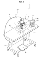
- FIG. 1 is a perspective view of an entire cloth bonding apparatus 1;
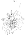
- FIG. 2 is a perspective view of a bonding device 2
- FIG. 3 is a front view of the bonding device 2
- FIG. 4 is a left side view of the bonding device 2;
- FIG. 5 is a perspective view of an internal configuration of the bonding device 2;
- FIG. 6 is a partially enlarged cross-sectional view of a storage chamber 18
- FIG. 7 is a partially enlarged perspective view showing the vicinity of a needle portion 70 of a lid portion 47;
- FIG. 8 is a partial cross-sectional view taken in the direction of arrows along a line II-II in FIG. 2 ;
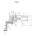
- FIG. 9 is a partial cross-sectional view taken in the direction of arrows along a line III-III in FIG. 2 ;
- FIG. 10 is a block diagram showing an electrical configuration of the cloth bonding apparatus 1;
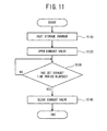
- FIG. 11 is a flowchart showing exhaust control processing
- FIG. 12 is a flowchart showing exhaust control processing
- FIG. 13 is a flowchart showing exhaust start time period setting processing.
- FIG. 1 A configuration of a cloth bonding apparatus 1 will be described with reference to FIG. 1 to FIG. 4 .
- the upper side, the lower side, the right side, the left side, the front side and the back side of FIG. 3 respectively correspond to the upper side, the lower side, the right side, the left side, the front side and the rear side of a bonding device 2.
- the cloth bonding apparatus 1 is provided with the bonding device 2, a control box 3, an operation panel 210 and a pedal 208.
- the bonding device 2 is fixed to a work table 220.
- the bonding device 2 attaches an adhesive 55 (refer to FIG. 6 ) between two layers of cloth that are arranged facing each other, and then presses and feeds the cloth.
- the two layers of cloth are bonded to each other by undergoing the above-described operation of the bonding device 2.
- the control box 3 is fixed below the work table 220.
- the control box 3 stores a control board on which is mounted a CPU 201 (refer to FIG. 10 ) and the like.
- the control box 3 is electrically connected to the bonding device 2, the operation panel 210 and the pedal 208.
- the operation panel 210 is provided on the right side of the bonding device 2.
- the operation panel 210 is provided with a liquid crystal display portion 207 that displays a variety of information, and keys 209 that receive various input settings by an operator.
- the pedal 208 is provided below the control box 3 and is used to adjust a feeding speed of the cloth.
- a compressor 217 is disposed below and on the left side of the work table 220.
- the compressor 217 and the bonding device 2 are connected by a hose 61.
- An end portion of the hose 61 on the bonding device 2 side is connected to a lid portion 47 (refer to FIG. 2 ) of a storage chamber 18.
- the hose 61 includes a valve 69, the inside of which can be opened and closed.
- the compressor 217 supplies pressurized gas to the bonding device 2 via the hose 61.
- the valve 69 controls circulation of the gas that is supplied by the compressor 217 into the storage chamber 18, and switches to one of an open state and a closed state.
- the bonding device 2 is provided with a bed portion 11, a pillar portion 12 and an arm portion 13.
- the bed portion 11 has a substantially cuboid shape.
- the pillar portion 12 extends vertically from the right end of the bed portion 11.
- the arm portion 13 is connected to the upper end of the pillar portion 12, and projects toward the left from a left side face of the pillar portion 12.
- a left end portion of the arm portion 13 supports a pump casing 14, the storage chamber 18 and a beam portion 19, in that order starting from the front.
- the pump casing 14 will be described. As shown in FIG. 2 and FIG. 3 , the pump casing 14 is provided with a first pump casing 31 and a second pump casing 32.
- the first pump casing 31 has a substantially cubic shape.
- the first pump casing 31 is fixed to the left side face of the arm portion 13.
- a gear pump 124 (refer to FIG. 5 ) and the like are provided inside the first pump casing 31.
- the gear pump 124 supplies an appropriate amount of the adhesive 55 (refer to FIG. 6 ) to a nozzle 17 at a high level of accuracy.
- the second pump casing 32 is a member having a substantially cuboid shape.
- the second pump casing 32 extends downward from a lower left end face of the first pump casing 31.
- An shaft portion 45 (refer to FIG. 3 ) is provided on the left side of the second pump casing 32.
- the shaft portion 45 is connected to the right side of an upper edge portion 162 of a support portion 16 such that the support portion 16 is swingably supported around the shaft portion 45.
- the pump casing 14 is provided with a supply passage 81 (refer to FIG. 8 ) and a supply passage 82 (refer to FIG. 8 ).
- the supply passage 81 feeds the adhesive 55 from the storage chamber 18 to the gear pump 124.
- the supply passage 82 feeds the adhesive 55 from the gear pump 124 to the support portion 16.
- the support portion 16 has a substantially cuboid shape.
- a slight gap is provided between a lower edge portion 164 of the support portion 16 and the bed portion 11.
- a supply passage 83 (refer to FIG. 9 ) is provided inside the support portion 16.
- the supply passage 83 supplies the adhesive 55 from the pump casing 14 to the nozzle 17.
- the nozzle 17 is provided on the lower edge portion 164 of the support portion 16.
- the nozzle 17 extends from the support portion 16 to the left side along the cloth, and the nozzle 17 includes a supply passage 84 (refer to FIG. 9 ) therein.
- the supply passage 84 is communicatively connected to the supply passage 83.
- a drive transmission portion 161 is provided on the upper edge portion 162 of the support portion 16.
- the drive transmission portion 161 supports a leading end portion of a movable portion 75 of an air cylinder 24.
- the nozzle 17 is cylindrically shaped.
- a discharge opening 86 (refer to FIG. 9 ), which discharges the adhesive 55, is provided on the lower side of the nozzle 17.
- the discharge opening 86 faces the bed portion 11.
- the gear pump 124 (refer to FIG. 5 ) supplies the adhesive 55 to the nozzle 17 via the supply passage 83 inside the support portion 16.
- the nozzle 17 discharges the adhesive 55 onto the cloth from the discharge opening 86.
- the adhesive 55 attaches to the surface of the cloth that is positioned underneath the nozzle 17.
- the storage chamber 18 has a substantially cuboid shape.
- the storage chamber 18 extends upward from the left side of the arm portion 13 and a rear side portion of the pump casing 14.
- the storage chamber 18 is provided with a main body 46 and the lid portion 47.
- the main body 46 has a bottomed tubular shape, of which an upper portion is open.
- the lid portion 47 covers the upper portion opening of the main body 46.
- the storage chamber 18 stores the thermal melting adhesive 55 in the main body 46.
- the cloth bonding apparatus 1 supplies the adhesive 55 stored in the storage chamber 18 to the gear pump 124 and the nozzle 17 as necessary.
- the thermal melting adhesive 55 liquefies when it is heated to a predetermined temperature, and it solidifies at a temperature lower than the predetermined temperature.
- the beam portion 19 is provided with a body portion 191, a spring support portion 193 and a column portion 192.
- the body portion 191 extends in a horizontal direction to the left from a left rear end portion of the arm portion 13.
- the spring support portion 193 is plate-shaped and extends in the horizontal direction toward the front from a left end portion of the body portion 191.
- the column portion 192 extends diagonally downward toward the front from the body portion 191, at an angle of approximately 45 degrees from the horizontal plane. A lower end portion of the column portion 192 is separated from the bed portion 11.
- the spring support portion 193 has a hole in its front end portion.
- the spring support portion 193 supports a shaft portion 51 such that the shaft portion 51 can move up and down.
- the shaft portion 51 is inserted through a spring 21.
- An upper end portion of the shaft portion 51 is inserted through the hole in the spring support portion 193.
- the column portion 192 includes a shaft portion 52 that extends in the horizontal direction to the left from a lower end portion of the column portion 192.
- the shaft portion 52 supports a rear end portion of a roller holding portion 20.
- the roller holding portion 20 pivots around the shaft portion 52 such that a front end portion of the roller holding portion 20 moves in the up-down direction.
- the body portion 191 includes the air cylinder 24 on the right side of the spring support portion 193. The air cylinder 24 switches a position of the support portion 16.
- the bonding device 2 is provided with a first motor 91, a second motor 92, a third motor 93 and the like in its interior.
- the first motor 91 drives the gear pump 124 by transmitting a rotational driving force to the gear pump 124 via a rotating shaft 121.
- the gear pump 124 is provided with a drive gear 122 and a driven gear 123.
- the drive gear 122 is fixed to a left end portion of the rotating shaft 121.
- the drive gear 122 rotates along with the rotating shaft 121.
- the driven gear 123 meshes with the drive gear 122.
- the first motor 91 is positioned inside the arm portion 13 and on the right side of a portion where the pump casing 14 is connected to the arm portion 13.
- the rotating shaft 121 extends, inside the pump casing 14, to the left from a rotating shaft of the first motor 91.
- the drive gear 122 and the driven gear 123 supply an appropriate amount of the adhesive 55 (refer to FIG. 6 ) to the nozzle 17.
- the second motor 92 drives an upper feed roller 22 by transmitting a rotational driving force to the upper feed roller 22 via a rotating shaft 126, a rotating shaft 127, a rotating shaft 128, a belt 129 and a belt 130.
- the second motor 92 is positioned inside the arm portion 13 and on the right side of a portion where the beam portion 19 is connected to the arm portion 13.
- the rotating shaft 126 extends to the left from a rotating shaft of the second motor 92, and penetrates inside the body portion 191.
- a left end portion of the rotating shaft 126 is positioned inside the column portion 192.
- the left end portion of the rotating shaft 126 supports a pulley.
- a right end portion of the rotating shaft 127 extends into the lower end portion of the column portion 192.
- a left end portion of the rotating shaft 127 extends into the rear end portion of the roller holding portion 20.
- the right end portion and the left end portion of the rotating shaft 127 respectively support pulleys.
- the rotating shaft 128 is a rotating shaft of the upper feed roller 22.
- a left end portion of the rotating shaft 128 extends into the front end portion of the roller holding portion 20, and supports a pulley.
- a right end portion of the rotating shaft 128 projects from the front end portion of the roller holding portion 20, and supports the upper feed roller 22.
- the belt 129 is stretched between the pulley of the left end portion of the rotating shaft 126 and the pulley of the right end portion of the rotating shaft 127 inside the column portion 192.
- the belt 130 is stretched between the pulley of the left end portion of the rotating shaft 127 and the pulley of the left end portion of the rotating shaft 128 inside the roller holding portion 20.
- the upper feed roller 22 rotates due to the rotation of the second motor 92.
- the third motor 93 drives a lower feed roller 25 by transmitting a rotational driving force to the lower feed roller 25 via a rotating shaft 141 and a belt 142.
- the lower feed roller 25 is cylindrically shaped and is fixed to the rotating shaft 141.
- the lower feed roller 25 is positioned below the upper feed roller 22 and inside the bed portion 11.
- a support bed 4 is provided inside the bed portion 11.
- the support bed 4 rotatably supports the rotating shaft 141.
- the belt 142 is stretched between a pulley of a rotating shaft of the third motor 93 and a pulley of the right end of the rotating shaft 141 inside the bed portion 11.
- the lower feed roller 25 rotates due to the rotation of the motor 93.
- the main body 46 of the storage chamber 18 is provided with a first heater 101 and a second heater 102.
- the first heater 101 and the second heater 102 heat the main body 46 so that the adhesive 55 stored in the main body 46 is heated.
- the bonding device 2 heats the thermal melting adhesive 55 to the predetermined temperature in the storage chamber 18, using the first heater 101 and the second heater 102, so that the adhesive 55 is liquefied.
- a third heater 103 is provided inside the first pump casing 31 of the pump casing 14.
- the third heater 103 heats the first pump casing 31 so as to heat the adhesive 55 flowing inside the first pump casing 31.
- a fourth heater 104 is provided inside the support portion 16. The fourth heater 104 heats the support portion 16 so as to heat the adhesive 55 flowing inside the support portion 16.
- the storage chamber 18 and a cartridge 60 will be described with reference to FIG. 6 .
- the storage chamber 18 houses the cartridge 60, which is filled with the adhesive 55, in the main body 46.
- the lid portion 47 is made of iron and it is attached by being screwed into the main body 46.
- the lid portion 47 covers the upper portion opening of the main body 46.
- the inside of the main body 46 is sealed in a state in which the lid portion 47 covers the upper portion opening (namely, in a state in which the lid portion 47 is closed). The operator removes the lid portion 47 from the main body 46 to insert and remove the cartridge 60.
- a gas supply port 49 is provided in a central portion of the lid portion 47.
- the gas supply port 49 is a hole that penetrates the lid portion 47 in the up-down direction.
- the lid portion 47 is provided with an intake pipe 48 that is connected to the gas supply port 49.
- a needle portion 70 is provided on a lower end portion of the lid portion 47.
- the needle portion 70 has a shape in which a leading end portion on the lower side is sharp.
- a cut-out portion 701 is provided in the outer periphery of the needle portion 70. The cut-out portion 701 extends from the vicinity of the leading end of the needle portion 70 toward the lower surface side of the lid portion 47.
- the gas supply port 49 passes through the inside of the needle portion 70 and extends to the vicinity of the leading end of the needle portion 70.
- the gas supply port 49 allows the gas supplied by the compressor 217 (refer to FIG. 1 ) to flow into the cartridge 60.
- the cut-out portion 701 can discharge the gas inside the cartridge 60 to the outside of the cartridge 60.
- the lid portion 47 is provided with a gas discharge port 72 on the left side of the gas supply port 49 (refer to FIG. 6 ).
- the gas discharge port 72 is a hole that passes through an upper surface and a lower surface of the lid portion 47.
- a passage diameter of the gas discharge port 72 is substantially the same as a passage diameter of the gas supply port 49.
- the lid portion 47 is provided with an exhaust pipe 71 that is connected to the gas discharge port 72.
- the exhaust pipe 71 is connected to an exhaust valve 73 (refer to FIG. 10 ) via a hose (not shown in the drawings).
- the exhaust valve 73 can be opened and closed by driving an exhaust solenoid 74.
- the storage chamber 18 discharges the gas inside the main body 46 to the outside of the storage chamber 18 via the gas discharge port 72.
- the lid portion 47 of the storage chamber 18 is closed and the exhaust valve 73 is in a closed state, gas is filled inside the storage chamber 18 and a pressure is generated that pushes the adhesive 55 in the cartridge 60 downward.
- the cartridge 60 is provided with a main body 54 and an inner lid 56 that are made of aluminum.
- the main body 54 has a substantially cylindrical shape.
- the adhesive 55 is filled inside the main body 54. When the lid portion 47 is closed, an upper surface of the main body 54 comes into contact with the lid portion 47.
- the inner lid 56 is provided inside the main body 54.
- the inner lid 56 can move downward in the main body 54, and comes into contact with an upper surface of the adhesive 55. By moving downward, the inner lid 56 can apply a downward pressure on the adhesive 55.
- a silica gel 62 is provided on the upper surface of the inner lid 56.
- the silica gel 62 is a desiccant that inhibits the adhesive 55 from being solidified by contact with gas that contains water in the cartridge 60.
- the silica gel 62 adsorbs water in the main body 54.
- the sharp leading end portion of the needle portion 70 of the lid portion 47 opens a hole 66 in an upper wall of the main body 54.
- the compressor 217 (refer to FIG. 1 ) feeds gas into the main body 54 via the hose 61 (refer to FIG. 1 ), the intake pipe 48 and the gas supply port 49. The gas pushes the inner lid 56 downward. The inner lid 56 pushes the adhesive 55 downward.
- the adhesive 55 flows from the storage chamber 18 via the pump casing 14 and the support portion 16 to the discharge opening 86 of the nozzle 17.
- the first heater 101 (refer to FIG. 5 ) and the second heater 102 (refer to FIG. 5 ) heat the adhesive 55 in the storage chamber 18.
- the adhesive 55 liquefies.
- the adhesive 55 in a liquefied state flows from the lower side of the cartridge 60 to the supply passage 81.
- the pedal 208 depresses the pedal 208 (refer to FIG. 1 )
- the first motor 91 drives the drive gear 122.
- the drive gear 122 and the driven gear 123 rotate.
- the gear pump 124 feeds the adhesive 55 in the liquefied state from the supply passage 81 toward the supply passage 82.
- the third heater 103 (refer to FIG. 5 ) heats the adhesive 55 flowing through the supply passages 81 and 82.
- the adhesive 55 maintains the liquefied state.
- the adhesive 55 flows from the supply passage 82 toward the supply passage 83, reaches the supply passage 84, and is discharged from the discharge opening 86 to the outside.
- the fourth heater 104 (refer to FIG. 5 ) heats the adhesive 55 flowing through the supply passage 83.
- the adhesive 55 in the liquefied state is discharged from the discharge opening 86 to the outside.
- the cloth bonding apparatus 1 is provided with the CPU 201, a ROM 202, a RAM 203 and a storage device 29.
- the CPU 201 performs reception processing and control processing.
- the reception processing is processing that receives input information from an input device including the keys 209 and the pedal 208.
- the reception processing is also processing that receives detection information detected by various types of sensors.
- the control processing is processing that controls the motors, the heaters and the like.
- the ROM 202 stores programs executed by the CPU 201 and various initial setting parameters etc.
- the RAM 203 temporarily stores data including a timer value, a counter value, flags and so on.
- the storage device 29 stores various setting information input by the operator.
- the CPU 201 is electrically connected to each of the ROM 202, the RAM 203 and the storage device 29, and can access each of their storage areas.
- the pedal 208 is electrically connected to the CPU 201.
- the CPU 201 recognizes an amount of depression of the pedal 208.
- the CPU 201 determines rotational speeds of the upper feed roller 22 and the lower feed roller 25 and a rotational speed of the drive gear 122, based on the recognized amount of depression of the pedal 208.
- the keys 209 are electrically connected to the CPU 201.
- the operator uses the keys 209 when performing various operation settings.
- the CPU 201 recognizes a state of depression of the keys 209.
- the CPU 201 stores information of the various operation settings in the storage device 29, based on the recognized state of depression of the keys 209.
- the first to fourth heaters 101 to 104 are each electrically connected to the CPU 201.
- the CPU 201 controls ON/OFF of each of the first to fourth heaters 101 to 104.
- the CPU 201 is electrically connected to the compressor 217.
- the CPU 201 controls ON/OFF of the compressor 217.
- a display driver 205 is electrically connected to the CPU 201.
- the display driver 205 is electrically connected to the liquid crystal display portion 207.
- the CPU 201 displays a desired image on the liquid crystal display portion 207 via the display driver 205.
- a motor driver 206 is electrically connected to the CPU 201.
- the first to third motors 91 to 93 are each electrically connected to the motor driver 206.
- the CPU 201 controls each of the first to third motors 91 to 93 via the motor driver 206.
- An air driver 204 is electrically connected to the CPU 201.
- the air driver 204 is electrically connected to the air cylinder 24.
- the CPU 201 controls a pressure of air fed into an air inlet of the air cylinder 24 via the air driver 204.
- the exhaust solenoid 74 is electrically connected to the CPU 201.
- the exhaust valve 73 is electrically connected to the exhaust solenoid 74.
- the CPU 201 controls opening/closing of the exhaust valve 73 by supplying a drive voltage to the exhaust solenoid 74.
- the exhaust control processing includes a first exhaust processing executed when a power source of the cloth bonding apparatus 1 is turned on, and a second exhaust processing executed when the operator performs a bonding operation.
- the first exhaust control processing executed is started when the power source of the cloth bonding apparatus 1 is turned on.
- the CPU 201 starts to drive the compressor 217 and supplies compressed gas into the cartridge 60 of the storage chamber 18.
- the CPU 201 turns on the first heater 101 and the second heater 102 to heat the main body 46 of the storage chamber 18 (step S110).
- the adhesive 55 in the storage chamber 18 liquefies at the predetermined temperature.
- the CPU 201 supplies a drive voltage to the exhaust solenoid 74 and thereby opens the exhaust valve 73 (step S120).
- the gas discharge port 72 discharges compressed gas filled in the main body 46 to the outside of the storage chamber 18, the compressed gas being fed from the cartridge 60 through the cut-out portion 701 into the main body 46.
- the power source is turned on, the gas discharge port 72 discharges gas containing water that remains in the cartridge 60 to the outside of the cartridge 60.
- the CPU 201 activates a timer at the same time as the opening of the exhaust valve 73.
- the CPU 201 determines whether a set exhaust time period has elapsed (step S130).
- the set exhaust time period is a time period during which the exhaust valve 73 is opened.
- the storage device 29 stores the set exhaust time period. When the set exhaust time period has not elapsed (no at step S130), the CPU 201 repeats the processing at step S130.
- the CPU 201 stops the supply of the drive voltage to the exhaust solenoid 74 and thereby closes the exhaust valve 73 (step S 140). The CPU 201 ends the processing.
- the second exhaust control processing executed is started when the operator depresses the pedal 208.
- the CPU 201 performs the bonding operation (step S210).
- the bonding operation includes the following operations: the CPU 201 performs drive control of the first to third motors 91 to 93 in accordance with the amount of depression of the pedal 208, the adhesive 55 (refer to FIG. 6 ) is supplied from the storage chamber 18 via the supply passages 81 to 84 to the nozzle 17 and is discharged from the nozzle 17 onto a cloth, and the cloth is pressed and fed.
- the CPU 201 determines whether the operator has released the operation of the pedal 208 (step S220). When the operator has not released the operation of the pedal 208 (no at step S220), the CPU 201 returns the processing to step S210 and the bonding operation is continued.
- step S220 When the operator has released the operation of the pedal 208 (yes at step S220), the CPU 201 activates the timer and determines whether the operator has operated the pedal 208 (step S230). When the operator has operated the pedal 208 (yes at step S230), the CPU201 returns the processing to step S210 and performs the bonding operation.
- step S240 determines whether an exhaust start time period has elapsed.
- the exhaust start time period is a time period from when the operator releases the operation of the pedal 208 to when the exhaust valve 73 is opened.
- the storage device 29 stores the exhaust start time period.
- the CPU 201 returns the processing to step S230.
- the CPU 201 supplies a drive voltage to the exhaust solenoid 74 and thereby opens the exhaust valve 73 (step S250).
- the gas discharge port 72 discharges compressed gas filled in the main body 46 to the outside of the storage chamber 18, the compressed gas being fed from the cartridge 60 through the cut-out portion 701 into the main body 46.
- the CPU 201 activates the timer at the same time as the opening of the exhaust valve 73.
- the CPU 201 determines whether the set exhaust time period has elapsed (step S260). When the set exhaust time period has not elapsed (no at step S260), the CPU 201 repeats the processing at step S260.
- the CPU 201 stops the supply of the drive voltage to the exhaust solenoid 74 and thereby closes the exhaust valve 73 (step S270). The CPU 201 ends the processing.
- the CPU 201 determines whether the operator has pressed a setting mode key (a predetermined key of the keys 209) of the cloth bonding apparatus 1 (step S310). When the operator has not pressed the setting mode key (no at step S310), the CPU 201 returns the processing to step S310. The CPU 201 continues to monitor the pressing of the setting mode key.
- a setting mode key a predetermined key of the keys 209 of the cloth bonding apparatus 1
- step S310 When the operator has pressed the setting mode key (yes at step S310), the CPU 201 determines whether the operator has operated the keys 209 and selected an input menu of the exhaust start time period, among input menus of various types of setting information (step S320). When the operator has selected an input menu other than the exhaust start time period (no at step S320), the CPU 201 returns the processing to step S310.
- the CPU 201 When the operator has selected the input menu of the exhaust start time period (yes at step S320), the CPU 201 temporarily stores, in the RAM 203, an input value of the exhaust start time period input by the operator via the keys 209 (step S330). The CPU 201 determines whether the operator has selected an OK key to confirm the input exhaust start time period (step S340). When the operator has not selected the OK key (no at step S340), the CPU 201 repeats the processing at step S340 and waits until the operator has selected the OK key. When the operator has selected the OK key (yes at step S340), the CPU 201 stores, in the storage device 29, the exhaust start time period stored in the RAM 203 at step S330 (step S350). The CPU 201 ends the processing.
- the cloth bonding apparatus 1 includes the gas discharge port 72 in the lid portion 47 of the storage chamber 18.
- the gas discharge port 72 discharges the gas containing water in the cartridge 60 to the outside of the storage chamber 18. Therefore, the cloth bonding apparatus 1 can inhibit the lid portion 47 etc. made of iron from rusting.
- the lid portion 47 is provided with the exhaust pipe 71 that is connected to the gas discharge port 72.
- the exhaust pipe 71 is connected to the exhaust valve 73 via the hose (not shown in the drawings).
- the CPU 201 performs drive control of the exhaust solenoid 74 and thereby opens and closes the exhaust valve 73. It is therefore possible to inhibit the gas discharge port 72 from being constantly opened. Therefore, the cloth bonding apparatus 1 can exchange the gas in the storage chamber 18 and can inhibit the gas containing water from accumulating in the storage chamber 18.
- the CPU 201 determines whether a time period during which the pedal 208 is stopped has reached the exhaust start time period. When the time period during which the pedal 208 is stopped has reached the exhaust start time period, the CPU 201 supplies a drive voltage to the exhaust solenoid 74 and thereby opens the exhaust valve 73. Therefore, when the time period during which the bonding operation is stopped is shorter than the set time period, the cloth bonding apparatus 1 can inhibit the exhaust valve 73 from switching to the open state. When the operator re-starts the bonding operation, the cloth bonding apparatus 1 can easily supply the adhesive 55 in the storage chamber 18 to the nozzle 17.
- the CPU 201 supplies a drive voltage to the exhaust solenoid 74 and thereby opens the exhaust valve 73.
- the water adsorbed by the silica gel 62 due to the heating of the main body 46 changes to vapor, and is filled in the storage chamber 18.
- the cloth bonding apparatus 1 can discharge the vapor to the outside of the storage chamber 18. Therefore, the cloth bonding apparatus 1 can inhibit the lid portion 47 etc. made of iron from rusting.
- the compressor 217 corresponds to a "pressure source” of the present disclosure.
- the exhaust valve 73 corresponds to a “discharge valve” of the present disclosure.
- the CPU 201 that performs the processing at step S120, step S140, step S250 and step S270 corresponds to a "discharge valve control portion" of the present disclosure.
- the supply passages 81 to 84, the first motor 91, the drive gear 122, the driven gear 123 and the gear pump 124 correspond to a "supply portion” of the present disclosure.
- the CPU 201 that performs the processing at step S210 corresponds to a "supply control portion" of the present disclosure.
- the pedal 208 corresponds to an "input portion" of the present disclosure.
- the CPU 201 that performs the processing at step S230 corresponds to a "measurement portion” of the present disclosure.
- the keys 209 and the CPU 201 that performs the exhaust start time period setting processing correspond to a "time setting portion” of the present disclosure.
- the first heater 101 and the second heater 102 correspond to a "heating portion” of the present disclosure.
- the CPU 201 that performs the processing at step S110 corresponds to a "heating control portion" of the present disclosure.
- the silica gel 62 corresponds to a "desiccant" of the present disclosure.
- the lid portion 47 may include the gas discharge port 72 on the right side of the gas supply port 49.
- the gas discharge port 72 may be provided in the central portion of the lid portion 47.
- the passage diameter of the gas discharge port 72 may be different from that of the gas supply port 49.
- a gas supply rate is higher than a gas discharge rate. Therefore, even when the cloth bonding apparatus 1 is not provided with the exhaust valve 73, downward pressure can be applied to the adhesive 55 in the cartridge 60. More specifically, the cloth bonding apparatus 1 can gradually discharge the gas in the storage chamber 18 or the cartridge 60 while applying downward pressure.
- the exhaust valve 73 may be opened and closed by the air cylinder 24.
- the exhaust valve 73 may be a cock or the like that can be opened and closed by a manual operation by the operator.
- the compressor 217 is not required for the cloth bonding apparatus 1.
- the hose 61 can be connected to the pressure source. In this case, the cloth bonding apparatus 1 can switch between supply and stop of pressure gas by opening and closing the valve 69.
- the cloth bonding apparatus 1 may be adapted such that the set exhaust time period can be set similarly to the setting of the exhaust start time period.
Landscapes
- Engineering & Computer Science (AREA)
- Mechanical Engineering (AREA)
- Textile Engineering (AREA)
- Treatment Of Fiber Materials (AREA)
- Coating Apparatus (AREA)
- Adhesives Or Adhesive Processes (AREA)
Abstract
Description
- The present disclosure relates to a cloth bonding apparatus including a storage chamber that stores an adhesive.
- A cloth bonding apparatus discharges a heated liquid adhesive from a nozzle. The adhesive attaches to a cloth. An operator overlays a cloth to be bonded on the cloth to which the adhesive is attached. The cloth bonding apparatus presses both the cloths, and bonds the cloth and the cloth with the adhesive, thereby reducing unevenness of a thread that occurs on a cloth surface during sewing.
- For example, a cloth bonding apparatus described in Japanese Laid-Open Patent Publication No.
2010-222764 - In the bonding apparatus described in the above-described Japanese Laid-Open Patent Publication No.
2010-222764 - The thermal melting adhesive reacts with water and solidifies. Once the adhesive solidifies, it cannot be liquefied. If the gas containing water accumulates in the storage chamber, the adhesive in the storage chamber reacts with the water and solidifies. The solidified adhesive cannot be ejected from the nozzle.
- It is an object of the present disclosure to provide a cloth bonding apparatus that is capable of inhibiting gas containing water from accumulating in a storage chamber.
- A cloth bonding apparatus according to the present disclosure includes: a storage chamber which has an opening and which is adapted to stores an adhesive; a lid portion which is provided on the opening of the storage chamber and which is capable of opening and closing the opening; a gas supply port which is provided in the lid portion and which is adapted to supply gas into the storage chamber; and a pressure source which is adapted to supply the gas through the gas supply port into the storage chamber, thereby extruding the adhesive in the storage chamber. The cloth bonding apparatus is characterized by including a gas discharge port which is adapted to discharge the gas in the storage chamber to an outside of the storage chamber.
- The gas discharge port is adapted to discharge the gas containing water in the storage chamber to the outside of the storage chamber. Therefore, the cloth bonding apparatus can inhibit a metal component from rusting.
- The cloth bonding apparatus may further include: a discharge valve which is adapted to open and close the gas discharge port, and which discharges the gas in the storage chamber to the outside of the storage chamber by opening the gas discharge port; and a discharge valve control portion which controls switching between opening and closing of the discharge valve.
- The discharge valve control portion that controls the discharge valve inhibits the gas discharge port from being constantly opened. Therefore, the cloth bonding apparatus can exchange the gas in the storage chamber and can inhibit the gas containing water from accumulating in the storage chamber.
- The cloth bonding apparatus may further include: a nozzle which has an adhesive discharge opening through which the adhesive is dischargeable; a supply portion which, in case where the pressure source supplies the gas through the gas supply port into the storage chamber, is adapted to supply the nozzle with the adhesive extruded from the storage chamber; and a supply control portion which controls driving of the supply portion. The discharge valve control portion may switch the discharge valve to an open state in case where the supply control portion stops supply of the adhesive by the supply portion.
- In case where the supply of the adhesive to the nozzle is stopped, the discharge valve control portion switches the discharge valve to the open state. Therefore, when bonding is not performed, the cloth bonding apparatus can discharge the gas in the storage chamber to the outside of the storage chamber. The cloth bonding apparatus can inhibit gas from being discharged through the gas discharge port when bonding is performed, and can inhibit a lack of the pressure that is necessary to extrude the adhesive in the storage chamber.
- The cloth bonding apparatus may further include: an input portion which starts and stops the driving of the supply portion by the supply control portion; a measurement portion which measures an elapsed time from when the input portion stops the driving of the supply portion by the supply control portion; and a time setting portion which sets a time period from when the input portion stops the driving of the supply portion by the supply control portion to when the discharge valve control portion switches the discharge valve to the open state. The discharge valve control portion may switch the discharge valve to the open state in case where the elapsed time has reached the time period set by the time setting portion.
- In case where the elapsed time from when the drive of the supply portion is stopped reaches the time period set by the time setting portion, the discharge valve control portion switches the discharge valve to the open state. Therefore, when a time period during which the supply portion is stopped is shorter than the set time period, the cloth bonding apparatus can inhibit the discharge valve from switching to the open state. When the drive of the supply portion is re-started, the cloth bonding apparatus can easily supply the adhesive in the storage chamber to the nozzle.
- The cloth bonding apparatus my further include a heating portion which is adapted to heat the adhesive in the storage chamber; and a heating control portion which controls driving of the heating portion. The discharge valve control portion may switch the discharge valve to the open state in case where the heating portion has heated the adhesive in the storage chamber to a predetermined temperature in accordance with control by the heating control portion.
- In case where the heating position heats the adhesive in the storage chamber to the predetermined temperature, the discharge valve control portion switches the discharge valve to the open state. Therefore, the cloth bonding apparatus can discharge the gas containing water that is generated by heating in the storage chamber to the outside of the storage chamber, and can inhibit a metal component from rusting.
- The storage chamber may be adapted to detachably house a cartridge which stores the adhesive, and the cartridge may be adapted to include a desiccant which adsorbs water in the cartridge. The gas supply port may be adapted to supply the gas from the pressure source into the cartridge, and the gas discharge port may be adapted to discharge the gas in the cartridge to the outside of the storage chamber.
- The storage chamber may be adapted to detachably houses the cartridge which stores the adhesive. The cartridge may be adapted to include the desiccant which inhibits the adhesive from reacting with water and the state of the adhesive from changing. Therefore, the cloth bonding apparatus can discharge, through the gas discharge port, the gas containing water that cannot be sufficiently absorbed by the desiccant.
- The lid portion may include the gas discharge port and a needle portion which is adapted to form a hole in the cartridge, the hole being used to supply the gas from the pressure source into the cartridge. The needle portion may include a cut-out portion in an outer periphery, the cut-out portion being adapted to discharge the gas in the cartridge to the outside of the cartridge. The gas supply port may pass through an internal portion of the needle portion.
- The lid portion may include the needle portion which is adapted to form a hole in the cartridge. The hole is used to supply the gas from the pressure source into the cartridge. The needle portion may include the cut-out portion in its outer periphery. The cut-out portion may discharge the gas in the cartridge to the outside of the cartridge. Therefore, the cloth bonding apparatus allows the gas in the cartridge to easily flow from the cut-out portion to the gas discharge port provided in the lid portion.
- Exemplary embodiments of the present disclosure will be described below in detail with reference to the accompanying drawings in which:
-
FIG. 1 is a perspective view of an entirecloth bonding apparatus 1; -
FIG. 2 is a perspective view of abonding device 2; -
FIG. 3 is a front view of thebonding device 2; -
FIG. 4 is a left side view of thebonding device 2; -
FIG. 5 is a perspective view of an internal configuration of thebonding device 2; -
FIG. 6 is a partially enlarged cross-sectional view of astorage chamber 18; -
FIG. 7 is a partially enlarged perspective view showing the vicinity of aneedle portion 70 of alid portion 47; -
FIG. 8 is a partial cross-sectional view taken in the direction of arrows along a line II-II inFIG. 2 ; -
FIG. 9 is a partial cross-sectional view taken in the direction of arrows along a line III-III inFIG. 2 ; -
FIG. 10 is a block diagram showing an electrical configuration of thecloth bonding apparatus 1; -
FIG. 11 is a flowchart showing exhaust control processing; -
FIG. 12 is a flowchart showing exhaust control processing; and -
FIG. 13 is a flowchart showing exhaust start time period setting processing. - An embodiment of the present disclosure will be described below with reference to the drawings.
- A configuration of a
cloth bonding apparatus 1 will be described with reference toFIG. 1 to FIG. 4 . The upper side, the lower side, the right side, the left side, the front side and the back side ofFIG. 3 respectively correspond to the upper side, the lower side, the right side, the left side, the front side and the rear side of abonding device 2. - An overall configuration of the
cloth bonding apparatus 1 will be described with reference toFIG. 1 . As shown inFIG. 1 , thecloth bonding apparatus 1 is provided with thebonding device 2, acontrol box 3, anoperation panel 210 and apedal 208. Thebonding device 2 is fixed to a work table 220. Thebonding device 2 attaches an adhesive 55 (refer toFIG. 6 ) between two layers of cloth that are arranged facing each other, and then presses and feeds the cloth. The two layers of cloth are bonded to each other by undergoing the above-described operation of thebonding device 2. - The
control box 3 is fixed below the work table 220. Thecontrol box 3 stores a control board on which is mounted a CPU 201 (refer toFIG. 10 ) and the like. Thecontrol box 3 is electrically connected to thebonding device 2, theoperation panel 210 and thepedal 208. Theoperation panel 210 is provided on the right side of thebonding device 2. Theoperation panel 210 is provided with a liquidcrystal display portion 207 that displays a variety of information, andkeys 209 that receive various input settings by an operator. Thepedal 208 is provided below thecontrol box 3 and is used to adjust a feeding speed of the cloth. - A
compressor 217 is disposed below and on the left side of the work table 220. Thecompressor 217 and thebonding device 2 are connected by ahose 61. An end portion of thehose 61 on thebonding device 2 side is connected to a lid portion 47 (refer toFIG. 2 ) of astorage chamber 18. Thehose 61 includes avalve 69, the inside of which can be opened and closed. Thecompressor 217 supplies pressurized gas to thebonding device 2 via thehose 61. Thevalve 69 controls circulation of the gas that is supplied by thecompressor 217 into thestorage chamber 18, and switches to one of an open state and a closed state. - A configuration of the
bonding device 2 will be described with reference toFIG. 2 to FIG. 4 . As shown inFIG. 2 andFIG. 3 , thebonding device 2 is provided with abed portion 11, apillar portion 12 and anarm portion 13. Thebed portion 11 has a substantially cuboid shape. Thepillar portion 12 extends vertically from the right end of thebed portion 11. Thearm portion 13 is connected to the upper end of thepillar portion 12, and projects toward the left from a left side face of thepillar portion 12. - As shown in
FIG. 2 , a left end portion of thearm portion 13 supports apump casing 14, thestorage chamber 18 and abeam portion 19, in that order starting from the front. - The
pump casing 14 will be described. As shown inFIG. 2 andFIG. 3 , thepump casing 14 is provided with afirst pump casing 31 and asecond pump casing 32. Thefirst pump casing 31 has a substantially cubic shape. Thefirst pump casing 31 is fixed to the left side face of thearm portion 13. A gear pump 124 (refer toFIG. 5 ) and the like are provided inside thefirst pump casing 31. Thegear pump 124 supplies an appropriate amount of the adhesive 55 (refer toFIG. 6 ) to anozzle 17 at a high level of accuracy. Thesecond pump casing 32 is a member having a substantially cuboid shape. Thesecond pump casing 32 extends downward from a lower left end face of thefirst pump casing 31. - An shaft portion 45 (refer to
FIG. 3 ) is provided on the left side of thesecond pump casing 32. Theshaft portion 45 is connected to the right side of anupper edge portion 162 of asupport portion 16 such that thesupport portion 16 is swingably supported around theshaft portion 45. Thepump casing 14 is provided with a supply passage 81 (refer toFIG. 8 ) and a supply passage 82 (refer toFIG. 8 ). Thesupply passage 81 feeds the adhesive 55 from thestorage chamber 18 to thegear pump 124. Thesupply passage 82 feeds the adhesive 55 from thegear pump 124 to thesupport portion 16. - As shown in
FIG. 2 andFIG. 3 , thesupport portion 16 has a substantially cuboid shape. A slight gap is provided between alower edge portion 164 of thesupport portion 16 and thebed portion 11. A supply passage 83 (refer toFIG. 9 ) is provided inside thesupport portion 16. Thesupply passage 83 supplies the adhesive 55 from thepump casing 14 to thenozzle 17. Thenozzle 17 is provided on thelower edge portion 164 of thesupport portion 16. Thenozzle 17 extends from thesupport portion 16 to the left side along the cloth, and thenozzle 17 includes a supply passage 84 (refer toFIG. 9 ) therein. Thesupply passage 84 is communicatively connected to thesupply passage 83. Adrive transmission portion 161 is provided on theupper edge portion 162 of thesupport portion 16. Thedrive transmission portion 161 supports a leading end portion of amovable portion 75 of anair cylinder 24. - The
nozzle 17 is cylindrically shaped. A discharge opening 86 (refer toFIG. 9 ), which discharges the adhesive 55, is provided on the lower side of thenozzle 17. When the operator performs a cloth bonding operation, thedischarge opening 86 faces thebed portion 11. When the bonding operation is performed, the operator inserts thenozzle 17 between two layers of cloth that are arranged facing each other. The gear pump 124 (refer toFIG. 5 ) supplies the adhesive 55 to thenozzle 17 via thesupply passage 83 inside thesupport portion 16. Thenozzle 17 discharges the adhesive 55 onto the cloth from thedischarge opening 86. The adhesive 55 attaches to the surface of the cloth that is positioned underneath thenozzle 17. - As shown in
FIG. 2 andFIG. 3 , thestorage chamber 18 has a substantially cuboid shape. Thestorage chamber 18 extends upward from the left side of thearm portion 13 and a rear side portion of thepump casing 14. Thestorage chamber 18 is provided with amain body 46 and thelid portion 47. Themain body 46 has a bottomed tubular shape, of which an upper portion is open. Thelid portion 47 covers the upper portion opening of themain body 46. Thestorage chamber 18 stores thethermal melting adhesive 55 in themain body 46. Thecloth bonding apparatus 1 supplies the adhesive 55 stored in thestorage chamber 18 to thegear pump 124 and thenozzle 17 as necessary. Thethermal melting adhesive 55 liquefies when it is heated to a predetermined temperature, and it solidifies at a temperature lower than the predetermined temperature. - As shown in
FIG. 2 , thebeam portion 19 is provided with abody portion 191, aspring support portion 193 and acolumn portion 192. Thebody portion 191 extends in a horizontal direction to the left from a left rear end portion of thearm portion 13. Thespring support portion 193 is plate-shaped and extends in the horizontal direction toward the front from a left end portion of thebody portion 191. As shown inFIG. 2 andFIG. 4 , thecolumn portion 192 extends diagonally downward toward the front from thebody portion 191, at an angle of approximately 45 degrees from the horizontal plane. A lower end portion of thecolumn portion 192 is separated from thebed portion 11. - As shown in
FIG. 2 , thespring support portion 193 has a hole in its front end portion. Thespring support portion 193 supports ashaft portion 51 such that theshaft portion 51 can move up and down. Theshaft portion 51 is inserted through aspring 21. An upper end portion of theshaft portion 51 is inserted through the hole in thespring support portion 193. Thecolumn portion 192 includes ashaft portion 52 that extends in the horizontal direction to the left from a lower end portion of thecolumn portion 192. Theshaft portion 52 supports a rear end portion of aroller holding portion 20. Theroller holding portion 20 pivots around theshaft portion 52 such that a front end portion of theroller holding portion 20 moves in the up-down direction. Thebody portion 191 includes theair cylinder 24 on the right side of thespring support portion 193. Theair cylinder 24 switches a position of thesupport portion 16. - An internal configuration of the
bonding device 2 will be described with reference toFIG. 5 . Thebonding device 2 is provided with afirst motor 91, asecond motor 92, athird motor 93 and the like in its interior. - The
first motor 91 drives thegear pump 124 by transmitting a rotational driving force to thegear pump 124 via arotating shaft 121. Thegear pump 124 is provided with adrive gear 122 and a drivengear 123. Thedrive gear 122 is fixed to a left end portion of therotating shaft 121. Thedrive gear 122 rotates along with therotating shaft 121. The drivengear 123 meshes with thedrive gear 122. Thefirst motor 91 is positioned inside thearm portion 13 and on the right side of a portion where thepump casing 14 is connected to thearm portion 13. Therotating shaft 121 extends, inside thepump casing 14, to the left from a rotating shaft of thefirst motor 91. Thedrive gear 122 and the drivengear 123 supply an appropriate amount of the adhesive 55 (refer toFIG. 6 ) to thenozzle 17. - The
second motor 92 drives anupper feed roller 22 by transmitting a rotational driving force to theupper feed roller 22 via arotating shaft 126, arotating shaft 127, arotating shaft 128, abelt 129 and abelt 130. Thesecond motor 92 is positioned inside thearm portion 13 and on the right side of a portion where thebeam portion 19 is connected to thearm portion 13. - The
rotating shaft 126 extends to the left from a rotating shaft of thesecond motor 92, and penetrates inside thebody portion 191. A left end portion of therotating shaft 126 is positioned inside thecolumn portion 192. The left end portion of therotating shaft 126 supports a pulley. A right end portion of therotating shaft 127 extends into the lower end portion of thecolumn portion 192. A left end portion of therotating shaft 127 extends into the rear end portion of theroller holding portion 20. The right end portion and the left end portion of therotating shaft 127 respectively support pulleys. Therotating shaft 128 is a rotating shaft of theupper feed roller 22. A left end portion of therotating shaft 128 extends into the front end portion of theroller holding portion 20, and supports a pulley. A right end portion of therotating shaft 128 projects from the front end portion of theroller holding portion 20, and supports theupper feed roller 22. Thebelt 129 is stretched between the pulley of the left end portion of therotating shaft 126 and the pulley of the right end portion of therotating shaft 127 inside thecolumn portion 192. Thebelt 130 is stretched between the pulley of the left end portion of therotating shaft 127 and the pulley of the left end portion of therotating shaft 128 inside theroller holding portion 20. Theupper feed roller 22 rotates due to the rotation of thesecond motor 92. - The
third motor 93 drives alower feed roller 25 by transmitting a rotational driving force to thelower feed roller 25 via arotating shaft 141 and abelt 142. Thelower feed roller 25 is cylindrically shaped and is fixed to therotating shaft 141. Thelower feed roller 25 is positioned below theupper feed roller 22 and inside thebed portion 11. Asupport bed 4 is provided inside thebed portion 11. Thesupport bed 4 rotatably supports therotating shaft 141. Thebelt 142 is stretched between a pulley of a rotating shaft of thethird motor 93 and a pulley of the right end of therotating shaft 141 inside thebed portion 11. Thelower feed roller 25 rotates due to the rotation of themotor 93. - The
main body 46 of thestorage chamber 18 is provided with afirst heater 101 and asecond heater 102. Thefirst heater 101 and thesecond heater 102 heat themain body 46 so that the adhesive 55 stored in themain body 46 is heated. Thebonding device 2 heats thethermal melting adhesive 55 to the predetermined temperature in thestorage chamber 18, using thefirst heater 101 and thesecond heater 102, so that the adhesive 55 is liquefied. - A
third heater 103 is provided inside thefirst pump casing 31 of thepump casing 14. Thethird heater 103 heats thefirst pump casing 31 so as to heat the adhesive 55 flowing inside thefirst pump casing 31. Afourth heater 104 is provided inside thesupport portion 16. Thefourth heater 104 heats thesupport portion 16 so as to heat the adhesive 55 flowing inside thesupport portion 16. - The
storage chamber 18 and acartridge 60 will be described with reference toFIG. 6 . Thestorage chamber 18 houses thecartridge 60, which is filled with the adhesive 55, in themain body 46. Thelid portion 47 is made of iron and it is attached by being screwed into themain body 46. Thelid portion 47 covers the upper portion opening of themain body 46. The inside of themain body 46 is sealed in a state in which thelid portion 47 covers the upper portion opening (namely, in a state in which thelid portion 47 is closed). The operator removes thelid portion 47 from themain body 46 to insert and remove thecartridge 60. - A
gas supply port 49 is provided in a central portion of thelid portion 47. Thegas supply port 49 is a hole that penetrates thelid portion 47 in the up-down direction. Thelid portion 47 is provided with anintake pipe 48 that is connected to thegas supply port 49. Aneedle portion 70 is provided on a lower end portion of thelid portion 47. Theneedle portion 70 has a shape in which a leading end portion on the lower side is sharp. As shown inFIG. 7 , a cut-outportion 701 is provided in the outer periphery of theneedle portion 70. The cut-outportion 701 extends from the vicinity of the leading end of theneedle portion 70 toward the lower surface side of thelid portion 47. Thegas supply port 49 passes through the inside of theneedle portion 70 and extends to the vicinity of the leading end of theneedle portion 70. Thegas supply port 49 allows the gas supplied by the compressor 217 (refer toFIG. 1 ) to flow into thecartridge 60. The cut-outportion 701 can discharge the gas inside thecartridge 60 to the outside of thecartridge 60. - The
lid portion 47 is provided with agas discharge port 72 on the left side of the gas supply port 49 (refer toFIG. 6 ). Thegas discharge port 72 is a hole that passes through an upper surface and a lower surface of thelid portion 47. A passage diameter of thegas discharge port 72 is substantially the same as a passage diameter of thegas supply port 49. Thelid portion 47 is provided with anexhaust pipe 71 that is connected to thegas discharge port 72. Theexhaust pipe 71 is connected to an exhaust valve 73 (refer toFIG. 10 ) via a hose (not shown in the drawings). Theexhaust valve 73 can be opened and closed by driving anexhaust solenoid 74. When theexhaust solenoid 74 opens theexhaust valve 73, thestorage chamber 18 discharges the gas inside themain body 46 to the outside of thestorage chamber 18 via thegas discharge port 72. When thelid portion 47 of thestorage chamber 18 is closed and theexhaust valve 73 is in a closed state, gas is filled inside thestorage chamber 18 and a pressure is generated that pushes the adhesive 55 in thecartridge 60 downward. - The
cartridge 60 is provided with amain body 54 and aninner lid 56 that are made of aluminum. Themain body 54 has a substantially cylindrical shape. The adhesive 55 is filled inside themain body 54. When thelid portion 47 is closed, an upper surface of themain body 54 comes into contact with thelid portion 47. - The
inner lid 56 is provided inside themain body 54. Theinner lid 56 can move downward in themain body 54, and comes into contact with an upper surface of the adhesive 55. By moving downward, theinner lid 56 can apply a downward pressure on the adhesive 55. Asilica gel 62 is provided on the upper surface of theinner lid 56. Thesilica gel 62 is a desiccant that inhibits the adhesive 55 from being solidified by contact with gas that contains water in thecartridge 60. Thesilica gel 62 adsorbs water in themain body 54. - The sharp leading end portion of the
needle portion 70 of thelid portion 47 opens ahole 66 in an upper wall of themain body 54. The compressor 217 (refer toFIG. 1 ) feeds gas into themain body 54 via the hose 61 (refer toFIG. 1 ), theintake pipe 48 and thegas supply port 49. The gas pushes theinner lid 56 downward. Theinner lid 56 pushes the adhesive 55 downward. - With reference to
FIG. 8 andFIG. 9 , the flow of the adhesive 55 (refer toFIG. 6 ) will be described. The adhesive 55 flows from thestorage chamber 18 via thepump casing 14 and thesupport portion 16 to the discharge opening 86 of thenozzle 17. The first heater 101 (refer toFIG. 5 ) and the second heater 102 (refer toFIG. 5 ) heat the adhesive 55 in thestorage chamber 18. The adhesive 55 liquefies. The adhesive 55 in a liquefied state flows from the lower side of thecartridge 60 to thesupply passage 81. When the operator depresses the pedal 208 (refer toFIG. 1 ), thefirst motor 91 drives thedrive gear 122. Thedrive gear 122 and the drivengear 123 rotate. Thegear pump 124 feeds the adhesive 55 in the liquefied state from thesupply passage 81 toward thesupply passage 82. The third heater 103 (refer toFIG. 5 ) heats the adhesive 55 flowing through thesupply passages - The adhesive 55 flows from the
supply passage 82 toward thesupply passage 83, reaches thesupply passage 84, and is discharged from thedischarge opening 86 to the outside. The fourth heater 104 (refer toFIG. 5 ) heats the adhesive 55 flowing through thesupply passage 83. The adhesive 55 in the liquefied state is discharged from thedischarge opening 86 to the outside. - An electrical configuration of the
cloth bonding apparatus 1 will be described with reference toFIG. 10 . Thecloth bonding apparatus 1 is provided with the CPU 201, aROM 202, aRAM 203 and astorage device 29. The CPU 201 performs reception processing and control processing. The reception processing is processing that receives input information from an input device including thekeys 209 and thepedal 208. The reception processing is also processing that receives detection information detected by various types of sensors. The control processing is processing that controls the motors, the heaters and the like. - The
ROM 202 stores programs executed by the CPU 201 and various initial setting parameters etc. TheRAM 203 temporarily stores data including a timer value, a counter value, flags and so on. Thestorage device 29 stores various setting information input by the operator. The CPU 201 is electrically connected to each of theROM 202, theRAM 203 and thestorage device 29, and can access each of their storage areas. - The
pedal 208 is electrically connected to the CPU 201. The CPU 201 recognizes an amount of depression of thepedal 208. The CPU 201 determines rotational speeds of theupper feed roller 22 and thelower feed roller 25 and a rotational speed of thedrive gear 122, based on the recognized amount of depression of thepedal 208. - The
keys 209 are electrically connected to the CPU 201. The operator uses thekeys 209 when performing various operation settings. The CPU 201 recognizes a state of depression of thekeys 209. The CPU 201 stores information of the various operation settings in thestorage device 29, based on the recognized state of depression of thekeys 209. - The first to
fourth heaters 101 to 104 are each electrically connected to the CPU 201. The CPU 201 controls ON/OFF of each of the first tofourth heaters 101 to 104. The CPU 201 is electrically connected to thecompressor 217. The CPU 201 controls ON/OFF of thecompressor 217. - A
display driver 205 is electrically connected to the CPU 201. Thedisplay driver 205 is electrically connected to the liquidcrystal display portion 207. The CPU 201 displays a desired image on the liquidcrystal display portion 207 via thedisplay driver 205. - A
motor driver 206 is electrically connected to the CPU 201. The first tothird motors 91 to 93 are each electrically connected to themotor driver 206. The CPU 201 controls each of the first tothird motors 91 to 93 via themotor driver 206. - An
air driver 204 is electrically connected to the CPU 201. Theair driver 204 is electrically connected to theair cylinder 24. The CPU 201 controls a pressure of air fed into an air inlet of theair cylinder 24 via theair driver 204. - The
exhaust solenoid 74 is electrically connected to the CPU 201. Theexhaust valve 73 is electrically connected to theexhaust solenoid 74. The CPU 201 controls opening/closing of theexhaust valve 73 by supplying a drive voltage to theexhaust solenoid 74. - Exhaust control processing of the
cloth bonding apparatus 1 will be described with reference toFIG. 11 andFIG. 12 . The reference numerals Si (i = 110, 120...) in the figures indicate respective steps. The exhaust control processing includes a first exhaust processing executed when a power source of thecloth bonding apparatus 1 is turned on, and a second exhaust processing executed when the operator performs a bonding operation. - As shown in
FIG. 11 , the first exhaust control processing executed is started when the power source of thecloth bonding apparatus 1 is turned on. When the power source is turned on, the CPU 201 starts to drive thecompressor 217 and supplies compressed gas into thecartridge 60 of thestorage chamber 18. The CPU 201 turns on thefirst heater 101 and thesecond heater 102 to heat themain body 46 of the storage chamber 18 (step S110). The adhesive 55 in thestorage chamber 18 liquefies at the predetermined temperature. - The CPU 201 supplies a drive voltage to the
exhaust solenoid 74 and thereby opens the exhaust valve 73 (step S120). When theexhaust valve 73 is opened, thegas discharge port 72 discharges compressed gas filled in themain body 46 to the outside of thestorage chamber 18, the compressed gas being fed from thecartridge 60 through the cut-outportion 701 into themain body 46. When the power source is turned on, thegas discharge port 72 discharges gas containing water that remains in thecartridge 60 to the outside of thecartridge 60. The CPU 201 activates a timer at the same time as the opening of theexhaust valve 73. The CPU 201 determines whether a set exhaust time period has elapsed (step S130). The set exhaust time period is a time period during which theexhaust valve 73 is opened. Thestorage device 29 stores the set exhaust time period. When the set exhaust time period has not elapsed (no at step S130), the CPU 201 repeats the processing at step S130. - When the set exhaust time period has elapsed (yes at step S130), the CPU 201 stops the supply of the drive voltage to the
exhaust solenoid 74 and thereby closes the exhaust valve 73 (step S 140). The CPU 201 ends the processing. - As shown in
FIG. 12 , the second exhaust control processing executed is started when the operator depresses thepedal 208. The CPU 201 performs the bonding operation (step S210). The bonding operation includes the following operations: the CPU 201 performs drive control of the first tothird motors 91 to 93 in accordance with the amount of depression of thepedal 208, the adhesive 55 (refer toFIG. 6 ) is supplied from thestorage chamber 18 via thesupply passages 81 to 84 to thenozzle 17 and is discharged from thenozzle 17 onto a cloth, and the cloth is pressed and fed. - The CPU 201 determines whether the operator has released the operation of the pedal 208 (step S220). When the operator has not released the operation of the pedal 208 (no at step S220), the CPU 201 returns the processing to step S210 and the bonding operation is continued.
- When the operator has released the operation of the pedal 208 (yes at step S220), the CPU 201 activates the timer and determines whether the operator has operated the pedal 208 (step S230). When the operator has operated the pedal 208 (yes at step S230), the CPU201 returns the processing to step S210 and performs the bonding operation.
- When the operator has not operated the pedal 208 (no at step S230), the CPU 201 determines whether an exhaust start time period has elapsed (step S240). The exhaust start time period is a time period from when the operator releases the operation of the pedal 208 to when the
exhaust valve 73 is opened. Thestorage device 29 stores the exhaust start time period. When the exhaust start time period has not elapsed (no at step S240), the CPU 201 returns the processing to step S230. - When the exhaust start time period has elapsed (yes at step S240), the CPU 201 supplies a drive voltage to the
exhaust solenoid 74 and thereby opens the exhaust valve 73 (step S250). When theexhaust valve 73 is opened, thegas discharge port 72 discharges compressed gas filled in themain body 46 to the outside of thestorage chamber 18, the compressed gas being fed from thecartridge 60 through the cut-outportion 701 into themain body 46. The CPU 201 activates the timer at the same time as the opening of theexhaust valve 73. The CPU 201 determines whether the set exhaust time period has elapsed (step S260). When the set exhaust time period has not elapsed (no at step S260), the CPU 201 repeats the processing at step S260. - When the set exhaust time period has elapsed (yes at step S260), the CPU 201 stops the supply of the drive voltage to the
exhaust solenoid 74 and thereby closes the exhaust valve 73 (step S270). The CPU 201 ends the processing. - Exhaust start time period setting processing will be described with reference to
FIG. 13 . The CPU 201 determines whether the operator has pressed a setting mode key (a predetermined key of the keys 209) of the cloth bonding apparatus 1 (step S310). When the operator has not pressed the setting mode key (no at step S310), the CPU 201 returns the processing to step S310. The CPU 201 continues to monitor the pressing of the setting mode key. - When the operator has pressed the setting mode key (yes at step S310), the CPU 201 determines whether the operator has operated the
keys 209 and selected an input menu of the exhaust start time period, among input menus of various types of setting information (step S320). When the operator has selected an input menu other than the exhaust start time period (no at step S320), the CPU 201 returns the processing to step S310. - When the operator has selected the input menu of the exhaust start time period (yes at step S320), the CPU 201 temporarily stores, in the
RAM 203, an input value of the exhaust start time period input by the operator via the keys 209 (step S330). The CPU 201 determines whether the operator has selected an OK key to confirm the input exhaust start time period (step S340). When the operator has not selected the OK key (no at step S340), the CPU 201 repeats the processing at step S340 and waits until the operator has selected the OK key. When the operator has selected the OK key (yes at step S340), the CPU 201 stores, in thestorage device 29, the exhaust start time period stored in theRAM 203 at step S330 (step S350). The CPU 201 ends the processing. - As described above, in the present embodiment, the
cloth bonding apparatus 1 includes thegas discharge port 72 in thelid portion 47 of thestorage chamber 18. Thegas discharge port 72 discharges the gas containing water in thecartridge 60 to the outside of thestorage chamber 18. Therefore, thecloth bonding apparatus 1 can inhibit thelid portion 47 etc. made of iron from rusting. - The
lid portion 47 is provided with theexhaust pipe 71 that is connected to thegas discharge port 72. Theexhaust pipe 71 is connected to theexhaust valve 73 via the hose (not shown in the drawings). The CPU 201 performs drive control of theexhaust solenoid 74 and thereby opens and closes theexhaust valve 73. It is therefore possible to inhibit thegas discharge port 72 from being constantly opened. Therefore, thecloth bonding apparatus 1 can exchange the gas in thestorage chamber 18 and can inhibit the gas containing water from accumulating in thestorage chamber 18. - When it is determined that the operator has not operated the
pedal 208, the CPU 201 determines whether a time period during which thepedal 208 is stopped has reached the exhaust start time period. When the time period during which thepedal 208 is stopped has reached the exhaust start time period, the CPU 201 supplies a drive voltage to theexhaust solenoid 74 and thereby opens theexhaust valve 73. Therefore, when the time period during which the bonding operation is stopped is shorter than the set time period, thecloth bonding apparatus 1 can inhibit theexhaust valve 73 from switching to the open state. When the operator re-starts the bonding operation, thecloth bonding apparatus 1 can easily supply the adhesive 55 in thestorage chamber 18 to thenozzle 17. - After the
main body 46 of thestorage chamber 18 is heated by turning on thefirst heater 101 and thesecond heater 102, the CPU 201 supplies a drive voltage to theexhaust solenoid 74 and thereby opens theexhaust valve 73. The water adsorbed by thesilica gel 62 due to the heating of themain body 46 changes to vapor, and is filled in thestorage chamber 18. However, thecloth bonding apparatus 1 can discharge the vapor to the outside of thestorage chamber 18. Therefore, thecloth bonding apparatus 1 can inhibit thelid portion 47 etc. made of iron from rusting. - The
compressor 217 corresponds to a "pressure source" of the present disclosure. Theexhaust valve 73 corresponds to a "discharge valve" of the present disclosure. The CPU 201 that performs the processing at step S120, step S140, step S250 and step S270 corresponds to a "discharge valve control portion" of the present disclosure. Thesupply passages 81 to 84, thefirst motor 91, thedrive gear 122, the drivengear 123 and thegear pump 124 correspond to a "supply portion" of the present disclosure. The CPU 201 that performs the processing at step S210 corresponds to a "supply control portion" of the present disclosure. Thepedal 208 corresponds to an "input portion" of the present disclosure. The CPU 201 that performs the processing at step S230 corresponds to a "measurement portion" of the present disclosure. Thekeys 209 and the CPU 201 that performs the exhaust start time period setting processing correspond to a "time setting portion" of the present disclosure. Thefirst heater 101 and thesecond heater 102 correspond to a "heating portion" of the present disclosure. The CPU 201 that performs the processing at step S110 corresponds to a "heating control portion" of the present disclosure. Thesilica gel 62 corresponds to a "desiccant" of the present disclosure. - The present disclosure is not limited to the above-described embodiment and various changes can be made. The
lid portion 47 may include thegas discharge port 72 on the right side of thegas supply port 49. Thegas discharge port 72 may be provided in the central portion of thelid portion 47. - The passage diameter of the
gas discharge port 72 may be different from that of thegas supply port 49. When the passage diameter of thegas discharge port 72 is smaller than that of thegas supply port 49, a gas supply rate is higher than a gas discharge rate. Therefore, even when thecloth bonding apparatus 1 is not provided with theexhaust valve 73, downward pressure can be applied to the adhesive 55 in thecartridge 60. More specifically, thecloth bonding apparatus 1 can gradually discharge the gas in thestorage chamber 18 or thecartridge 60 while applying downward pressure. - The
exhaust valve 73 may be opened and closed by theair cylinder 24. Theexhaust valve 73 may be a cock or the like that can be opened and closed by a manual operation by the operator. - When a pressure source is provided in a factory in which the
cloth bonding apparatus 1 is installed, thecompressor 217 is not required for thecloth bonding apparatus 1. When thecloth bonding apparatus 1 uses the pressure source of the factory, thehose 61 can be connected to the pressure source. In this case, thecloth bonding apparatus 1 can switch between supply and stop of pressure gas by opening and closing thevalve 69. - The
cloth bonding apparatus 1 may be adapted such that the set exhaust time period can be set similarly to the setting of the exhaust start time period.
Claims (7)
- A cloth bonding apparatus (1), comprising:a storage chamber (18) which has an opening and which is adapted to stores an adhesive (55);a lid portion (47) which is provided on the opening of the storage chamber and which is capable of opening and closing the opening;a gas supply port (49) which is provided in the lid portion and which is adapted to supply gas into the storage chamber; anda pressure source (217) which is adapted to supply the gas through the gas supply port into the storage chamber, thereby extruding the adhesive in the storage chamber, the cloth bonding apparatus being characterized by comprisinga gas discharge port (72) which is adapted to discharge the gas in the storage chamber to an outside of the storage chamber.
- The cloth bonding apparatus according to claim 1, further comprising:a discharge valve (73) which is adapted to open and close the gas discharge port, and which discharges the gas in the storage chamber to the outside of the storage chamber by opening the gas discharge port; anda discharge valve control portion (201) which controls switching between opening and closing of the discharge valve.
- The cloth bonding apparatus according to claim 2, further comprising:a nozzle (17) which has an adhesive discharge opening (86) through which the adhesive is dischargeable;a supply portion (81 to 84, 91, 122, 123, 124) which, in case where the pressure source supplies the gas through the gas supply port into the storage chamber, is adapted to supply the nozzle with the adhesive extruded from the storage chamber; anda supply control portion (201) which controls driving of the supply portion,whereinthe discharge valve control portion switches the discharge valve to an open state in case where the supply control portion stops supply of the adhesive by the supply portion.
- The cloth bonding apparatus according to claim 3, further comprising:an input portion (208) which starts and stops the driving of the supply portion by the supply control portion;a measurement portion (201) which measures an elapsed time from when the input portion stops the driving of the supply portion by the supply control portion; anda time setting portion (201) which sets a time period from when the input portion stops the driving of the supply portion by the supply control portion to when the discharge valve control portion switches the discharge valve to the open state,whereinthe discharge valve control portion switches the discharge valve to the open state in case where the elapsed time has reached the time period set by the time setting portion.
- The cloth bonding apparatus according to any one of claims 2 through 4, further comprising:a heating portion (101, 102) which is adapted to heat the adhesive in the storage chamber; anda heating control portion (201) which controls driving of the heating portion,whereinthe discharge valve control portion switches the discharge valve to the open state in case where the heating portion has heated the adhesive in the storage chamber to a predetermined temperature in accordance with control by the heating control portion.
- The cloth bonding apparatus according to any one of claims 1 through 5, wherein:the storage chamber is adapted to detachably house a cartridge (60) which stores the adhesive;the cartridge is adapted to include a desiccant (62) which adsorbs water in the cartridge;the gas supply port is adapted to supply the gas from the pressure source into the cartridge; andthe gas discharge port is adapted to discharge the gas in the cartridge to the outside of the storage chamber.
- The cloth bonding apparatus according to claim 6, wherein:the lid portion includes the gas discharge port and a needle portion (70) which is adapted to form a hole (66) in the cartridge, the hole being used to supply the gas from the pressure source into the cartridge;the needle portion includes a cut-out portion (701) in an outer periphery, the cut-out portion being adapted to discharge the gas in the cartridge to the outside of the cartridge; andthe gas supply port passes through an internal portion of the needle portion.
Applications Claiming Priority (1)
| Application Number | Priority Date | Filing Date | Title |
|---|---|---|---|
| JP2010266164A JP5533602B2 (en) | 2010-11-30 | 2010-11-30 | Cloth bonding equipment |
Publications (3)
| Publication Number | Publication Date |
|---|---|
| EP2457458A2 true EP2457458A2 (en) | 2012-05-30 |
| EP2457458A3 EP2457458A3 (en) | 2013-01-02 |
| EP2457458B1 EP2457458B1 (en) | 2014-01-29 |
Family
ID=45044416
Family Applications (1)
| Application Number | Title | Priority Date | Filing Date |
|---|---|---|---|
| EP11191149.1A Not-in-force EP2457458B1 (en) | 2010-11-30 | 2011-11-29 | Cloth bonding apparatus |
Country Status (3)
| Country | Link |
|---|---|
| EP (1) | EP2457458B1 (en) |
| JP (1) | JP5533602B2 (en) |
| CN (1) | CN102477701B (en) |
Cited By (1)
| Publication number | Priority date | Publication date | Assignee | Title |
|---|---|---|---|---|
| CN111713768A (en) * | 2020-05-25 | 2020-09-29 | 武汉捷盛经贸有限责任公司 | Cuff-adjustable suit-dress and manufacturing method thereof |
Citations (1)
| Publication number | Priority date | Publication date | Assignee | Title |
|---|---|---|---|---|
| JP2010222764A (en) | 2009-03-25 | 2010-10-07 | Brother Ind Ltd | Cloth bonding apparatus and lid control program |
Family Cites Families (6)
| Publication number | Priority date | Publication date | Assignee | Title |
|---|---|---|---|---|
| FR1344985A (en) * | 1962-10-02 | 1963-12-06 | S E T E P Soc D Etudes | Method and devices for welding seams of coated felt-type floor coverings |
| JP2004148183A (en) * | 2002-10-30 | 2004-05-27 | Toray Eng Co Ltd | Coating method and coating equipment |
| US20060043102A1 (en) * | 2004-08-31 | 2006-03-02 | Keller Marc L | Method and apparatus for applying solvent |
| JP2010222763A (en) * | 2009-03-25 | 2010-10-07 | Brother Ind Ltd | Cloth bonding apparatus and pressure control program |
| EP2233277B1 (en) * | 2009-03-25 | 2014-07-16 | Brother Kogyo Kabushiki Kaisha | Cloth bonding apparatus |
| JP2010222762A (en) * | 2009-03-25 | 2010-10-07 | Brother Ind Ltd | Cloth bonding equipment |
-
2010
- 2010-11-30 JP JP2010266164A patent/JP5533602B2/en active Active
-
2011
- 2011-11-17 CN CN201110386335.8A patent/CN102477701B/en active Active
- 2011-11-29 EP EP11191149.1A patent/EP2457458B1/en not_active Not-in-force
Patent Citations (1)
| Publication number | Priority date | Publication date | Assignee | Title |
|---|---|---|---|---|
| JP2010222764A (en) | 2009-03-25 | 2010-10-07 | Brother Ind Ltd | Cloth bonding apparatus and lid control program |
Cited By (2)
| Publication number | Priority date | Publication date | Assignee | Title |
|---|---|---|---|---|
| CN111713768A (en) * | 2020-05-25 | 2020-09-29 | 武汉捷盛经贸有限责任公司 | Cuff-adjustable suit-dress and manufacturing method thereof |
| CN111713768B (en) * | 2020-05-25 | 2024-01-05 | 武汉捷盛经贸有限责任公司 | Women's dress with adjustable cuffs and manufacturing method thereof |
Also Published As
| Publication number | Publication date |
|---|---|
| JP2012117166A (en) | 2012-06-21 |
| CN102477701A (en) | 2012-05-30 |
| JP5533602B2 (en) | 2014-06-25 |
| CN102477701B (en) | 2014-07-23 |
| EP2457458A3 (en) | 2013-01-02 |
| EP2457458B1 (en) | 2014-01-29 |
Similar Documents
| Publication | Publication Date | Title |
|---|---|---|
| EP2990184B1 (en) | Cloth bonding apparatus | |
| CN202466265U (en) | Cloth adhering device | |
| EP2216164B1 (en) | Cloth bonding apparatus | |
| EP2366297B1 (en) | Cloth bonding apparatus | |
| EP2216162B1 (en) | Cloth bonding apparatus | |
| EP2233276B1 (en) | Cloth bonding apparatus | |
| EP2233278B1 (en) | Cloth bonding apparatus | |
| EP2457458B1 (en) | Cloth bonding apparatus | |
| EP2361750B1 (en) | Cloth bonding apparatus and cartridge | |
| EP3075276A1 (en) | Bonding device and bonding device control method | |
| EP2233277A1 (en) | Cloth bonding apparatus | |
| JP5713128B2 (en) | Cloth bonding equipment | |
| KR20060059632A (en) | Various types of ice manufacturing apparatus and control method | |
| EP2255955B1 (en) | Cloth bonding apparatus | |
| JP2010222764A (en) | Cloth bonding apparatus and lid control program | |
| EP2457457B1 (en) | Cloth bonding apparatus and bonding method | |
| JP5321485B2 (en) | Cloth bonding equipment | |
| JP5463989B2 (en) | Cloth bonding apparatus and cartridge | |
| JP5505006B2 (en) | Cloth bonding apparatus and cartridge removal method |
Legal Events
| Date | Code | Title | Description |
|---|---|---|---|
| PUAI | Public reference made under article 153(3) epc to a published international application that has entered the european phase |
Free format text: ORIGINAL CODE: 0009012 |
|
| AK | Designated contracting states |
Kind code of ref document: A2 Designated state(s): AL AT BE BG CH CY CZ DE DK EE ES FI FR GB GR HR HU IE IS IT LI LT LU LV MC MK MT NL NO PL PT RO RS SE SI SK SM TR |
|
| AX | Request for extension of the european patent |
Extension state: BA ME |
|
| PUAL | Search report despatched |
Free format text: ORIGINAL CODE: 0009013 |
|
| AK | Designated contracting states |
Kind code of ref document: A3 Designated state(s): AL AT BE BG CH CY CZ DE DK EE ES FI FR GB GR HR HU IE IS IT LI LT LU LV MC MK MT NL NO PL PT RO RS SE SI SK SM TR |
|
| AX | Request for extension of the european patent |
Extension state: BA ME |
|
| RIC1 | Information provided on ipc code assigned before grant |
Ipc: A41H 43/04 20060101AFI20121126BHEP Ipc: A41D 27/24 20060101ALN20121126BHEP Ipc: B29C 65/52 20060101ALI20121126BHEP Ipc: D06H 5/00 20060101ALI20121126BHEP |
|
| 17P | Request for examination filed |
Effective date: 20130624 |
|
| RBV | Designated contracting states (corrected) |
Designated state(s): AL AT BE BG CH CY CZ DE DK EE ES FI FR GB GR HR HU IE IS IT LI LT LU LV MC MK MT NL NO PL PT RO RS SE SI SK SM TR |
|
| RIC1 | Information provided on ipc code assigned before grant |
Ipc: B29C 65/52 20060101ALI20130718BHEP Ipc: A41H 43/04 20060101AFI20130718BHEP Ipc: A41D 27/24 20060101ALN20130718BHEP Ipc: D06H 5/00 20060101ALI20130718BHEP |
|
| GRAP | Despatch of communication of intention to grant a patent |
Free format text: ORIGINAL CODE: EPIDOSNIGR1 |
|
| INTG | Intention to grant announced |
Effective date: 20130911 |
|
| GRAS | Grant fee paid |
Free format text: ORIGINAL CODE: EPIDOSNIGR3 |
|
| GRAA | (expected) grant |
Free format text: ORIGINAL CODE: 0009210 |
|
| AK | Designated contracting states |
Kind code of ref document: B1 Designated state(s): AL AT BE BG CH CY CZ DE DK EE ES FI FR GB GR HR HU IE IS IT LI LT LU LV MC MK MT NL NO PL PT RO RS SE SI SK SM TR |
|
| REG | Reference to a national code |
Ref country code: GB Ref legal event code: FG4D |
|
| REG | Reference to a national code |
Ref country code: CH Ref legal event code: EP |
|
| REG | Reference to a national code |
Ref country code: AT Ref legal event code: REF Ref document number: 651296 Country of ref document: AT Kind code of ref document: T Effective date: 20140215 |
|
| REG | Reference to a national code |
Ref country code: IE Ref legal event code: FG4D |
|
| REG | Reference to a national code |
Ref country code: DE Ref legal event code: R096 Ref document number: 602011004859 Country of ref document: DE Effective date: 20140313 |
|
| REG | Reference to a national code |
Ref country code: AT Ref legal event code: MK05 Ref document number: 651296 Country of ref document: AT Kind code of ref document: T Effective date: 20140129 |
|
| REG | Reference to a national code |
Ref country code: NL Ref legal event code: VDEP Effective date: 20140129 |
|
| REG | Reference to a national code |
Ref country code: LT Ref legal event code: MG4D |
|
| PG25 | Lapsed in a contracting state [announced via postgrant information from national office to epo] |
Ref country code: IS Free format text: LAPSE BECAUSE OF FAILURE TO SUBMIT A TRANSLATION OF THE DESCRIPTION OR TO PAY THE FEE WITHIN THE PRESCRIBED TIME-LIMIT Effective date: 20140529 Ref country code: LT Free format text: LAPSE BECAUSE OF FAILURE TO SUBMIT A TRANSLATION OF THE DESCRIPTION OR TO PAY THE FEE WITHIN THE PRESCRIBED TIME-LIMIT Effective date: 20140129 Ref country code: NO Free format text: LAPSE BECAUSE OF FAILURE TO SUBMIT A TRANSLATION OF THE DESCRIPTION OR TO PAY THE FEE WITHIN THE PRESCRIBED TIME-LIMIT Effective date: 20140429 |
|
| PG25 | Lapsed in a contracting state [announced via postgrant information from national office to epo] |
Ref country code: AT Free format text: LAPSE BECAUSE OF FAILURE TO SUBMIT A TRANSLATION OF THE DESCRIPTION OR TO PAY THE FEE WITHIN THE PRESCRIBED TIME-LIMIT Effective date: 20140129 Ref country code: PT Free format text: LAPSE BECAUSE OF FAILURE TO SUBMIT A TRANSLATION OF THE DESCRIPTION OR TO PAY THE FEE WITHIN THE PRESCRIBED TIME-LIMIT Effective date: 20140529 Ref country code: NL Free format text: LAPSE BECAUSE OF FAILURE TO SUBMIT A TRANSLATION OF THE DESCRIPTION OR TO PAY THE FEE WITHIN THE PRESCRIBED TIME-LIMIT Effective date: 20140129 Ref country code: FI Free format text: LAPSE BECAUSE OF FAILURE TO SUBMIT A TRANSLATION OF THE DESCRIPTION OR TO PAY THE FEE WITHIN THE PRESCRIBED TIME-LIMIT Effective date: 20140129 Ref country code: SE Free format text: LAPSE BECAUSE OF FAILURE TO SUBMIT A TRANSLATION OF THE DESCRIPTION OR TO PAY THE FEE WITHIN THE PRESCRIBED TIME-LIMIT Effective date: 20140129 Ref country code: ES Free format text: LAPSE BECAUSE OF FAILURE TO SUBMIT A TRANSLATION OF THE DESCRIPTION OR TO PAY THE FEE WITHIN THE PRESCRIBED TIME-LIMIT Effective date: 20140129 Ref country code: CY Free format text: LAPSE BECAUSE OF FAILURE TO SUBMIT A TRANSLATION OF THE DESCRIPTION OR TO PAY THE FEE WITHIN THE PRESCRIBED TIME-LIMIT Effective date: 20140129 |
|
| PG25 | Lapsed in a contracting state [announced via postgrant information from national office to epo] |
Ref country code: HR Free format text: LAPSE BECAUSE OF FAILURE TO SUBMIT A TRANSLATION OF THE DESCRIPTION OR TO PAY THE FEE WITHIN THE PRESCRIBED TIME-LIMIT Effective date: 20140129 Ref country code: BE Free format text: LAPSE BECAUSE OF FAILURE TO SUBMIT A TRANSLATION OF THE DESCRIPTION OR TO PAY THE FEE WITHIN THE PRESCRIBED TIME-LIMIT Effective date: 20140129 Ref country code: RS Free format text: LAPSE BECAUSE OF FAILURE TO SUBMIT A TRANSLATION OF THE DESCRIPTION OR TO PAY THE FEE WITHIN THE PRESCRIBED TIME-LIMIT Effective date: 20140129 Ref country code: LV Free format text: LAPSE BECAUSE OF FAILURE TO SUBMIT A TRANSLATION OF THE DESCRIPTION OR TO PAY THE FEE WITHIN THE PRESCRIBED TIME-LIMIT Effective date: 20140129 |
|
| REG | Reference to a national code |
Ref country code: DE Ref legal event code: R097 Ref document number: 602011004859 Country of ref document: DE |
|
| PG25 | Lapsed in a contracting state [announced via postgrant information from national office to epo] |
Ref country code: DK Free format text: LAPSE BECAUSE OF FAILURE TO SUBMIT A TRANSLATION OF THE DESCRIPTION OR TO PAY THE FEE WITHIN THE PRESCRIBED TIME-LIMIT Effective date: 20140129 Ref country code: RO Free format text: LAPSE BECAUSE OF FAILURE TO SUBMIT A TRANSLATION OF THE DESCRIPTION OR TO PAY THE FEE WITHIN THE PRESCRIBED TIME-LIMIT Effective date: 20140129 Ref country code: CZ Free format text: LAPSE BECAUSE OF FAILURE TO SUBMIT A TRANSLATION OF THE DESCRIPTION OR TO PAY THE FEE WITHIN THE PRESCRIBED TIME-LIMIT Effective date: 20140129 Ref country code: EE Free format text: LAPSE BECAUSE OF FAILURE TO SUBMIT A TRANSLATION OF THE DESCRIPTION OR TO PAY THE FEE WITHIN THE PRESCRIBED TIME-LIMIT Effective date: 20140129 |
|
| PG25 | Lapsed in a contracting state [announced via postgrant information from national office to epo] |
Ref country code: PL Free format text: LAPSE BECAUSE OF FAILURE TO SUBMIT A TRANSLATION OF THE DESCRIPTION OR TO PAY THE FEE WITHIN THE PRESCRIBED TIME-LIMIT Effective date: 20140129 Ref country code: SK Free format text: LAPSE BECAUSE OF FAILURE TO SUBMIT A TRANSLATION OF THE DESCRIPTION OR TO PAY THE FEE WITHIN THE PRESCRIBED TIME-LIMIT Effective date: 20140129 |
|
| PLBE | No opposition filed within time limit |
Free format text: ORIGINAL CODE: 0009261 |
|
| STAA | Information on the status of an ep patent application or granted ep patent |
Free format text: STATUS: NO OPPOSITION FILED WITHIN TIME LIMIT |
|
| 26N | No opposition filed |
Effective date: 20141030 |
|
| REG | Reference to a national code |
Ref country code: DE Ref legal event code: R097 Ref document number: 602011004859 Country of ref document: DE Effective date: 20141030 |
|
| PG25 | Lapsed in a contracting state [announced via postgrant information from national office to epo] |
Ref country code: SI Free format text: LAPSE BECAUSE OF FAILURE TO SUBMIT A TRANSLATION OF THE DESCRIPTION OR TO PAY THE FEE WITHIN THE PRESCRIBED TIME-LIMIT Effective date: 20140129 |
|
| PG25 | Lapsed in a contracting state [announced via postgrant information from national office to epo] |
Ref country code: MC Free format text: LAPSE BECAUSE OF FAILURE TO SUBMIT A TRANSLATION OF THE DESCRIPTION OR TO PAY THE FEE WITHIN THE PRESCRIBED TIME-LIMIT Effective date: 20140129 Ref country code: LU Free format text: LAPSE BECAUSE OF FAILURE TO SUBMIT A TRANSLATION OF THE DESCRIPTION OR TO PAY THE FEE WITHIN THE PRESCRIBED TIME-LIMIT Effective date: 20141129 |
|
| REG | Reference to a national code |
Ref country code: CH Ref legal event code: PL |
|
| PG25 | Lapsed in a contracting state [announced via postgrant information from national office to epo] |
Ref country code: CH Free format text: LAPSE BECAUSE OF NON-PAYMENT OF DUE FEES Effective date: 20141130 Ref country code: LI Free format text: LAPSE BECAUSE OF NON-PAYMENT OF DUE FEES Effective date: 20141130 |
|
| REG | Reference to a national code |
Ref country code: IE Ref legal event code: MM4A |
|
| REG | Reference to a national code |
Ref country code: FR Ref legal event code: ST Effective date: 20150731 |
|
| PG25 | Lapsed in a contracting state [announced via postgrant information from national office to epo] |
Ref country code: IE Free format text: LAPSE BECAUSE OF NON-PAYMENT OF DUE FEES Effective date: 20141129 |
|
| PG25 | Lapsed in a contracting state [announced via postgrant information from national office to epo] |
Ref country code: FR Free format text: LAPSE BECAUSE OF NON-PAYMENT OF DUE FEES Effective date: 20141201 |
|
| PG25 | Lapsed in a contracting state [announced via postgrant information from national office to epo] |
Ref country code: SM Free format text: LAPSE BECAUSE OF FAILURE TO SUBMIT A TRANSLATION OF THE DESCRIPTION OR TO PAY THE FEE WITHIN THE PRESCRIBED TIME-LIMIT Effective date: 20140129 |
|
| PG25 | Lapsed in a contracting state [announced via postgrant information from national office to epo] |
Ref country code: BG Free format text: LAPSE BECAUSE OF FAILURE TO SUBMIT A TRANSLATION OF THE DESCRIPTION OR TO PAY THE FEE WITHIN THE PRESCRIBED TIME-LIMIT Effective date: 20140129 Ref country code: GR Free format text: LAPSE BECAUSE OF FAILURE TO SUBMIT A TRANSLATION OF THE DESCRIPTION OR TO PAY THE FEE WITHIN THE PRESCRIBED TIME-LIMIT Effective date: 20140430 |
|
| PG25 | Lapsed in a contracting state [announced via postgrant information from national office to epo] |
Ref country code: HU Free format text: LAPSE BECAUSE OF FAILURE TO SUBMIT A TRANSLATION OF THE DESCRIPTION OR TO PAY THE FEE WITHIN THE PRESCRIBED TIME-LIMIT; INVALID AB INITIO Effective date: 20111129 Ref country code: TR Free format text: LAPSE BECAUSE OF FAILURE TO SUBMIT A TRANSLATION OF THE DESCRIPTION OR TO PAY THE FEE WITHIN THE PRESCRIBED TIME-LIMIT Effective date: 20140129 Ref country code: MT Free format text: LAPSE BECAUSE OF FAILURE TO SUBMIT A TRANSLATION OF THE DESCRIPTION OR TO PAY THE FEE WITHIN THE PRESCRIBED TIME-LIMIT Effective date: 20140129 |
|
| PG25 | Lapsed in a contracting state [announced via postgrant information from national office to epo] |
Ref country code: MK Free format text: LAPSE BECAUSE OF FAILURE TO SUBMIT A TRANSLATION OF THE DESCRIPTION OR TO PAY THE FEE WITHIN THE PRESCRIBED TIME-LIMIT Effective date: 20140129 |
|
| PG25 | Lapsed in a contracting state [announced via postgrant information from national office to epo] |
Ref country code: AL Free format text: LAPSE BECAUSE OF FAILURE TO SUBMIT A TRANSLATION OF THE DESCRIPTION OR TO PAY THE FEE WITHIN THE PRESCRIBED TIME-LIMIT Effective date: 20140129 |
|
| PGFP | Annual fee paid to national office [announced via postgrant information from national office to epo] |
Ref country code: DE Payment date: 20181015 Year of fee payment: 8 |
|
| PGFP | Annual fee paid to national office [announced via postgrant information from national office to epo] |
Ref country code: IT Payment date: 20181119 Year of fee payment: 8 Ref country code: GB Payment date: 20181025 Year of fee payment: 8 |
|
| REG | Reference to a national code |
Ref country code: DE Ref legal event code: R119 Ref document number: 602011004859 Country of ref document: DE |
|
| GBPC | Gb: european patent ceased through non-payment of renewal fee |
Effective date: 20191129 |
|
| PG25 | Lapsed in a contracting state [announced via postgrant information from national office to epo] |
Ref country code: GB Free format text: LAPSE BECAUSE OF NON-PAYMENT OF DUE FEES Effective date: 20191129 Ref country code: DE Free format text: LAPSE BECAUSE OF NON-PAYMENT OF DUE FEES Effective date: 20200603 Ref country code: IT Free format text: LAPSE BECAUSE OF NON-PAYMENT OF DUE FEES Effective date: 20191129 |