EP2457082B1 - Method for evaluating shaped charge perforation test cores using computer tomographic images thereof - Google Patents
Method for evaluating shaped charge perforation test cores using computer tomographic images thereof Download PDFInfo
- Publication number
- EP2457082B1 EP2457082B1 EP10765702.5A EP10765702A EP2457082B1 EP 2457082 B1 EP2457082 B1 EP 2457082B1 EP 10765702 A EP10765702 A EP 10765702A EP 2457082 B1 EP2457082 B1 EP 2457082B1
- Authority
- EP
- European Patent Office
- Prior art keywords
- sample
- rock formation
- physical property
- perforation tunnel
- formation
- Prior art date
- Legal status (The legal status is an assumption and is not a legal conclusion. Google has not performed a legal analysis and makes no representation as to the accuracy of the status listed.)
- Not-in-force
Links
- 238000000034 method Methods 0.000 title claims description 46
- 238000012360 testing method Methods 0.000 title claims description 29
- 230000015572 biosynthetic process Effects 0.000 claims description 64
- 239000011435 rock Substances 0.000 claims description 55
- 239000012530 fluid Substances 0.000 claims description 28
- 230000000704 physical effect Effects 0.000 claims description 13
- 238000004088 simulation Methods 0.000 claims description 9
- 230000035699 permeability Effects 0.000 claims description 7
- 239000002360 explosive Substances 0.000 claims description 5
- 230000004075 alteration Effects 0.000 claims description 3
- 230000000694 effects Effects 0.000 claims description 3
- 230000000052 comparative effect Effects 0.000 claims 1
- 238000005755 formation reaction Methods 0.000 description 53
- 238000005553 drilling Methods 0.000 description 12
- 238000002591 computed tomography Methods 0.000 description 11
- 239000011148 porous material Substances 0.000 description 9
- 238000004458 analytical method Methods 0.000 description 7
- 101000609947 Homo sapiens Rod cGMP-specific 3',5'-cyclic phosphodiesterase subunit alpha Proteins 0.000 description 6
- 102100039177 Rod cGMP-specific 3',5'-cyclic phosphodiesterase subunit alpha Human genes 0.000 description 6
- 238000011156 evaluation Methods 0.000 description 6
- 238000009826 distribution Methods 0.000 description 5
- 239000000463 material Substances 0.000 description 5
- 239000004568 cement Substances 0.000 description 4
- 238000005520 cutting process Methods 0.000 description 4
- 238000005474 detonation Methods 0.000 description 4
- 230000008569 process Effects 0.000 description 4
- 239000008186 active pharmaceutical agent Substances 0.000 description 3
- 238000002347 injection Methods 0.000 description 3
- 239000007924 injection Substances 0.000 description 3
- 239000002245 particle Substances 0.000 description 3
- 239000013049 sediment Substances 0.000 description 3
- 239000004575 stone Substances 0.000 description 3
- 239000013077 target material Substances 0.000 description 3
- 239000004215 Carbon black (E152) Substances 0.000 description 2
- 229910000831 Steel Inorganic materials 0.000 description 2
- 230000009471 action Effects 0.000 description 2
- 230000008901 benefit Effects 0.000 description 2
- 238000012512 characterization method Methods 0.000 description 2
- 238000004140 cleaning Methods 0.000 description 2
- 238000004590 computer program Methods 0.000 description 2
- 238000013461 design Methods 0.000 description 2
- 230000006870 function Effects 0.000 description 2
- 229930195733 hydrocarbon Natural products 0.000 description 2
- 150000002430 hydrocarbons Chemical class 0.000 description 2
- 238000003384 imaging method Methods 0.000 description 2
- VNWKTOKETHGBQD-UHFFFAOYSA-N methane Chemical compound C VNWKTOKETHGBQD-UHFFFAOYSA-N 0.000 description 2
- 238000010603 microCT Methods 0.000 description 2
- 230000004660 morphological change Effects 0.000 description 2
- 239000003208 petroleum Substances 0.000 description 2
- 239000010959 steel Substances 0.000 description 2
- 238000010998 test method Methods 0.000 description 2
- 238000005481 NMR spectroscopy Methods 0.000 description 1
- 230000004323 axial length Effects 0.000 description 1
- 239000004566 building material Substances 0.000 description 1
- 230000008859 change Effects 0.000 description 1
- 238000010835 comparative analysis Methods 0.000 description 1
- 230000006835 compression Effects 0.000 description 1
- 238000007906 compression Methods 0.000 description 1
- 238000013170 computed tomography imaging Methods 0.000 description 1
- 230000001143 conditioned effect Effects 0.000 description 1
- 239000000470 constituent Substances 0.000 description 1
- 238000011109 contamination Methods 0.000 description 1
- 230000008878 coupling Effects 0.000 description 1
- 238000010168 coupling process Methods 0.000 description 1
- 238000005859 coupling reaction Methods 0.000 description 1
- 239000003822 epoxy resin Substances 0.000 description 1
- 230000004907 flux Effects 0.000 description 1
- 150000004677 hydrates Chemical class 0.000 description 1
- 229910052500 inorganic mineral Inorganic materials 0.000 description 1
- 238000003780 insertion Methods 0.000 description 1
- 230000037431 insertion Effects 0.000 description 1
- 230000009545 invasion Effects 0.000 description 1
- 230000033001 locomotion Effects 0.000 description 1
- 238000004519 manufacturing process Methods 0.000 description 1
- 239000002184 metal Substances 0.000 description 1
- NMJORVOYSJLJGU-UHFFFAOYSA-N methane clathrate Chemical compound C.C.C.C.O.O.O.O.O.O.O.O.O.O.O.O.O.O.O.O.O.O.O.O.O.O.O NMJORVOYSJLJGU-UHFFFAOYSA-N 0.000 description 1
- 238000001000 micrograph Methods 0.000 description 1
- 239000011707 mineral Substances 0.000 description 1
- 230000000877 morphologic effect Effects 0.000 description 1
- 238000005457 optimization Methods 0.000 description 1
- 230000037361 pathway Effects 0.000 description 1
- 229920000647 polyepoxide Polymers 0.000 description 1
- 238000002360 preparation method Methods 0.000 description 1
- 230000008439 repair process Effects 0.000 description 1
- 238000011160 research Methods 0.000 description 1
- 238000005070 sampling Methods 0.000 description 1
- 238000007789 sealing Methods 0.000 description 1
- 230000011218 segmentation Effects 0.000 description 1
- 238000000926 separation method Methods 0.000 description 1
- 239000000243 solution Substances 0.000 description 1
- 230000000638 stimulation Effects 0.000 description 1
- 239000000126 substance Substances 0.000 description 1
- 239000000725 suspension Substances 0.000 description 1
- 230000005514 two-phase flow Effects 0.000 description 1
- 238000012800 visualization Methods 0.000 description 1
- XLYOFNOQVPJJNP-UHFFFAOYSA-N water Substances O XLYOFNOQVPJJNP-UHFFFAOYSA-N 0.000 description 1
Images


Classifications
-
- G—PHYSICS
- G01—MEASURING; TESTING
- G01N—INVESTIGATING OR ANALYSING MATERIALS BY DETERMINING THEIR CHEMICAL OR PHYSICAL PROPERTIES
- G01N23/00—Investigating or analysing materials by the use of wave or particle radiation, e.g. X-rays or neutrons, not covered by groups G01N3/00 – G01N17/00, G01N21/00 or G01N22/00
- G01N23/02—Investigating or analysing materials by the use of wave or particle radiation, e.g. X-rays or neutrons, not covered by groups G01N3/00 – G01N17/00, G01N21/00 or G01N22/00 by transmitting the radiation through the material
- G01N23/04—Investigating or analysing materials by the use of wave or particle radiation, e.g. X-rays or neutrons, not covered by groups G01N3/00 – G01N17/00, G01N21/00 or G01N22/00 by transmitting the radiation through the material and forming images of the material
- G01N23/046—Investigating or analysing materials by the use of wave or particle radiation, e.g. X-rays or neutrons, not covered by groups G01N3/00 – G01N17/00, G01N21/00 or G01N22/00 by transmitting the radiation through the material and forming images of the material using tomography, e.g. computed tomography [CT]
-
- E—FIXED CONSTRUCTIONS
- E21—EARTH OR ROCK DRILLING; MINING
- E21B—EARTH OR ROCK DRILLING; OBTAINING OIL, GAS, WATER, SOLUBLE OR MELTABLE MATERIALS OR A SLURRY OF MINERALS FROM WELLS
- E21B43/00—Methods or apparatus for obtaining oil, gas, water, soluble or meltable materials or a slurry of minerals from wells
- E21B43/11—Perforators; Permeators
- E21B43/119—Details, e.g. for locating perforating place or direction
-
- E—FIXED CONSTRUCTIONS
- E21—EARTH OR ROCK DRILLING; MINING
- E21B—EARTH OR ROCK DRILLING; OBTAINING OIL, GAS, WATER, SOLUBLE OR MELTABLE MATERIALS OR A SLURRY OF MINERALS FROM WELLS
- E21B49/00—Testing the nature of borehole walls; Formation testing; Methods or apparatus for obtaining samples of soil or well fluids, specially adapted to earth drilling or wells
-
- G—PHYSICS
- G01—MEASURING; TESTING
- G01N—INVESTIGATING OR ANALYSING MATERIALS BY DETERMINING THEIR CHEMICAL OR PHYSICAL PROPERTIES
- G01N2223/00—Investigating materials by wave or particle radiation
- G01N2223/40—Imaging
- G01N2223/419—Imaging computed tomograph
Definitions
- the invention relates generally to the field of estimating material properties of porous media. More specifically, the invention relates to methods for estimating such properties using computer tomographic (CT) images of porous media such as subsurface rock formation.
- CT computer tomographic
- the method described in the Nur patent includes preparing a "thin section" from a specimen of rock formation.
- the preparation typically includes filling the pore spaces with a dyed epoxy resin.
- a color micrograph of the section is digitized and converted to an n-ary index image, for example a binary index image.
- Statistical functions are derived from the two-dimensional image and such functions are used to generate three-dimensional representations of the rock formation. Boundaries can be unconditional or conditioned to the two-dimensional n-ary index image. Desired physical property values are estimated by performing numerical simulations on the three-dimensional representations.
- permeability is estimated by using a Lattice-Boltzmann flow simulation.
- multiple, equiprobable three-dimensional representations are generated for each n-ary index image, and the multiple estimated physical property values are averaged to provide a result.
- CT computer tomographic
- Wellbores drilled through subsurface formations typically have a pipe or casing cemented in place after drilling the wellbore is completed.
- the casing hydraulically isolates and protects the various rock formations and provides mechanical integrity to the wellbore.
- the wellbore is hydraulically connected to a formation from which fluid is to be withdrawn or injected by a process known as "perforating.”
- Perforating is typically performed by inserting an assembly of explosive shaped charges into the wellbore and detonating the charges. See, for example, U.S. Patent No. 5,460,095 issued to Slagle et al .
- the process of shaped charge perforating creates a tunnel or flow conduit that allows reservoir fluids to enter the wellbore and subsequently flow or be pumped out of the wellbore.
- the physical parameters of the rocks surrounding the tunnel are often altered in such a manner as to restrict or reduce flow.
- RP43 Recommended Practice 43
- a target material typically in the shape of a cylinder, is placed proximate the shaped charge undergoing testing.
- a steel casing segment or plate and a layer of typical casing cement may be disposed between the target material and the shaped charge.
- the target material is typically a rock formation known as the Berea sandstone.
- document RU2213852 relates to an injection well treatment.
- the method includes sampling of rocks from producing strata of an injection well or of a well nearest to it, and the samples taken are used for modeling the conditions of rock compression acting in a bottomhole zone with various designs of injection well bottomhole, with a design given of perforation holes or horizontal slot in an uncased wellbore, and various pressure-differentials in a well.
- a method for determining effects of perforation on a rock formation includes obtaining a sample of the rock formation.
- a perforation tunnel is created in the sample of the rock formation.
- the core sample is either subdivided into subsamples and a three dimensional tomographic image is made of each subsample and/or a three dimensional tomographic image is made of the sample of rock formation and the image thereof is segmented into sub images of selected subvolumes of the rock formation sample.
- At least one physical property of the rock formation is estimated from each tomographic image.
- FIG. 1A shows a side view of an example test core 110 made of a rock formation known as Berea sandstone as discussed in the Background section herein.
- the test core 110 may be prepared according to the test procedure API RP43 referred to in the Background section herein. While test procedure API RP43 specifies Berea sandstone, the present invention is equally applicable to testing of other rock formations.
- FIG. 1B shows the test core 110 after detonation of a shaped charge in a test performed, for example, according to RP43.
- a perforation tunnel 112 is created by the action of the shaped charge upon detonation. Operation of shaped charges and how they create perforation tunnels is explained, in a non-limiting example, in U.S. Patent No.
- FIG. 1C An end view of the core sample 110 is shown in FIG. 1C to illustrate a zone 114 that occupies a roughly annular volume surrounding the perforation tunnel 112 in which the structure of the rock formation is altered to some extent by the action of the "jet" created by the shaped charge detonation. Such alteration within the zone 114 may also affect the fluid transport properties of the rock formation.
- a drilling unit or "rig" 10 is disposed at the Earth's surface.
- the rig 10 includes lifting equipment (not shown separately) for raising and lowering one of several types of device used to rotate a drill string 14.
- the device, shown at 18 in the present example may be a top drive, although the use of a top drive is not a limit on the scope of the invention.
- the drill string 14 is assembled by threadedly coupling segments of drill pipe end to end.
- a drill bit 16 is disposed at the lower end of the drill string 14 and cuts through subsurface rock formations 11 to form a wellbore 12.
- the rig 10 is operated to cause some of the axial load (weight) of the drill string 14 to be applied to the drill bit 16.
- the top drive 18 rotates the drill string 14 and the drill bit 16 at the lower end thereof. The combination of axial load and rotation causes the drill bit 16 to cut through the formations 11.
- the rig 10 includes a tank or pit 22 having drilling fluid ("mud") 20 stored therein.
- a pump 24 lifts the mud 20 and discharges it through suitable flow lines 26 so that the mud 20 passes through an internal passage in the drill string 14, whereupon it is discharged through suitable orifices or courses in the drill bit 16.
- the discharged mud 20 cools and lubricates the drill bit 16 and lifts the cuttings generated by the bit 16 to the Earth's surface.
- the cuttings and mud thus lifted enter separation and cleaning devices, shown generally at 28 and including, for example, devices known as "degassers” and “shale shakers” to remove the cuttings and contamination from the mud 20.
- the mud after such cleaning is returned to the pit 22 for subsequent use in drilling the wellbore 12.
- the drill bit 16 may be replaced by a core drilling bit (not shown) that may recover a substantially cylindrical core sample of the rock formation of interest.
- the core sample (110 in FIG. 1A ) may be prepared into one or more perforation test cores shaped as explained with reference to FIGS. 1A, 1B and 1C , and perforated according to the conditions specified in RP43. It will be appreciated by those skilled in the art that to use a drilled core sample of the rock formation, it is desirable for the diameter of the core sample to be sufficient to enable perforation testing to be performed in a direction transverse to the axis of the core sample.
- samples of rock may be obtained from surface outcrops of the formation or near surface deposits of the rock formation. Such samples may be perforation tested in a direction that is expected to be similar to the direction of perforations in a wellbore drilled and cased through such formation. At present, using samples obtained from surface outcrops of rock formations is preferred. It is also known in the art to drill samples of the formation through the wellbore wall transverse to the wellbore axis using a specialized drilling instrument.
- FIG. 1E shows the wellbore after the drilling operations explained with reference to FIG. 1D have been completed.
- a steel pipe or casing 100 may be inserted into the wellbore 12.
- Cement 102 is then typically pumped through the interior of the casing 100, whereupon it travels through the bottom end thereof, and into the annular space between the wall of the wellbore 12 and the exterior of the casing 100.
- the remaining components of the wellbore 12 may be installed.
- an annular sealing element 106 called a packer is inserted into the casing 100 to a selected depth, typically above a depth of a reservoir formation 11A in the subsurface formations 11.
- a tubing 108 may be sealingly engaged with the packer 106, and wellhead equipment 111 may be installed at the top of the casing 100 and tubing 108.
- the wellhead equipment 111 may include control valves and may ultimately be coupled to a discharge conduit 113.
- Perforations 104 may be made through the casing 100, cement 102 and into the reservoir formation 11A. The perforations 104 may be made prior to inserting the packer and tubing using, for example, a casing perforating gun assembly (not shown).
- the perforations 104 may alternatively be made with a "tubing conveyed" perforating gun assembly (not shown) that is installed simultaneously with the tubing 108, and actuated, for example by applying fluid pressure to the tubing 108 or dropping an actuation tool (not shown) into the tubing 108.
- the perforations 104 may be made after insertion of the packer and tubing using a "through tubing" perforating gun assembly.
- Other methods for creating the perforations 104 are known in the art.
- the method of the present invention is intended to determine how the creation of the perforations 104 changes one or more petrophysical properties of the reservoir formation 11A, in particular the fluid transport properties.
- a perforated test core sample (e.g., 110 in FIG. 1A ) may have taken therefrom small samples of the formation beginning laterally near the perforation tunnel (112 in FIG. 1 ) and continuing successively laterally outwardly.
- One or more samples may be taken near the lateral edge of the core sample near the back end thereof, where the perforation tunnel may not have caused material effect on the fluid transport properties of the rock formation.
- samples may be taken from unperforated core (e.g., as 110 in FIG. 1A ). If samples from an unperforated test core are used, a perforation may be created in the test core, and subsequent samples may be taken from the perforated test core for comparative analysis.
- the samples may be transported to a computer tomographic ("CT") scanner 30, which may use x-rays for analysis of internal structure of the cuttings, for generation of three dimensional (3D) images of the test core sample (110 in FIG. 1A ).
- CT computer tomographic
- the images so generated may be in numerical form and their content will be further explained below.
- the test cores may be saved for further analysis or may be suitably discarded.
- the state of the rock formation prior to perforating can be determined by extracting relatively small portions of the core sample after the test perforating is performed.
- the state of the rock formation after perforation can be characterized by CT scanning the small samples and estimating fluid transport properties of the foregoing small samples as explained below.
- a CT image of the entire core may be made using suitable CT imaging devices.
- the CT image may be made prior to creating the perforation tunnel, and thereafter, or the CT image may be made only after creating the perforation tunnel.
- the CT image(s) may be segmented into sub images of the entire volume of the core sample similar in volume and position to the physical small samples taken from the entire core sample as explained above.
- CT scan imaging of the test core small samples can be used in the invention to produce a numerical object that represents the material sample digitally in the computer 32 for subsequent numerical simulations of various physical processes, such as viscous fluid flow (for permeability estimation); stress loading (for the effective elastic moduli); electrical current flow (for resistivity); and pore size distribution for nuclear magnetic resonance relaxation time properties, including distribution of relaxation time.
- various physical processes such as viscous fluid flow (for permeability estimation); stress loading (for the effective elastic moduli); electrical current flow (for resistivity); and pore size distribution for nuclear magnetic resonance relaxation time properties, including distribution of relaxation time.
- the CT scan images produced by the CT scanner may be stored or displayed in a computer and can be used as input to one or more rock property characterization models.
- the Lattice-Boltzmann method can be used to numerically solve Navier-Stokes equations for flow simulation. Such solution may be used to calculate permeability of simulated 3D volumes.
- the Lattice-Boltzmann method is a robust tool for flow simulation, particularly in media with complex pore geometry. See, for example. Ladd, Numerical Simulations of Particulate Suspensions via a discretized Boltzmann Equation, Part 1: Theoretical Foundation, J. Fluid Mech., v271, 1994, pp.
- the Lattice-Boltzmann method simulates fluid motion as collisions of imaginary particles, which are much larger than actual fluid molecules, but wherein such particles show almost the same behavior at a macroscopic scale.
- the algorithm used in the Lattice-Boltzmann method repeats collisions of these imaginary particles until steady state is reached, and provides a distribution of local mass flux.
- the Lattice-Boltzmann method is applied successfully for many pore structures, including cylindrical tubes, random densely packed spheres, and 3D rock samples digitized by CT scanning as explained above. See, for example, U.S. Patent No. 6,516,080 issued to Nur .
- capillary pressure related flow characteristics from the pore structure determined using the 3D images processed as explained above. See, for example, U.S. Patent No. 7,277,795 issued to Boitnott .
- Other properties of the rock formation that may be modeled include, without limitation, electrical formation resistivity factor, and compressional-wave and shear-wave acoustic velocity. Any or all of the foregoing estimated physical properties may be stored and/or displayed in the computer (32 in FIG. 1 ).
- the fluid transport properties determined above on perforated core samples (e.g., FIG. 1B ) of a formation of interest can be input into conventional reservoir simulator computer programs to derive an estimate of expected fluid production from the wellbore.
- the foregoing image and fluid transport property determination may be made on an unaltered test core sample ( FIG. 1A ), and/or as explained above on a portion of the perforated test core obtained sufficiently distant from the perforation tunnel so as to have essentially unaltered petrophysical properties.
- a shaped charge may then be detonated to create a perforation tunnel ( FIG. 1B ).
- the imaging and fluid transport property determination may then be repeated on small samples of the perforated test core at successively larger radial distances from the perforation tunnel axis as explained above.
- Relative permeability may change due to water invasion or gas coning, chemical or other stimulation, re-perforating the casing in a selected formation or blockage of existing perforations in the wellbore
- Methods according to the invention also can enable shaped charge manufacturers to determine how changes in shaped charge explosive type and weight, geometry, and materials affect the flow properties of various rock formations in addition to those commonly used for testing and QC purposes.
- the topology of the perforation tunnel can be mapped in detail using the segmented images
- the thickness of the damaged zone (114 in FIG. 1C ) can be measured and quantified in terms of grain sizes and distribution compared to the unaffected portion of the core sample. Location of metal debris from the shaped charge jet in the perforation tunnel (112 in FIG. 1B ) is also facilitated.
- End users can develop specialized techniques for the use of perforating systems during well completion or repair.
- the amount of pressure differential (underbalance or overbalance), standoff, shot density (numbers of shaped charges used per unit axial length of wellbore casing), and selection of shaped charge type can also be evaluated. Such evaluated may enable optimization of perforating system cost by potentially reducing the number of perforations required and the total amount of explosive used. It may also be possible to optimize perforation techniques in a particular wellbore to compensate for the relative attitude of the formation (the direction of the bedding planes with respect to the wellbore axis).
Landscapes
- Life Sciences & Earth Sciences (AREA)
- Engineering & Computer Science (AREA)
- Mining & Mineral Resources (AREA)
- Geology (AREA)
- Physics & Mathematics (AREA)
- Environmental & Geological Engineering (AREA)
- Health & Medical Sciences (AREA)
- Geochemistry & Mineralogy (AREA)
- General Life Sciences & Earth Sciences (AREA)
- Fluid Mechanics (AREA)
- Immunology (AREA)
- Pulmonology (AREA)
- General Physics & Mathematics (AREA)
- Theoretical Computer Science (AREA)
- Pathology (AREA)
- Biochemistry (AREA)
- Analytical Chemistry (AREA)
- General Health & Medical Sciences (AREA)
- Nuclear Medicine, Radiotherapy & Molecular Imaging (AREA)
- Chemical & Material Sciences (AREA)
- Radiology & Medical Imaging (AREA)
- Analysing Materials By The Use Of Radiation (AREA)
- Investigation Of Foundation Soil And Reinforcement Of Foundation Soil By Compacting Or Drainage (AREA)
- Earth Drilling (AREA)
Description
- The invention relates generally to the field of estimating material properties of porous media. More specifically, the invention relates to methods for estimating such properties using computer tomographic (CT) images of porous media such as subsurface rock formation.
- Estimating materials properties such as effective elastic moduli, electrical resistivity and fluid transport properties of porous media, an example of the latter being mobility of hydrocarbon in subsurface rock formations, has substantial economic significance. Methods known in the art for identifying the existence of subsurface hydrocarbon reservoirs, including seismic surveying and well log analysis, need to be supplemented with reliable methods for estimating how fluids disposed in the pore spaces of the reservoir rock formations will flow over time in order to characterize the economic value of such reservoir rock formations.
- One method known in the art for estimating fluid transport properties is described in
U.S. Patent No. 6,516,080 issued to Nur . The method described in the Nur patent includes preparing a "thin section" from a specimen of rock formation. The preparation typically includes filling the pore spaces with a dyed epoxy resin. A color micrograph of the section is digitized and converted to an n-ary index image, for example a binary index image. Statistical functions are derived from the two-dimensional image and such functions are used to generate three-dimensional representations of the rock formation. Boundaries can be unconditional or conditioned to the two-dimensional n-ary index image. Desired physical property values are estimated by performing numerical simulations on the three-dimensional representations. For example, permeability is estimated by using a Lattice-Boltzmann flow simulation. Typically, multiple, equiprobable three-dimensional representations are generated for each n-ary index image, and the multiple estimated physical property values are averaged to provide a result. - It is also known in the art to use x-ray computer tomographic (CT) images of samples of rock for analysis. CT images are input to a computer program that segments the images into rock grains and pore spaces. The segmented image can be used as input to programs such as the Lattice-Boltzmann program described above to estimate formation fluid transport properties.
- Wellbores drilled through subsurface formations typically have a pipe or casing cemented in place after drilling the wellbore is completed. The casing hydraulically isolates and protects the various rock formations and provides mechanical integrity to the wellbore. The wellbore is hydraulically connected to a formation from which fluid is to be withdrawn or injected by a process known as "perforating." Perforating is typically performed by inserting an assembly of explosive shaped charges into the wellbore and detonating the charges. See, for example,
U.S. Patent No. 5,460,095 issued to Slagle et al . The process of shaped charge perforating creates a tunnel or flow conduit that allows reservoir fluids to enter the wellbore and subsequently flow or be pumped out of the wellbore. However, by creating the perforation tunnels the physical parameters of the rocks surrounding the tunnel are often altered in such a manner as to restrict or reduce flow. - It is known in the art to test the effectiveness and performance of shaped charges. Testing is typically performed by the shaped charge manufacturer using a procedure specified by the American Petroleum Institute, Washington, D.C. ("API") known as Recommended Practice 43 ("RP43"). In performing RP43, a target material, typically in the shape of a cylinder, is placed proximate the shaped charge undergoing testing. A steel casing segment or plate and a layer of typical casing cement may be disposed between the target material and the shaped charge. The target material is typically a rock formation known as the Berea sandstone. After detonation of the shaped charge, the dimensions of the perforation made in the target are measured, and the fluid transport properties of the target may be measured in a laboratory. Laboratory evaluation of fluid transport properties can be difficult and expensive. Laboratory evaluation of perforated cores can also be highly inaccurate due to the presence of unknown fractures or heterogeneities within the core.
- An example of said laboratory evaluation is shown in document Bugani et al., "Investigating morphological changes in treated vs. untreated stone building materials by x-ray micro-CT," Analytical And Bioanalytical Chemistry, vol. 391, no. 4 (2008-03-15), pp. 1343-1350, which relates to a study of the morphological changes of the internal structure of biocalcarenite (Lecce stone) by micro x-ray computed tomography, wherein the porosity and other morphological parameters of the rock were calculated on a number of samples before and after a conservation treatment is applied for preserving stones used to build historical buildings.
- Moreover, other examples of laboratory evaluation are described in document Jones et al., "Characterization of methane hydrate host sediments using synchrotron-computed microtomography (CMT)," Journal of Petroleum Science and Engineering," col. 56, no.103 (2007-03-31), pp. 136-145 which relates to the applicability of a computed tomography (CMT) technique that uses an intense X-ray synchrotron source to characterize sediment samples that once contained methane trapped as hydrates; results of the tomographic analysis are presented as 2-D and 3-D images which show several mineral constituents, the internal grain/pore microstructure, and, following segmentation into pore and grain space, a visualization of the connecting pathways through the pore-space of the sediment.
- Furthermore, document
RU2213852 - It is desirable to be able to estimate or determine fluid transport properties of perforation test targets without the need for full laboratory evaluation.
- A method according to one aspect of the invention for determining effects of perforation on a rock formation includes obtaining a sample of the rock formation. A perforation tunnel is created in the sample of the rock formation. The core sample is either subdivided into subsamples and a three dimensional tomographic image is made of each subsample and/or a three dimensional tomographic image is made of the sample of rock formation and the image thereof is segmented into sub images of selected subvolumes of the rock formation sample. At least one physical property of the rock formation is estimated from each tomographic image.
- Other aspects and advantages of the invention will be apparent from the following description and the appended claims.
-
-
FIG. 1A shows a side view of an example Berea sandstone perforating test target core. -
FIG. 1B shows the core ofFIG. 1A after a shaped charge is detonated therethrough. -
FIG. 1C shows an end view of the core ofFIG. 1B to illustrate altered rock formation in an annular volume surrounding the perforation tunnel. -
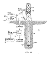
FIG. 1D shows an example of well drilling to obtain core samples. -
FIG. 1E shows an example of a completed wellbore with cemented in place casing having perforations therein in a reservoir formation. -
FIG. 1A shows a side view of anexample test core 110 made of a rock formation known as Berea sandstone as discussed in the Background section herein. Thetest core 110 may be prepared according to the test procedure API RP43 referred to in the Background section herein. While test procedure API RP43 specifies Berea sandstone, the present invention is equally applicable to testing of other rock formations.FIG. 1B shows thetest core 110 after detonation of a shaped charge in a test performed, for example, according to RP43. Aperforation tunnel 112 is created by the action of the shaped charge upon detonation. Operation of shaped charges and how they create perforation tunnels is explained, in a non-limiting example, inU.S. Patent No. 5,567,906 issued to Reese et al . An end view of thecore sample 110 is shown inFIG. 1C to illustrate azone 114 that occupies a roughly annular volume surrounding theperforation tunnel 112 in which the structure of the rock formation is altered to some extent by the action of the "jet" created by the shaped charge detonation. Such alteration within thezone 114 may also affect the fluid transport properties of the rock formation. - An example of drilling a wellbore to obtain samples of rock formations for evaluation by examples of a method according to the invention will be explained with reference to
FIG. 1D . A drilling unit or "rig" 10 is disposed at the Earth's surface. Therig 10 includes lifting equipment (not shown separately) for raising and lowering one of several types of device used to rotate adrill string 14. The device, shown at 18 in the present example may be a top drive, although the use of a top drive is not a limit on the scope of the invention. Thedrill string 14 is assembled by threadedly coupling segments of drill pipe end to end. Adrill bit 16 is disposed at the lower end of thedrill string 14 and cuts throughsubsurface rock formations 11 to form awellbore 12. During the drilling of thewellbore 12, therig 10 is operated to cause some of the axial load (weight) of thedrill string 14 to be applied to thedrill bit 16. Thetop drive 18 rotates thedrill string 14 and thedrill bit 16 at the lower end thereof. The combination of axial load and rotation causes thedrill bit 16 to cut through theformations 11. - The
rig 10 includes a tank orpit 22 having drilling fluid ("mud") 20 stored therein. Apump 24 lifts themud 20 and discharges it through suitable flow lines 26 so that themud 20 passes through an internal passage in thedrill string 14, whereupon it is discharged through suitable orifices or courses in thedrill bit 16. The dischargedmud 20 cools and lubricates thedrill bit 16 and lifts the cuttings generated by thebit 16 to the Earth's surface. The cuttings and mud thus lifted enter separation and cleaning devices, shown generally at 28 and including, for example, devices known as "degassers" and "shale shakers" to remove the cuttings and contamination from themud 20. The mud after such cleaning is returned to thepit 22 for subsequent use in drilling thewellbore 12. - When the wellbore reaches a depth proximate a particular formation of interest, the
drill bit 16 may be replaced by a core drilling bit (not shown) that may recover a substantially cylindrical core sample of the rock formation of interest. The core sample (110 inFIG. 1A ) may be prepared into one or more perforation test cores shaped as explained with reference toFIGS. 1A, 1B and 1C , and perforated according to the conditions specified in RP43. It will be appreciated by those skilled in the art that to use a drilled core sample of the rock formation, it is desirable for the diameter of the core sample to be sufficient to enable perforation testing to be performed in a direction transverse to the axis of the core sample. This is because a drilled core sample is obtained by drilling along the axis of the wellbore, while typical wellbore perforations are made in a direction transverse to the axis of the wellbore. Thus, to simulate how the particular formation will actually be affected by perforation, the directionality of the rock sample with respect to the perforation direction can be important. - In other examples, samples of rock may be obtained from surface outcrops of the formation or near surface deposits of the rock formation. Such samples may be perforation tested in a direction that is expected to be similar to the direction of perforations in a wellbore drilled and cased through such formation. At present, using samples obtained from surface outcrops of rock formations is preferred. It is also known in the art to drill samples of the formation through the wellbore wall transverse to the wellbore axis using a specialized drilling instrument.
-
FIG. 1E shows the wellbore after the drilling operations explained with reference toFIG. 1D have been completed. At the end of the drilling procedure, a steel pipe orcasing 100 may be inserted into thewellbore 12.Cement 102 is then typically pumped through the interior of thecasing 100, whereupon it travels through the bottom end thereof, and into the annular space between the wall of thewellbore 12 and the exterior of thecasing 100. After thecement 102 has sufficiently cured, the remaining components of thewellbore 12 may be installed. In one procedure, anannular sealing element 106 called a packer is inserted into thecasing 100 to a selected depth, typically above a depth of areservoir formation 11A in thesubsurface formations 11. Atubing 108 may be sealingly engaged with thepacker 106, andwellhead equipment 111 may be installed at the top of thecasing 100 andtubing 108. Thewellhead equipment 111 may include control valves and may ultimately be coupled to adischarge conduit 113.Perforations 104 may be made through thecasing 100,cement 102 and into thereservoir formation 11A. Theperforations 104 may be made prior to inserting the packer and tubing using, for example, a casing perforating gun assembly (not shown). Theperforations 104 may alternatively be made with a "tubing conveyed" perforating gun assembly (not shown) that is installed simultaneously with thetubing 108, and actuated, for example by applying fluid pressure to thetubing 108 or dropping an actuation tool (not shown) into thetubing 108. Alternatively, theperforations 104 may be made after insertion of the packer and tubing using a "through tubing" perforating gun assembly. Other methods for creating theperforations 104 are known in the art. The method of the present invention is intended to determine how the creation of theperforations 104 changes one or more petrophysical properties of thereservoir formation 11A, in particular the fluid transport properties. - In the present example, a perforated test core sample (e.g., 110 in
FIG. 1A ) may have taken therefrom small samples of the formation beginning laterally near the perforation tunnel (112 inFIG. 1 ) and continuing successively laterally outwardly. One or more samples may be taken near the lateral edge of the core sample near the back end thereof, where the perforation tunnel may not have caused material effect on the fluid transport properties of the rock formation. Alternatively, samples may be taken from unperforated core (e.g., as 110 inFIG. 1A ). If samples from an unperforated test core are used, a perforation may be created in the test core, and subsequent samples may be taken from the perforated test core for comparative analysis. - The samples may be transported to a computer tomographic ("CT")
scanner 30, which may use x-rays for analysis of internal structure of the cuttings, for generation of three dimensional (3D) images of the test core sample (110 inFIG. 1A ). The images so generated may be in numerical form and their content will be further explained below. After CT scanning, the test cores may be saved for further analysis or may be suitably discarded. - In a practical implementation of core analysis according to the invention, the state of the rock formation prior to perforating can be determined by extracting relatively small portions of the core sample after the test perforating is performed. The state of the rock formation after perforation can be characterized by CT scanning the small samples and estimating fluid transport properties of the foregoing small samples as explained below.
- In an alternative example, a CT image of the entire core may be made using suitable CT imaging devices. The CT image may be made prior to creating the perforation tunnel, and thereafter, or the CT image may be made only after creating the perforation tunnel. The CT image(s) may be segmented into sub images of the entire volume of the core sample similar in volume and position to the physical small samples taken from the entire core sample as explained above.
- The extent to which the rock has been affected by perforating by examination (i.e., CT scan and analysis of the CT scan images thereof) of the small volume samples of the core obtained at progressively greater radial distances from the perforation tunnel axis until the determined fluid transport properties are substantially equal to those of the unaltered rock formation. It is thus possible to quantify the lateral extent of and the magnitude of the formation alteration caused by perforating and to map its radial distribution with respect to the perforation tunnel axis
- CT scan imaging of the test core small samples can be used in the invention to produce a numerical object that represents the material sample digitally in the
computer 32 for subsequent numerical simulations of various physical processes, such as viscous fluid flow (for permeability estimation); stress loading (for the effective elastic moduli); electrical current flow (for resistivity); and pore size distribution for nuclear magnetic resonance relaxation time properties, including distribution of relaxation time. - The CT scan images produced by the CT scanner may be stored or displayed in a computer and can be used as input to one or more rock property characterization models. In the present example, the Lattice-Boltzmann method can be used to numerically solve Navier-Stokes equations for flow simulation. Such solution may be used to calculate permeability of simulated 3D volumes. The Lattice-Boltzmann method is a robust tool for flow simulation, particularly in media with complex pore geometry. See, for example. Ladd, Numerical Simulations of Particulate Suspensions via a discretized Boltzmann Equation, Part 1: Theoretical Foundation, J. Fluid Mech., v271, 1994, pp. 285-309; Gunstensen et al., "Lattice Boltzmann Model of Immiscible Fluids, Phys. Rev. A., v.43, no. 8, Apr. 15, 1991, pp. 4320-4327; Olsen et al., Two-fluid Flow in Sedimentary Rock: Simulation, Transport and Complexity, J. Fluid Mechanics, Vol.341, 1997, pp. 343-370; and Gustensen et al., Lattice-Boltzmann Studies of Immiscible Two-Phase Flow Through Porous Media," J. of Geophysical Research, V.98, No. B4, Apr. 10, 1993, pp. 6431-6441).
- The Lattice-Boltzmann method simulates fluid motion as collisions of imaginary particles, which are much larger than actual fluid molecules, but wherein such particles show almost the same behavior at a macroscopic scale. The algorithm used in the Lattice-Boltzmann method repeats collisions of these imaginary particles until steady state is reached, and provides a distribution of local mass flux. In accordance with the present invention, the Lattice-Boltzmann method is applied successfully for many pore structures, including cylindrical tubes, random densely packed spheres, and 3D rock samples digitized by CT scanning as explained above. See, for example,
U.S. Patent No. 6,516,080 issued to Nur . - It is also possible to estimate capillary pressure related flow characteristics from the pore structure determined using the 3D images processed as explained above. See, for example,
U.S. Patent No. 7,277,795 issued to Boitnott . Other properties of the rock formation that may be modeled include, without limitation, electrical formation resistivity factor, and compressional-wave and shear-wave acoustic velocity. Any or all of the foregoing estimated physical properties may be stored and/or displayed in the computer (32 inFIG. 1 ). - In a particular application of the foregoing technique for analyzing perforation test core samples, the fluid transport properties determined above on perforated core samples (e.g.,
FIG. 1B ) of a formation of interest can be input into conventional reservoir simulator computer programs to derive an estimate of expected fluid production from the wellbore. In a particular application of the foregoing technique, the foregoing image and fluid transport property determination may be made on an unaltered test core sample (FIG. 1A ), and/or as explained above on a portion of the perforated test core obtained sufficiently distant from the perforation tunnel so as to have essentially unaltered petrophysical properties. A shaped charge may then be detonated to create a perforation tunnel (FIG. 1B ). The imaging and fluid transport property determination may then be repeated on small samples of the perforated test core at successively larger radial distances from the perforation tunnel axis as explained above. - Once a reservoir model is developed using the segmented images of the perforated test core, a number of other applications that use the images become possible, such as predicting changes in rock formation flow capacity resulting from changes in relative permeability. Relative permeability may change due to water invasion or gas coning, chemical or other stimulation, re-perforating the casing in a selected formation or blockage of existing perforations in the wellbore
- Methods according to the invention also can enable shaped charge manufacturers to determine how changes in shaped charge explosive type and weight, geometry, and materials affect the flow properties of various rock formations in addition to those commonly used for testing and QC purposes. The topology of the perforation tunnel can be mapped in detail using the segmented images The thickness of the damaged zone (114 in
FIG. 1C ) can be measured and quantified in terms of grain sizes and distribution compared to the unaffected portion of the core sample. Location of metal debris from the shaped charge jet in the perforation tunnel (112 inFIG. 1B ) is also facilitated. - End users (operators) can develop specialized techniques for the use of perforating systems during well completion or repair. The amount of pressure differential (underbalance or overbalance), standoff, shot density (numbers of shaped charges used per unit axial length of wellbore casing), and selection of shaped charge type can also be evaluated. Such evaluated may enable optimization of perforating system cost by potentially reducing the number of perforations required and the total amount of explosive used. It may also be possible to optimize perforation techniques in a particular wellbore to compensate for the relative attitude of the formation (the direction of the bedding planes with respect to the wellbore axis).
- While the example implementation herein is described in terms of jet perforating using explosive shaped charges, it should be clearly understood that the process described herein also applies to other methods of creating hydraulic openings in a well casing into a rock formation, including, without limitation, bullet perforating, hydraulic jetting, laser perforating, rotary boring, etc.
- While the invention has been described with respect to a limited number of embodiments, those skilled in the art, having benefit of this disclosure, will appreciate that other embodiments can be devised which do not depart from the scope of the invention as disclosed herein. Accordingly, the scope of the invention should be limited only by the attached claims.
Claims (16)
- A method for determining effects of perforation on a rock formation (11), comprising:creating a perforation tunnel (112) in a sample (110) obtained of a rock formation; at least one of
subdividing the sample (110) into subsamples and making a three dimensional tomographic image of each subsample after, or before and after, the creating of the perforation tunnel (112) in the sample (110), and
making a three dimensional tomographic image of the sample of rock (110) and segmenting the image thereof into sub images of selected subvolumes of the rock formation sample (110) after, or before and after, the creating of the perforation tunnel (112) in the sample (110); and
estimating at least one physical property of the rock formation (11) from each tomographic image. - The method of claim 1 wherein the at least one physical property comprises permeability.
- The method of claim 2 wherein permeability is estimated using the Lattice-Boltzmann approximation.
- The method of claim 1 wherein the at least one physical property comprises electrical resistivity formation factor.
- The method of claim 1 wherein the at least one physical property comprises acoustic compressional velocity.
- The method of claim 1 wherein the at least one physical property comprises acoustic shear velocity.
- The method of claim 1 wherein the sample (110) of the rock formation (11) comprises a drilled core.
- The method of claim 1 wherein the sample (110) of the rock formation (110) comprises a surface outcrop sample.
- The method of claim 1 further comprising determining a topology of the perforation tunnel (112).
- The method of claim 1 further comprising obtaining samples at a plurality of radial distances from an axis of the perforation tunnel (112) and repeating the making an image, segmenting the image and estimating at least one physical property to obtain a radial profile of the at least one physical property.
- The method of claim 10 further comprising entering the radially profiled physical property as input to a reservoir simulation and estimating fluid flow from a subsurface reservoir from the simulation.
- The method of claim 1 wherein the perforation tunnel (112) is created by detonating a shaped explosive charge.
- The method of claim 1 wherein the three dimensional tomographic image is made before and after the creating of the perforation tunnel (112) in the sample (110), and determining formation alteration for at least one physical property of the rock formation (11) by comparative analyzing of the tomographic image made prior to and after creating the perforation tunnel (112).
- The method of claim 1, wherein the sample (110) is obtained from a surface outcrop of the rock formation (110) or near surface deposits of the rock formation (11), and the creating of the perforation tunnel (112) in the sample (110) comprises perforating the sample (110) to form the perforation tunnel (112) in a direction expected to be similar to a direction of perforations (104) made in an analogous wellbore.
- The method of claim 1, wherein said sample is a test core.
- The method of claim 1, wherein said sample is a test core of Berea sandstone.
Applications Claiming Priority (3)
| Application Number | Priority Date | Filing Date | Title |
|---|---|---|---|
| US22765109P | 2009-07-22 | 2009-07-22 | |
| US12/838,746 US8590382B2 (en) | 2009-07-22 | 2010-07-19 | Method for evaluating shaped charge perforation test cores using computer tomographic images thereof |
| PCT/US2010/042803 WO2011011551A1 (en) | 2009-07-22 | 2010-07-21 | Method for evaluating shaped charge perforation test cores using computer tomographic images thereof |
Publications (2)
| Publication Number | Publication Date |
|---|---|
| EP2457082A1 EP2457082A1 (en) | 2012-05-30 |
| EP2457082B1 true EP2457082B1 (en) | 2015-06-03 |
Family
ID=43496275
Family Applications (1)
| Application Number | Title | Priority Date | Filing Date |
|---|---|---|---|
| EP10765702.5A Not-in-force EP2457082B1 (en) | 2009-07-22 | 2010-07-21 | Method for evaluating shaped charge perforation test cores using computer tomographic images thereof |
Country Status (5)
| Country | Link |
|---|---|
| US (1) | US8590382B2 (en) |
| EP (1) | EP2457082B1 (en) |
| AU (1) | AU2010276161B2 (en) |
| BR (1) | BR112012001422B1 (en) |
| WO (1) | WO2011011551A1 (en) |
Cited By (1)
| Publication number | Priority date | Publication date | Assignee | Title |
|---|---|---|---|---|
| CN110082220A (en) * | 2019-05-31 | 2019-08-02 | 重庆大学 | A kind of porous guiding fracturing experiments device of true triaxial |
Families Citing this family (25)
| Publication number | Priority date | Publication date | Assignee | Title |
|---|---|---|---|---|
| WO2013169973A1 (en) * | 2012-05-11 | 2013-11-14 | Ingrain, Inc. | A method and system for multi-energy computer tomographic cuttings analysis |
| RU2014151234A (en) * | 2012-05-18 | 2016-07-10 | Ингрейн, Инк. | METHOD AND SYSTEM FOR EVALUATING ROCK PROPERTIES BASED ON ROCK SAMPLES USING DIGITAL VISUALIZATION OF ROCK PHYSICAL PROPERTIES |
| AU2013323422B2 (en) * | 2012-09-27 | 2018-07-05 | Ingrain, Inc. | Computed tomography (CT) systems and methods analyzing rock property changes resulting from a treatment |
| BR112015009770A2 (en) | 2012-11-01 | 2017-07-11 | Ingrain Inc | rock and other sample characterization by process and system for sample preparation using refractory mounting materials |
| US20150346119A1 (en) * | 2013-03-26 | 2015-12-03 | Halliburton Energy Services, Inc. | Determining Perforation Tunnel Impairment Productivity Using Computed Tomography |
| WO2015084533A1 (en) * | 2013-12-05 | 2015-06-11 | Schlumberger Canada Limited | Digital core model construction |
| US10151677B2 (en) * | 2014-07-08 | 2018-12-11 | Halliburton Energy Services, Inc. | Real-time optical flow imaging to determine particle size distribution |
| BR112017001099A2 (en) * | 2014-07-18 | 2018-01-23 | Geoquest Systems Bv | method for image processing of a non-transient computer readable witness box, system, and media that stores instructions |
| US10001446B2 (en) | 2014-11-07 | 2018-06-19 | Ge Energy Oilfield Technology, Inc. | Core sample analysis |
| US9970888B2 (en) * | 2014-11-07 | 2018-05-15 | Ge Energy Oilfield Technology, Inc. | System and method for wellsite core sample analysis |
| US9880318B2 (en) * | 2014-11-07 | 2018-01-30 | Ge Energy Oilfield Technology, Inc. | Method for analyzing core sample from wellbore, involves analyzing zone of interest in core sample, and forming image of core sample to spatially represent characteristics of core sample |
| BR112017008907A2 (en) | 2014-11-17 | 2017-12-26 | Halliburton Energy Services Inc | method |
| US10031148B2 (en) | 2014-12-31 | 2018-07-24 | Ge Energy Oilfield Technology, Inc. | System for handling a core sample |
| US10261204B2 (en) | 2014-12-31 | 2019-04-16 | Ge Energy Oilfield Technology, Inc. | Methods and systems for scan analysis of a core sample |
| US11460256B2 (en) * | 2016-06-23 | 2022-10-04 | Modine Manufacturing Company | Heat exchanger header |
| US11585646B2 (en) * | 2018-11-27 | 2023-02-21 | Halliburton Energy Services, Inc. | Shaped charge effect measurement |
| WO2020167297A1 (en) | 2019-02-12 | 2020-08-20 | Halliburton Energy Services, Inc. | Managing wellbore cement compositions based on material characteristics |
| CN110987985A (en) * | 2019-12-27 | 2020-04-10 | 西南石油大学 | Method for evaluating digital core in perforation damage chamber |
| US11846183B2 (en) | 2020-02-11 | 2023-12-19 | Halliburton Energy Services, Inc. | Determination of perforation crush zone permeability |
| CN112595835A (en) * | 2020-12-03 | 2021-04-02 | 西南交通大学 | Geological bedding tunnel model test device and test method thereof |
| CN112539050B (en) * | 2021-01-21 | 2021-05-25 | 东北石油大学 | Combined 3D spiral perforation simulated injection device and simulation method |
| CN115522920B (en) * | 2022-11-24 | 2023-02-10 | 西南石油大学 | A test device for measuring gas-water double-layer perforation production of tight sandstone gas reservoirs |
| US12084958B2 (en) | 2023-01-04 | 2024-09-10 | Saudi Arabian Oil Company | Systems and methods for determining rock strengths |
| CN116907362B (en) * | 2023-05-10 | 2025-02-11 | 重庆大学 | A method for determining the safe thickness of a tunnel in a deep, water-rich fault zone and its test assembly |
| CN116482336B (en) * | 2023-06-26 | 2023-08-22 | 中海油田服务股份有限公司 | Multi-dimensional perforation damage evaluation method, device, computing equipment and storage medium |
Family Cites Families (7)
| Publication number | Priority date | Publication date | Assignee | Title |
|---|---|---|---|---|
| US5460095A (en) | 1994-12-29 | 1995-10-24 | Western Atlas International, Inc. | Mounting apparatus for expendable bar carrier shaped-charges |
| US5567906B1 (en) | 1995-05-15 | 1998-06-09 | Western Atlas Int Inc | Tungsten enhanced liner for a shaped charge |
| US6003620A (en) * | 1996-07-26 | 1999-12-21 | Advanced Coring Technology, Inc. | Downhole in-situ measurement of physical and or chemical properties including fluid saturations of cores while coring |
| US6516080B1 (en) | 2000-04-05 | 2003-02-04 | The Board Of Trustees Of The Leland Stanford Junior University | Numerical method of estimating physical properties of three-dimensional porous media |
| RU2213852C2 (en) | 2001-12-18 | 2003-10-10 | Общество с ограниченной ответственностью "Научно-исследовательский центр "ГЕОМЕХАНИКА и ТЕХНОЛОГИЯ" | Method of injection well treatment |
| US7277795B2 (en) | 2004-04-07 | 2007-10-02 | New England Research, Inc. | Method for estimating pore structure of porous materials and its application to determining physical properties of the materials |
| US7620534B2 (en) * | 2006-04-28 | 2009-11-17 | Saudi Aramco | Sound enabling computerized system for real time reservoir model calibration using field surveillance data |
-
2010
- 2010-07-19 US US12/838,746 patent/US8590382B2/en active Active
- 2010-07-21 EP EP10765702.5A patent/EP2457082B1/en not_active Not-in-force
- 2010-07-21 WO PCT/US2010/042803 patent/WO2011011551A1/en not_active Ceased
- 2010-07-21 AU AU2010276161A patent/AU2010276161B2/en not_active Ceased
- 2010-07-21 BR BR112012001422-6A patent/BR112012001422B1/en active IP Right Grant
Cited By (1)
| Publication number | Priority date | Publication date | Assignee | Title |
|---|---|---|---|---|
| CN110082220A (en) * | 2019-05-31 | 2019-08-02 | 重庆大学 | A kind of porous guiding fracturing experiments device of true triaxial |
Also Published As
| Publication number | Publication date |
|---|---|
| EP2457082A1 (en) | 2012-05-30 |
| BR112012001422A2 (en) | 2020-08-11 |
| BR112012001422B1 (en) | 2021-11-16 |
| AU2010276161B2 (en) | 2013-11-28 |
| WO2011011551A1 (en) | 2011-01-27 |
| AU2010276161A1 (en) | 2012-02-16 |
| US20110017447A1 (en) | 2011-01-27 |
| US8590382B2 (en) | 2013-11-26 |
Similar Documents
| Publication | Publication Date | Title |
|---|---|---|
| AU2010276161B2 (en) | Method for evaluating shaped charge perforation test cores using computer tomographic images thereof | |
| US9507047B1 (en) | Method and system for integrating logging tool data and digital rock physics to estimate rock formation properties | |
| WO2014032003A1 (en) | System and method for performing stimulation operations | |
| WO2016100762A1 (en) | Workflows to address localized stress regime heterogeneity to enable hydraulic fracturing | |
| WO2012090174A2 (en) | System and method for performing downhole stimulation operations | |
| EP3077618A1 (en) | Tuning digital core analysis to laboratory results | |
| WO2017003840A1 (en) | Method of performing additional oilfield operations on existing wells | |
| WO2017027342A1 (en) | Method of performing complex fracture operations at a wellsite having ledged fractures | |
| US10337294B2 (en) | Reservoir permeability upscaling | |
| US20250198901A1 (en) | System and method for determining the fluid flow with tracer in fractured rock sample | |
| US20250138219A1 (en) | Determination of 3d minimum horizontal stress for naturally fractured reservoirs | |
| US9482088B2 (en) | Mean regression function for permeability | |
| Qiu et al. | Sand Production Prediction and Safe Differential Pressure Determination in a Deepwater Gas Field. | |
| WO2015094307A1 (en) | Pore size classification in subterranean formations based on nuclear magnetic resonance (nmr) relaxation distributions | |
| US20240053245A1 (en) | Determining relative permeability in a rock sample | |
| Wang et al. | Development of in-situ permeability testing system for low-permeability sandstone-type uranium deposits | |
| AU2017202319A1 (en) | System and method for performing downhole stimulation operations | |
| US20240191621A1 (en) | Method and system for determining high permeability zones within a reservoir using weathering index data | |
| EP3821107A1 (en) | Systems and methods to identify and inhibit spider web borehole failure in hydrocarbon wells | |
| EP4211335B1 (en) | Geologic formation characterization | |
| US11940398B2 (en) | Method to determine relative thermal maturity from porosities measured by quantitative imaging on uncleaned samples and GRI porosity measured on crushed cleaned samples | |
| US20250122796A1 (en) | Method for deep well testing and permeability determination in different directions | |
| Nurhandoko et al. | Thick Walled Core Testing for Sanding Analysis of Chalky Carbonate Reservoir in Production Borehole | |
| US10460051B2 (en) | Computationally-efficient modeling of viscous fingering effect for enhanced oil recovery (EOR) agent injected at multiple injection concentrations | |
| Birkholzer et al. | A new modeling framework for multi-scale simulation of hydraulic fracturing and |
Legal Events
| Date | Code | Title | Description |
|---|---|---|---|
| PUAI | Public reference made under article 153(3) epc to a published international application that has entered the european phase |
Free format text: ORIGINAL CODE: 0009012 |
|
| 17P | Request for examination filed |
Effective date: 20120111 |
|
| AK | Designated contracting states |
Kind code of ref document: A1 Designated state(s): AL AT BE BG CH CY CZ DE DK EE ES FI FR GB GR HR HU IE IS IT LI LT LU LV MC MK MT NL NO PL PT RO SE SI SK SM TR |
|
| DAX | Request for extension of the european patent (deleted) | ||
| REG | Reference to a national code |
Ref country code: DE Ref legal event code: R079 Ref document number: 602010025078 Country of ref document: DE Free format text: PREVIOUS MAIN CLASS: G01N0023040000 Ipc: E21B0043119000 |
|
| RIC1 | Information provided on ipc code assigned before grant |
Ipc: E21B 43/119 20060101AFI20141208BHEP Ipc: G01N 23/04 20060101ALI20141208BHEP Ipc: E21B 49/00 20060101ALI20141208BHEP |
|
| GRAP | Despatch of communication of intention to grant a patent |
Free format text: ORIGINAL CODE: EPIDOSNIGR1 |
|
| INTG | Intention to grant announced |
Effective date: 20150129 |
|
| GRAS | Grant fee paid |
Free format text: ORIGINAL CODE: EPIDOSNIGR3 |
|
| GRAA | (expected) grant |
Free format text: ORIGINAL CODE: 0009210 |
|
| AK | Designated contracting states |
Kind code of ref document: B1 Designated state(s): AL AT BE BG CH CY CZ DE DK EE ES FI FR GB GR HR HU IE IS IT LI LT LU LV MC MK MT NL NO PL PT RO SE SI SK SM TR |
|
| REG | Reference to a national code |
Ref country code: GB Ref legal event code: FG4D |
|
| REG | Reference to a national code |
Ref country code: CH Ref legal event code: EP |
|
| REG | Reference to a national code |
Ref country code: AT Ref legal event code: REF Ref document number: 730040 Country of ref document: AT Kind code of ref document: T Effective date: 20150715 Ref country code: IE Ref legal event code: FG4D |
|
| REG | Reference to a national code |
Ref country code: DE Country of ref document: DE Effective date: 20150716 Ref legal event code: R096 Ref document number: 602010025078 |
|
| REG | Reference to a national code |
Ref country code: AT Ref legal event code: MK05 Ref document number: 730040 Country of ref document: AT Kind code of ref document: T Effective date: 20150603 |
|
| PG25 | Lapsed in a contracting state [announced via postgrant information from national office to epo] |
Ref country code: NO Free format text: LAPSE BECAUSE OF FAILURE TO SUBMIT A TRANSLATION OF THE DESCRIPTION OR TO PAY THE FEE WITHIN THE PRESCRIBED TIME-LIMIT Effective date: 20150903 Ref country code: LT Free format text: LAPSE BECAUSE OF FAILURE TO SUBMIT A TRANSLATION OF THE DESCRIPTION OR TO PAY THE FEE WITHIN THE PRESCRIBED TIME-LIMIT Effective date: 20150603 Ref country code: FI Free format text: LAPSE BECAUSE OF FAILURE TO SUBMIT A TRANSLATION OF THE DESCRIPTION OR TO PAY THE FEE WITHIN THE PRESCRIBED TIME-LIMIT Effective date: 20150603 Ref country code: ES Free format text: LAPSE BECAUSE OF FAILURE TO SUBMIT A TRANSLATION OF THE DESCRIPTION OR TO PAY THE FEE WITHIN THE PRESCRIBED TIME-LIMIT Effective date: 20150603 Ref country code: HR Free format text: LAPSE BECAUSE OF FAILURE TO SUBMIT A TRANSLATION OF THE DESCRIPTION OR TO PAY THE FEE WITHIN THE PRESCRIBED TIME-LIMIT Effective date: 20150603 |
|
| REG | Reference to a national code |
Ref country code: NL Ref legal event code: MP Effective date: 20150603 |
|
| REG | Reference to a national code |
Ref country code: LT Ref legal event code: MG4D |
|
| PG25 | Lapsed in a contracting state [announced via postgrant information from national office to epo] |
Ref country code: LV Free format text: LAPSE BECAUSE OF FAILURE TO SUBMIT A TRANSLATION OF THE DESCRIPTION OR TO PAY THE FEE WITHIN THE PRESCRIBED TIME-LIMIT Effective date: 20150603 Ref country code: AT Free format text: LAPSE BECAUSE OF FAILURE TO SUBMIT A TRANSLATION OF THE DESCRIPTION OR TO PAY THE FEE WITHIN THE PRESCRIBED TIME-LIMIT Effective date: 20150603 Ref country code: BG Free format text: LAPSE BECAUSE OF FAILURE TO SUBMIT A TRANSLATION OF THE DESCRIPTION OR TO PAY THE FEE WITHIN THE PRESCRIBED TIME-LIMIT Effective date: 20150903 Ref country code: GR Free format text: LAPSE BECAUSE OF FAILURE TO SUBMIT A TRANSLATION OF THE DESCRIPTION OR TO PAY THE FEE WITHIN THE PRESCRIBED TIME-LIMIT Effective date: 20150904 |
|
| PG25 | Lapsed in a contracting state [announced via postgrant information from national office to epo] |
Ref country code: EE Free format text: LAPSE BECAUSE OF FAILURE TO SUBMIT A TRANSLATION OF THE DESCRIPTION OR TO PAY THE FEE WITHIN THE PRESCRIBED TIME-LIMIT Effective date: 20150603 |
|
| PG25 | Lapsed in a contracting state [announced via postgrant information from national office to epo] |
Ref country code: RO Free format text: LAPSE BECAUSE OF NON-PAYMENT OF DUE FEES Effective date: 20150603 Ref country code: CZ Free format text: LAPSE BECAUSE OF FAILURE TO SUBMIT A TRANSLATION OF THE DESCRIPTION OR TO PAY THE FEE WITHIN THE PRESCRIBED TIME-LIMIT Effective date: 20150603 Ref country code: SK Free format text: LAPSE BECAUSE OF FAILURE TO SUBMIT A TRANSLATION OF THE DESCRIPTION OR TO PAY THE FEE WITHIN THE PRESCRIBED TIME-LIMIT Effective date: 20150603 Ref country code: PL Free format text: LAPSE BECAUSE OF FAILURE TO SUBMIT A TRANSLATION OF THE DESCRIPTION OR TO PAY THE FEE WITHIN THE PRESCRIBED TIME-LIMIT Effective date: 20150603 Ref country code: IS Free format text: LAPSE BECAUSE OF FAILURE TO SUBMIT A TRANSLATION OF THE DESCRIPTION OR TO PAY THE FEE WITHIN THE PRESCRIBED TIME-LIMIT Effective date: 20151003 Ref country code: PT Free format text: LAPSE BECAUSE OF FAILURE TO SUBMIT A TRANSLATION OF THE DESCRIPTION OR TO PAY THE FEE WITHIN THE PRESCRIBED TIME-LIMIT Effective date: 20151006 |
|
| REG | Reference to a national code |
Ref country code: CH Ref legal event code: PL |
|
| REG | Reference to a national code |
Ref country code: DE Ref legal event code: R097 Ref document number: 602010025078 Country of ref document: DE |
|
| PG25 | Lapsed in a contracting state [announced via postgrant information from national office to epo] |
Ref country code: MC Free format text: LAPSE BECAUSE OF FAILURE TO SUBMIT A TRANSLATION OF THE DESCRIPTION OR TO PAY THE FEE WITHIN THE PRESCRIBED TIME-LIMIT Effective date: 20150603 |
|
| PLBE | No opposition filed within time limit |
Free format text: ORIGINAL CODE: 0009261 |
|
| STAA | Information on the status of an ep patent application or granted ep patent |
Free format text: STATUS: NO OPPOSITION FILED WITHIN TIME LIMIT |
|
| REG | Reference to a national code |
Ref country code: IE Ref legal event code: MM4A |
|
| PG25 | Lapsed in a contracting state [announced via postgrant information from national office to epo] |
Ref country code: LI Free format text: LAPSE BECAUSE OF NON-PAYMENT OF DUE FEES Effective date: 20150731 Ref country code: CH Free format text: LAPSE BECAUSE OF NON-PAYMENT OF DUE FEES Effective date: 20150731 Ref country code: IT Free format text: LAPSE BECAUSE OF FAILURE TO SUBMIT A TRANSLATION OF THE DESCRIPTION OR TO PAY THE FEE WITHIN THE PRESCRIBED TIME-LIMIT Effective date: 20150603 Ref country code: DK Free format text: LAPSE BECAUSE OF FAILURE TO SUBMIT A TRANSLATION OF THE DESCRIPTION OR TO PAY THE FEE WITHIN THE PRESCRIBED TIME-LIMIT Effective date: 20150603 |
|
| 26N | No opposition filed |
Effective date: 20160304 |
|
| GBPC | Gb: european patent ceased through non-payment of renewal fee |
Effective date: 20150903 |
|
| PG25 | Lapsed in a contracting state [announced via postgrant information from national office to epo] |
Ref country code: SI Free format text: LAPSE BECAUSE OF FAILURE TO SUBMIT A TRANSLATION OF THE DESCRIPTION OR TO PAY THE FEE WITHIN THE PRESCRIBED TIME-LIMIT Effective date: 20150603 |
|
| REG | Reference to a national code |
Ref country code: FR Ref legal event code: PLFP Year of fee payment: 7 |
|
| PG25 | Lapsed in a contracting state [announced via postgrant information from national office to epo] |
Ref country code: GB Free format text: LAPSE BECAUSE OF NON-PAYMENT OF DUE FEES Effective date: 20150903 Ref country code: IE Free format text: LAPSE BECAUSE OF NON-PAYMENT OF DUE FEES Effective date: 20150721 |
|
| PG25 | Lapsed in a contracting state [announced via postgrant information from national office to epo] |
Ref country code: BE Free format text: LAPSE BECAUSE OF FAILURE TO SUBMIT A TRANSLATION OF THE DESCRIPTION OR TO PAY THE FEE WITHIN THE PRESCRIBED TIME-LIMIT Effective date: 20150603 |
|
| PG25 | Lapsed in a contracting state [announced via postgrant information from national office to epo] |
Ref country code: MT Free format text: LAPSE BECAUSE OF FAILURE TO SUBMIT A TRANSLATION OF THE DESCRIPTION OR TO PAY THE FEE WITHIN THE PRESCRIBED TIME-LIMIT Effective date: 20150603 |
|
| PG25 | Lapsed in a contracting state [announced via postgrant information from national office to epo] |
Ref country code: HU Free format text: LAPSE BECAUSE OF FAILURE TO SUBMIT A TRANSLATION OF THE DESCRIPTION OR TO PAY THE FEE WITHIN THE PRESCRIBED TIME-LIMIT; INVALID AB INITIO Effective date: 20100721 Ref country code: SM Free format text: LAPSE BECAUSE OF FAILURE TO SUBMIT A TRANSLATION OF THE DESCRIPTION OR TO PAY THE FEE WITHIN THE PRESCRIBED TIME-LIMIT Effective date: 20150603 |
|
| PG25 | Lapsed in a contracting state [announced via postgrant information from national office to epo] |
Ref country code: SE Free format text: LAPSE BECAUSE OF FAILURE TO SUBMIT A TRANSLATION OF THE DESCRIPTION OR TO PAY THE FEE WITHIN THE PRESCRIBED TIME-LIMIT Effective date: 20150603 Ref country code: CY Free format text: LAPSE BECAUSE OF FAILURE TO SUBMIT A TRANSLATION OF THE DESCRIPTION OR TO PAY THE FEE WITHIN THE PRESCRIBED TIME-LIMIT Effective date: 20150603 Ref country code: NL Free format text: LAPSE BECAUSE OF FAILURE TO SUBMIT A TRANSLATION OF THE DESCRIPTION OR TO PAY THE FEE WITHIN THE PRESCRIBED TIME-LIMIT Effective date: 20150603 |
|
| REG | Reference to a national code |
Ref country code: FR Ref legal event code: PLFP Year of fee payment: 8 |
|
| PG25 | Lapsed in a contracting state [announced via postgrant information from national office to epo] |
Ref country code: TR Free format text: LAPSE BECAUSE OF FAILURE TO SUBMIT A TRANSLATION OF THE DESCRIPTION OR TO PAY THE FEE WITHIN THE PRESCRIBED TIME-LIMIT Effective date: 20150603 |
|
| PG25 | Lapsed in a contracting state [announced via postgrant information from national office to epo] |
Ref country code: LU Free format text: LAPSE BECAUSE OF NON-PAYMENT OF DUE FEES Effective date: 20150721 |
|
| REG | Reference to a national code |
Ref country code: DE Ref legal event code: R082 Ref document number: 602010025078 Country of ref document: DE Representative=s name: WITHERS & ROGERS LLP, DE Ref country code: DE Ref legal event code: R082 Ref document number: 602010025078 Country of ref document: DE Representative=s name: FLEUCHAUS & GALLO PARTNERSCHAFT MBB, DE |
|
| PG25 | Lapsed in a contracting state [announced via postgrant information from national office to epo] |
Ref country code: MK Free format text: LAPSE BECAUSE OF FAILURE TO SUBMIT A TRANSLATION OF THE DESCRIPTION OR TO PAY THE FEE WITHIN THE PRESCRIBED TIME-LIMIT Effective date: 20150603 |
|
| REG | Reference to a national code |
Ref country code: FR Ref legal event code: PLFP Year of fee payment: 9 |
|
| PG25 | Lapsed in a contracting state [announced via postgrant information from national office to epo] |
Ref country code: AL Free format text: LAPSE BECAUSE OF FAILURE TO SUBMIT A TRANSLATION OF THE DESCRIPTION OR TO PAY THE FEE WITHIN THE PRESCRIBED TIME-LIMIT Effective date: 20150603 |
|
| REG | Reference to a national code |
Ref country code: DE Ref legal event code: R082 Ref document number: 602010025078 Country of ref document: DE Representative=s name: WITHERS & ROGERS LLP, DE |
|
| PGFP | Annual fee paid to national office [announced via postgrant information from national office to epo] |
Ref country code: FR Payment date: 20190730 Year of fee payment: 10 Ref country code: DE Payment date: 20190730 Year of fee payment: 10 |
|
| REG | Reference to a national code |
Ref country code: DE Ref legal event code: R119 Ref document number: 602010025078 Country of ref document: DE |
|
| PG25 | Lapsed in a contracting state [announced via postgrant information from national office to epo] |
Ref country code: FR Free format text: LAPSE BECAUSE OF NON-PAYMENT OF DUE FEES Effective date: 20200731 |
|
| PG25 | Lapsed in a contracting state [announced via postgrant information from national office to epo] |
Ref country code: DE Free format text: LAPSE BECAUSE OF NON-PAYMENT OF DUE FEES Effective date: 20210202 |