EP2456498B1 - A balloon for catheters - Google Patents
A balloon for catheters Download PDFInfo
- Publication number
- EP2456498B1 EP2456498B1 EP10752184.1A EP10752184A EP2456498B1 EP 2456498 B1 EP2456498 B1 EP 2456498B1 EP 10752184 A EP10752184 A EP 10752184A EP 2456498 B1 EP2456498 B1 EP 2456498B1
- Authority
- EP
- European Patent Office
- Prior art keywords
- balloon
- obturators
- passageways
- wall portion
- liquid
- Prior art date
- Legal status (The legal status is an assumption and is not a legal conclusion. Google has not performed a legal analysis and makes no representation as to the accuracy of the status listed.)
- Active
Links
Images



Classifications
-
- A—HUMAN NECESSITIES
- A61—MEDICAL OR VETERINARY SCIENCE; HYGIENE
- A61M—DEVICES FOR INTRODUCING MEDIA INTO, OR ONTO, THE BODY; DEVICES FOR TRANSDUCING BODY MEDIA OR FOR TAKING MEDIA FROM THE BODY; DEVICES FOR PRODUCING OR ENDING SLEEP OR STUPOR
- A61M25/00—Catheters; Hollow probes
- A61M25/10—Balloon catheters
- A61M25/1027—Making of balloon catheters
- A61M25/1029—Production methods of the balloon members, e.g. blow-moulding, extruding, deposition or by wrapping a plurality of layers of balloon material around a mandril
-
- A—HUMAN NECESSITIES
- A61—MEDICAL OR VETERINARY SCIENCE; HYGIENE
- A61M—DEVICES FOR INTRODUCING MEDIA INTO, OR ONTO, THE BODY; DEVICES FOR TRANSDUCING BODY MEDIA OR FOR TAKING MEDIA FROM THE BODY; DEVICES FOR PRODUCING OR ENDING SLEEP OR STUPOR
- A61M25/00—Catheters; Hollow probes
- A61M25/10—Balloon catheters
-
- A—HUMAN NECESSITIES
- A61—MEDICAL OR VETERINARY SCIENCE; HYGIENE
- A61M—DEVICES FOR INTRODUCING MEDIA INTO, OR ONTO, THE BODY; DEVICES FOR TRANSDUCING BODY MEDIA OR FOR TAKING MEDIA FROM THE BODY; DEVICES FOR PRODUCING OR ENDING SLEEP OR STUPOR
- A61M25/00—Catheters; Hollow probes
- A61M25/10—Balloon catheters
- A61M2025/1043—Balloon catheters with special features or adapted for special applications
- A61M2025/105—Balloon catheters with special features or adapted for special applications having a balloon suitable for drug delivery, e.g. by using holes for delivery, drug coating or membranes
-
- A—HUMAN NECESSITIES
- A61—MEDICAL OR VETERINARY SCIENCE; HYGIENE
- A61M—DEVICES FOR INTRODUCING MEDIA INTO, OR ONTO, THE BODY; DEVICES FOR TRANSDUCING BODY MEDIA OR FOR TAKING MEDIA FROM THE BODY; DEVICES FOR PRODUCING OR ENDING SLEEP OR STUPOR
- A61M25/00—Catheters; Hollow probes
- A61M25/10—Balloon catheters
- A61M2025/1043—Balloon catheters with special features or adapted for special applications
- A61M2025/1075—Balloon catheters with special features or adapted for special applications having a balloon composed of several layers, e.g. by coating or embedding
-
- A—HUMAN NECESSITIES
- A61—MEDICAL OR VETERINARY SCIENCE; HYGIENE
- A61M—DEVICES FOR INTRODUCING MEDIA INTO, OR ONTO, THE BODY; DEVICES FOR TRANSDUCING BODY MEDIA OR FOR TAKING MEDIA FROM THE BODY; DEVICES FOR PRODUCING OR ENDING SLEEP OR STUPOR
- A61M25/00—Catheters; Hollow probes
- A61M25/10—Balloon catheters
- A61M2025/1043—Balloon catheters with special features or adapted for special applications
- A61M2025/1086—Balloon catheters with special features or adapted for special applications having a special balloon surface topography, e.g. pores, protuberances, spikes or grooves
Definitions
- the present disclosure relates to balloons for catheters.
- the present disclosure has been developed with particular attention paid to its possible application to angioplasty (with or without the use of stents) of blood vessels, such as for example the coronary arteries or peripheral vessels of various nature.
- PTA percutaneous transluminal angioplasty
- stents of the "drug-eluting" type that are able to release an active agent, such as for example an agent antagonistic to restenosis, on the site treated.
- the typical diameter of the pre-formed openings that can be obtained with known manufacturing methods is in the vicinity of a few micrometres, at times just a little more than ten micrometres, which renders impracticable the installation of any accessory element, in view, above all, also of the non-negligible deformation that the balloon undergoes.
- an active agent such as an agent antagonistic to restenosis in the framework of an angioplasty treatment (with or without the application of a stent, possibly of the drug-eluting type), it is desirable to prevent as much as possible that:
- the object of the present invention is to provide a balloon that is able to meet the requirements outlined above.
- the description also provides a corresponding manufacturing method.
- the reference number 10 designates as a whole a balloon of a balloon catheter used for an angioplasty treatment (PTA) of a vessel V.
- PTA angioplasty treatment
- the balloon 10 is mounted at the distal end of an introduction catheter C intended to allow the introduction of the balloon 10 in a radially contracted condition, usually folded, into the body of the patient in view of its positioning, performed via catheterism (for example, resorting to a guide wire GW), in a site of a vessel V that is to be treated.
- the vessel in question may, for example, be one of the coronary arteries.
- the balloon 10 may be dilated so as to assume the condition schematically represented in Figure 1 by supplying inside it an inflation fluid that is made to flow through the stem of the catheter C.
- the fluid in question may be a liquid (for example, a physiological solution) pressurized by means of a syringe S actuated by an operator who introduces the pressurized liquid into the proximal end of the catheter C.
- a liquid for example, a physiological solution
- the balloon 10 is provided with an openwork or porous region, designated by 12, so as to enable an active agent (for example an agent antagonistic to restenosis) conveyed by the pressurized liquid that causes the expansion of the balloon 10 to be diffused in the wall of the vessel V.
- an active agent for example an agent antagonistic to restenosis
- FIG. 2 The cross-sectional view of Figure 2 highlights the fact that, in correspondence of the area 12, the wall 14 of the balloon 10 (here represented in an expanded condition) is provided with openings - i.e., passageways - 16, which have the characteristics that may be more readily appreciated with reference to Figures 3 to 6 .
- the passageways 16 are basically configured as holes in which an obturator (in practice a septum) 18 is present, located for example in an end position, for instance at the radially internal end with respect to the development of the balloon 10.
- the inventive obturator 18 presents, also according to the manufacturing process, a shape at least slightly lenticular and plano-convex with the convexity facing the outside of the balloon 10.
- the holes 16 initially present in the form of blind holes.
- the blind hole condition of the openings 16 is maintained when the inflation liquid that conveyes the active agent is initially made to flow within the balloon 10 and also during the initial step of expansion of the balloon 10, which is obtained at a pressure practically equal to the atmospheric pressure until the wall 14 of the balloon 10 comes into contact with the wall of the vessel V undergoing treatment (see, for example, the condition illustrated in Figure 1 ) .
- the openings or passageways 16 are blind holes prevents the active agent from being dispersed in an undesirable way.
- the vessel V itself starts to offer resistance to the further expansion of the balloon 10, and the pumping action of the syringe S (which may possibly be a motor-driven syringe) induces in the inflation fluid the increase in pressure that underlies the angioplasty treatment, which basically amounts to an action (or more correctly, to a repeated sequence of actions) of forced dilation of the vessel V.
- the syringe S which may possibly be a motor-driven syringe
- the obturator 18 is intrinsically "thin" with respect to the overall thickness of the wall 14.
- the wall 14 can have a thickness (measured in a radial direction with respect to the balloon 10) in the region of 10 to 50 ⁇ m-i.e., 10 to 50 x 10 -6 metres - and the obturator 18 can have (also according to the materials used) a thickness from 10% to 50 % of the thickness of the wall 14.
- the increase in pressure of the inflation liquid has the effect of deforming, i.e., bulging, the obturator 18 (in the embodiment illustrated, in which the obturator 18 is located at the internal end of the hole 16, there is an introflection within the hole itself) until the condition is reached in which, on account of its gradual bulging, the obturator forms a sort of bubble that explodes ( Figure 5 ) creating an opening 180.
- the burst of the obturators 18 may occur at a pressure from 2 to 10 bar higher than the nominal operating pressure of the balloon 10, hence remaining in safety conditions below the rated burst pressure (RBP) of the balloon 10.
- the hole 16 is rendered pervious, and the inflation liquid L is able to flow towards the wall of the vessel V so as to produce the desired action of diffusion of the active agent conveyed thereby.
- the angioplasty treatment can envisage an alternating sequence of expansions and contractions of the balloon 10 obtained by varying correspondingly (i.e., by increasing and decreasing) the pressure of the inflation liquid L.
- the decrease in pressure of the inflation liquid leads to detachment of the wall of the balloon 14 from the wall of the vessel V: the action of deflation is in fact designed to enable flow of the blood within the treated vessel, which would be otherwise occluded by the balloon 10 when the balloon 10 itself is in the dilated condition.
- the modalities of formation of the opening 180 obtained by bursting a "bubble" created as a result of the deformation of the material forming the obturator 18 (which may be a material such as polyamide, e.g., Nylon 12) means that, when the pressure of the inflation liquid within the balloon 10 drops, the obturator 18 behaves as a whole more or less like the leaflets of a cardiac valve when the direction of the blood through the valve reverses with respect to the direction of free flow.
- the material forming the obturator 18 which may be a material such as polyamide, e.g., Nylon 12
- the obturator 18 tends to return approximately to the original condition so that the opening 180 is in effect choked (see once again Figure 6 ).
- the deformation of the material such as to lead to the formation of the "bubble", which then bursts giving rise to the opening 180, can in fact bring about a certain stretching of the material constituting the obturator.
- the holes 16 may have a diameter of less than 20 ⁇ m (20 x 10 -6 metres) .
- inventive obturators 18 are formed as convex frangible septa with the convexity facing the outside of the balloon 10.
- a septum which is convex towards the outside of the balloon 10 may exert a strong sealing action when the pressure of the inflation liquid within the balloon decreases, because possible flaps of the septum 18 created following upon burst thereof have a shape slightly arched outwards, which allows to reclose the aperture 180 with an action at least roughly assimilable to the action of the valve leaflets of a valve such as a heart valve.
- a balloon 10 according to the embodiments considered herein can be obtained with various techniques.
- the wall 14 could be produced in the form of a double-layer structure with a thin internal tubular layer designed to constitute the obturators 18 fitted on which is a perforated tubular tunic, whose perforations or pores constitute the open part of the holes 16.
- the relative arrangement can even be reversed, with the thin layer set on the outside of the perforated tunic, in which case the obturators 18 are located at the outer end of the openings 16 (in Figures 3 to 6 the obturators 18 are instead located at the inner end).
- Figures 7 to 11 refer to an example of a method for producing a balloon 10 by resorting to a technique that can be substantially defined as a dipping technique, which can be used, for example, for producing balloons 10 with a base of a silicone material.
- the reference 100 designates a core (in practice a rod) having diametral dimensions that, in one example, substantially correspond to the desired diametral dimensions of the balloon 10 in an expanded condition.
- the core 100 is dipped in a solution 102 of a precursor of the material constituting the balloon 10.
- the precursor 102 forms a thin layer deposited on the wall of the core 100.
- the core 100 is exposed to the action of sources of lighting/heating 104 that bring about consolidation (i.e., curing) of the aforesaid precursor.
- the sequence of operations represented in Figures 7 and 8 can be repeated a number of times according to the thickness desired for the layer of material corresponding to the obturators 18. According to the characteristics of the precursor 102 the greater the number of times the sequence of operations of Figures 7 and 8 is repeated, the thicker the obturators 18 will be. It will be appreciated that this procedure enables very precise adjustment of the thickness of the obturators 18 so as to ensure the desired operating modes.
- Figure 9 illustrates the possibility of depositing on the layer of material corresponding to the obturators 18 already formed on the core 100 a granular material 106 (such as, for example, a water-soluble granular material, for instance, granular glucose). Then ( Figure 10 ), the operation of dipping of the core 100 in the precursor 102 is repeated (the precursor is here assumed as being of a nature identical to that of the solution of Figures 7 and 8 , but it may also be of a different nature, so that at the end the obturators 18 are made of a material different from that of the rest of the wall portion 12).
- a granular material 106 such as, for example, a water-soluble granular material, for instance, granular glucose
- the operation of extraction and exposure to the sources of lighting/heating 104 ( Figure 11 ) aimed at promoting curing of the precursor can be repeated a number of times until, on the core 100, of a layer of material corresponding to the full parts of the wall 14 is formed.
- the areas occupied by the granules of the material 106 correspond, instead, to the openings 16.
- the core 100 with the material (cured) 106 deposited thereon is subjected to an operation - such as a washing operation, for example with water jets 108 - aimed at dissolving the material 106.
- an opening 16 will now be present having the characteristics illustrated in Figures 3 to 6 .
Landscapes
- Health & Medical Sciences (AREA)
- Heart & Thoracic Surgery (AREA)
- Life Sciences & Earth Sciences (AREA)
- Engineering & Computer Science (AREA)
- Biomedical Technology (AREA)
- General Health & Medical Sciences (AREA)
- Biophysics (AREA)
- Anesthesiology (AREA)
- Child & Adolescent Psychology (AREA)
- Hematology (AREA)
- Animal Behavior & Ethology (AREA)
- Pulmonology (AREA)
- Public Health (AREA)
- Veterinary Medicine (AREA)
- Manufacturing & Machinery (AREA)
- Media Introduction/Drainage Providing Device (AREA)
- Prostheses (AREA)
- User Interface Of Digital Computer (AREA)
Description
- The present disclosure relates to balloons for catheters.
- The present disclosure has been developed with particular attention paid to its possible application to angioplasty (with or without the use of stents) of blood vessels, such as for example the coronary arteries or peripheral vessels of various nature.
- The percutaneous transluminal angioplasty (PTA) techniques have estabilished themselves for years now in the treatment of stenotic vessels, such as for example the coronary arteries. In said context, there has been noted the importance of ensuring that the beneficial effects of the treatment last over time. For this reason, in addition to the treatments of pure and simple PTA, based upon a sequence of actions of dilation of the stenotic vessel performed with a balloon catheter, there has been extensive diffusion of techniques that envisage implantation, in the stenotic site, of a stent, i.e., of an expandable tubular structure that is able to produce a supporting action for the vessel wall in order to preserve in a durable way the conditions of perviousness achieved/restored with the angioplasty intervention. The implantation of stents does not, however, rule out the risk of restenosis phenomena of. This has led to the development of stents of the "drug-eluting" type that are able to release an active agent, such as for example an agent antagonistic to restenosis, on the site treated.
- From documents such as, for example,
US-A-5 232 444 (to which there corresponds the document No.WO-A-89/12478 WO-A-92/11895 WO-A-95/01200 WO-A-2009/036135 ,US-B-6 585 926 ,US-A-2003/0040712 ,US-A-2003/0158517 ,US-A-2003/0158517 ,US-A-2004/0260239 , orJP-A-10337328 US-A-5 100 429 andUS-A-5 213 576 . - Further solutions are known from documents
WO-A-2006/114783 ,US-A-2005/015046 ,US-A-6,048,332 ,US-A-2005/288632 ,WO-A-96/18427 WO-A-96/26748 WO-A-2006/114783 illustrates a solution in which the delivery of an active agent through the balloon occurs by means of pressurization of the balloon itself until a threshold pressure is exceeded, a condition that causes the opening of passageways for the active agent in pre-selected areas. - The solution proposed in document No.
WO-A-2006/114783 envisages the use of preformed openings configured to reclose once the pressure inside the balloon drops below a preset value. Nonetheless, the above document suggests the use of leaflets applied to the openings and prearranged for operation as one-way valves. - However, the solutions proposed in document No.
WO-A-2006/114783 present a series of drawbacks. First, no specific indication is given about possible geometries to obtain optimal conditions for closing the passageways that are created on the balloon. Second, the sole indication of a structural type that is provided envisages the application of leaflets in correspondence of the pre-formed openings, which proves substantially impracticable in view of the characteristics and of the dimensions typical of the structures to which reference is made. The typical diameter of the pre-formed openings that can be obtained with known manufacturing methods is in the vicinity of a few micrometres, at times just a little more than ten micrometres, which renders impracticable the installation of any accessory element, in view, above all, also of the non-negligible deformation that the balloon undergoes. - The inventors have observed that, in diffusing via an expandable balloon an active agent such as an agent antagonistic to restenosis in the framework of an angioplasty treatment (with or without the application of a stent, possibly of the drug-eluting type), it is desirable to prevent as much as possible that:
- while the balloon is made to advance towards the implantation site, the active agent - which may be constituted, for example, by a cytostatic or cytotoxic agent - be dispersed in an undesirable way in the vascular system of the patient;
- when the balloon is cyclically "deflated" during the angioplasty treatment and detaches from the wall of the treated vessel, there be a penetration of blood within the balloon; and
- when, once the treatment is completed, the balloon is retracted outside the body of the patient, there be an undesirable dispersion of residues of active agent in the vascular system of the patient.
- Furthermore, it is useful to be able to control the release of the active agent, causing - for example - the delivery of the active agent to intervene only after the surface of the dilated balloon, that has come into contact with the wall of the vessel, starts to perform a real action of dilation, for example with the effect of ablation of the sclerotic plaque.
- The object of the present invention is to provide a balloon that is able to meet the requirements outlined above.
- According to the present invention, said object is achieved thanks to a balloon having the features specifically recalled in the ensuing claims.
- The description also provides a corresponding manufacturing method.
- The claims form an integral part of the technical disclosure provided herein in relation to the invention.
- The invention will now be described, purely by way of non-limiting example, with reference to the annexed drawings, wherein:
-
Figure 1 is a general view of a balloon that can be used for angioplasty interventions; -
Figure 2 is a section according to the line II-II ofFigure 1 , reproduced at a modified scale; -
Figure 3 is a sectional view according to the line III-III ofFigure 2 , reproduced at a further enlarged scale; -
Figures 4 to 6 illustrate the behaviour of the part represented inFigure 3 during use of the balloon; and -
Figures 7 to 12 are schematic illustrations of successive steps of a method for producing a balloon for angioplasty treatments. - Illustrated in the ensuing description are various specific details aimed at an in-depth understanding of the embodiments. The embodiments may be obtained without one or more of the specific details, or with other methods, components, materials, etc. In other cases, known structures, materials, or operations are not illustrated or described in detail in order to avoid rendering the various aspects of the embodiments obscure.
- Reference to "an embodiment" or "one embodiment" in the framework of this description is intended to indicate that a particular configuration, structure or characteristic described in relation to the embodiment is comprised in at least one embodiment. Hence, phrases such as "in an embodiment" or "in one embodiment" possibly present in various points of this description do not necessarily refer to one and the same embodiment. In addition, particular conformations, structures, or characteristics can be combined in any adequate way in one or more embodiments.
- The references used herein are provided only for convenience and hence do not define the scope of protection or the scope of the embodiments.
- In
Figure 1 , thereference number 10 designates as a whole a balloon of a balloon catheter used for an angioplasty treatment (PTA) of a vessel V. - The
balloon 10 is mounted at the distal end of an introduction catheter C intended to allow the introduction of theballoon 10 in a radially contracted condition, usually folded, into the body of the patient in view of its positioning, performed via catheterism (for example, resorting to a guide wire GW), in a site of a vessel V that is to be treated. The vessel in question may, for example, be one of the coronary arteries. - Once the
balloon 10 has been placed in the implantation site, it may be dilated so as to assume the condition schematically represented inFigure 1 by supplying inside it an inflation fluid that is made to flow through the stem of the catheter C. - The fluid in question may be a liquid (for example, a physiological solution) pressurized by means of a syringe S actuated by an operator who introduces the pressurized liquid into the proximal end of the catheter C.
- The techniques based upon the use of balloons of this type and the corresponding implementing details (including the possibility of using in conjunction with the balloon 10 a stent, possibly of the drug-eluting type) are to be deemed known in the art and hence such as not to require a detailed description herein. This applies also in relation to the choice of the materials constituting the
balloon 10 and the ways in which the balloon itself is folded and mounted on the guide wire GW of the catheter used to obtain the advancement thereof towards the treated site. - In the embodiments considered herein, the
balloon 10 is provided with an openwork or porous region, designated by 12, so as to enable an active agent (for example an agent antagonistic to restenosis) conveyed by the pressurized liquid that causes the expansion of theballoon 10 to be diffused in the wall of the vessel V. - The cross-sectional view of
Figure 2 highlights the fact that, in correspondence of thearea 12, thewall 14 of the balloon 10 (here represented in an expanded condition) is provided with openings - i.e., passageways - 16, which have the characteristics that may be more readily appreciated with reference toFigures 3 to 6 . - In all embodiments considered herein, the
passageways 16 are basically configured as holes in which an obturator (in practice a septum) 18 is present, located for example in an end position, for instance at the radially internal end with respect to the development of theballoon 10. Theinventive obturator 18 presents, also according to the manufacturing process, a shape at least slightly lenticular and plano-convex with the convexity facing the outside of theballoon 10. - As may be more readily appreciated in the view of
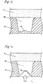
Figure 3 , when theballoon 10 is made to advance towards the implantation site, theholes 16 initially present in the form of blind holes. - The blind hole condition of the
openings 16 is maintained when the inflation liquid that conveyes the active agent is initially made to flow within theballoon 10 and also during the initial step of expansion of theballoon 10, which is obtained at a pressure practically equal to the atmospheric pressure until thewall 14 of theballoon 10 comes into contact with the wall of the vessel V undergoing treatment (see, for example, the condition illustrated inFigure 1 ) . - In the above conditions, the fact that the openings or
passageways 16 are blind holes prevents the active agent from being dispersed in an undesirable way. - After the
wall 14 of theballoon 10 has come into contact with the wall of the vessel V, the vessel V itself starts to offer resistance to the further expansion of theballoon 10, and the pumping action of the syringe S (which may possibly be a motor-driven syringe) induces in the inflation fluid the increase in pressure that underlies the angioplasty treatment, which basically amounts to an action (or more correctly, to a repeated sequence of actions) of forced dilation of the vessel V. - As may be appreciated from an observation of
Figures 4 and5 (where the relative proportions have been deliberately altered for reasons of clarity of illustration) theobturator 18 is intrinsically "thin" with respect to the overall thickness of thewall 14. - Just to clarify the idea -without this implying any limitation of the scope of the invention-, the
wall 14 can have a thickness (measured in a radial direction with respect to the balloon 10) in the region of 10 to 50 µm-i.e., 10 to 50 x 10-6 metres - and theobturator 18 can have (also according to the materials used) a thickness from 10% to 50 % of the thickness of thewall 14. - The increase in pressure of the inflation liquid has the effect of deforming, i.e., bulging, the obturator 18 (in the embodiment illustrated, in which the
obturator 18 is located at the internal end of thehole 16, there is an introflection within the hole itself) until the condition is reached in which, on account of its gradual bulging, the obturator forms a sort of bubble that explodes (Figure 5 ) creating anopening 180. - Just to clarify the idea (once again without this implying any limitation of the scope of the invention) the burst of the
obturators 18 may occur at a pressure from 2 to 10 bar higher than the nominal operating pressure of theballoon 10, hence remaining in safety conditions below the rated burst pressure (RBP) of theballoon 10. - In this way, the
hole 16 is rendered pervious, and the inflation liquid L is able to flow towards the wall of the vessel V so as to produce the desired action of diffusion of the active agent conveyed thereby. - From an observation of
Figure 5 it may be noted that the active agent is practically all conveyed towards the wall of the vessel V. The formation of theopening 180 presupposes in fact that thewall 14 of theballoon 16 is forced in contact against the wall of the vessel V with a pressure equal to the pressure of the inflation liquid L. - This makes it possible to control the release of the active agent, causing delivery of the active agent only after the surface of the dilated balloon, that has come into contact with the vessel wall, starts to perform a real dilation action, for example with certain effect of ablation of the sclerotic plaque.
- As already indicated previously, the angioplasty treatment can envisage an alternating sequence of expansions and contractions of the
balloon 10 obtained by varying correspondingly (i.e., by increasing and decreasing) the pressure of the inflation liquid L. - The decrease in pressure of the inflation liquid leads to detachment of the wall of the
balloon 14 from the wall of the vessel V: the action of deflation is in fact designed to enable flow of the blood within the treated vessel, which would be otherwise occluded by theballoon 10 when theballoon 10 itself is in the dilated condition. - As schematically illustrated in
Figure 6 , the modalities of formation of theopening 180, obtained by bursting a "bubble" created as a result of the deformation of the material forming the obturator 18 (which may be a material such as polyamide, e.g., Nylon 12) means that, when the pressure of the inflation liquid within theballoon 10 drops, theobturator 18 behaves as a whole more or less like the leaflets of a cardiac valve when the direction of the blood through the valve reverses with respect to the direction of free flow. - In other words, when the pressure of the inflation liquid drops, the
obturator 18 tends to return approximately to the original condition so that theopening 180 is in effect choked (see once againFigure 6 ). The deformation of the material such as to lead to the formation of the "bubble", which then bursts giving rise to theopening 180, can in fact bring about a certain stretching of the material constituting the obturator. - Consequently, there is not any undesirable penetration of the blood in the
balloon 10. - In this regard, it is also possible to intervene on the dimensions of the
openings 16, causing them to give rise to phenomena of capillarity in regard to the inflation liquid and the active agent conveyed thereby. These phenomena can be useful to enable diffusion of the inflation liquid L (and of the active agent) towards the wall of the vessel V producing at the same time a trapping effect of possible air bubbles on the body of the balloon 10 - specifically within the openings 16 - preventing any undesirable phenomenon of diffusion of air in the blood flow, this being in any case a phenomenon of altogether minor importance, considering the dimensions of the objects involved. - For example, the
holes 16 may have a diameter of less than 20 µm (20 x 10-6 metres) . - Also the choice of the material constituting the wall 14 (and hence the characteristics of wettability thereof) can come to play a role and be exploited in implementation of the mechanisms outlined above.
- It will moreover be appreciated that when, once the treatment has been completed, the
balloon 10 is finally deflated and then retracted out of the body of the patient, the drop in the pressure of the inflation liquid causes theobturators 18 to return into the original condition, with theopenings 180 choked, thus preventing any undesirable dispersion of residue of active agent in the vascular system of the patient. - With reference to
Figures 3 to 6 in whichinventive obturators 18 are formed as convex frangible septa with the convexity facing the outside of theballoon 10. A septum which is convex towards the outside of theballoon 10 may exert a strong sealing action when the pressure of the inflation liquid within the balloon decreases, because possible flaps of theseptum 18 created following upon burst thereof have a shape slightly arched outwards, which allows to reclose theaperture 180 with an action at least roughly assimilable to the action of the valve leaflets of a valve such as a heart valve. - A
balloon 10 according to the embodiments considered herein can be obtained with various techniques. - For example, considering producing the
balloon 10 with a polyamide-resin-based material, such as the material commercially known asNylon 12, thewall 14 could be produced in the form of a double-layer structure with a thin internal tubular layer designed to constitute theobturators 18 fitted on which is a perforated tubular tunic, whose perforations or pores constitute the open part of theholes 16. The relative arrangement can even be reversed, with the thin layer set on the outside of the perforated tunic, in which case theobturators 18 are located at the outer end of the openings 16 (inFigures 3 to 6 theobturators 18 are instead located at the inner end). Also conceivable is recourse to a sandwich structure, with a thin layer designed to form theobturators 18 set between two perforated tunics, in which case theobturators 18 would be set in an intermediate position with respect to the development of theholes 16. -
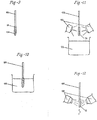
Figures 7 to 11 refer to an example of a method for producing aballoon 10 by resorting to a technique that can be substantially defined as a dipping technique, which can be used, for example, for producingballoons 10 with a base of a silicone material. - In
Figures 7 to 11 , thereference 100 designates a core (in practice a rod) having diametral dimensions that, in one example, substantially correspond to the desired diametral dimensions of theballoon 10 in an expanded condition. - The
core 100 is dipped in asolution 102 of a precursor of the material constituting theballoon 10. When thecore 100 is extracted from thesolution 102, theprecursor 102 forms a thin layer deposited on the wall of thecore 100. In these conditions, thecore 100 is exposed to the action of sources of lighting/heating 104 that bring about consolidation (i.e., curing) of the aforesaid precursor. - The sequence of operations represented in
Figures 7 and 8 can be repeated a number of times according to the thickness desired for the layer of material corresponding to theobturators 18. According to the characteristics of theprecursor 102 the greater the number of times the sequence of operations ofFigures 7 and 8 is repeated, the thicker theobturators 18 will be. It will be appreciated that this procedure enables very precise adjustment of the thickness of theobturators 18 so as to ensure the desired operating modes. -
Figure 9 illustrates the possibility of depositing on the layer of material corresponding to theobturators 18 already formed on the core 100 a granular material 106 (such as, for example, a water-soluble granular material, for instance, granular glucose). Then (Figure 10 ), the operation of dipping of the core 100 in theprecursor 102 is repeated (the precursor is here assumed as being of a nature identical to that of the solution ofFigures 7 and 8 , but it may also be of a different nature, so that at the end theobturators 18 are made of a material different from that of the rest of the wall portion 12). - Also in this case, the operation of extraction and exposure to the sources of lighting/heating 104 (
Figure 11 ) aimed at promoting curing of the precursor can be repeated a number of times until, on thecore 100, of a layer of material corresponding to the full parts of thewall 14 is formed. The areas occupied by the granules of the material 106 correspond, instead, to theopenings 16. - As schematically illustrated in
Figure 12 , once the thickness of thewall 14 has reached the desired value, thecore 100 with the material (cured) 106 deposited thereon is subjected to an operation - such as a washing operation, for example with water jets 108 - aimed at dissolving thematerial 106. In the position occupied by each of said granules, on the structure ofballoon 10 formed on thecore 100, anopening 16 will now be present having the characteristics illustrated inFigures 3 to 6 . - It will be appreciated that the technique represented in
Figures 7 to 12 is substantially equivalent to a technique commonly used for bestowing a granular surface appearance on silicone mammary prostheses. - Of course, without prejudice to the principle of the invention, the details of construction and the embodiments may vary, even significantly, with respect to what has been illustrated herein purely by way of non-limiting example, without thereby departing from the scope of the invention, as defined by the annexed claims.
Claims (6)
- A balloon (10) for an angioplasty catheter expandable by means of a pressurized inflation liquid and including at least one wall portion (12) provided with passageways (16) for diffusing an active agent conveyed by said liquid, wherein the passageways (16) are provided with obturators (18) openable from an original blind hole condition of said passageways (16) under the pressure exerted by said pressurized liquid, wherein the obturators (18) are in the form of septa frangible under the pressure exerted by the pressurized liquid to form openings (180) for the agent conveyed by the pressurized liquid to flow through said passageways (16),
the balloon (10) being characterized in that in said original blind hole condition of said passageways (16) the obturators (18) are in the form of lenticular plano-convex septa with convexity facing outwardly of the balloon (10). - The balloon of claim 1, wherein the obturators (18) are closeable as the pressure of the pressurized liquid diminishes.
- The balloon of any of the previous claims, wherein said wall portion (12) has a radially outer surface and a radially inner surface and wherein the obturators (18) are arranged at the radially inner surface.
- The balloon of any of the previous claims, wherein the obturators (18) comprise portions of reduced thickness of said wall portion (12) of the balloon (10).
- The balloon of any of the previous claims, wherein said wall portion (12) has a layered structure with a layer defining the obturators (18) and at least one perforated layer coupled to the layer defining the obturators (18).
- The balloon of any of the previous claims, wherein:- the obturators (18) are septa having a thickness between 10% and 50% of the thickness of said wall portion (12) of the balloon, and/or- the passageways (16) have a diameter smaller than 20 micron.
Applications Claiming Priority (2)
| Application Number | Priority Date | Filing Date | Title |
|---|---|---|---|
| ITTO2009A000544A IT1399809B1 (en) | 2009-07-20 | 2009-07-20 | BALLOON FOR CATETERS AND ITS PRODUCTION PROCEDURE |
| PCT/IB2010/053275 WO2011010273A2 (en) | 2009-07-20 | 2010-07-19 | A balloon for catheters and related production process |
Publications (2)
| Publication Number | Publication Date |
|---|---|
| EP2456498A2 EP2456498A2 (en) | 2012-05-30 |
| EP2456498B1 true EP2456498B1 (en) | 2019-05-29 |
Family
ID=41662307
Family Applications (1)
| Application Number | Title | Priority Date | Filing Date |
|---|---|---|---|
| EP10752184.1A Active EP2456498B1 (en) | 2009-07-20 | 2010-07-19 | A balloon for catheters |
Country Status (4)
| Country | Link |
|---|---|
| EP (1) | EP2456498B1 (en) |
| ES (1) | ES2743207T3 (en) |
| IT (1) | IT1399809B1 (en) |
| WO (1) | WO2011010273A2 (en) |
Families Citing this family (2)
| Publication number | Priority date | Publication date | Assignee | Title |
|---|---|---|---|---|
| EP2789354A1 (en) * | 2013-04-13 | 2014-10-15 | IPPyramids GmbH | Catheter balloon with micro boreholes and a metal mesh |
| CN115919340B (en) * | 2023-01-05 | 2023-05-23 | 合肥海巍光电科技有限公司 | Portable medical X-ray shooting equipment |
Family Cites Families (17)
| Publication number | Priority date | Publication date | Assignee | Title |
|---|---|---|---|---|
| DE3821544C2 (en) | 1988-06-25 | 1994-04-28 | H Prof Dr Med Just | Dilatation catheter |
| US5100429A (en) | 1989-04-28 | 1992-03-31 | C. R. Bard, Inc. | Endovascular stent and delivery system |
| WO1992011895A1 (en) | 1990-12-28 | 1992-07-23 | Boston Scientific Corporation | Balloon drug delivery system |
| US5213576A (en) | 1991-06-11 | 1993-05-25 | Cordis Corporation | Therapeutic porous balloon catheter |
| US5344402A (en) | 1993-06-30 | 1994-09-06 | Cardiovascular Dynamics, Inc. | Low profile perfusion catheter |
| EP0797463A4 (en) * | 1994-12-14 | 1999-01-27 | Scimed Life Systems Inc | In situ stent forming catheter |
| US5624395A (en) * | 1995-02-23 | 1997-04-29 | Cv Dynamics, Inc. | Urinary catheter having palpitatable valve and balloon and method for making same |
| EP0835673A3 (en) | 1996-10-10 | 1998-09-23 | Schneider (Usa) Inc. | Catheter for tissue dilatation and drug delivery |
| JPH10337328A (en) | 1997-06-09 | 1998-12-22 | Kaneka Medics:Kk | Chemical solution infusion catheter |
| US6048332A (en) * | 1998-10-09 | 2000-04-11 | Ave Connaught | Dimpled porous infusion balloon |
| US6494862B1 (en) | 1999-07-13 | 2002-12-17 | Advanced Cardiovascular Systems, Inc. | Substance delivery apparatus and a method of delivering a therapeutic substance to an anatomical passageway |
| US6585926B1 (en) | 2000-08-31 | 2003-07-01 | Advanced Cardiovascular Systems, Inc. | Method of manufacturing a porous balloon |
| US6544223B1 (en) | 2001-01-05 | 2003-04-08 | Advanced Cardiovascular Systems, Inc. | Balloon catheter for delivering therapeutic agents |
| US8025637B2 (en) * | 2003-07-18 | 2011-09-27 | Boston Scientific Scimed, Inc. | Medical balloons and processes for preparing same |
| US7537580B2 (en) * | 2004-06-23 | 2009-05-26 | Boston Scientific Scimed, Inc. | Intravascular dilatation infusion catheter |
| WO2006114783A2 (en) * | 2005-04-28 | 2006-11-02 | Bypass, Inc. | Material delivery system |
| WO2009036135A1 (en) | 2007-09-12 | 2009-03-19 | Cook Incorporated | Balloon catheter for delivering a therapeutic agent |
-
2009
- 2009-07-20 IT ITTO2009A000544A patent/IT1399809B1/en active
-
2010
- 2010-07-19 WO PCT/IB2010/053275 patent/WO2011010273A2/en not_active Ceased
- 2010-07-19 ES ES10752184T patent/ES2743207T3/en active Active
- 2010-07-19 EP EP10752184.1A patent/EP2456498B1/en active Active
Non-Patent Citations (1)
| Title |
|---|
| None * |
Also Published As
| Publication number | Publication date |
|---|---|
| EP2456498A2 (en) | 2012-05-30 |
| WO2011010273A2 (en) | 2011-01-27 |
| IT1399809B1 (en) | 2013-05-03 |
| ITTO20090544A1 (en) | 2011-01-21 |
| ES2743207T3 (en) | 2020-02-18 |
| WO2011010273A3 (en) | 2011-04-07 |
Similar Documents
| Publication | Publication Date | Title |
|---|---|---|
| CA2162970C (en) | Shape memory locking mechanism for intravascular stent | |
| US4776337A (en) | Expandable intraluminal graft, and method and apparatus for implanting an expandable intraluminal graft | |
| US6620192B1 (en) | Multilayer stent | |
| EP2833844B1 (en) | Control of balloon inflation rate during deployment of scaffold | |
| US8882822B2 (en) | Non-thrombogenic stent jacket | |
| US6419657B1 (en) | Flow regulator valve to optimize stent deployment and method of using the same | |
| EP1871439B1 (en) | Hybrid biodegradable/non-biodegradable stent, delivery system and method of treating a vascular condition | |
| KR20180067537A (en) | Implantable Valves and Methods | |
| EP0712615A1 (en) | Drug-loaded elastic membrane and method for delivery | |
| US20160361186A1 (en) | Stents and catheters having improved stent deployment | |
| CN107334562A (en) | Implantable medical device delivery system | |
| US20050278011A1 (en) | Stent delivery system | |
| EP2789312A1 (en) | Expandable stent-valve and method for manufacturing a stent | |
| CA2111455A1 (en) | Multilayered biodegradable stent and method for its manufacture | |
| EP1517653A1 (en) | Methods and devices for treating aneurysms | |
| EP3322387B1 (en) | Balloon catheter | |
| EP3038694B1 (en) | Integrated balloon catheter inflation system | |
| WO2011010273A2 (en) | A balloon for catheters and related production process | |
| WO2001017459A1 (en) | System for removably securing a stent on a catheter assembly and method of use | |
| US10751204B2 (en) | Drug-eluting stent formed from a deformable hollow strut for a customizable elution rate | |
| CN114569292A (en) | Non-choking balloon | |
| CN117942206B (en) | A recyclable drug delivery system and its application | |
| WO2026010611A1 (en) | Balloon catheter system for delivery of therapeutic agent | |
| AU722466B2 (en) | Shape memory locking mechanism for intravascular stent | |
| HK1206584B (en) | Control of balloon inflation rate during deployment of scaffold |
Legal Events
| Date | Code | Title | Description |
|---|---|---|---|
| PUAI | Public reference made under article 153(3) epc to a published international application that has entered the european phase |
Free format text: ORIGINAL CODE: 0009012 |
|
| 17P | Request for examination filed |
Effective date: 20120117 |
|
| AK | Designated contracting states |
Kind code of ref document: A2 Designated state(s): AL AT BE BG CH CY CZ DE DK EE ES FI FR GB GR HR HU IE IS IT LI LT LU LV MC MK MT NL NO PL PT RO SE SI SK SM TR |
|
| DAX | Request for extension of the european patent (deleted) | ||
| 17Q | First examination report despatched |
Effective date: 20130514 |
|
| GRAP | Despatch of communication of intention to grant a patent |
Free format text: ORIGINAL CODE: EPIDOSNIGR1 |
|
| STAA | Information on the status of an ep patent application or granted ep patent |
Free format text: STATUS: GRANT OF PATENT IS INTENDED |
|
| INTG | Intention to grant announced |
Effective date: 20181219 |
|
| GRAS | Grant fee paid |
Free format text: ORIGINAL CODE: EPIDOSNIGR3 |
|
| GRAA | (expected) grant |
Free format text: ORIGINAL CODE: 0009210 |
|
| STAA | Information on the status of an ep patent application or granted ep patent |
Free format text: STATUS: THE PATENT HAS BEEN GRANTED |
|
| AK | Designated contracting states |
Kind code of ref document: B1 Designated state(s): AL AT BE BG CH CY CZ DE DK EE ES FI FR GB GR HR HU IE IS IT LI LT LU LV MC MK MT NL NO PL PT RO SE SI SK SM TR |
|
| REG | Reference to a national code |
Ref country code: GB Ref legal event code: FG4D |
|
| REG | Reference to a national code |
Ref country code: CH Ref legal event code: EP |
|
| REG | Reference to a national code |
Ref country code: AT Ref legal event code: REF Ref document number: 1137914 Country of ref document: AT Kind code of ref document: T Effective date: 20190615 |
|
| REG | Reference to a national code |
Ref country code: DE Ref legal event code: R096 Ref document number: 602010059170 Country of ref document: DE |
|
| REG | Reference to a national code |
Ref country code: IE Ref legal event code: FG4D |
|
| RAP2 | Party data changed (patent owner data changed or rights of a patent transferred) |
Owner name: CID S.P.A. |
|
| REG | Reference to a national code |
Ref country code: DE Ref legal event code: R081 Ref document number: 602010059170 Country of ref document: DE Owner name: CID S.P.A., SALUGGIA, IT Free format text: FORMER OWNER: CID S.R.L., SALUGGIA, VC, IT |
|
| REG | Reference to a national code |
Ref country code: NL Ref legal event code: MP Effective date: 20190529 |
|
| REG | Reference to a national code |
Ref country code: LT Ref legal event code: MG4D |
|
| PG25 | Lapsed in a contracting state [announced via postgrant information from national office to epo] |
Ref country code: FI Free format text: LAPSE BECAUSE OF FAILURE TO SUBMIT A TRANSLATION OF THE DESCRIPTION OR TO PAY THE FEE WITHIN THE PRESCRIBED TIME-LIMIT Effective date: 20190529 Ref country code: AL Free format text: LAPSE BECAUSE OF FAILURE TO SUBMIT A TRANSLATION OF THE DESCRIPTION OR TO PAY THE FEE WITHIN THE PRESCRIBED TIME-LIMIT Effective date: 20190529 Ref country code: NO Free format text: LAPSE BECAUSE OF FAILURE TO SUBMIT A TRANSLATION OF THE DESCRIPTION OR TO PAY THE FEE WITHIN THE PRESCRIBED TIME-LIMIT Effective date: 20190829 Ref country code: SE Free format text: LAPSE BECAUSE OF FAILURE TO SUBMIT A TRANSLATION OF THE DESCRIPTION OR TO PAY THE FEE WITHIN THE PRESCRIBED TIME-LIMIT Effective date: 20190529 Ref country code: LT Free format text: LAPSE BECAUSE OF FAILURE TO SUBMIT A TRANSLATION OF THE DESCRIPTION OR TO PAY THE FEE WITHIN THE PRESCRIBED TIME-LIMIT Effective date: 20190529 Ref country code: HR Free format text: LAPSE BECAUSE OF FAILURE TO SUBMIT A TRANSLATION OF THE DESCRIPTION OR TO PAY THE FEE WITHIN THE PRESCRIBED TIME-LIMIT Effective date: 20190529 Ref country code: PT Free format text: LAPSE BECAUSE OF FAILURE TO SUBMIT A TRANSLATION OF THE DESCRIPTION OR TO PAY THE FEE WITHIN THE PRESCRIBED TIME-LIMIT Effective date: 20190930 |
|
| PG25 | Lapsed in a contracting state [announced via postgrant information from national office to epo] |
Ref country code: LV Free format text: LAPSE BECAUSE OF FAILURE TO SUBMIT A TRANSLATION OF THE DESCRIPTION OR TO PAY THE FEE WITHIN THE PRESCRIBED TIME-LIMIT Effective date: 20190529 Ref country code: GR Free format text: LAPSE BECAUSE OF FAILURE TO SUBMIT A TRANSLATION OF THE DESCRIPTION OR TO PAY THE FEE WITHIN THE PRESCRIBED TIME-LIMIT Effective date: 20190830 Ref country code: BG Free format text: LAPSE BECAUSE OF FAILURE TO SUBMIT A TRANSLATION OF THE DESCRIPTION OR TO PAY THE FEE WITHIN THE PRESCRIBED TIME-LIMIT Effective date: 20190829 |
|
| REG | Reference to a national code |
Ref country code: AT Ref legal event code: MK05 Ref document number: 1137914 Country of ref document: AT Kind code of ref document: T Effective date: 20190529 |
|
| PG25 | Lapsed in a contracting state [announced via postgrant information from national office to epo] |
Ref country code: AT Free format text: LAPSE BECAUSE OF FAILURE TO SUBMIT A TRANSLATION OF THE DESCRIPTION OR TO PAY THE FEE WITHIN THE PRESCRIBED TIME-LIMIT Effective date: 20190529 Ref country code: DK Free format text: LAPSE BECAUSE OF FAILURE TO SUBMIT A TRANSLATION OF THE DESCRIPTION OR TO PAY THE FEE WITHIN THE PRESCRIBED TIME-LIMIT Effective date: 20190529 Ref country code: EE Free format text: LAPSE BECAUSE OF FAILURE TO SUBMIT A TRANSLATION OF THE DESCRIPTION OR TO PAY THE FEE WITHIN THE PRESCRIBED TIME-LIMIT Effective date: 20190529 Ref country code: SK Free format text: LAPSE BECAUSE OF FAILURE TO SUBMIT A TRANSLATION OF THE DESCRIPTION OR TO PAY THE FEE WITHIN THE PRESCRIBED TIME-LIMIT Effective date: 20190529 Ref country code: RO Free format text: LAPSE BECAUSE OF FAILURE TO SUBMIT A TRANSLATION OF THE DESCRIPTION OR TO PAY THE FEE WITHIN THE PRESCRIBED TIME-LIMIT Effective date: 20190529 Ref country code: NL Free format text: LAPSE BECAUSE OF FAILURE TO SUBMIT A TRANSLATION OF THE DESCRIPTION OR TO PAY THE FEE WITHIN THE PRESCRIBED TIME-LIMIT Effective date: 20190529 Ref country code: CZ Free format text: LAPSE BECAUSE OF FAILURE TO SUBMIT A TRANSLATION OF THE DESCRIPTION OR TO PAY THE FEE WITHIN THE PRESCRIBED TIME-LIMIT Effective date: 20190529 |
|
| REG | Reference to a national code |
Ref country code: ES Ref legal event code: FG2A Ref document number: 2743207 Country of ref document: ES Kind code of ref document: T3 Effective date: 20200218 |
|
| PG25 | Lapsed in a contracting state [announced via postgrant information from national office to epo] |
Ref country code: MC Free format text: LAPSE BECAUSE OF FAILURE TO SUBMIT A TRANSLATION OF THE DESCRIPTION OR TO PAY THE FEE WITHIN THE PRESCRIBED TIME-LIMIT Effective date: 20190529 Ref country code: SM Free format text: LAPSE BECAUSE OF FAILURE TO SUBMIT A TRANSLATION OF THE DESCRIPTION OR TO PAY THE FEE WITHIN THE PRESCRIBED TIME-LIMIT Effective date: 20190529 |
|
| REG | Reference to a national code |
Ref country code: CH Ref legal event code: PL |
|
| REG | Reference to a national code |
Ref country code: DE Ref legal event code: R097 Ref document number: 602010059170 Country of ref document: DE |
|
| PLBE | No opposition filed within time limit |
Free format text: ORIGINAL CODE: 0009261 |
|
| STAA | Information on the status of an ep patent application or granted ep patent |
Free format text: STATUS: NO OPPOSITION FILED WITHIN TIME LIMIT |
|
| REG | Reference to a national code |
Ref country code: BE Ref legal event code: MM Effective date: 20190731 |
|
| PG25 | Lapsed in a contracting state [announced via postgrant information from national office to epo] |
Ref country code: PL Free format text: LAPSE BECAUSE OF FAILURE TO SUBMIT A TRANSLATION OF THE DESCRIPTION OR TO PAY THE FEE WITHIN THE PRESCRIBED TIME-LIMIT Effective date: 20190529 |
|
| 26N | No opposition filed |
Effective date: 20200303 |
|
| PG25 | Lapsed in a contracting state [announced via postgrant information from national office to epo] |
Ref country code: SI Free format text: LAPSE BECAUSE OF FAILURE TO SUBMIT A TRANSLATION OF THE DESCRIPTION OR TO PAY THE FEE WITHIN THE PRESCRIBED TIME-LIMIT Effective date: 20190529 Ref country code: CH Free format text: LAPSE BECAUSE OF NON-PAYMENT OF DUE FEES Effective date: 20190731 Ref country code: LI Free format text: LAPSE BECAUSE OF NON-PAYMENT OF DUE FEES Effective date: 20190731 Ref country code: LU Free format text: LAPSE BECAUSE OF NON-PAYMENT OF DUE FEES Effective date: 20190719 Ref country code: BE Free format text: LAPSE BECAUSE OF NON-PAYMENT OF DUE FEES Effective date: 20190731 |
|
| PG25 | Lapsed in a contracting state [announced via postgrant information from national office to epo] |
Ref country code: IE Free format text: LAPSE BECAUSE OF NON-PAYMENT OF DUE FEES Effective date: 20190719 |
|
| PG25 | Lapsed in a contracting state [announced via postgrant information from national office to epo] |
Ref country code: CY Free format text: LAPSE BECAUSE OF FAILURE TO SUBMIT A TRANSLATION OF THE DESCRIPTION OR TO PAY THE FEE WITHIN THE PRESCRIBED TIME-LIMIT Effective date: 20190529 |
|
| PG25 | Lapsed in a contracting state [announced via postgrant information from national office to epo] |
Ref country code: IS Free format text: LAPSE BECAUSE OF FAILURE TO SUBMIT A TRANSLATION OF THE DESCRIPTION OR TO PAY THE FEE WITHIN THE PRESCRIBED TIME-LIMIT Effective date: 20190929 |
|
| PG25 | Lapsed in a contracting state [announced via postgrant information from national office to epo] |
Ref country code: HU Free format text: LAPSE BECAUSE OF FAILURE TO SUBMIT A TRANSLATION OF THE DESCRIPTION OR TO PAY THE FEE WITHIN THE PRESCRIBED TIME-LIMIT; INVALID AB INITIO Effective date: 20100719 Ref country code: MT Free format text: LAPSE BECAUSE OF FAILURE TO SUBMIT A TRANSLATION OF THE DESCRIPTION OR TO PAY THE FEE WITHIN THE PRESCRIBED TIME-LIMIT Effective date: 20190529 |
|
| PG25 | Lapsed in a contracting state [announced via postgrant information from national office to epo] |
Ref country code: MK Free format text: LAPSE BECAUSE OF FAILURE TO SUBMIT A TRANSLATION OF THE DESCRIPTION OR TO PAY THE FEE WITHIN THE PRESCRIBED TIME-LIMIT Effective date: 20190529 |
|
| P01 | Opt-out of the competence of the unified patent court (upc) registered |
Effective date: 20230531 |
|
| PGFP | Annual fee paid to national office [announced via postgrant information from national office to epo] |
Ref country code: ES Payment date: 20250806 Year of fee payment: 16 |
|
| PGFP | Annual fee paid to national office [announced via postgrant information from national office to epo] |
Ref country code: DE Payment date: 20250708 Year of fee payment: 16 |
|
| PGFP | Annual fee paid to national office [announced via postgrant information from national office to epo] |
Ref country code: TR Payment date: 20250716 Year of fee payment: 16 Ref country code: IT Payment date: 20250722 Year of fee payment: 16 |
|
| PGFP | Annual fee paid to national office [announced via postgrant information from national office to epo] |
Ref country code: GB Payment date: 20250710 Year of fee payment: 16 |
|
| PGFP | Annual fee paid to national office [announced via postgrant information from national office to epo] |
Ref country code: FR Payment date: 20250708 Year of fee payment: 16 |