EP2456078A1 - Method and device for frequency deviation pre-correction - Google Patents
Method and device for frequency deviation pre-correction Download PDFInfo
- Publication number
- EP2456078A1 EP2456078A1 EP10799350A EP10799350A EP2456078A1 EP 2456078 A1 EP2456078 A1 EP 2456078A1 EP 10799350 A EP10799350 A EP 10799350A EP 10799350 A EP10799350 A EP 10799350A EP 2456078 A1 EP2456078 A1 EP 2456078A1
- Authority
- EP
- European Patent Office
- Prior art keywords
- frequency deviation
- value
- user equipment
- uplink frequency
- calibration
- Prior art date
- Legal status (The legal status is an assumption and is not a legal conclusion. Google has not performed a legal analysis and makes no representation as to the accuracy of the status listed.)
- Granted
Links
Images
Classifications
-
- H—ELECTRICITY
- H04—ELECTRIC COMMUNICATION TECHNIQUE
- H04L—TRANSMISSION OF DIGITAL INFORMATION, e.g. TELEGRAPHIC COMMUNICATION
- H04L27/00—Modulated-carrier systems
- H04L27/26—Systems using multi-frequency codes
- H04L27/2601—Multicarrier modulation systems
- H04L27/2647—Arrangements specific to the receiver only
- H04L27/2655—Synchronisation arrangements
- H04L27/2657—Carrier synchronisation
Definitions
- Fig. 4 illustrates a schematic diagram of frequency deviations of transmitted and received signals of the base station and the user equipment after and before the handover, where bracketed values represent the transmission and reception frequencies of the base station or the user equipment.
- the user equipment transmits a signal at the frequency fc, and the base station receives at the frequency fc the signal with the frequency of fc+fd over an uplink channel and can estimate a frequency deviation of fd.
- a frequency deviation determination unit configured to acquire a historical uplink frequency deviation pre-calibration value for frequency deviation pre-calibration on the user equipment and to determine from the historical uplink frequency deviation pre-calibration value a current uplink frequency deviation pre-calibration value of the user equipment which is closer to the estimated uplink frequency deviation value than the historical uplink frequency deviation pre-calibration value;
- a frequency deviation pre-calibration unit configured to perform frequency deviation pre-calibration on the user equipment with the current uplink frequency deviation pre-calibration value.
- the value of the iteratively smoothing factor b shall be determined in combination with a solution of adjusting the local oscillator of the user equipment and therefore can be determined in the following formula:
- the base station can determine the current uplink frequency deviation pre-calibration value of the user equipment so that the uplink frequency deviation pre-calibration value is closer to the estimated uplink frequency deviation value than the historical uplink frequency deviation pre-calibration value in the operation 61 alternatively in numerous other implementation methods than the foregoing two formulas. For example, firstly the difference between the uplink frequency deviation value and the historical uplink frequency deviation pre-calibration value is determined, and a convergent step factor is set according to the difference so that the absolute value of the convergent step factor is below twice the difference, and then the convergent step factor is added to the historical uplink frequency deviation pre-calibration value, and the sum thereof is taken as the current uplink frequency deviation pre-calibration value.
- f u,c (n-1) and f u,c (n-2), f u,c (n-2) and f u,c (n-3), etc. can alternatively be used as the two uplink frequency deviation values of the user equipment estimated by the base station.
- the base station further includes:
- the base station transmits a signal to the user equipment at a frequency closer to f c -f d after frequency deviation pre-calibration is performed with the current uplink frequency deviation pre-calibration value, and then the user equipment receives the signal at a frequency closer to f c over a channel with the Doppler frequency shift, where f c is the operating frequency of the base station, so that there is no significant frequency deviation in the demodulated signal of the user equipment to thereby improve effectively the performance of detecting the signal at the user equipment.
Landscapes
- Engineering & Computer Science (AREA)
- Computer Networks & Wireless Communication (AREA)
- Signal Processing (AREA)
- Mobile Radio Communication Systems (AREA)
- Circuits Of Receivers In General (AREA)
Abstract
Description
- This application claims the benefit of Chinese Patent Application No.
200910088287.7 - The present invention relates to the field of radio communications and particularly to a frequency deviation pre-calibration method and device.
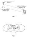
- In a mobile communication system, a base station transmits and receives signals of multiple users at a fixed frequency fc, and a user equipment tracks the frequency of a received signal through Automatic Frequency Control (AFC). In a high-speed movement context, the base station transmits a signal at the frequency fc, and the user equipment receives the signal at a frequency of fc+Δf over a channel, where Δf is a Doppler frequency shift, and both the transmission and reception frequencies of the user equipment settle down around the frequency fc+Δf of the received signal after a period of time elapses. Thus the user equipment transmits a signal at the frequency of fc+Δf, and the base station receives the signal at a frequency of fc+2Δf over an uplink channel, but the reception frequency of the base station is fc, that is, the base station receives the signal with the maximum frequency deviation of 2Δf, as illustrated in
Fig. 1 . - A user equipment moves away from a base station prior to a cell handover, and the reception frequency of the user equipment settles down around fc-fd as calculated from a Doppler frequency shift. The user equipment moves to a new base station after the handover and receives a signal with a frequency of fc+fd, but the user equipment receives the signal still at the frequency of fc-fd due to the delay of the AFC, thus the user equipment detects the signal with a frequency deviation instantly increased to the maximum value of 2fd, as illustrated in
Fig. 2 , where bracketed values represent the transmission and reception frequencies of the base station or the user equipment. - The jump of the frequency deviation influences the user equipment due to the sudden increase of the frequency deviation, which causes the performance of the user equipment to deteriorate sharply in a period of time after the handover so that a user may suffer from a degraded experience and even a dropout. Taking a Time Division-Synchronization Code Division Multiple Access (TD-SCDMA) system as an example, the frequency deviation may be up to 1500 Hz in high-speed movement context of 400 Km/h, and the demodulation performance of the user equipment may deteriorate seriously, therefore a solution of frequency deviation pre-calibration at the base station has to be introduced to improve the demodulation performance of the user equipment.
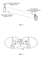
- As illustrated in
Fig. 3 , a fundamental idea of frequency deviation pre-calibration lies in that the base station estimates the Doppler frequency deviation of fd over an uplink channel of a target user and pre-calibrates the frequency of a signal for downlink transmission to the user by the estimated frequency deviation, that is, the downlink transmission frequency is adjusted to fc-fd to pre-compensate for the influence of the downlink frequency deviation so that the user equipment receives the signal with a frequency around the frequency fc and there is no significant influence of the Doppler frequency deviation upon the signal detected by the user equipment to thereby improve the detection performance of the user equipment. - With frequency deviation pre-calibration at the base station, the user equipment hardly experiences an obvious change in the frequency deviation during the cell handover, and here
Fig. 4 illustrates a schematic diagram of frequency deviations of transmitted and received signals of the base station and the user equipment after and before the handover, where bracketed values represent the transmission and reception frequencies of the base station or the user equipment. The user equipment transmits a signal at the frequency fc, and the base station receives at the frequency fc the signal with the frequency of fc+fd over an uplink channel and can estimate a frequency deviation of fd. The base station transmitting data to be transmitted to the user in the downlink adjusts the transmission frequency to fc-fd so that the user equipment receives the transmitted signal still at the frequency fc over a downlink channel. The user equipment operates at a frequency stabilized around the cell frequency fc prior to the handover and at a new cell frequency after the handover to thereby alleviate the change in the frequency deviation of the user equipment and to improve the demodulation performance of the user equipment. This solution improves the performance of a network at the cost of increased complexity of the base station. -
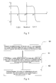
Fig. 5 illustrates a schematic diagram of a change in a Doppler frequency shift over a high-speed movement channel, and taking a TD-SCDMA system as an example, a frequency locking process is performed for a powered-on user equipment over a broadcast channel, e.g., a Downlink Pilot Time Slot (DwPTS), a Primary Common Control Physical Channel (PCCPCH), etc., and a local oscillator of the frequency locked user equipment operates at the frequency of a received signal. As can be apparent from the relationship of the change in a Doppler frequency shift inFig. 5 , the user equipment is locked at a frequency changing with the location where it is powered on, and the frequency ranges from fc-fd to fc+fd in Hz, where fc represents the frequency of a signal transmitted from the base station and fd represents the maximum Doppler frequency shift. - The existing solution of frequency deviation pre-calibration can not be applied to the broadcast channel, and therefore with the Doppler frequency shift fd of the channel, the user equipment is locked at the frequency of fc+fd, and here a frequency deviation of 2fd is estimated at the side of the base station. If a service is being set up while performing a frequency deviation pre-calibration process over a service channel, then transmission over the service channel is at a frequency of fc-2fd, and the user equipment receives a signal at the frequency of fc-fd over the channel, but the local oscillator of the user equipment operates at the frequency of fc+fd. Here the demodulated signal of the user equipment may be subject to a frequency deviation of 2fd, which is approximately 1500 Hz at a vehicle speed of 400 Km/h in the TD-SCDMA system, thus the performance of detecting the signal at the user equipment may deteriorate seriously.
- Embodiments of the invention provide a frequency deviation pre-calibration method and device to improve the performance of detecting a signal at a user equipment.
- An embodiment of the invention provides a frequency deviation pre-calibration method including:
- estimating an uplink frequency deviation value of a user equipment and acquiring a historical uplink frequency deviation pre-calibration value for frequency deviation pre-calibration on the user equipment;
- determining from the historical uplink frequency deviation pre-calibration value a current uplink frequency deviation pre-calibration value of the user equipment which is closer to the estimated uplink frequency deviation value than the historical uplink frequency deviation pre-calibration value; and
- performing frequency deviation pre-calibration on the user equipment with the current uplink frequency deviation pre-calibration value.
- An embodiment of the invention provides a base station including:
- a frequency deviation estimation unit configured to estimate an uplink frequency deviation value of a user equipment;
- a frequency deviation determination unit configured to acquire a historical uplink frequency deviation pre-calibration value for frequency deviation pre-calibration on the user equipment and to determine from the historical uplink frequency deviation pre-calibration value a current uplink frequency deviation pre-calibration value of the user equipment which is closer to the estimated uplink frequency deviation value than the historical uplink frequency deviation pre-calibration value; and
- a frequency deviation pre-calibration unit configured to perform frequency deviation pre-calibration on the user equipment with the current uplink frequency deviation pre-calibration value.
- In the invention, a base station estimates an uplink frequency deviation value of a user equipment, acquires a historical uplink frequency deviation pre-calibration value for frequency deviation pre-calibration on the user equipment, determines a current uplink frequency deviation pre-calibration value of the user equipment which is closer to the estimated uplink frequency deviation value than the historical uplink frequency deviation pre-calibration value, and then performs frequency deviation pre-calibration on the user equipment with the determined current uplink frequency deviation pre-calibration value. Since the current uplink frequency deviation pre-calibration value currently used for frequency deviation pre-calibration on the user equipment is generally closer to the uplink frequency deviation value fd than the lastly used historical uplink frequency deviation pre-calibration value, the base station transmits a signal to the user equipment at a frequency closer to fc-fd after frequency deviation pre-calibration is performed with the current uplink frequency deviation pre-calibration value, and then the user equipment receives the signal at a frequency closer to fc over a channel with the Doppler frequency shift, where fc is the operating frequency of the base station, so that there is no significant frequency deviation in the demodulated signal of the user equipment to thereby improve effectively the performance of detecting the signal at the user equipment.
-
Fig. 1 is a schematic diagram of signal transmission and reception frequencies without a solution of frequency deviation pre-calibration in the prior art; -
Fig. 2 is a schematic diagram of the signal transmission and reception frequencies for a cell handover of a user equipment without the solution of frequency deviation pre-calibration in the prior art; -
Fig. 3 is a schematic diagram of the signal transmission and reception frequencies with the solution of frequency deviation pre-calibration in the prior art; -
Fig. 4 is a schematic diagram of the signal transmission and reception frequencies for the cell handover of the user equipment with the solution of frequency deviation pre-calibration in the prior art; -
Fig. 5 is a schematic diagram of a change in a Doppler frequency shift over a high-speed movement channel in the prior art; -
Fig. 6 is a schematic flow chart of a method according to an embodiment of the invention; and -
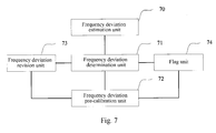
Fig. 7 is a schematic diagram of the structure of a base station according to an embodiment of the invention. - In order to improve the performance of detecting a signal at a user equipment, an embodiment of the invention provides a frequency deviation pre-calibration method in which an uplink frequency deviation pre-calibration value to be used for current frequency deviation pre-calibration on a user equipment is determined according to an estimated uplink frequency deviation value of the user equipment and a historical uplink frequency deviation pre-calibration value for frequency deviation pre-calibration on the user equipment.
- Referring to
Fig. 6 , a frequency deviation pre-calibration method according to an embodiment of the invention particularly includes the followingoperations 60 to 62. - The
operation 60 is to estimate an uplink frequency deviation value of a user equipment and to acquire a historical uplink frequency deviation pre-calibration value for frequency deviation pre-calibration on the user equipment; - The
operation 61 is to determine a current uplink frequency deviation pre-calibration value of the user equipment which is closer to the estimated uplink frequency deviation value than the historical uplink frequency deviation pre-calibration value; and - The
operation 62 is to perform frequency deviation pre-calibration on the user equipment with the determined current uplink frequency deviation pre-calibration value. - In the
operation 61, the current uplink frequency deviation pre-calibration value of the user equipment can be determined in the following formula:
- Where fu,p(n) is an uplink frequency deviation pre-calibration value of the nth sub-frame of the uth user equipment, i.e., the current uplink frequency deviation pre-calibration value; fu,c(n) is an estimated uplink frequency deviation value of the nth sub-frame of the uth user equipment; fu,p(n-m) is an uplink frequency deviation pre-calibration value of the (n-m)th sub-frame of the uth user equipment, i.e., the historical uplink frequency deviation pre-calibration value; and am and b are iteratively smoothing factors above 0 and below 1 and the sum of the iteratively smoothing factors is equal to 1, and M is an integer which is not less than 1.
- With the value of m being only 1, the foregoing formula is rewritten as:

- An execution body of the
operations 60 to 62 may be a base station or any other network entity capable of estimating an uplink frequency deviation value of the user equipment and performing frequency deviation pre-calibration on the user equipment. When the execution body is a base station, if the user equipment establishes a service connection with the base station while a service is being set up for the user equipment, an initial value of fu,p(n) may be 0 or a preset first frequency deviation value which is a frequency deviation value determined from simulation in an estimated frequency deviation range of a system without significantly deteriorating the performance of the system. For example, the first frequency deviation value may range from 0 to 200 Hz in a TD system. - If a service set up at a source base station has to be continued after the user equipment is handed over to a base station, that is, when the user equipment is handed over to the base station after establishing a service connection with another base station than the base station, then the initial value of fu,p(n) may be a preset second frequency deviation value or an uplink frequency deviation pre-calibration value for frequency deviation pre-calibration of the another base station on the user equipment.
- The second frequency deviation value takes a value around the value of the maximum Doppler frequency shift of the user equipment. For example, the second frequency deviation value may range from 500 to 1500 Hz in a TD system. For example, the second frequency deviation value may take the value of 600 Hz in the Doppler frequency shift formula when the user equipment moves at a speed of 200 km/h, the second frequency deviation value may take the value of 1000 Hz in the Doppler frequency shift formula when the user equipment moves at a speed of 300 km/h, and the second frequency deviation value may take the value of 1300 Hz in the Doppler frequency shift formula when the user equipment moves at a speed of 400 km/h.
- When the initial value of fu,p(n) takes an uplink frequency deviation pre-calibration value for frequency deviation pre-calibration of the another base station on the user equipment, the another base station prior to the handover shall transmit the uplink frequency deviation pre-calibration value for frequency deviation pre-calibration on the user equipment to the base station after the handover. Specifically in a 2nd Generation (2G) communication system, the another base station prior to the handover shall transmit the uplink frequency deviation pre-calibration value to the base station after the handover through a Base Station Controller (BSC); in a 3rd Generation (3G) communication system, the another base station prior to the handover shall transmit the uplink frequency deviation pre-calibration value to the base station after the handover through a Radio Network Controller (RNC); and in a long Term Evolution (LTE) communication system, the another base station prior to the handover shall transmit the uplink frequency deviation pre-calibration value to the base station after the handover directly through an interface with the base station after the handover. The uplink frequency deviation pre-calibration value for the another base station prior to the handover to perform frequency deviation pre-calibration on the user equipment can be an estimated uplink frequency deviation value or an uplink frequency deviation pre-calibration value determined as in the
operation 61. - In order to ensure that a local oscillator of the user equipment moving at a high speed be adjusted at a speed approximate to a speed at which the uplink frequency deviation pre-calibration value fu,p(n) in the formula varies, the value of the iteratively smoothing factor b shall be determined in combination with a solution of adjusting the local oscillator of the user equipment and therefore can be determined in the following formula:
- b = the adjustment amount of the local oscillator of the user equipment / (the adjustment period of the local oscillator of the user equipment * a third frequency deviation value), where the third frequency deviation value ranges from the Doppler frequency deviation fd of the user equipment and twice the Doppler frequency deviation, i.e., 2fd. For example, the third frequency deviation value may take the value of fd when the user equipment moves at a speed of 200 km/h, and the third frequency deviation value may take the value of 2fd when the user equipment moves at a speed of 400 km/h.
- Of course the base station can determine the current uplink frequency deviation pre-calibration value of the user equipment so that the uplink frequency deviation pre-calibration value is closer to the estimated uplink frequency deviation value than the historical uplink frequency deviation pre-calibration value in the
operation 61 alternatively in numerous other implementation methods than the foregoing two formulas. For example, firstly the difference between the uplink frequency deviation value and the historical uplink frequency deviation pre-calibration value is determined, and a convergent step factor is set according to the difference so that the absolute value of the convergent step factor is below twice the difference, and then the convergent step factor is added to the historical uplink frequency deviation pre-calibration value, and the sum thereof is taken as the current uplink frequency deviation pre-calibration value. For example, if the historical uplink frequency deviation pre-calibration value is 2, the estimated uplink frequency deviation value is 5, and the convergent step factor is set to 1, then the current uplink frequency deviation pre-calibration value is 2plus 1, i.e., 3, and hence closer to the uplink frequency deviation value than the historical uplink frequency deviation pre-calibration value. In another example, if the historical uplink frequency deviation pre-calibration value is 8, the estimated uplink frequency deviation value is 5, and the convergent step factor is set to -1, then the current uplink frequency deviation pre-calibration value is 8minus 1, i.e., 7, and hence closer to the uplink frequency deviation value than the historical uplink frequency deviation pre-calibration value. Therefore any implementation method in which the current uplink frequency deviation pre-calibration value closer to the uplink frequency deviation value than the historical uplink frequency deviation pre-calibration value can be determined will come into the claimed scope of the invention. - The base station performs frequency deviation pre-calibration on the user equipment with the current uplink frequency deviation pre-calibration value in the
operation 62 particularly by performing frequency deviation pre-calibration on data to be transmitted to the user equipment and then transmitting the data at a rated carrier frequency of fc - f u,p, where fc is the operating frequency of the base station, and fu,p is the determined current uplink frequency deviation pre-calibration value. - Preferably after the base station determines the current uplink frequency deviation pre-calibration value of the user equipment and before it performs frequency deviation pre-calibration on the user equipment with the current uplink frequency deviation pre-calibration value, the base station determines the difference between the estimated uplink frequency deviation value and a historical uplink frequency deviation value estimated before the uplink frequency deviation value is estimated, for example, the difference between fu,c(n) and fu,c(n -1) is determined; and determines whether the difference is above a preset first frequency deviation threshold, and if so, then the base station sums up the current uplink frequency deviation pre-calibration value determined in the
operation 61 and the difference and takes the sum as the frequency deviation value for frequency deviation pre-calibration. Of course another historical frequency deviation value, e.g., fu,c(n - 2), fu,c(n - 3), etc., may alternatively be used to take the difference between the uplink frequency deviation values here. - As can be apparent from the relationship curve of the change in a Doppler frequency shift with traversal of the user equipment across cells illustrated in
Fig. 5 , the Doppler frequency shift will change rapidly while the user equipment is traversing a coverage area of the base station. Here the variation amount of an estimation result of the frequency deviation can be tracked, and when this variation amount exceeds the set first frequency deviation threshold, it is determined that the Doppler frequency shift over a channel here is changing rapidly, and the variation amount can be added to the frequency deviation pre-calibration value fu,p(n) to ensure the ability of the frequency deviation pre-calibration value to catch up with the changing Doppler frequency shift. - The first frequency deviation threshold can be set with reference to the variation amount in a unit of time of the rapidly changing channel. Specifically two uplink frequency deviation values of the user equipment estimated by the base station are acquired, and the first difference between the two uplink frequency deviation values is determined, then the second difference between the times that the two uplink frequency deviation values are estimated is determined, next the ratio of the first difference to the second difference is determined, and the value of the first frequency deviation threshold is set to the ratio. For example, the value of the first frequency deviation threshold can be determined in the following formula:

- Where fu,c(n) is an estimated uplink frequency deviation value of the nth sub-frame of the uth user equipment, fu,c(n -1) is an estimated uplink frequency deviation value of the (n-1)th sub-frame of the uth user equipment, t1 is the time that fu,c(n) is estimated, and t2 is the time that fu,c(n -1) is estimated.
- Of course other values, e.g., fu,c(n-1) and fu,c(n-2), fu,c(n-2) and fu,c(n-3), etc., can alternatively be used as the two uplink frequency deviation values of the user equipment estimated by the base station.
- Preferably after the base station performs frequency deviation pre-calibration on the user equipment with the current uplink frequency deviation pre-calibration value, it determines the difference between the current uplink frequency deviation pre-calibration value determined in the
operation 61 and the uplink frequency deviation value estimated in theoperation 60, and if the difference is below a preset second frequency deviation threshold, then the base station sets a closeness flag and subsequently selects the estimated uplink frequency deviation value for frequency deviation pre-calibration on the user equipment according to the closeness flag. - In view of such a characteristic of frequency deviation estimation at the base station that the frequency deviation estimated by the base station is approximately the same as the frequency deviation pre-calibration value for downlink transmission when the local oscillator of the user equipment settles down around the frequency fc, and therefore the second frequency deviation threshold can be set, and when the difference between an uplink frequency deviation estimated and the uplink frequency deviation pre-calibration value determined by the base station is below the second frequency deviation threshold, it can be determined that the local oscillator of the user equipment arrives around the frequency fc, and thereafter a pre-calibration process can be performed directly with the estimated uplink frequency deviation estimated for better performance.
- The second frequency deviation threshold is a frequency deviation value determined from simulation in an estimated frequency deviation range of the system without significantly deteriorating the performance of the system. For example, the second frequency deviation value can range from 0 to 200 Hz.
- The method of the invention will be described below by way of a specific example:
- If there are a total number M of User Equipments (UEs) in a current cell, then the
operations 1 to 7 of calculating an uplink frequency deviation pre-calibration value for each UE are performed as follows: - The
operation 1 is to read and save a frequency deviation of the mth UE, which represents an uplink frequency deviation value of the UE estimated at the side of a base station and includes influences of both a Doppler frequency shift and a frequency deviation of a local oscillator; - The
operation 2 is to increment a sub-frame counter of the mth UE by one; - The operation 3 is to process iteratively pre-calibration values of frequency deviation with the read frequency deviation value as in the formula used in the
operation 61 to derive an uplink frequency deviation pre-calibration value of a current sub-frame; - The operation 4 is to calculate the difference between estimated uplink frequency deviation values of the current sub-frame and the last sub-frame according to the result of the counter by representing the uplink frequency deviation value for an initial sub-frame as 0;
- The operation 5 is to revise the uplink frequency deviation pre-calibration value derived in the operation 3 according to the result of the operation 4: if the difference of the operation 4 is above a first threshold Thre_f1, then the difference is added to the uplink frequency deviation pre-calibration value derived in the operation 3;
- The operation 6 is to calculate the difference between the uplink frequency deviation value of the UE and the calculation result of the operation 5, and if the difference is below a second threshold Thre_f2, then a flag is set, and thereafter frequency deviation pre-calibration is performed on the UE directly with the estimated uplink frequency deviation value according to the flag; otherwise, frequency deviation pre-calibration is performed on the UE still with the calculated uplink frequency deviation pre-calibration value; and
- The operation 7 is to output the uplink frequency deviation pre-calibration value according to the comparison result of the operation 6.
- Referring to
Fig. 7 , an embodiment of the invention further provides a base station including: - A frequency
deviation estimation unit 70 configured to estimate an uplink frequency deviation value of a user equipment; - A frequency
deviation determination unit 71 configured to acquire a historical uplink frequency deviation pre-calibration value for frequency deviation pre-calibration on the user equipment and to determine from the historical uplink frequency deviation pre-calibration value a current uplink frequency deviation pre-calibration value of the user equipment which is closer to the estimated uplink frequency deviation value than the historical uplink frequency deviation pre-calibration value; and - A frequency
deviation pre-calibration unit 72 configured to perform frequency deviation pre-calibration on the user equipment with the current uplink frequency deviation pre-calibration value. - The frequency
deviation determination unit 71 is configured: - To determine the current uplink frequency deviation pre-calibration value of the user equipment in the following formula:

- Where fu,p(n) is an uplink frequency deviation pre-calibration value of the nth sub-frame of the uth user equipment, i.e., the current uplink frequency deviation pre-calibration value; fu,c(n) is an estimated uplink frequency deviation value of the nth sub-frame of the uth user equipment; fu,p(n-m) is an uplink frequency deviation pre-calibration value of the (n-m)th sub-frame of the uth user equipment, i.e., the historical uplink frequency deviation pre-calibration value; and am and b are iteratively smoothing factors above 0 and below 1 and the sum of the iteratively smoothing factors is equal to 1, and M is an integer which is not less than 1.
- The frequency
deviation pre-calibration unit 72 is configured: - To perform frequency deviation pre-calibration on data to be transmitted to the user equipment with the current uplink frequency deviation pre-calibration value and then transmit the data at a rated carrier frequency.
- The frequency
deviation determination unit 71 is configured to set an initial value of fu,p(n) to 0 or a preset first frequency deviation value when the user equipment establishes a service connection with the base station. - The frequency
deviation determination unit 71 is configured to set an initial value of fu,p(n) to a preset second frequency deviation value or an uplink frequency deviation pre-calibration value for frequency deviation pre-calibration of another base station than the base station on the user equipment when the user equipment is handed over to the base station after establishing a service connection with the another base station. - The frequency
deviation determination unit 71 is configured to determine the value of the iteratively smoothing factor b in the following formula: - b = the adjustment amount of a local oscillator of the user equipment / (the adjustment period of the local oscillator of the user equipment * a third frequency deviation value), where the third frequency deviation value ranges from a Doppler frequency deviation of the user equipment and twice the Doppler frequency deviation.
- The base station further includes:
- A frequency
deviation revision unit 73 configured to determine the difference between the uplink frequency deviation value and a historical uplink frequency deviation value estimated by the base station before the uplink frequency deviation value is estimated, and if the difference is above a preset first frequency deviation threshold, then sum up the current uplink frequency deviation pre-calibration value and the difference, and take the sum as the current uplink frequency deviation pre-calibration value. - The frequency
deviation revision unit 73 is configured: - To acquire two uplink frequency deviation values of the user equipment estimated by the base station, to determine the first difference between the two uplink frequency deviation values, the second difference between the times that the two uplink frequency deviation values are estimated and the ratio of the first difference to the second difference, and to determine the ratio as the value of the first frequency deviation threshold.
- The base station further includes:
- A
flag unit 74 configured to determine the difference between the current uplink frequency deviation pre-calibration value and the uplink frequency deviation value, and if the difference is below a preset second frequency deviation threshold, then set a closeness flag to indicate that the base station subsequently perform frequency deviation pre-calibration on the user equipment with the estimated uplink frequency deviation value. - In summary the invention offers the following advantageous effects:
- In the solution according to the embodiments of the invention, a base station estimates an uplink frequency deviation value of a user equipment, acquires a historical uplink frequency deviation pre-calibration value for frequency deviation pre-calibration on the user equipment, determines a current uplink frequency deviation pre-calibration value of the user equipment which is closer to the estimated uplink frequency deviation value than the historical uplink frequency deviation pre-calibration value, and then performs frequency deviation pre-calibration on the user equipment with the determined current uplink frequency deviation pre-calibration value. As compared with the existing solution of frequency deviation pre-calibration, the optimized solution of frequency deviation pre-calibration proposed according to the invention can better cope with the influence upon the detection performance of the user equipment due to general Doppler frequency shifts in a high-speed movement context and improve the performance of detecting a signal at the user equipment, particularly as elucidated below:
- Since the current uplink frequency deviation pre-calibration value currently used for frequency deviation pre-calibration on the user equipment is generally closer to the uplink frequency deviation value fd than the lastly used historical uplink frequency deviation pre-calibration value, the base station transmits a signal to the user equipment at a frequency closer to fc-fd after frequency deviation pre-calibration is performed with the current uplink frequency deviation pre-calibration value, and then the user equipment receives the signal at a frequency closer to fc over a channel with the Doppler frequency shift, where fc is the operating frequency of the base station, so that there is no significant frequency deviation in the demodulated signal of the user equipment to thereby improve effectively the performance of detecting the signal at the user equipment.
- Also the value of the iteratively smoothing factor b in the formula of the invention in which the current uplink frequency deviation pre-calibration value is determined can be determined in combination with a solution of adjusting a local oscillator of the user equipment, and it can be ensure that the uplink frequency deviation pre-calibration value for frequency deviation pre-calibration on the user equipment be varying at a speed approximate to a speed at which the local oscillator of the user equipment is adjusted, to accommodate slowly-varying AFC adjustment to the user equipment, thus better coping with the influence upon the detection performance of the user equipment due to general Doppler frequency shifts in a high-speed movement context and improving the performance of the user equipment.
- Evidently those skilled in the art can make various modifications and variations to the invention without departing from the scope of the invention. Thus the invention is also intended to encompass these modifications and variations thereto so long as the modifications and variations come into the scope of the claims appended to the invention and their equivalents.
Claims (16)
- A frequency deviation pre-calibration method, comprising:estimating an uplink frequency deviation value of a user equipment and acquiring a historical uplink frequency deviation pre-calibration value for frequency deviation pre-calibration on the user equipment;determining from the historical uplink frequency deviation pre-calibration value a current uplink frequency deviation pre-calibration value of the user equipment which is closer to the estimated uplink frequency deviation value than the historical uplink frequency deviation pre-calibration value; andperforming frequency deviation pre-calibration on the user equipment with the current uplink frequency deviation pre-calibration value.
- The method of claim 1, wherein the current uplink frequency deviation pre-calibration value of the user equipment is determined in the following formula:

wherein fu,p(n) is an uplink frequency deviation pre-calibration value of the nth sub-frame of the uth user equipment, i.e., the current uplink frequency deviation pre-calibration value; fu,c(n) is an estimated uplink frequency deviation value of the nth sub-frame of the uth user equipment; fu,p(n - m) is an uplink frequency deviation pre-calibration value of the (n-m)th sub-frame of the uth user equipment, i.e., the historical uplink frequency deviation pre-calibration value; and am and b are iteratively smoothing factors above 0 and below 1 and the sum of the iteratively smoothing factors is equal to 1, and M is an integer which is not less than 1. - The method of claim 1, wherein the performing frequency deviation pre-calibration on the user equipment with the current uplink frequency deviation pre-calibration value comprises:performing frequency deviation pre-calibration on data to be transmitted to the user equipment with the current uplink frequency deviation pre-calibration value and then transmitting the data at a rated carrier frequency.
- The method of claim 2, wherein the uplink frequency deviation value of the user equipment is estimated by a base station, and if the user equipment establishes a service connection with the base station, then an initial value of fu,p(n) is 0 or a preset first frequency deviation value.
- The method of claim 2, wherein the uplink frequency deviation value of the user equipment is estimated by a base station, and if the user equipment is handed over to the base station after establishing a service connection with another base station than the base station, then an initial value of fu,p(n) is a preset second frequency deviation value or an uplink frequency deviation pre-calibration value for frequency deviation pre-calibration of the another base station on the user equipment.
- The method of claim 2, wherein the value of the iteratively smoothing factor b is determined in the following formula:

- The method of claim 1, further comprising: after determining the current uplink frequency deviation pre-calibration value of the user equipment and before performing frequency deviation pre-calibration on the user equipment with the current uplink frequency deviation pre-calibration value,
determining the difference between the uplink frequency deviation value and a historical uplink frequency deviation value estimated before the uplink frequency deviation value is estimated, and if the difference is above a preset first frequency deviation threshold, then summing up the current uplink frequency deviation pre-calibration value and the difference and taking the sum as the current uplink frequency deviation pre-calibration value. - The method of claim 7, wherein the first frequency deviation threshold is determined by:acquiring two estimated uplink frequency deviation values of the user equipment, and determining the first difference between the two uplink frequency deviation values, the second difference between the times that the two uplink frequency deviation values are estimated and the ratio of the first difference to the second difference; anddetermining the ratio as the value of the first frequency deviation threshold.
- The method of any one of claims 1 to 8, further comprising: after performing frequency deviation pre-calibration on the user equipment with the current uplink frequency deviation pre-calibration value,
determining the difference between the current uplink frequency deviation pre-calibration value and the uplink frequency deviation value, and if the difference is below a preset second frequency deviation threshold, then setting a closeness flag and subsequently selecting the estimated uplink frequency deviation value for frequency deviation pre-calibration on the user equipment according to the closeness flag. - A base station, comprising:a frequency deviation estimation unit configured to estimate an uplink frequency deviation value of a user equipment;a frequency deviation determination unit configured to acquire a historical uplink frequency deviation pre-calibration value for frequency deviation pre-calibration on the user equipment and to determine from the historical uplink frequency deviation pre-calibration value a current uplink frequency deviation pre-calibration value of the user equipment which is closer to the estimated uplink frequency deviation value than the historical uplink frequency deviation pre-calibration value; anda frequency deviation pre-calibration unit configured to perform frequency deviation pre-calibration on the user equipment with the current uplink frequency deviation pre-calibration value.
- The base station of claim 10, wherein the frequency deviation determination unit is configured:to determine the current uplink frequency deviation pre-calibration value of the user equipment in the following formula:

wherein fu,p(n) is an uplink frequency deviation pre-calibration value of the nth sub-frame of the uth user equipment, i.e., the current uplink frequency deviation pre-calibration value; fu,c(n) is an estimated uplink frequency deviation value of the nth sub-frame of the uth user equipment; fu,p(n - m) is an uplink frequency deviation pre-calibration value of the (n-m)th sub-frame of the uth user equipment, i.e., the historical uplink frequency deviation pre-calibration value; and am and b are iteratively smoothing factors above 0 and below 1 and the sum of the iteratively smoothing factors is equal to 1, and M is an integer which is not less than 1 - The base station of claim 11, wherein the frequency deviation determination unit is configured:to set an initial value of fu,p(n) to 0 or a preset first frequency deviation value when the user equipment establishes a service connection with the base station; orto set an initial value of fu,p(n) to a preset second frequency deviation value or an uplink frequency deviation pre-calibration value for frequency deviation pre-calibration of another base station than the base station on the user equipment when the user equipment is handed over to the base station after establishing a service connection with the another base station.
- The base station of claim 11, wherein the frequency deviation determination unit is configured:to determine the value of the iteratively smoothing factor b in the following formula:

- The base station of claim 10, further comprising:a frequency deviation revision unit configured to determine the difference between the uplink frequency deviation value and a historical uplink frequency deviation value estimated by the base station before the uplink frequency deviation value is estimated, and if the difference is above a preset first frequency deviation threshold, then sum up the current uplink frequency deviation pre-calibration value and the difference, and take the sum as the current frequency deviation pre-calibration value.
- The base station of claim 14, wherein the frequency deviation revision unit is configured:to acquire two uplink frequency deviation values of the user equipment estimated by the base station and to determine the first difference between the two uplink frequency deviation values, the second difference between the times that the two uplink frequency deviation values are estimated and the ratio of the first difference to the second difference; andto determine the ratio as the value of the first frequency deviation threshold.
- The base station of any one of claims 10 to 15, further comprising:a flag unit configured to determine the difference between the current uplink frequency deviation pre-calibration value and the uplink frequency deviation value, and if the difference is below a preset second frequency deviation threshold, then set a closeness flag to indicate that the base station subsequently performs frequency deviation pre-calibration on the user equipment with the estimated uplink frequency deviation value.
Applications Claiming Priority (2)
| Application Number | Priority Date | Filing Date | Title |
|---|---|---|---|
| CN2009100882877A CN101958744B (en) | 2009-07-13 | 2009-07-13 | Method and device for pre-calibrating frequency deviation |
| PCT/CN2010/001050 WO2011006352A1 (en) | 2009-07-13 | 2010-07-13 | Method and device for frequency deviation pre-correction |
Publications (3)
| Publication Number | Publication Date |
|---|---|
| EP2456078A1 true EP2456078A1 (en) | 2012-05-23 |
| EP2456078A4 EP2456078A4 (en) | 2013-04-24 |
| EP2456078B1 EP2456078B1 (en) | 2014-09-17 |
Family
ID=43448905
Family Applications (1)
| Application Number | Title | Priority Date | Filing Date |
|---|---|---|---|
| EP10799350.3A Not-in-force EP2456078B1 (en) | 2009-07-13 | 2010-07-13 | Method and device for frequency deviation pre-correction |
Country Status (4)
| Country | Link |
|---|---|
| US (1) | US8666327B2 (en) |
| EP (1) | EP2456078B1 (en) |
| CN (1) | CN101958744B (en) |
| WO (1) | WO2011006352A1 (en) |
Families Citing this family (23)
| Publication number | Priority date | Publication date | Assignee | Title |
|---|---|---|---|---|
| KR101781639B1 (en) * | 2011-01-13 | 2017-09-25 | 삼성전자주식회사 | Method and apparatus for non-calibrating auto frequency correction in portable terminal |
| EP2789111A4 (en) * | 2011-12-06 | 2015-04-08 | Ericsson Telefon Ab L M | Doppler shift compensation apparatus and method |
| CN103188193B (en) * | 2011-12-29 | 2015-11-25 | 同济大学 | A kind of Doppler shift compensation method for TD-LTE system |
| US9215638B2 (en) | 2012-02-24 | 2015-12-15 | Qualcomm Incorporated | Method and system for regulating frequent cell reselections by idle-mode mobile devices |
| CN102710270B (en) * | 2012-06-15 | 2014-04-30 | 深圳国人通信有限公司 | Radio remote unit and automatic frequency pre-controlling method and device thereof |
| US9699701B2 (en) * | 2012-08-10 | 2017-07-04 | Qualcomm Incorporated | Mobility operation in LTE |
| KR20150093161A (en) * | 2012-12-04 | 2015-08-17 | 엘지전자 주식회사 | Method for changing pattern of reference signals according to movement speed of user equipment in wireless communication system, and an apparatus therefor |
| CN103067988B (en) * | 2013-01-11 | 2016-04-06 | 京信通信系统(中国)有限公司 | A kind of method and device improving handover success rate |
| CN104079510B (en) * | 2013-03-29 | 2017-05-24 | 上海贝尔股份有限公司 | Method and device for frequency offset estimation when user device switches cells |
| US9503919B2 (en) * | 2014-07-08 | 2016-11-22 | P. I. Works TR Bilisim Hizm. San. ve Tic A.S. | Wireless communication network using multiple key performance indicators and deviations therefrom |
| CN105516042B (en) * | 2014-09-26 | 2018-07-06 | 普天信息技术有限公司 | A kind of decision method and system of high-speed railways frequency deviation |
| CN104579512B (en) * | 2015-01-23 | 2017-09-19 | 深圳市冠旭电子股份有限公司 | A Bluetooth frequency offset adjustment method and device |
| EP3340555B1 (en) * | 2015-09-14 | 2024-08-21 | Huawei Technologies Co., Ltd. | Method, apparatus and system for demodulating uplink information |
| CN106817332B (en) * | 2015-12-02 | 2019-12-17 | 北京信威通信技术股份有限公司 | decoding method and decoding device for uplink control channel |
| CN106850482B (en) * | 2015-12-04 | 2019-11-29 | 大唐移动通信设备有限公司 | A kind of frequency deviation processing method and system |
| CN108092681B (en) * | 2017-12-16 | 2020-01-31 | 贵州航天电子科技有限公司 | terminal guidance system receiver channel amplitude-phase calibration method |
| CN108282706A (en) * | 2017-12-20 | 2018-07-13 | 惠州Tcl移动通信有限公司 | Communication frequency regulation method, mobile terminal and storage device |
| CN108093448B (en) * | 2017-12-21 | 2020-08-28 | Oppo广东移动通信有限公司 | Cell handover method, terminal and storage medium |
| CN111371713B (en) * | 2018-12-25 | 2022-10-14 | 深圳市中兴微电子技术有限公司 | A method and related equipment for counteracting Doppler frequency shift |
| CN112040541B (en) * | 2020-09-15 | 2023-06-20 | Oppo广东移动通信有限公司 | Frequency adjustment method, device, terminal and storage medium |
| US12445237B2 (en) * | 2022-05-05 | 2025-10-14 | Arris Enterprises Llc | Systems and methods for OFDMA power equalization |
| CN118632314B (en) * | 2024-08-12 | 2024-10-25 | 成都爱瑞无线科技有限公司 | Frequency offset compensation method and device |
| CN121333353A (en) * | 2025-10-20 | 2026-01-13 | 空陆互联(深圳)科技有限公司 | Frequency offset compensation methods, electronic equipment, communication systems and media |
Family Cites Families (9)
| Publication number | Priority date | Publication date | Assignee | Title |
|---|---|---|---|---|
| US3940695A (en) * | 1974-11-18 | 1976-02-24 | Rca Corporation | Doppler correction of transmission frequencies |
| US5982809A (en) * | 1997-01-23 | 1999-11-09 | Cwill Telecommunications, Inc. | Method and apparatus for carrier recovery and compensation in spread spectrum communications |
| JP4303373B2 (en) * | 1999-09-14 | 2009-07-29 | 株式会社日立コミュニケーションテクノロジー | Wireless base station equipment |
| US7269394B2 (en) * | 2002-10-02 | 2007-09-11 | Agere Systems Inc. | Frequency offset compensation for communication systems |
| US20040248519A1 (en) * | 2003-05-19 | 2004-12-09 | Kari Niemela | Data transmission method, system and network element |
| CN100356704C (en) | 2004-06-02 | 2007-12-19 | 大唐移动通信设备有限公司 | Method for compensating frequency offset in wireless mobile communication system |
| CN100367690C (en) | 2004-06-04 | 2008-02-06 | 中兴通讯股份有限公司 | A Frequency Offset Estimation and Correction Method in TD-SCDMA System |
| SG126808A1 (en) * | 2005-05-05 | 2006-11-29 | Oki Techno Ct Singapore Pte | Frequency offset estimation for dpsk |
| CN101369882B (en) * | 2007-08-17 | 2011-02-09 | 电子科技大学 | A Frequency Synchronization Method Based on Transmitter Pre-correction |
-
2009
- 2009-07-13 CN CN2009100882877A patent/CN101958744B/en active Active
-
2010
- 2010-07-13 EP EP10799350.3A patent/EP2456078B1/en not_active Not-in-force
- 2010-07-13 US US13/383,562 patent/US8666327B2/en not_active Expired - Fee Related
- 2010-07-13 WO PCT/CN2010/001050 patent/WO2011006352A1/en not_active Ceased
Also Published As
| Publication number | Publication date |
|---|---|
| US20120115423A1 (en) | 2012-05-10 |
| EP2456078B1 (en) | 2014-09-17 |
| US8666327B2 (en) | 2014-03-04 |
| CN101958744B (en) | 2013-11-20 |
| EP2456078A4 (en) | 2013-04-24 |
| CN101958744A (en) | 2011-01-26 |
| WO2011006352A1 (en) | 2011-01-20 |
Similar Documents
| Publication | Publication Date | Title |
|---|---|---|
| US8666327B2 (en) | Method and device for frequency deviation pre-correction | |
| EP2033466B1 (en) | Method and apparatus for using the synchronization channel to obtain measurements of neighboring cells in an OFDM communications system | |
| EP1988676B1 (en) | Determining a frequency error in a receiver of an wireless ofdm communications system | |
| EP2237469B1 (en) | Method and device for measuring a received signal power in a mobile communication system | |
| US9131515B2 (en) | Selecting from among plural channel estimation techniques | |
| US8731083B2 (en) | Receiver and signal received power estimation method | |
| RU2002128747A (en) | Initial cell search method in a mobile CDMA communication system | |
| CN104113503A (en) | Methods and apparatus for LTE cell search with large frequency offset | |
| JP2000261371A (en) | Transceiver | |
| WO2013066260A2 (en) | Method and apparatus for estimating speed of a mobile terminal | |
| AU2012277420A1 (en) | Estimation of frequency offset between a base station and mobile terminal | |
| EP2051395A1 (en) | Communication device and method | |
| EP2095588B1 (en) | Method of and apparatus for adaptive frequency error estimation | |
| US7313400B2 (en) | Radio communication device and method thereof | |
| EP3282657B1 (en) | Device and method for detecting transmission signal | |
| US7778336B1 (en) | Timing and frequency synchronization of OFDM signals for changing channel conditions | |
| US8223960B2 (en) | Apparatus and method for removing an echo signal in a signal transmission/reception apparatus of a communication system | |
| EP4451627A1 (en) | User equipment and operation method thereof | |
| JP2000299676A (en) | Receiver | |
| JPWO2013175951A1 (en) | Receiver, Doppler frequency calculation method, and computer program | |
| JP2009005099A (en) | Synchronization control method for receiving apparatus and receiving apparatus |
Legal Events
| Date | Code | Title | Description |
|---|---|---|---|
| PUAI | Public reference made under article 153(3) epc to a published international application that has entered the european phase |
Free format text: ORIGINAL CODE: 0009012 |
|
| 17P | Request for examination filed |
Effective date: 20120123 |
|
| AK | Designated contracting states |
Kind code of ref document: A1 Designated state(s): AL AT BE BG CH CY CZ DE DK EE ES FI FR GB GR HR HU IE IS IT LI LT LU LV MC MK MT NL NO PL PT RO SE SI SK SM TR |
|
| DAX | Request for extension of the european patent (deleted) | ||
| A4 | Supplementary search report drawn up and despatched |
Effective date: 20130327 |
|
| RIC1 | Information provided on ipc code assigned before grant |
Ipc: H04B 1/02 20060101AFI20130321BHEP |
|
| GRAP | Despatch of communication of intention to grant a patent |
Free format text: ORIGINAL CODE: EPIDOSNIGR1 |
|
| INTG | Intention to grant announced |
Effective date: 20140227 |
|
| GRAS | Grant fee paid |
Free format text: ORIGINAL CODE: EPIDOSNIGR3 |
|
| GRAA | (expected) grant |
Free format text: ORIGINAL CODE: 0009210 |
|
| AK | Designated contracting states |
Kind code of ref document: B1 Designated state(s): AL AT BE BG CH CY CZ DE DK EE ES FI FR GB GR HR HU IE IS IT LI LT LU LV MC MK MT NL NO PL PT RO SE SI SK SM TR |
|
| REG | Reference to a national code |
Ref country code: GB Ref legal event code: FG4D |
|
| REG | Reference to a national code |
Ref country code: CH Ref legal event code: EP |
|
| REG | Reference to a national code |
Ref country code: IE Ref legal event code: FG4D |
|
| REG | Reference to a national code |
Ref country code: AT Ref legal event code: REF Ref document number: 688085 Country of ref document: AT Kind code of ref document: T Effective date: 20141015 |
|
| REG | Reference to a national code |
Ref country code: DE Ref legal event code: R096 Ref document number: 602010019053 Country of ref document: DE Effective date: 20141030 |
|
| PG25 | Lapsed in a contracting state [announced via postgrant information from national office to epo] |
Ref country code: GR Free format text: LAPSE BECAUSE OF FAILURE TO SUBMIT A TRANSLATION OF THE DESCRIPTION OR TO PAY THE FEE WITHIN THE PRESCRIBED TIME-LIMIT Effective date: 20141218 Ref country code: FI Free format text: LAPSE BECAUSE OF FAILURE TO SUBMIT A TRANSLATION OF THE DESCRIPTION OR TO PAY THE FEE WITHIN THE PRESCRIBED TIME-LIMIT Effective date: 20140917 Ref country code: SE Free format text: LAPSE BECAUSE OF FAILURE TO SUBMIT A TRANSLATION OF THE DESCRIPTION OR TO PAY THE FEE WITHIN THE PRESCRIBED TIME-LIMIT Effective date: 20140917 Ref country code: NO Free format text: LAPSE BECAUSE OF FAILURE TO SUBMIT A TRANSLATION OF THE DESCRIPTION OR TO PAY THE FEE WITHIN THE PRESCRIBED TIME-LIMIT Effective date: 20141217 Ref country code: LT Free format text: LAPSE BECAUSE OF FAILURE TO SUBMIT A TRANSLATION OF THE DESCRIPTION OR TO PAY THE FEE WITHIN THE PRESCRIBED TIME-LIMIT Effective date: 20140917 |
|
| REG | Reference to a national code |
Ref country code: NL Ref legal event code: VDEP Effective date: 20140917 |
|
| REG | Reference to a national code |
Ref country code: LT Ref legal event code: MG4D |
|
| PG25 | Lapsed in a contracting state [announced via postgrant information from national office to epo] |
Ref country code: HR Free format text: LAPSE BECAUSE OF FAILURE TO SUBMIT A TRANSLATION OF THE DESCRIPTION OR TO PAY THE FEE WITHIN THE PRESCRIBED TIME-LIMIT Effective date: 20140917 Ref country code: LV Free format text: LAPSE BECAUSE OF FAILURE TO SUBMIT A TRANSLATION OF THE DESCRIPTION OR TO PAY THE FEE WITHIN THE PRESCRIBED TIME-LIMIT Effective date: 20140917 Ref country code: CY Free format text: LAPSE BECAUSE OF FAILURE TO SUBMIT A TRANSLATION OF THE DESCRIPTION OR TO PAY THE FEE WITHIN THE PRESCRIBED TIME-LIMIT Effective date: 20140917 |
|
| REG | Reference to a national code |
Ref country code: AT Ref legal event code: MK05 Ref document number: 688085 Country of ref document: AT Kind code of ref document: T Effective date: 20140917 |
|
| PG25 | Lapsed in a contracting state [announced via postgrant information from national office to epo] |
Ref country code: NL Free format text: LAPSE BECAUSE OF FAILURE TO SUBMIT A TRANSLATION OF THE DESCRIPTION OR TO PAY THE FEE WITHIN THE PRESCRIBED TIME-LIMIT Effective date: 20140917 |
|
| PG25 | Lapsed in a contracting state [announced via postgrant information from national office to epo] |
Ref country code: PT Free format text: LAPSE BECAUSE OF FAILURE TO SUBMIT A TRANSLATION OF THE DESCRIPTION OR TO PAY THE FEE WITHIN THE PRESCRIBED TIME-LIMIT Effective date: 20150119 Ref country code: CZ Free format text: LAPSE BECAUSE OF FAILURE TO SUBMIT A TRANSLATION OF THE DESCRIPTION OR TO PAY THE FEE WITHIN THE PRESCRIBED TIME-LIMIT Effective date: 20140917 Ref country code: EE Free format text: LAPSE BECAUSE OF FAILURE TO SUBMIT A TRANSLATION OF THE DESCRIPTION OR TO PAY THE FEE WITHIN THE PRESCRIBED TIME-LIMIT Effective date: 20140917 Ref country code: SK Free format text: LAPSE BECAUSE OF FAILURE TO SUBMIT A TRANSLATION OF THE DESCRIPTION OR TO PAY THE FEE WITHIN THE PRESCRIBED TIME-LIMIT Effective date: 20140917 Ref country code: ES Free format text: LAPSE BECAUSE OF FAILURE TO SUBMIT A TRANSLATION OF THE DESCRIPTION OR TO PAY THE FEE WITHIN THE PRESCRIBED TIME-LIMIT Effective date: 20140917 Ref country code: RO Free format text: LAPSE BECAUSE OF FAILURE TO SUBMIT A TRANSLATION OF THE DESCRIPTION OR TO PAY THE FEE WITHIN THE PRESCRIBED TIME-LIMIT Effective date: 20140917 Ref country code: IS Free format text: LAPSE BECAUSE OF FAILURE TO SUBMIT A TRANSLATION OF THE DESCRIPTION OR TO PAY THE FEE WITHIN THE PRESCRIBED TIME-LIMIT Effective date: 20150117 |
|
| PG25 | Lapsed in a contracting state [announced via postgrant information from national office to epo] |
Ref country code: PL Free format text: LAPSE BECAUSE OF FAILURE TO SUBMIT A TRANSLATION OF THE DESCRIPTION OR TO PAY THE FEE WITHIN THE PRESCRIBED TIME-LIMIT Effective date: 20140917 Ref country code: AT Free format text: LAPSE BECAUSE OF FAILURE TO SUBMIT A TRANSLATION OF THE DESCRIPTION OR TO PAY THE FEE WITHIN THE PRESCRIBED TIME-LIMIT Effective date: 20140917 |
|
| REG | Reference to a national code |
Ref country code: DE Ref legal event code: R097 Ref document number: 602010019053 Country of ref document: DE |
|
| PLBE | No opposition filed within time limit |
Free format text: ORIGINAL CODE: 0009261 |
|
| STAA | Information on the status of an ep patent application or granted ep patent |
Free format text: STATUS: NO OPPOSITION FILED WITHIN TIME LIMIT |
|
| PG25 | Lapsed in a contracting state [announced via postgrant information from national office to epo] |
Ref country code: DK Free format text: LAPSE BECAUSE OF FAILURE TO SUBMIT A TRANSLATION OF THE DESCRIPTION OR TO PAY THE FEE WITHIN THE PRESCRIBED TIME-LIMIT Effective date: 20140917 |
|
| 26N | No opposition filed |
Effective date: 20150618 |
|
| PG25 | Lapsed in a contracting state [announced via postgrant information from national office to epo] |
Ref country code: IT Free format text: LAPSE BECAUSE OF FAILURE TO SUBMIT A TRANSLATION OF THE DESCRIPTION OR TO PAY THE FEE WITHIN THE PRESCRIBED TIME-LIMIT Effective date: 20140917 |
|
| PG25 | Lapsed in a contracting state [announced via postgrant information from national office to epo] |
Ref country code: SI Free format text: LAPSE BECAUSE OF FAILURE TO SUBMIT A TRANSLATION OF THE DESCRIPTION OR TO PAY THE FEE WITHIN THE PRESCRIBED TIME-LIMIT Effective date: 20140917 |
|
| PG25 | Lapsed in a contracting state [announced via postgrant information from national office to epo] |
Ref country code: MC Free format text: LAPSE BECAUSE OF FAILURE TO SUBMIT A TRANSLATION OF THE DESCRIPTION OR TO PAY THE FEE WITHIN THE PRESCRIBED TIME-LIMIT Effective date: 20140917 |
|
| REG | Reference to a national code |
Ref country code: CH Ref legal event code: PL |
|
| PG25 | Lapsed in a contracting state [announced via postgrant information from national office to epo] |
Ref country code: LU Free format text: LAPSE BECAUSE OF FAILURE TO SUBMIT A TRANSLATION OF THE DESCRIPTION OR TO PAY THE FEE WITHIN THE PRESCRIBED TIME-LIMIT Effective date: 20150713 |
|
| REG | Reference to a national code |
Ref country code: IE Ref legal event code: MM4A |
|
| PG25 | Lapsed in a contracting state [announced via postgrant information from national office to epo] |
Ref country code: LI Free format text: LAPSE BECAUSE OF NON-PAYMENT OF DUE FEES Effective date: 20150731 Ref country code: CH Free format text: LAPSE BECAUSE OF NON-PAYMENT OF DUE FEES Effective date: 20150731 |
|
| PG25 | Lapsed in a contracting state [announced via postgrant information from national office to epo] |
Ref country code: IE Free format text: LAPSE BECAUSE OF NON-PAYMENT OF DUE FEES Effective date: 20150713 |
|
| REG | Reference to a national code |
Ref country code: FR Ref legal event code: PLFP Year of fee payment: 7 |
|
| PG25 | Lapsed in a contracting state [announced via postgrant information from national office to epo] |
Ref country code: MT Free format text: LAPSE BECAUSE OF FAILURE TO SUBMIT A TRANSLATION OF THE DESCRIPTION OR TO PAY THE FEE WITHIN THE PRESCRIBED TIME-LIMIT Effective date: 20140917 |
|
| PG25 | Lapsed in a contracting state [announced via postgrant information from national office to epo] |
Ref country code: HU Free format text: LAPSE BECAUSE OF FAILURE TO SUBMIT A TRANSLATION OF THE DESCRIPTION OR TO PAY THE FEE WITHIN THE PRESCRIBED TIME-LIMIT; INVALID AB INITIO Effective date: 20100713 Ref country code: BG Free format text: LAPSE BECAUSE OF FAILURE TO SUBMIT A TRANSLATION OF THE DESCRIPTION OR TO PAY THE FEE WITHIN THE PRESCRIBED TIME-LIMIT Effective date: 20140917 Ref country code: SM Free format text: LAPSE BECAUSE OF FAILURE TO SUBMIT A TRANSLATION OF THE DESCRIPTION OR TO PAY THE FEE WITHIN THE PRESCRIBED TIME-LIMIT Effective date: 20140917 |
|
| REG | Reference to a national code |
Ref country code: FR Ref legal event code: PLFP Year of fee payment: 8 |
|
| PG25 | Lapsed in a contracting state [announced via postgrant information from national office to epo] |
Ref country code: TR Free format text: LAPSE BECAUSE OF FAILURE TO SUBMIT A TRANSLATION OF THE DESCRIPTION OR TO PAY THE FEE WITHIN THE PRESCRIBED TIME-LIMIT Effective date: 20140917 |
|
| PG25 | Lapsed in a contracting state [announced via postgrant information from national office to epo] |
Ref country code: MK Free format text: LAPSE BECAUSE OF FAILURE TO SUBMIT A TRANSLATION OF THE DESCRIPTION OR TO PAY THE FEE WITHIN THE PRESCRIBED TIME-LIMIT Effective date: 20140917 |
|
| REG | Reference to a national code |
Ref country code: FR Ref legal event code: PLFP Year of fee payment: 9 |
|
| PG25 | Lapsed in a contracting state [announced via postgrant information from national office to epo] |
Ref country code: AL Free format text: LAPSE BECAUSE OF FAILURE TO SUBMIT A TRANSLATION OF THE DESCRIPTION OR TO PAY THE FEE WITHIN THE PRESCRIBED TIME-LIMIT Effective date: 20140917 |
|
| REG | Reference to a national code |
Ref country code: DE Ref legal event code: R081 Ref document number: 602010019053 Country of ref document: DE Owner name: DATANG MOBILE COMMUNICATIONS EQUIPMENT CO., LT, CN Free format text: FORMER OWNER: CHINA ACADEMY OF TELECOMMUNICATIONS TECHNOLOGY, BEIJING, CN |
|
| REG | Reference to a national code |
Ref country code: BE Ref legal event code: PD Owner name: DATANG MOBILE COMMUNICATIONS EQUIPMENT CO., LTD.; CN Free format text: DETAILS ASSIGNMENT: CHANGE OF OWNER(S), ASSIGNMENT; FORMER OWNER NAME: CHINA ACADEMY OF TELECOMMUNICATIONS TECHNOLOGY Effective date: 20210816 |
|
| REG | Reference to a national code |
Ref country code: GB Ref legal event code: 732E Free format text: REGISTERED BETWEEN 20211007 AND 20211013 |
|
| PGFP | Annual fee paid to national office [announced via postgrant information from national office to epo] |
Ref country code: DE Payment date: 20240719 Year of fee payment: 15 |
|
| PGFP | Annual fee paid to national office [announced via postgrant information from national office to epo] |
Ref country code: GB Payment date: 20240723 Year of fee payment: 15 |
|
| PGFP | Annual fee paid to national office [announced via postgrant information from national office to epo] |
Ref country code: BE Payment date: 20240719 Year of fee payment: 15 |
|
| PGFP | Annual fee paid to national office [announced via postgrant information from national office to epo] |
Ref country code: FR Payment date: 20240730 Year of fee payment: 15 |
|
| REG | Reference to a national code |
Ref country code: DE Ref legal event code: R119 Ref document number: 602010019053 Country of ref document: DE |
|
| GBPC | Gb: european patent ceased through non-payment of renewal fee |
Effective date: 20250713 |
|
| REG | Reference to a national code |
Ref country code: BE Ref legal event code: MM Effective date: 20250731 |
|
| PG25 | Lapsed in a contracting state [announced via postgrant information from national office to epo] |
Ref country code: GB Free format text: LAPSE BECAUSE OF NON-PAYMENT OF DUE FEES Effective date: 20250713 |
|
| PG25 | Lapsed in a contracting state [announced via postgrant information from national office to epo] |
Ref country code: DE Free format text: LAPSE BECAUSE OF NON-PAYMENT OF DUE FEES Effective date: 20260203 |
|
| PG25 | Lapsed in a contracting state [announced via postgrant information from national office to epo] |
Ref country code: BE Free format text: LAPSE BECAUSE OF NON-PAYMENT OF DUE FEES Effective date: 20250731 |
|
| PG25 | Lapsed in a contracting state [announced via postgrant information from national office to epo] |
Ref country code: FR Free format text: LAPSE BECAUSE OF NON-PAYMENT OF DUE FEES Effective date: 20250731 |