EP2456051B1 - Frequenzumrichter zum Steuern eines Elektromotors - Google Patents
Frequenzumrichter zum Steuern eines Elektromotors Download PDFInfo
- Publication number
- EP2456051B1 EP2456051B1 EP11189398.8A EP11189398A EP2456051B1 EP 2456051 B1 EP2456051 B1 EP 2456051B1 EP 11189398 A EP11189398 A EP 11189398A EP 2456051 B1 EP2456051 B1 EP 2456051B1
- Authority
- EP
- European Patent Office
- Prior art keywords
- housing
- frequency converter
- converter
- motor
- intermediate part
- Prior art date
- Legal status (The legal status is an assumption and is not a legal conclusion. Google has not performed a legal analysis and makes no representation as to the accuracy of the status listed.)
- Active
Links
Images

Classifications
-
- H—ELECTRICITY
- H02—GENERATION; CONVERSION OR DISTRIBUTION OF ELECTRIC POWER
- H02K—DYNAMO-ELECTRIC MACHINES
- H02K5/00—Casings; Enclosures; Supports
- H02K5/04—Casings or enclosures characterised by the shape, form or construction thereof
- H02K5/22—Auxiliary parts of casings not covered by groups H02K5/06-H02K5/20, e.g. shaped to form connection boxes or terminal boxes
- H02K5/225—Terminal boxes or connection arrangements
-
- H—ELECTRICITY
- H02—GENERATION; CONVERSION OR DISTRIBUTION OF ELECTRIC POWER
- H02K—DYNAMO-ELECTRIC MACHINES
- H02K11/00—Structural association of dynamo-electric machines with electric components or with devices for shielding, monitoring or protection
- H02K11/30—Structural association with control circuits or drive circuits
- H02K11/33—Drive circuits, e.g. power electronics
-
- H—ELECTRICITY
- H02—GENERATION; CONVERSION OR DISTRIBUTION OF ELECTRIC POWER
- H02M—APPARATUS FOR CONVERSION BETWEEN AC AND AC, BETWEEN AC AND DC, OR BETWEEN DC AND DC, AND FOR USE WITH MAINS OR SIMILAR POWER SUPPLY SYSTEMS; CONVERSION OF DC OR AC INPUT POWER INTO SURGE OUTPUT POWER; CONTROL OR REGULATION THEREOF
- H02M1/00—Details of apparatus for conversion
- H02M1/32—Means for protecting converters other than automatic disconnection
Definitions
- the invention relates to a frequency converter for controlling an electric motor with a converter housing provided for mounting on the motor housing, an intermediate part replacing a terminal box being arranged between the motor housing and the converter housing, the converter housing consisting of a circuit carrier with the electronic components of the control and power electronics of the frequency converter receiving lower housing part and a housing cover, wherein the intermediate part has retaining elements for mechanical fastening of the lower housing part to this, and wherein the lower housing part is provided with an opening on its underside.
- Frequency converters of the type discussed here are used as static frequency converters for the operation of electric motors, in particular synchronous and asynchronous machines, whereby the connection of frequency converter and electric motor to a structural unit with regard to electromagnetic interference has clear advantages over installing the frequency converter separately from the motor in a separate control cabinet Has.
- a frequency converter as a whole in a converter housing called a terminal box.
- the line-side connection line of the frequency converter is led out of the converter housing as a grown cable.
- a connector with plug pins received therein is molded onto the converter housing.
- these connector pins are also correspondingly designed, motor-side sockets contacted, wherein the sockets are electrically connected to the motor connection lines.
- the EP 0 958 646 B1 discloses a frequency converter in which an intermediate part is arranged between the motor housing and the converter housing, which replaces a terminal box usually present there.
- the intermediate part forms, as it were, a lower part of the converter housing, while the entire electronics of the frequency converter are accommodated in the upper part of the housing to be fastened to it.
- the electrical contact between the frequency converter electronics and the connection elements in the intermediate part is made via plug connectors.
- the DE 10 2008 058 511 A1 discloses a frequency converter according to the preamble of claim 1.
- an intermediate part is arranged between the motor housing and the two-part converter housing.
- the motor connection cables are placed on the screw terminals of a terminal block, specifically before the lower part of the converter housing is installed.
- the lower housing part is mounted on the motor or the intermediate part, mutually associated connector parts of the intermediate part and the converter are then brought into engagement with one another. This creates the necessary electrical connections between the converter and the motor.
- a terminal block of the electric motor for attaching and / or detaching electrical connection lines is accessible from the outside through the opening after the lower housing part has been attached to the intermediate part and before the housing cover is placed.
- the intermediate part embodied according to the invention is preferably screwed directly onto a connection piece of the motor housing.
- the lower housing part consists of a material with good thermal conductivity, e.g. aluminum, and is provided with cooling fins on its lower outer wall, so that the heat loss that occurs in the power components of the frequency converter can be dissipated particularly effectively.
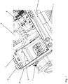
- Fig. 1 shows a frequency converter according to the invention, which is mounted on an electric motor.
- the converter housing 2 consists of a lower housing part 2a, which also has to fulfill various functional aspects, and a housing cover 2b (not shown in this drawing), which essentially only has the task of closing the converter housing 2.
- the lower housing part 2a contains a circuit carrier 4 designed as a printed circuit board, on which the electronic components 5 of the control and power electronics of the frequency converter are accommodated.
- the lower housing part 2a which is preferably made of a material with good thermal conductivity, for example aluminum, is provided on its lower outer wall with cooling fins 9, via which the heat loss resulting in particular in the power components of the frequency converter is dissipated.
- Cable glands 8 are arranged on the lateral outer walls of the lower housing part 2a, through which at least one mains connection line and further control and / or Sensor lines are routed from the outside into the interior of the converter housing 2.
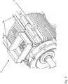
- Fig. 2 the electric motor can be seen before the assembly of the intermediate part 3, i.e. with the terminal block 7 exposed.
- the intermediate part 3 is, as in Fig. 3 can be seen, screwed directly onto the connecting piece 1a of the motor housing 1.
- the intermediate part 3 forms, on the one hand, a shaft protecting the terminal block 7 and, on the other hand, holding elements 3a provided for fastening the lower housing part 2a of the converter housing 2 to the motor housing 1.
- the lower housing part 2a is fastened to these holding elements 3a, for example by means of screws.
- the housing cover is placed on the lower housing part 2a and screwed to it to securely close the converter housing 2.
Landscapes
- Engineering & Computer Science (AREA)
- Power Engineering (AREA)
- Microelectronics & Electronic Packaging (AREA)
- Motor Or Generator Frames (AREA)
- Inverter Devices (AREA)
Description
- Die Erfindung betrifft einen Frequenzumrichter zum Steuern eines Elektromotors mit einem zur Montage auf dem Motorgehäuse vorgesehenen Umrichtergehäuse, wobei zwischen dem Motorgehäuse und dem Umrichtergehäuse ein einen Klemmenkasten ersetzendes Zwischenteil angeordnet ist, wobei das Umrichtergehäuse aus einem einen Schaltungsträger mit den elektronischen Bauelementen der Steuer- und Leistungselektronik des Frequenzumrichters aufnehmenden Gehäuseunterteil und einem Gehäusedeckel besteht, wobei das Zwischenteil Halteelemente zur mechanischen Befestigung des Gehäuseunterteils an diesem aufweist, und wobei das Gehäuseunterteil an seiner Unterseite mit einer Öffnung versehen ist.
- Frequenzumrichter der hier angesprochenen Art werden als statische Frequenzumrichter zum Betrieb von Elektromotoren, insbesondere von Synchron- und Asynchronmaschinen eingesetzt, wobei die Verbindung von Frequenzumrichter und Elektromotor zu einer baulichen Einheit hinsichtlich elektromagnetischer Störeinflüsse deutliche Vorteile gegenüber der vom Motor getrennten Aufstellung des Frequenzumrichters in einem separaten Schaltschrank hat.
- Aus der
DE 36 42 724 A1 ist es bekannt, einen Frequenzumrichter insgesamt in einem als Klemmenkasten bezeichneten Umrichtergehäuse anzuordnen. Die netzseitige Anschlussleitung des Frequenzumrichters ist als angewachsenes Kabel aus dem Umrichtergehäuse herausgeführt. Zur Verbindung der Ausgangsseite des Frequenzumrichters mit den Motorkontakten ist an dem Umrichtergehäuse ein Stutzen mit darin aufgenommenen Steckerstiften angeformt. Durch Aufstecken des Klemmenkastens auf dem Motorgehäuse werden diese Steckerstifte mit entsprechend ausgebildeten, motorseitigen Steckbuchsen kontaktiert, wobei die Steckbuchsen mit den Motoranschlussleitungen elektrisch verbunden sind. - Die
EP 0 958 646 B1 offenbart einen Frequenzumrichter bei dem zwischen dem Motorgehäuse und dem Umrichtergehäuse ein Zwischenteil angeordnet ist, das einen üblicherweise dort vorhandenen Klemmenkasten ersetzt. Das Zwischenteil bildet dabei gleichsam ein Gehäuseunterteil des Umrichtergehäuses aus, während die gesamte Elektronik des Frequenzumrichters in dem darauf zu befestigenden Gehäuseoberteil aufgenommen ist. Die elektrische Kontaktierung der Frequenzumrichter-Elektronik mit den im Zwischenteil vorhandenen Anschlusselementen erfolgt dabei über Steckverbinder. - Die
DE 10 2008 058 511 A1 offenbart einen Frequenzumrichter gemäß dem Oberbegriff des Patentanspruchs 1. Zwischen dem Motorgehäuse und dem zweiteiligen Umrichtergehäuse ist auch hier ein Zwischenteil angeordnet. Bei dem Zwischenteil werden die Motoranschlussleitungen auf den Schraubklemmen eines Klemmsteins aufgelegt, und zwar vor der Montage des Gehäuseunterteils des Umrichtergehäuses. Bei der Montage des Gehäuseunterteils auf dem Motor bzw. dem Zwischenteil werden dann einander zugeordnete Steckverbinderteile des Zwischenteils und des Umrichters miteinander in Eingriff gestellt. Dadurch werden die erforderlichen elektrischen Verbindungen zwischen dem Umrichter und dem Motor hergestellt. - Bei Elektromotoren geringer bis mittlerer Leistungsklassen und passend dazu ausgebildeten Frequenzumrichtern sind dies durchaus vorteilhafte Ausgestaltungen. Diese sind allerdings nicht mehr einsetzbar bei Frequenzumrichtern, die zum Einsatz an Elektromotoren höherer Leistung vorgesehen sind, da die hierbei verwendeten Steckverbinder bei den dann auftretenden Strömen kein geeignetes Kontaktierungsmittel mehr darstellen. Der Frequenzumrichter gemäß der vorliegenden Erfindung hat gegenüber den gezeigten, vorbekannten Lösungen den Vorteil, deutlich höhere Ströme tragen zu können, ohne dabei auf Flexibilität und Bequemlichkeit bei der Montage zu verzichten.
- Dies wird erfindungsgemäß dadurch erreicht, dass durch die Öffnung hindurch nach Befestigung des Gehäuseunterteils auf dem Zwischenteil und vor dem Aufsetzen des Gehäusedeckels ein Klemmstein des Elektromotors zum Befestigen und/oder Lösen elektrischer Anschlussleitungen an diesem von außen zugänglich ist.
- Durch den Einsatz von Schraub- oder Federklemmen anstelle von Steckkontakten zur Verbindung der Motoranschlussleitungen mit den Zuleitungen vom Schaltungsträger des Frequenzumrichters wird eine erheblich höhere Stromtragfähigkeit der elektrischen Verbindungen erreicht, so dass der erfindungsgemäße Gegenstand insbesondere für Elektromotoren höherer Leistungsklassen geeignet ist.
- Das erfindungsgemäß ausgeführte Zwischenteil ist vorzugsweise direkt auf einem Anschlussstutzen des Motorgehäuses aufgeschraubt.
- In einer bevorzugten Ausführungsform der Erfindung besteht das Gehäuseunterteil aus einem Material mit einer guten Wärmeleitfähigkeit, also z.B. aus Aluminium, und ist an seiner unteren Außenwand mit Kühlrippen versehen, so dass die insbesondere in den Leistungsbauelementen des Frequenzumrichters entstehende Verlustwärme besonders effektiv abgeführt werden kann.
- Weitere vorteilhafte Ausgestaltungen und Weiterbildungen des erfindungsgemäßen Frequenzumrichters werden anhand der Zeichnung erläutert.
- Es zeigen:
- Figur 1
- Einen erfindungsgemäßen, auf einem Motorgehäuse eines Elektromotors montierten Frequenzumrichter ohne Gehäusedeckel
- Figur 2
- Einen Elektromotor mit freiliegendem Klemmstein (ohne Klemmenkasten)
- Figur 3
- Einen Elektromotor mit einem darauf montiertem Zwischenteil zur Aufnahme des Gehäuseunterteils des Frequenzumrichters
- In
Fig. 1 ist ein erfindungsgemäßer Frequenzumrichter zu sehen, der auf einem Elektromotor montiert ist. Das Umrichtergehäuse 2 besteht dabei aus einem Gehäuseunterteil 2a, welches auch verschiedene funktionale Aspekte zu erfüllen hat, und einem (in dieser Zeichnung nicht gezeigten) Gehäusedeckel 2b, der im wesentlichen lediglich die Aufgabe hat das Umrichtergehäuse 2 zu verschließen. Das Gehäuseunterteil 2a enthält einen als Leiterplatte ausgebildeten Schaltungsträger 4, auf dem die elektronischen Bauelemente 5 der Steuer- und Leistungselektronik des Frequenzumrichters aufgenommen sind. Das Gehäuseunterteil 2a, welches bevorzugt aus einem Material mit einer guten Wärmeleitfähigkeit, also z.B. aus Aluminium besteht, ist an seiner unteren Außenwand mit Kühlrippen 9 versehen, über die die insbesondere in den Leistungsbauelementen des Frequenzumrichters entstehende Verlustwärme abgeführt wird. An den seitlichen Außenwänden des Gehäuseunterteils 2a sind Kabelverschraubungen 8 angeordnet, durch die zumindest eine Netzanschlussleitung sowie weitere Steuer- und/oder Sensorleitungen von außen in das Innere des Umrichtergehäuses 2 geführt werden. - Die mechanische Befestigung des Gehäuseunterteils 2a des Umrichtergehäuses 2 an dem Motorgehäuse 1 erfolgt mittels eines Zwischenteils 3, das zugleich die Aufgabe eines Klemmenkastens erfüllt.
- In
Fig. 2 ist der Elektromotor vor der Montage des Zwischenteils 3, also mit freiliegendem Klemmstein 7 zu sehen. Der Klemmstein 7, dessen elektrische Anschlussklemmen innerhalb des Motorgehäuses 1 mit den Anschlussleitungen des Elektromotors verbunden sind, ist auf einem Anschlussstutzen 1a des Motorgehäuses 1 angeordnet. - Das Zwischenteil 3 wird, wie in
Fig. 3 zu sehen, direkt auf dem Anschlussstutzen 1a des Motorgehäuses 1 aufgeschraubt. Das Zwischenteil 3 bildet dabei einerseits einen den Klemmstein 7 schützend umgebenden Schacht und andererseits zur Befestigung des Gehäuseunterteils 2a des Umrichtergehäuses 2 an dem Motorgehäuse 1 vorgesehene Halteelemente 3a aus. An diesen Halteelementen 3a wird das Gehäuseunterteil 2a beispielsweise mittels Schrauben befestigt. - In dem in
Fig. 1 gezeigten Zustand, in dem das Gehäuseunterteil 2a mit dem die elektronischen Bauelemente 5 der Steuer- und Leistungselektronik des Frequenzumrichters tragenden Schaltungsträger 4 auf dem Zwischenteil 3 montiert ist, ist der Klemmstein 7 des Elektromotors zur Handhabung der Anschlussleitungen bequem zugänglich, so dass die von dem Schaltungsträger 4 der Elektronik des Frequenzumrichters ausgehenden Leitungen ohne weiteres auf den Klemmen des Klemmsteins 7 je nach Ausführung desselben durch Festklemmen oder Festschrauben aufgelegt werden können. Die von außen durch die an den seitlichen Außenwänden des Gehäuseunterteils 2a vorhandenen Kabelverschraubungen 8 hindurch geführten äußeren Zuleitungen können im gleichen Arbeitsgang an dafür vorgesehenen Klemmen auf dem Schaltungsträger 4 der Elektronik des Frequenzumrichters aufgelegt werden. - Nach erfolgter interner Verdrahtung wird der Gehäusedeckel auf das Gehäuseunterteil 2a aufgesetzt und mit diesem zum sicheren Verschluss des Umrichtergehäuses 2 verschraubt.
Claims (3)
- Frequenzumrichter zum Steuern eines Elektromotors mit einem zur Montage auf dem Motorgehäuse (1) vorgesehenen Umrichtergehäuse (2), wobei zwischen dem Motorgehäuse (1) und dem Umrichtergehäuse (2) ein einen Klemmenkasten ersetzendes Zwischenteil (3) angeordnet ist, wobei das Umrichtergehäuse (2) aus einem einen Schaltungsträger (4) mit den elektronischen Bauelementen (5) der Steuer- und Leistungselektronik des Frequenzumrichters aufnehmenden Gehäuseunterteil (2a) und einem Gehäusedeckel besteht, wobei das Zwischenteil (3) Halteelemente (3a) zur mechanischen Befestigung des Gehäuseunterteils (2a) an diesem aufweist, und wobei das Gehäuseunterteil (2a) an seiner Unterseite mit einer Öffnung (6) versehen ist, dadurch gekennzeichnet, dass durch die Öffnung (6) hindurch nach Befestigung des Gehäuseunterteils (2a) auf dem Zwischenteil (3) und vor dem Aufsetzen des Gehäusedeckels ein Klemmstein (7) des Elektromotors zum Befestigen und/oder Lösen elektrischer Anschlussleitungen an diesem von außen zugänglich ist.
- Frequenzumrichter nach Anspruch 1, dadurch gekennzeichnet, dass das Zwischenteil (3) direkt auf einem Anschlussstutzen (1a) des Motorgehäuses (1) aufgeschraubt ist.
- Frequenzumrichter nach Anspruch 1 oder 2, dadurch gekennzeichnet, dass das Gehäuseunterteil (2a) aus einem Material mit einer guten Wärmeleitfähigkeit besteht und an seiner unteren Außenwand mit Kühlrippen (9) versehen ist.
Applications Claiming Priority (1)
| Application Number | Priority Date | Filing Date | Title |
|---|---|---|---|
| DE102010051891A DE102010051891A1 (de) | 2010-11-22 | 2010-11-22 | Frequenzumrichter zum Steuern eines Elektromotors |
Publications (3)
| Publication Number | Publication Date |
|---|---|
| EP2456051A2 EP2456051A2 (de) | 2012-05-23 |
| EP2456051A3 EP2456051A3 (de) | 2016-11-09 |
| EP2456051B1 true EP2456051B1 (de) | 2020-08-12 |
Family
ID=45421826
Family Applications (1)
| Application Number | Title | Priority Date | Filing Date |
|---|---|---|---|
| EP11189398.8A Active EP2456051B1 (de) | 2010-11-22 | 2011-11-16 | Frequenzumrichter zum Steuern eines Elektromotors |
Country Status (3)
| Country | Link |
|---|---|
| US (1) | US8810090B2 (de) |
| EP (1) | EP2456051B1 (de) |
| DE (1) | DE102010051891A1 (de) |
Families Citing this family (6)
| Publication number | Priority date | Publication date | Assignee | Title |
|---|---|---|---|---|
| JP6261462B2 (ja) * | 2014-06-27 | 2018-01-17 | ミネベアミツミ株式会社 | レゾルバおよびその端子台構造ならびにモータの回転角度の検出センサ |
| DE102015119002A1 (de) * | 2015-11-05 | 2017-05-11 | Ebm-Papst Mulfingen Gmbh & Co. Kg | Elektronikeinheit |
| CN107579626B (zh) * | 2017-10-23 | 2025-01-28 | 江苏瑞斯曼节能技术有限公司 | 永磁电机节能系统及水泵、风机、压缩机 |
| US11705774B2 (en) * | 2018-12-27 | 2023-07-18 | Abb Schweiz Ag | Industrial electrical machine system and electronics module |
| AT523611B1 (de) * | 2020-03-05 | 2021-12-15 | Avl List Gmbh | Schaltschrank für eine elektrische Umrichterbaugruppe |
| CN112332743A (zh) * | 2020-11-16 | 2021-02-05 | 青岛中加特电气股份有限公司 | 一种变频一体机 |
Family Cites Families (10)
| Publication number | Priority date | Publication date | Assignee | Title |
|---|---|---|---|---|
| US4451750A (en) * | 1981-02-03 | 1984-05-29 | Elektro-Mechanik Gmbh | Protective arrangement for a plug-connected electric motor sealed against pressure, vapors and radiation |
| DE3642724A1 (de) | 1986-12-13 | 1988-06-23 | Grundfos Int | Elektromotor mit einem frequenzumrichter zur steuerung der motorbetriebsgroessen |
| DE19704226B4 (de) * | 1997-02-05 | 2004-09-30 | Sew-Eurodrive Gmbh & Co. Kg | Klemmdeckelumrichter |
| DE19926542B4 (de) * | 1999-06-10 | 2016-06-09 | Sew-Eurodrive Gmbh & Co Kg | Steckverbindereinheit für einen Anschlußkasten eines Elektromotors |
| DE10109797B4 (de) * | 2001-03-01 | 2019-03-21 | Sew-Eurodrive Gmbh & Co Kg | Umrichtermotor, umfassend einen Motor, mindestens ein Zwischenteil und einen Umrichter |
| JP4161074B2 (ja) * | 2004-02-02 | 2008-10-08 | 三菱電機株式会社 | 電動式パワーステアリング装置 |
| DE102006016271B4 (de) * | 2005-04-12 | 2022-11-10 | Sew-Eurodrive Gmbh & Co Kg | Verfahren zum Herstellen eines Elektromotors |
| DE202007016431U1 (de) * | 2007-11-14 | 2008-02-21 | Vem Motors Gmbh | Adapterplatte für eine rotierende elektrische Maschine mit einem Gussgehäuse |
| EP2110929B1 (de) * | 2008-04-18 | 2018-08-29 | Grundfos Management a/s | Frequenzumrichter auf einem Motor |
| DE102008058511A1 (de) * | 2008-11-21 | 2010-05-27 | Kostal Industrie Elektrik Gmbh | Frequenzumrichter zum Steuern eines Elektromotors |
-
2010
- 2010-11-22 DE DE102010051891A patent/DE102010051891A1/de not_active Withdrawn
-
2011
- 2011-10-26 US US13/282,003 patent/US8810090B2/en active Active
- 2011-11-16 EP EP11189398.8A patent/EP2456051B1/de active Active
Non-Patent Citations (1)
| Title |
|---|
| None * |
Also Published As
| Publication number | Publication date |
|---|---|
| US20120126645A1 (en) | 2012-05-24 |
| EP2456051A2 (de) | 2012-05-23 |
| US8810090B2 (en) | 2014-08-19 |
| EP2456051A3 (de) | 2016-11-09 |
| DE102010051891A1 (de) | 2012-05-24 |
Similar Documents
| Publication | Publication Date | Title |
|---|---|---|
| EP2190105B1 (de) | Frequenzumrichter zum Steuern eines Elektromotors | |
| EP3066902B1 (de) | Funktionskomponentenoberteil für ein komponentenaufbausystem | |
| DE112014001150B4 (de) | Wechselrichtersubstrat und Wechselrichter enthaltender elektrischer Kompressor, der dieses verwendet | |
| DE19926542B4 (de) | Steckverbindereinheit für einen Anschlußkasten eines Elektromotors | |
| DE19905952C2 (de) | Verteilerkasten | |
| US20120268864A1 (en) | Apparatus having plurality of openings to access removable electronic devices some of which have electrical connections using no circuit board trace | |
| EP2456051A2 (de) | Frequenzumrichter zum Steuern eines Elektromotors | |
| EP3673567B1 (de) | Anschlussvorrichtung und elektromotor | |
| EP1254500A1 (de) | Elektrische antriebseinheit aus elektromotor und elektronikmodul | |
| EP2645504A2 (de) | Anschlussdose | |
| DE102017208632A1 (de) | Kraftfahrzeug und Stromrichtereinrichtung für ein Kraftfahrzeug | |
| DE102008022056B4 (de) | Anschlussdose, insbesondere für Solarmodule | |
| EP2277238A1 (de) | Toleranzausgleichender, elektrischer verbinder, insbesondere für kraftfahrzeugsteuergeräte | |
| EP1779496B1 (de) | Anschlussvorrichtung für eine elektrische maschine | |
| DE112014000405T5 (de) | Elektrischer Kompressor mit integriertem Wechselrichter | |
| EP3171487B1 (de) | Antriebssystem und hybridsteckersystem für ein antriebssystem | |
| EP2359439A1 (de) | Anschluss-system zur realisierung von abzweigungen an durchgehenden leitern | |
| DE202008013992U1 (de) | Modulare Montagebasis für elektrische Geräte | |
| DE10340297B4 (de) | Verbindugsanordnung zur Verbindung von aktiven und passiven elektrischen und elektronischen Bauelementen | |
| WO2014161828A1 (de) | Wechselrichter und gleichstromanschlusseinheit für einen wechselrichter | |
| DE102010029374A1 (de) | Leistungselektronikanordnung | |
| DE102013007815B4 (de) | Schwenkbarer Verbinder und Kontaktierungsverfahren | |
| DE9106789U1 (de) | Steckmodul für Leuchten mit Schutzkleinspannung | |
| WO2009043535A1 (de) | Haltevorrichtung für eine kreiselpumpenanordnung | |
| WO2009103447A1 (de) | Verfahren zur aufnahme eines elektrischen/elektronischen bauteils und entsprechendes montageverfahren sowie abdeckung für eine solche vorrichtung |
Legal Events
| Date | Code | Title | Description |
|---|---|---|---|
| PUAI | Public reference made under article 153(3) epc to a published international application that has entered the european phase |
Free format text: ORIGINAL CODE: 0009012 |
|
| AK | Designated contracting states |
Kind code of ref document: A2 Designated state(s): AL AT BE BG CH CY CZ DE DK EE ES FI FR GB GR HR HU IE IS IT LI LT LU LV MC MK MT NL NO PL PT RO RS SE SI SK SM TR |
|
| AX | Request for extension of the european patent |
Extension state: BA ME |
|
| PUAL | Search report despatched |
Free format text: ORIGINAL CODE: 0009013 |
|
| AK | Designated contracting states |
Kind code of ref document: A3 Designated state(s): AL AT BE BG CH CY CZ DE DK EE ES FI FR GB GR HR HU IE IS IT LI LT LU LV MC MK MT NL NO PL PT RO RS SE SI SK SM TR |
|
| AX | Request for extension of the european patent |
Extension state: BA ME |
|
| RIC1 | Information provided on ipc code assigned before grant |
Ipc: H02M 7/00 20060101ALN20161004BHEP Ipc: H02K 5/22 20060101AFI20161004BHEP Ipc: H02K 11/00 20160101ALI20161004BHEP |
|
| STAA | Information on the status of an ep patent application or granted ep patent |
Free format text: STATUS: REQUEST FOR EXAMINATION WAS MADE |
|
| 17P | Request for examination filed |
Effective date: 20170427 |
|
| RBV | Designated contracting states (corrected) |
Designated state(s): AL AT BE BG CH CY CZ DE DK EE ES FI FR GB GR HR HU IE IS IT LI LT LU LV MC MK MT NL NO PL PT RO RS SE SI SK SM TR |
|
| GRAP | Despatch of communication of intention to grant a patent |
Free format text: ORIGINAL CODE: EPIDOSNIGR1 |
|
| STAA | Information on the status of an ep patent application or granted ep patent |
Free format text: STATUS: GRANT OF PATENT IS INTENDED |
|
| RIC1 | Information provided on ipc code assigned before grant |
Ipc: H02M 7/00 20060101ALN20200302BHEP Ipc: H02K 5/22 20060101AFI20200302BHEP Ipc: H02K 11/00 20160101ALI20200302BHEP |
|
| INTG | Intention to grant announced |
Effective date: 20200325 |
|
| GRAS | Grant fee paid |
Free format text: ORIGINAL CODE: EPIDOSNIGR3 |
|
| GRAA | (expected) grant |
Free format text: ORIGINAL CODE: 0009210 |
|
| STAA | Information on the status of an ep patent application or granted ep patent |
Free format text: STATUS: THE PATENT HAS BEEN GRANTED |
|
| AK | Designated contracting states |
Kind code of ref document: B1 Designated state(s): AL AT BE BG CH CY CZ DE DK EE ES FI FR GB GR HR HU IE IS IT LI LT LU LV MC MK MT NL NO PL PT RO RS SE SI SK SM TR |
|
| REG | Reference to a national code |
Ref country code: GB Ref legal event code: FG4D Free format text: NOT ENGLISH |
|
| REG | Reference to a national code |
Ref country code: CH Ref legal event code: EP |
|
| REG | Reference to a national code |
Ref country code: DE Ref legal event code: R096 Ref document number: 502011016860 Country of ref document: DE |
|
| REG | Reference to a national code |
Ref country code: IE Ref legal event code: FG4D Free format text: LANGUAGE OF EP DOCUMENT: GERMAN |
|
| REG | Reference to a national code |
Ref country code: AT Ref legal event code: REF Ref document number: 1302520 Country of ref document: AT Kind code of ref document: T Effective date: 20200915 |
|
| REG | Reference to a national code |
Ref country code: LT Ref legal event code: MG4D |
|
| REG | Reference to a national code |
Ref country code: NL Ref legal event code: MP Effective date: 20200812 |
|
| PG25 | Lapsed in a contracting state [announced via postgrant information from national office to epo] |
Ref country code: NO Free format text: LAPSE BECAUSE OF FAILURE TO SUBMIT A TRANSLATION OF THE DESCRIPTION OR TO PAY THE FEE WITHIN THE PRESCRIBED TIME-LIMIT Effective date: 20201112 Ref country code: BG Free format text: LAPSE BECAUSE OF FAILURE TO SUBMIT A TRANSLATION OF THE DESCRIPTION OR TO PAY THE FEE WITHIN THE PRESCRIBED TIME-LIMIT Effective date: 20201112 Ref country code: SE Free format text: LAPSE BECAUSE OF FAILURE TO SUBMIT A TRANSLATION OF THE DESCRIPTION OR TO PAY THE FEE WITHIN THE PRESCRIBED TIME-LIMIT Effective date: 20200812 Ref country code: HR Free format text: LAPSE BECAUSE OF FAILURE TO SUBMIT A TRANSLATION OF THE DESCRIPTION OR TO PAY THE FEE WITHIN THE PRESCRIBED TIME-LIMIT Effective date: 20200812 Ref country code: LT Free format text: LAPSE BECAUSE OF FAILURE TO SUBMIT A TRANSLATION OF THE DESCRIPTION OR TO PAY THE FEE WITHIN THE PRESCRIBED TIME-LIMIT Effective date: 20200812 Ref country code: ES Free format text: LAPSE BECAUSE OF FAILURE TO SUBMIT A TRANSLATION OF THE DESCRIPTION OR TO PAY THE FEE WITHIN THE PRESCRIBED TIME-LIMIT Effective date: 20200812 Ref country code: FI Free format text: LAPSE BECAUSE OF FAILURE TO SUBMIT A TRANSLATION OF THE DESCRIPTION OR TO PAY THE FEE WITHIN THE PRESCRIBED TIME-LIMIT Effective date: 20200812 Ref country code: GR Free format text: LAPSE BECAUSE OF FAILURE TO SUBMIT A TRANSLATION OF THE DESCRIPTION OR TO PAY THE FEE WITHIN THE PRESCRIBED TIME-LIMIT Effective date: 20201113 |
|
| PG25 | Lapsed in a contracting state [announced via postgrant information from national office to epo] |
Ref country code: LV Free format text: LAPSE BECAUSE OF FAILURE TO SUBMIT A TRANSLATION OF THE DESCRIPTION OR TO PAY THE FEE WITHIN THE PRESCRIBED TIME-LIMIT Effective date: 20200812 Ref country code: RS Free format text: LAPSE BECAUSE OF FAILURE TO SUBMIT A TRANSLATION OF THE DESCRIPTION OR TO PAY THE FEE WITHIN THE PRESCRIBED TIME-LIMIT Effective date: 20200812 Ref country code: NL Free format text: LAPSE BECAUSE OF FAILURE TO SUBMIT A TRANSLATION OF THE DESCRIPTION OR TO PAY THE FEE WITHIN THE PRESCRIBED TIME-LIMIT Effective date: 20200812 Ref country code: PL Free format text: LAPSE BECAUSE OF FAILURE TO SUBMIT A TRANSLATION OF THE DESCRIPTION OR TO PAY THE FEE WITHIN THE PRESCRIBED TIME-LIMIT Effective date: 20200812 Ref country code: IS Free format text: LAPSE BECAUSE OF FAILURE TO SUBMIT A TRANSLATION OF THE DESCRIPTION OR TO PAY THE FEE WITHIN THE PRESCRIBED TIME-LIMIT Effective date: 20201212 |
|
| PG25 | Lapsed in a contracting state [announced via postgrant information from national office to epo] |
Ref country code: EE Free format text: LAPSE BECAUSE OF FAILURE TO SUBMIT A TRANSLATION OF THE DESCRIPTION OR TO PAY THE FEE WITHIN THE PRESCRIBED TIME-LIMIT Effective date: 20200812 Ref country code: CZ Free format text: LAPSE BECAUSE OF FAILURE TO SUBMIT A TRANSLATION OF THE DESCRIPTION OR TO PAY THE FEE WITHIN THE PRESCRIBED TIME-LIMIT Effective date: 20200812 Ref country code: DK Free format text: LAPSE BECAUSE OF FAILURE TO SUBMIT A TRANSLATION OF THE DESCRIPTION OR TO PAY THE FEE WITHIN THE PRESCRIBED TIME-LIMIT Effective date: 20200812 Ref country code: RO Free format text: LAPSE BECAUSE OF FAILURE TO SUBMIT A TRANSLATION OF THE DESCRIPTION OR TO PAY THE FEE WITHIN THE PRESCRIBED TIME-LIMIT Effective date: 20200812 Ref country code: SM Free format text: LAPSE BECAUSE OF FAILURE TO SUBMIT A TRANSLATION OF THE DESCRIPTION OR TO PAY THE FEE WITHIN THE PRESCRIBED TIME-LIMIT Effective date: 20200812 |
|
| REG | Reference to a national code |
Ref country code: DE Ref legal event code: R097 Ref document number: 502011016860 Country of ref document: DE |
|
| PG25 | Lapsed in a contracting state [announced via postgrant information from national office to epo] |
Ref country code: AL Free format text: LAPSE BECAUSE OF FAILURE TO SUBMIT A TRANSLATION OF THE DESCRIPTION OR TO PAY THE FEE WITHIN THE PRESCRIBED TIME-LIMIT Effective date: 20200812 |
|
| PLBE | No opposition filed within time limit |
Free format text: ORIGINAL CODE: 0009261 |
|
| STAA | Information on the status of an ep patent application or granted ep patent |
Free format text: STATUS: NO OPPOSITION FILED WITHIN TIME LIMIT |
|
| PG25 | Lapsed in a contracting state [announced via postgrant information from national office to epo] |
Ref country code: SK Free format text: LAPSE BECAUSE OF FAILURE TO SUBMIT A TRANSLATION OF THE DESCRIPTION OR TO PAY THE FEE WITHIN THE PRESCRIBED TIME-LIMIT Effective date: 20200812 Ref country code: MC Free format text: LAPSE BECAUSE OF FAILURE TO SUBMIT A TRANSLATION OF THE DESCRIPTION OR TO PAY THE FEE WITHIN THE PRESCRIBED TIME-LIMIT Effective date: 20200812 |
|
| REG | Reference to a national code |
Ref country code: CH Ref legal event code: PL |
|
| 26N | No opposition filed |
Effective date: 20210514 |
|
| PG25 | Lapsed in a contracting state [announced via postgrant information from national office to epo] |
Ref country code: LU Free format text: LAPSE BECAUSE OF NON-PAYMENT OF DUE FEES Effective date: 20201116 Ref country code: IT Free format text: LAPSE BECAUSE OF FAILURE TO SUBMIT A TRANSLATION OF THE DESCRIPTION OR TO PAY THE FEE WITHIN THE PRESCRIBED TIME-LIMIT Effective date: 20200812 |
|
| REG | Reference to a national code |
Ref country code: BE Ref legal event code: MM Effective date: 20201130 |
|
| PG25 | Lapsed in a contracting state [announced via postgrant information from national office to epo] |
Ref country code: CH Free format text: LAPSE BECAUSE OF NON-PAYMENT OF DUE FEES Effective date: 20201130 Ref country code: LI Free format text: LAPSE BECAUSE OF NON-PAYMENT OF DUE FEES Effective date: 20201130 Ref country code: SI Free format text: LAPSE BECAUSE OF FAILURE TO SUBMIT A TRANSLATION OF THE DESCRIPTION OR TO PAY THE FEE WITHIN THE PRESCRIBED TIME-LIMIT Effective date: 20200812 |
|
| PG25 | Lapsed in a contracting state [announced via postgrant information from national office to epo] |
Ref country code: IE Free format text: LAPSE BECAUSE OF NON-PAYMENT OF DUE FEES Effective date: 20201116 |
|
| REG | Reference to a national code |
Ref country code: AT Ref legal event code: MM01 Ref document number: 1302520 Country of ref document: AT Kind code of ref document: T Effective date: 20201116 |
|
| PG25 | Lapsed in a contracting state [announced via postgrant information from national office to epo] |
Ref country code: AT Free format text: LAPSE BECAUSE OF NON-PAYMENT OF DUE FEES Effective date: 20201116 |
|
| PG25 | Lapsed in a contracting state [announced via postgrant information from national office to epo] |
Ref country code: TR Free format text: LAPSE BECAUSE OF FAILURE TO SUBMIT A TRANSLATION OF THE DESCRIPTION OR TO PAY THE FEE WITHIN THE PRESCRIBED TIME-LIMIT Effective date: 20200812 Ref country code: MT Free format text: LAPSE BECAUSE OF FAILURE TO SUBMIT A TRANSLATION OF THE DESCRIPTION OR TO PAY THE FEE WITHIN THE PRESCRIBED TIME-LIMIT Effective date: 20200812 Ref country code: CY Free format text: LAPSE BECAUSE OF FAILURE TO SUBMIT A TRANSLATION OF THE DESCRIPTION OR TO PAY THE FEE WITHIN THE PRESCRIBED TIME-LIMIT Effective date: 20200812 |
|
| PG25 | Lapsed in a contracting state [announced via postgrant information from national office to epo] |
Ref country code: MK Free format text: LAPSE BECAUSE OF FAILURE TO SUBMIT A TRANSLATION OF THE DESCRIPTION OR TO PAY THE FEE WITHIN THE PRESCRIBED TIME-LIMIT Effective date: 20200812 |
|
| PG25 | Lapsed in a contracting state [announced via postgrant information from national office to epo] |
Ref country code: PT Free format text: LAPSE BECAUSE OF FAILURE TO SUBMIT A TRANSLATION OF THE DESCRIPTION OR TO PAY THE FEE WITHIN THE PRESCRIBED TIME-LIMIT Effective date: 20200812 Ref country code: BE Free format text: LAPSE BECAUSE OF NON-PAYMENT OF DUE FEES Effective date: 20201130 |
|
| PGFP | Annual fee paid to national office [announced via postgrant information from national office to epo] |
Ref country code: GB Payment date: 20231102 Year of fee payment: 13 |
|
| REG | Reference to a national code |
Ref country code: DE Ref legal event code: R081 Ref document number: 502011016860 Country of ref document: DE Owner name: KOSTAL INDUSTRIE ELEKTRIK GMBH & CO. KG, DE Free format text: FORMER OWNER: KOSTAL INDUSTRIE ELEKTRIK GMBH, 58513 LUEDENSCHEID, DE |
|
| PGFP | Annual fee paid to national office [announced via postgrant information from national office to epo] |
Ref country code: DE Payment date: 20241029 Year of fee payment: 14 |
|
| PGFP | Annual fee paid to national office [announced via postgrant information from national office to epo] |
Ref country code: FR Payment date: 20241129 Year of fee payment: 14 |
|
| GBPC | Gb: european patent ceased through non-payment of renewal fee |
Effective date: 20241116 |
|
| PG25 | Lapsed in a contracting state [announced via postgrant information from national office to epo] |
Ref country code: GB Free format text: LAPSE BECAUSE OF NON-PAYMENT OF DUE FEES Effective date: 20241116 |