EP2456045A1 - Method and apparatus for transmitting power and data without contact - Google Patents
Method and apparatus for transmitting power and data without contact Download PDFInfo
- Publication number
- EP2456045A1 EP2456045A1 EP10799722A EP10799722A EP2456045A1 EP 2456045 A1 EP2456045 A1 EP 2456045A1 EP 10799722 A EP10799722 A EP 10799722A EP 10799722 A EP10799722 A EP 10799722A EP 2456045 A1 EP2456045 A1 EP 2456045A1
- Authority
- EP
- European Patent Office
- Prior art keywords
- coil
- power
- transmission coil
- information transmission
- power transmission
- Prior art date
- Legal status (The legal status is an assumption and is not a legal conclusion. Google has not performed a legal analysis and makes no representation as to the accuracy of the status listed.)
- Granted
Links
Images


Classifications
-
- H—ELECTRICITY
- H02—GENERATION; CONVERSION OR DISTRIBUTION OF ELECTRIC POWER
- H02J—ELECTRIC POWER NETWORKS; CIRCUIT ARRANGEMENTS OR SYSTEMS FOR SUPPLYING OR DISTRIBUTING ELECTRIC POWER; SYSTEMS FOR STORING ELECTRIC ENERGY
- H02J50/00—Circuit arrangements or systems for wireless supply or distribution of electric power
- H02J50/70—Circuit arrangements or systems for wireless supply or distribution of electric power involving the reduction of electric, magnetic or electromagnetic leakage fields
-
- H—ELECTRICITY
- H01—ELECTRIC ELEMENTS
- H01F—MAGNETS; INDUCTANCES; TRANSFORMERS; SELECTION OF MATERIALS FOR THEIR MAGNETIC PROPERTIES
- H01F27/00—Details of transformers or inductances, in general
- H01F27/34—Special means for preventing or reducing unwanted electric or magnetic effects, e.g. no-load losses, reactive currents, harmonics, oscillations, leakage fields
- H01F27/36—Electric or magnetic shields or screens
-
- H—ELECTRICITY
- H01—ELECTRIC ELEMENTS
- H01F—MAGNETS; INDUCTANCES; TRANSFORMERS; SELECTION OF MATERIALS FOR THEIR MAGNETIC PROPERTIES
- H01F27/00—Details of transformers or inductances, in general
- H01F27/34—Special means for preventing or reducing unwanted electric or magnetic effects, e.g. no-load losses, reactive currents, harmonics, oscillations, leakage fields
- H01F27/36—Electric or magnetic shields or screens
- H01F27/366—Electric or magnetic shields or screens made of ferromagnetic material
-
- H—ELECTRICITY
- H01—ELECTRIC ELEMENTS
- H01F—MAGNETS; INDUCTANCES; TRANSFORMERS; SELECTION OF MATERIALS FOR THEIR MAGNETIC PROPERTIES
- H01F38/00—Adaptations of transformers or inductances for specific applications or functions
- H01F38/14—Inductive couplings
-
- H—ELECTRICITY
- H02—GENERATION; CONVERSION OR DISTRIBUTION OF ELECTRIC POWER
- H02J—ELECTRIC POWER NETWORKS; CIRCUIT ARRANGEMENTS OR SYSTEMS FOR SUPPLYING OR DISTRIBUTING ELECTRIC POWER; SYSTEMS FOR STORING ELECTRIC ENERGY
- H02J50/00—Circuit arrangements or systems for wireless supply or distribution of electric power
- H02J50/10—Circuit arrangements or systems for wireless supply or distribution of electric power using inductive coupling
-
- H—ELECTRICITY
- H02—GENERATION; CONVERSION OR DISTRIBUTION OF ELECTRIC POWER
- H02J—ELECTRIC POWER NETWORKS; CIRCUIT ARRANGEMENTS OR SYSTEMS FOR SUPPLYING OR DISTRIBUTING ELECTRIC POWER; SYSTEMS FOR STORING ELECTRIC ENERGY
- H02J50/00—Circuit arrangements or systems for wireless supply or distribution of electric power
- H02J50/10—Circuit arrangements or systems for wireless supply or distribution of electric power using inductive coupling
- H02J50/12—Circuit arrangements or systems for wireless supply or distribution of electric power using inductive coupling of the resonant type
-
- H—ELECTRICITY
- H02—GENERATION; CONVERSION OR DISTRIBUTION OF ELECTRIC POWER
- H02J—ELECTRIC POWER NETWORKS; CIRCUIT ARRANGEMENTS OR SYSTEMS FOR SUPPLYING OR DISTRIBUTING ELECTRIC POWER; SYSTEMS FOR STORING ELECTRIC ENERGY
- H02J7/00—Circuit arrangements for charging or discharging batteries or for supplying loads from batteries
- H02J7/40—Circuit arrangements for charging or discharging batteries or for supplying loads from batteries characterised by the exchange of charge or discharge related data
- H02J7/42—Circuit arrangements for charging or discharging batteries or for supplying loads from batteries characterised by the exchange of charge or discharge related data with electronic devices having internal batteries, e.g. mobile phones
-
- H—ELECTRICITY
- H04—ELECTRIC COMMUNICATION TECHNIQUE
- H04B—TRANSMISSION
- H04B5/00—Near-field transmission systems, e.g. inductive or capacitive transmission systems
- H04B5/20—Near-field transmission systems, e.g. inductive or capacitive transmission systems characterised by the transmission technique; characterised by the transmission medium
- H04B5/24—Inductive coupling
- H04B5/26—Inductive coupling using coils
-
- H—ELECTRICITY
- H04—ELECTRIC COMMUNICATION TECHNIQUE
- H04B—TRANSMISSION
- H04B5/00—Near-field transmission systems, e.g. inductive or capacitive transmission systems
- H04B5/20—Near-field transmission systems, e.g. inductive or capacitive transmission systems characterised by the transmission technique; characterised by the transmission medium
- H04B5/24—Inductive coupling
- H04B5/26—Inductive coupling using coils
- H04B5/263—Multiple coils at either side
-
- H—ELECTRICITY
- H04—ELECTRIC COMMUNICATION TECHNIQUE
- H04B—TRANSMISSION
- H04B5/00—Near-field transmission systems, e.g. inductive or capacitive transmission systems
- H04B5/20—Near-field transmission systems, e.g. inductive or capacitive transmission systems characterised by the transmission technique; characterised by the transmission medium
- H04B5/24—Inductive coupling
- H04B5/26—Inductive coupling using coils
- H04B5/266—One coil at each side, e.g. with primary and secondary coils
-
- H—ELECTRICITY
- H04—ELECTRIC COMMUNICATION TECHNIQUE
- H04B—TRANSMISSION
- H04B5/00—Near-field transmission systems, e.g. inductive or capacitive transmission systems
- H04B5/70—Near-field transmission systems, e.g. inductive or capacitive transmission systems specially adapted for specific purposes
- H04B5/79—Near-field transmission systems, e.g. inductive or capacitive transmission systems specially adapted for specific purposes for data transfer in combination with power transfer
Definitions
- the present invention relates to a method of contactlessly transmitting power and data, and an apparatus therefor, and more particularly to a contactless power and data transmission apparatus using a planar coil in which a coil is planarly wound.
- Patent Literature 1 a contactless power transmission system (Patent Literature 1) in which a power transmission is performed in a non-contact (contactless) manner
- Patent Literature 2 a data transfer circuit (Patent Literature 2) in which a data transmission is performed in a non-contact (contactless) manner have been proposed.
- a pair of coils are opposingly placed, and power is supplied to or data is transmitted to or received from a secondary apparatus by means of electromagnetic induction between the pair of coils.
- a power transmission coil (51) has a structure where a shield is placed outside a power transmission/reception coil, and, as shown in Fig. 4A , magnetic fluxes (M) at that time are generated in parallel to the surface of the coil without leaking to the outside of the shield.
- an information transmission coil (52) and the power transmission coil (51) may be contemplated to be placed on concentric circles as shown in Fig. 4B .
- the density of magnetic fluxes generated by the power transmission coil (51) is high, and also the information transmission coil (52) is in a positional relationship in which the coil receives the generated magnetic fluxes (M) in an optimum direction as shown in Fig. 4C . Therefore, a large electromotive force (F) is generated, and has a large influence on transmission/reception signals for information transmission which is the original purpose, so that a sufficient S/N ratio cannot be obtained. Consequently, the system is not adequate for information transmission.
- a signal of the information transmission coil i.e., the magnetic fluxes (M) are converted to an electromotive force of the power transmission coil (51), and most of the energy is absorbed to increase the loss, so that the system is impractical.
- the invention is characterized in that a pair of coil units are magnetically coupled to each other, each of the coil units having: a power transmission coil configured by a coil which is wound in a plane, and a magnetic shield member which is placed on a rear surface of the coil; and an information transmission coil configured by a coil which is wound in a plane, and a magnetic shield member which is placed on a rear surface of the coil, the information transmission coil and the power transmission coil being stacked in a state where the information transmission coil is positioned in a coil outer circumferential portion of the power transmission coil, and data are transmitted while power is transmitted.
- the coil diameter of the information transmission coil is formed to be smaller than that of the power transmission coil, and magnetic fields are superimposed by stackingly placing the information transmission coil while being positioned in the coil outer circumferential portion of the power transmission coil.
- the direction of the magnetic fluxes of the power transmission coil pass through the information transmission coil, therefore, the positional relationship in which an electrical offset is performed is obtained, and hence substantially little electromotive force is generated.
- the magnetic fluxes generated by the information transmission coil are in a direction along which the fluxes are hardly absorbed by the power transmission coil, and hence the loss can be reduced.
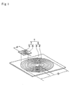
- the coil unit (1) is configured by stackingly placing an information transmission coil (7) in which a rectangular magnetic shield member (6) is placed on the rear surface side of a coil (5) that is planarly wound, on an upper surface portion of a power transmission coil (4) in which a rectangular magnetic shield member (3) is placed on the rear surface side of a coil (2) that is planarly wound.
- the coil diameter (d) of the information transmission coil (7) is formed to be smaller than the coil diameter (D) of the power transmission coil (4), and the information transmission coil (7) is placed in a portion which is close to the outer circumference of the power transmission coil (4).
- a pair of coil units (1) which are configured as described above are opposingly placed, one of the coil units is set as a primary coil (power-transmission side coil), the other coil unit is set as a secondary coil (power-reception side coil), and electromagnetic induction is produced between the coils, whereby power and information supplied to the primary coil are transmitted to the secondary coil.
- the power transmission coil (4) and the information transmission coil (7) may be configured by forming a printed wiring on a laminated circuit board, by spirally winding a single-core lead wire, or by spirally winding a Litz wire.
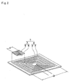
- FIG. 2 An embodiment shown in Fig. 2 has the same configuration as the above-described embodiment except that the coils (2), (5) for the power transmission coil (4) and information transmission coil (7) constituting the coil unit (1) are planarly wound so as to be formed into a substantially rectangular shape.
- the electromotive force generated in the information transmission coil (7) was measured in a case where a circular coil having a diameter of 45 mm was used as the power transmission coil (4), a circular coil having a diameter of 15 mm was used as the information transmission coil (7), and the power transmission coil (51) and information transmission coil (52) shown in Fig. 4B were placed on concentric circles, and also in a case where the information transmission coil (7) was placed in an outer circumferential portion of the power transmission coil (4) shown in Fig. 1 .
- the electromotive force which was generated in the case where the power transmission coils (4), (51) and the information transmission coils (7), (52) were placed on concentric circles was 30 mV.
- the electromotive force in the case where the information transmission coils (7), (52) were placed in outer circumferential portions of the power transmission coils (4), (51) was 1 mV. Furthermore, when the centers of the information transmission coils (7), (52) are placed in outer circumferential portions of the power transmission coils (4), (51), the electromotive force is reduced to 0.001 mV.
- the positions of the information transmission coils (7), (52) are preferably those where magnetic fluxes in the opposite direction do not pass, and, as the outer circumferential edges of the information transmission coils are remoter from the centers of the power transmission coils (4), (51), the information transmission coils are less susceptible to the magnetic fluxes.
- a practical position is considered to be preferably at a position where the outer circumferential edges of the both coils overlap with each other. Then, the electromotive force is sufficiently suppressed at a position where the outer circumferential edges of the both coils overlap with each other, and the position is a position suitable for information conveyance.
- the above embodiments have been described with respect to the configuration where the magnetic shield members are formed into a square shape.
- the shield members may have an oblong rectangular shape according to the shape of the apparatus functioning as the secondary.
- the shape of each coil may be an oblong rectangular shape or an oblong circular shape.
- the coil shape may be that according to the shape of the magnetic shield member, and, for example, rhombic, polygonal, circular, or oval.
Landscapes
- Engineering & Computer Science (AREA)
- Power Engineering (AREA)
- Computer Networks & Wireless Communication (AREA)
- Signal Processing (AREA)
- Physics & Mathematics (AREA)
- Electromagnetism (AREA)
- Near-Field Transmission Systems (AREA)
Abstract
Description
- The present invention relates to a method of contactlessly transmitting power and data, and an apparatus therefor, and more particularly to a contactless power and data transmission apparatus using a planar coil in which a coil is planarly wound.
- Although recently a wireless transmission such as UWB (ultrawideband wireless) has been advanced, it is impossible in principle to perform a wireless power transmission. Therefore, an apparatus of the type in which power and information are simultaneously transmitted in a non-contact manner is hardly produced.
- On the other hand, a contactless power transmission system (Patent Literature 1) in which a power transmission is performed in a non-contact (contactless) manner, and a data transfer circuit (Patent Literature 2) in which a data transmission is performed in a non-contact (contactless) manner have been proposed.
- In these conventional contactless power transmission system and data transfer circuit, a pair of coils are opposingly placed, and power is supplied to or data is transmitted to or received from a secondary apparatus by means of electromagnetic induction between the pair of coils.
-
- Patent Literature 1: Japanese Patent Application Laid-Open No.
2006-230032 - Patent Literature 2: Japanese Patent Application Laid-Open No.
2006-157230 - In a system such as that of
Patent Literature 1, usually, a power transmission coil (51) has a structure where a shield is placed outside a power transmission/reception coil, and, as shown inFig. 4A , magnetic fluxes (M) at that time are generated in parallel to the surface of the coil without leaking to the outside of the shield. - Then, with respect to the positional relationship between an information transmission coil (52) and the power transmission coil (51), they may be contemplated to be placed on concentric circles as shown in
Fig. 4B . In such a placement, the density of magnetic fluxes generated by the power transmission coil (51) is high, and also the information transmission coil (52) is in a positional relationship in which the coil receives the generated magnetic fluxes (M) in an optimum direction as shown inFig. 4C . Therefore, a large electromotive force (F) is generated, and has a large influence on transmission/reception signals for information transmission which is the original purpose, so that a sufficient S/N ratio cannot be obtained.
Consequently, the system is not adequate for information transmission. In the positional relationship, moreover, a signal of the information transmission coil, i.e., the magnetic fluxes (M) are converted to an electromotive force of the power transmission coil (51), and most of the energy is absorbed to increase the loss, so that the system is impractical. - As described above, in each of conventional noncontact power transmission system and data transfer circuit, power or information can be individually conveyed by means of electromagnetic induction produced between the pair of coils, but information and power cannot be simultaneously conveyed, and there is no technical concept that information and power are simultaneously conveyed.
- In view of forgoing, it is an object of the invention to provide a power and data transmission apparatus which can convey power and information (data) simultaneously and contactlessly.
- In order to attain the object, the invention is characterized in that a pair of coil units are magnetically coupled to each other, each of the coil units having: a power transmission coil configured by a coil which is wound in a plane, and a magnetic shield member which is placed on a rear surface of the coil; and an information transmission coil configured by a coil which is wound in a plane, and a magnetic shield member which is placed on a rear surface of the coil, the information transmission coil and the power transmission coil being stacked in a state where the information transmission coil is positioned in a coil outer circumferential portion of the power transmission coil, and data are transmitted while power is transmitted.
- According to the invention, the coil diameter of the information transmission coil is formed to be smaller than that of the power transmission coil, and magnetic fields are superimposed by stackingly placing the information transmission coil while being positioned in the coil outer circumferential portion of the power transmission coil. Although the direction of the magnetic fluxes of the power transmission coil pass through the information transmission coil, therefore, the positional relationship in which an electrical offset is performed is obtained, and hence substantially little electromotive force is generated. Moreover, also the magnetic fluxes generated by the information transmission coil are in a direction along which the fluxes are hardly absorbed by the power transmission coil, and hence the loss can be reduced. As a result of the above, information can be conveyed by a small power without impairing a signal for information transmission. Consequently, high-speed data transmission can be performed without impairing the efficiency of power transmission, and also without impairing the throughput and quality of information conveyance.
-
- [
Fig. 1] Fig. 1 is an exploded perspective view showing an embodiment of a coil unit. - [
Fig. 2] Fig. 2 is an exploded perspective view showing a different embodiment of the coil unit. - [
Fig. 3] Fig. 3 is a graph showing an electromotive force of an information transmission coil according to the placement of a power transmission coil and the information transmission coil. - [
Fig. 4] Fig. 4 is a view showing the directions of magnetic fluxes in the power transmission coil and the information transmission coil. - The coil unit (1) is configured by stackingly placing an information transmission coil (7) in which a rectangular magnetic shield member (6) is placed on the rear surface side of a coil (5) that is planarly wound, on an upper surface portion of a power transmission coil (4) in which a rectangular magnetic shield member (3) is placed on the rear surface side of a coil (2) that is planarly wound.
- The coil diameter (d) of the information transmission coil (7) is formed to be smaller than the coil diameter (D) of the power transmission coil (4), and the information transmission coil (7) is placed in a portion which is close to the outer circumference of the power transmission coil (4).
- A pair of coil units (1) which are configured as described above are opposingly placed, one of the coil units is set as a primary coil (power-transmission side coil), the other coil unit is set as a secondary coil (power-reception side coil), and electromagnetic induction is produced between the coils, whereby power and information supplied to the primary coil are transmitted to the secondary coil.
- The power transmission coil (4) and the information transmission coil (7) may be configured by forming a printed wiring on a laminated circuit board, by spirally winding a single-core lead wire, or by spirally winding a Litz wire.
- An embodiment shown in
Fig. 2 has the same configuration as the above-described embodiment except that the coils (2), (5) for the power transmission coil (4) and information transmission coil (7) constituting the coil unit (1) are planarly wound so as to be formed into a substantially rectangular shape. - In a contactless power and data transmission apparatus in which a pair of coil units (1) that are configured as described above are opposingly placed, when a circuit configuration where the power transmission coil (4) resonates at 135 kHz and the information transmission coil (7) resonates at 24 MHz was employed, the respective transmissions were able to be realized without impeding respective features. In this case, the power transmission was 2.5 W, and the information transmission rate was 24 Mbps.
- The electromotive force generated in the information transmission coil (7) was measured in a case where a circular coil having a diameter of 45 mm was used as the power transmission coil (4), a circular coil having a diameter of 15 mm was used as the information transmission coil (7), and the power transmission coil (51) and information transmission coil (52) shown in
Fig. 4B were placed on concentric circles, and also in a case where the information transmission coil (7) was placed in an outer circumferential portion of the power transmission coil (4) shown inFig. 1 . The electromotive force which was generated in the case where the power transmission coils (4), (51) and the information transmission coils (7), (52) were placed on concentric circles was 30 mV. By contrast, the electromotive force in the case where the information transmission coils (7), (52) were placed in outer circumferential portions of the power transmission coils (4), (51) was 1 mV. Furthermore, when the centers of the information transmission coils (7), (52) are placed in outer circumferential portions of the power transmission coils (4), (51), the electromotive force is reduced to 0.001 mV. - From the above, it is seen that the positions of the information transmission coils (7), (52) are preferably those where magnetic fluxes in the opposite direction do not pass, and, as the outer circumferential edges of the information transmission coils are remoter from the centers of the power transmission coils (4), (51), the information transmission coils are less susceptible to the magnetic fluxes. Considering a projection plane, from the viewpoint of the component area, a practical position is considered to be preferably at a position where the outer circumferential edges of the both coils overlap with each other. Then, the electromotive force is sufficiently suppressed at a position where the outer circumferential edges of the both coils overlap with each other, and the position is a position suitable for information conveyance.
- The above embodiments have been described with respect to the configuration where the magnetic shield members are formed into a square shape. The shield members may have an oblong rectangular shape according to the shape of the apparatus functioning as the secondary. In this case, also the shape of each coil may be an oblong rectangular shape or an oblong circular shape. The coil shape may be that according to the shape of the magnetic shield member, and, for example, rhombic, polygonal, circular, or oval.
- 1 ... coil unit, 2 ... coil for power transmission coil, 3 ... magnetic shield member for power transmission coil, 4 ... power transmission coil, 5 ... coil for information transmission coil, 6 ... magnetic shield member for information transmission coil, 7 ... information transmission coil.
Claims (2)
- A power and data transmission method wherein a pair of coil units (1) are magnetically coupled to each other, each of said coil units having: a power transmission coil (4) configured by a coil (2) which is wound in a plane, and a magnetic shield member (3) which is placed on a rear surface of said coil (2); and an information transmission coil (7) configured by a coil (5) which is wound in a plane, and a magnetic shield member (6) which is placed on a rear surface of said coil (5), a coil diameter of said information transmission coil (7) being formed to be smaller than a coil diameter of said power transmission coil (4), said information transmission coil (7) being stackingly placed in a state where said information transmission coil is positioned in a coil outer circumferential portion of said power transmission coil (4), and data are transmitted while power is transmitted.
- A power and data transmission apparatus wherein a pair of coil units (1) are magnetically coupled to each other, each of said coil units having: a power transmission coil (4) configured by a coil (2) which is wound in a plane, and a magnetic shield member (3) which is placed on a rear surface of said coil (2); and an information transmission coil (7) configured by a coil (5) which is wound in a plane, and a magnetic shield member (6) which is placed on a rear surface of said coil (5), a coil diameter of said information transmission coil (7) being formed to be smaller than a coil diameter of said power transmission coil (4), said information transmission coil (7) being stackingly disposed in a state where said information transmission coil is positioned in a coil outer circumferential portion of said power transmission coil (4), and data are transmitted while power is transmitted.
Applications Claiming Priority (2)
| Application Number | Priority Date | Filing Date | Title |
|---|---|---|---|
| JP2009168386A JP4705989B2 (en) | 2009-07-17 | 2009-07-17 | Non-contact power transmission and non-contact data transmission method and apparatus |
| PCT/JP2010/060969 WO2011007662A1 (en) | 2009-07-17 | 2010-06-28 | Method and apparatus for transmitting power and data without contact |
Publications (3)
| Publication Number | Publication Date |
|---|---|
| EP2456045A1 true EP2456045A1 (en) | 2012-05-23 |
| EP2456045A4 EP2456045A4 (en) | 2016-11-09 |
| EP2456045B1 EP2456045B1 (en) | 2017-09-06 |
Family
ID=43449272
Family Applications (1)
| Application Number | Title | Priority Date | Filing Date |
|---|---|---|---|
| EP10799722.3A Not-in-force EP2456045B1 (en) | 2009-07-17 | 2010-06-28 | Method and apparatus for transmitting power and data without contact |
Country Status (5)
| Country | Link |
|---|---|
| US (1) | US8922321B2 (en) |
| EP (1) | EP2456045B1 (en) |
| JP (1) | JP4705989B2 (en) |
| CN (1) | CN102474134A (en) |
| WO (1) | WO2011007662A1 (en) |
Families Citing this family (9)
| Publication number | Priority date | Publication date | Assignee | Title |
|---|---|---|---|---|
| JP4705988B2 (en) * | 2009-07-17 | 2011-06-22 | 明日香エレクトロン株式会社 | Power transmission and data transmission method and apparatus for USB device |
| KR101239305B1 (en) * | 2011-05-31 | 2013-03-18 | 주식회사 한림포스텍 | Core assembly for wireless power transmission, power supplying apparatus for wireless power transmission having the same, and method for manufacturing core assembly for wireless power transmission |
| EP2912748B1 (en) * | 2012-10-26 | 2020-02-26 | MediaTek Singapore Pte Ltd. | Wireless power transfer in-band communication system |
| US10411831B2 (en) | 2012-10-26 | 2019-09-10 | Mediatek Singapore Pte. Ltd. | Wireless power transfer in-band communication system |
| JP5761167B2 (en) | 2012-12-05 | 2015-08-12 | スミダコーポレーション株式会社 | Coil winding, coil component, and method of manufacturing coil winding |
| CN104884111B (en) * | 2012-12-17 | 2018-01-02 | 皇家飞利浦有限公司 | Versatile docking module for pressure support therapy systems |
| US9615254B2 (en) * | 2014-03-21 | 2017-04-04 | Intel Corporation | Wireless power transmitting devices, methods for signaling access information for a wireless communication network and method for authorizing a wireless power receiving device |
| EP3081314A1 (en) * | 2015-04-16 | 2016-10-19 | Eftec Europe Holding AG | Device for applying fluids |
| CN107492440A (en) * | 2017-09-20 | 2017-12-19 | 成都瑞德星无线技术有限公司 | A kind of wireless electric energy transmission device with electromagnet shield effect |
Family Cites Families (17)
| Publication number | Priority date | Publication date | Assignee | Title |
|---|---|---|---|---|
| US5198647A (en) * | 1989-11-28 | 1993-03-30 | Mitsubishi Denki Kabushiki Kaisha | Plural-coil non-contact ic card having pot cores and shielding walls |
| JPH0696300A (en) * | 1992-09-14 | 1994-04-08 | Masuo Ikeuchi | Non-contact type ic card by electromagnetic induction coupling and reader/writer |
| DE69831226T2 (en) * | 1997-11-20 | 2006-03-30 | Seiko Epson Corp. | ELECTRONIC DEVICE |
| JP2000235628A (en) * | 1999-02-15 | 2000-08-29 | Kokusai Electric Co Ltd | Reader / writer device for non-contact IC card system and its antenna circuit |
| JP3745151B2 (en) * | 1999-03-01 | 2006-02-15 | 三菱電機株式会社 | Non-contact transmission device |
| AUPR520301A0 (en) * | 2001-05-23 | 2001-06-14 | Cochlear Limited | Transceiver coil for auditory prosthesis |
| JP2003256784A (en) * | 2002-02-28 | 2003-09-12 | Toshiba Corp | Non-contact type IC card reader / writer |
| JP2006157230A (en) | 2004-11-26 | 2006-06-15 | Asuka Electron Kk | Data carrier circuit |
| JP4774217B2 (en) | 2005-02-15 | 2011-09-14 | 高石 好 | Power transmission device and power transmission method |
| US7952322B2 (en) * | 2006-01-31 | 2011-05-31 | Mojo Mobility, Inc. | Inductive power source and charging system |
| JP2007305820A (en) * | 2006-05-12 | 2007-11-22 | Asuka Electron Kk | Laminated flat coil |
| JP4707626B2 (en) * | 2006-08-11 | 2011-06-22 | 三洋電機株式会社 | Contactless charger and combination of this charger and portable electronic device |
| US20080278275A1 (en) * | 2007-05-10 | 2008-11-13 | Fouquet Julie E | Miniature Transformers Adapted for use in Galvanic Isolators and the Like |
| JP4478135B2 (en) * | 2006-11-17 | 2010-06-09 | 株式会社タムラ製作所 | Antenna coil |
| JP4924122B2 (en) * | 2007-03-16 | 2012-04-25 | 富士ゼロックス株式会社 | Non-contact transmission device |
| JP5073365B2 (en) * | 2007-05-29 | 2012-11-14 | ソニーモバイルコミュニケーションズ株式会社 | Non-contact charger |
| JP2009135843A (en) * | 2007-11-30 | 2009-06-18 | Mie Denshi Kk | display |
-
2009
- 2009-07-17 JP JP2009168386A patent/JP4705989B2/en not_active Expired - Fee Related
-
2010
- 2010-06-28 CN CN2010800312376A patent/CN102474134A/en active Pending
- 2010-06-28 WO PCT/JP2010/060969 patent/WO2011007662A1/en not_active Ceased
- 2010-06-28 US US13/382,215 patent/US8922321B2/en active Active
- 2010-06-28 EP EP10799722.3A patent/EP2456045B1/en not_active Not-in-force
Also Published As
| Publication number | Publication date |
|---|---|
| WO2011007662A1 (en) | 2011-01-20 |
| JP2011024361A (en) | 2011-02-03 |
| JP4705989B2 (en) | 2011-06-22 |
| US8922321B2 (en) | 2014-12-30 |
| EP2456045A4 (en) | 2016-11-09 |
| CN102474134A (en) | 2012-05-23 |
| EP2456045B1 (en) | 2017-09-06 |
| US20120098634A1 (en) | 2012-04-26 |
Similar Documents
| Publication | Publication Date | Title |
|---|---|---|
| US8922321B2 (en) | Method and apparatus for transmitting power and data without contact | |
| US20120098352A1 (en) | Method and apparatus for transmitting power and data for usb device | |
| US20230327491A1 (en) | Transmitting assembly for a universal wireless charging device and a method thereof | |
| EP2945255B1 (en) | Wireless power transmitter | |
| US10404091B2 (en) | Coil substrate | |
| KR102780792B1 (en) | Device and method for wireless power transfer | |
| EP3363032B1 (en) | Voltage and current compensation in an inductive power transfer unit | |
| KR101971091B1 (en) | Antenna module includeing sheilding layer and wireless power receiving apparatus | |
| WO2016186443A1 (en) | Combo antenna unit and wireless power receiving module comprising same | |
| US20150077206A1 (en) | Devices and methods for pairing inductively-coupled devices | |
| CN104094530A (en) | Wireless module and wireless communication device | |
| JP2008288889A (en) | Signal transmission coil communication device | |
| KR20170051139A (en) | Apparatus for receiving wireless power | |
| CN109906537A (en) | Inductive Power Transfer System | |
| US7917086B2 (en) | Charger, electronic instrument, and charging system | |
| KR20230129048A (en) | Accessory device to improve wireless power transfer efficiency | |
| CN105340128B (en) | Receiving antenna and wireless power receiving device including the receiving antenna | |
| JP4042078B2 (en) | Data carrier | |
| CN108735467B (en) | Induction type power supply system and coil module thereof | |
| KR20170105418A (en) | Coil assembly for non-contact charging | |
| JP4452583B2 (en) | Loop antenna device | |
| KR20190092317A (en) | Antenna module includeing sheilding layer and wireless power receiving apparatus | |
| JP2013021245A (en) | Inductor | |
| WO2022177589A1 (en) | Accessory device to improve wireless power transfer efficiency | |
| KR20170124185A (en) | Apparatus for receiving wireless power |
Legal Events
| Date | Code | Title | Description |
|---|---|---|---|
| PUAI | Public reference made under article 153(3) epc to a published international application that has entered the european phase |
Free format text: ORIGINAL CODE: 0009012 |
|
| 17P | Request for examination filed |
Effective date: 20120217 |
|
| AK | Designated contracting states |
Kind code of ref document: A1 Designated state(s): AL AT BE BG CH CY CZ DE DK EE ES FI FR GB GR HR HU IE IS IT LI LT LU LV MC MK MT NL NO PL PT RO SE SI SK SM TR |
|
| DAX | Request for extension of the european patent (deleted) | ||
| RIN1 | Information on inventor provided before grant (corrected) |
Inventor name: TAKAISHI, KONOMU |
|
| RA4 | Supplementary search report drawn up and despatched (corrected) |
Effective date: 20161011 |
|
| RIC1 | Information provided on ipc code assigned before grant |
Ipc: H02J 50/80 20160101ALI20160930BHEP Ipc: H01F 27/36 20060101ALI20160930BHEP Ipc: H01F 38/14 20060101AFI20160930BHEP |
|
| REG | Reference to a national code |
Ref country code: DE Ref legal event code: R079 Ref document number: 602010045090 Country of ref document: DE Free format text: PREVIOUS MAIN CLASS: H02J0017000000 Ipc: H01F0038140000 |
|
| RIC1 | Information provided on ipc code assigned before grant |
Ipc: H02J 50/80 20160101ALI20170227BHEP Ipc: H01F 38/14 20060101AFI20170227BHEP Ipc: H01F 27/36 20060101ALI20170227BHEP |
|
| GRAP | Despatch of communication of intention to grant a patent |
Free format text: ORIGINAL CODE: EPIDOSNIGR1 |
|
| STAA | Information on the status of an ep patent application or granted ep patent |
Free format text: STATUS: GRANT OF PATENT IS INTENDED |
|
| INTG | Intention to grant announced |
Effective date: 20170428 |
|
| GRAS | Grant fee paid |
Free format text: ORIGINAL CODE: EPIDOSNIGR3 |
|
| GRAA | (expected) grant |
Free format text: ORIGINAL CODE: 0009210 |
|
| STAA | Information on the status of an ep patent application or granted ep patent |
Free format text: STATUS: THE PATENT HAS BEEN GRANTED |
|
| AK | Designated contracting states |
Kind code of ref document: B1 Designated state(s): AL AT BE BG CH CY CZ DE DK EE ES FI FR GB GR HR HU IE IS IT LI LT LU LV MC MK MT NL NO PL PT RO SE SI SK SM TR |
|
| REG | Reference to a national code |
Ref country code: GB Ref legal event code: FG4D |
|
| REG | Reference to a national code |
Ref country code: CH Ref legal event code: EP Ref country code: AT Ref legal event code: REF Ref document number: 926688 Country of ref document: AT Kind code of ref document: T Effective date: 20170915 |
|
| REG | Reference to a national code |
Ref country code: IE Ref legal event code: FG4D |
|
| REG | Reference to a national code |
Ref country code: DE Ref legal event code: R096 Ref document number: 602010045090 Country of ref document: DE |
|
| REG | Reference to a national code |
Ref country code: NL Ref legal event code: MP Effective date: 20170906 |
|
| REG | Reference to a national code |
Ref country code: LT Ref legal event code: MG4D |
|
| PG25 | Lapsed in a contracting state [announced via postgrant information from national office to epo] |
Ref country code: FI Free format text: LAPSE BECAUSE OF FAILURE TO SUBMIT A TRANSLATION OF THE DESCRIPTION OR TO PAY THE FEE WITHIN THE PRESCRIBED TIME-LIMIT Effective date: 20170906 Ref country code: NO Free format text: LAPSE BECAUSE OF FAILURE TO SUBMIT A TRANSLATION OF THE DESCRIPTION OR TO PAY THE FEE WITHIN THE PRESCRIBED TIME-LIMIT Effective date: 20171206 Ref country code: LT Free format text: LAPSE BECAUSE OF FAILURE TO SUBMIT A TRANSLATION OF THE DESCRIPTION OR TO PAY THE FEE WITHIN THE PRESCRIBED TIME-LIMIT Effective date: 20170906 Ref country code: HR Free format text: LAPSE BECAUSE OF FAILURE TO SUBMIT A TRANSLATION OF THE DESCRIPTION OR TO PAY THE FEE WITHIN THE PRESCRIBED TIME-LIMIT Effective date: 20170906 Ref country code: SE Free format text: LAPSE BECAUSE OF FAILURE TO SUBMIT A TRANSLATION OF THE DESCRIPTION OR TO PAY THE FEE WITHIN THE PRESCRIBED TIME-LIMIT Effective date: 20170906 |
|
| REG | Reference to a national code |
Ref country code: AT Ref legal event code: MK05 Ref document number: 926688 Country of ref document: AT Kind code of ref document: T Effective date: 20170906 |
|
| PG25 | Lapsed in a contracting state [announced via postgrant information from national office to epo] |
Ref country code: BG Free format text: LAPSE BECAUSE OF FAILURE TO SUBMIT A TRANSLATION OF THE DESCRIPTION OR TO PAY THE FEE WITHIN THE PRESCRIBED TIME-LIMIT Effective date: 20171206 Ref country code: LV Free format text: LAPSE BECAUSE OF FAILURE TO SUBMIT A TRANSLATION OF THE DESCRIPTION OR TO PAY THE FEE WITHIN THE PRESCRIBED TIME-LIMIT Effective date: 20170906 Ref country code: ES Free format text: LAPSE BECAUSE OF FAILURE TO SUBMIT A TRANSLATION OF THE DESCRIPTION OR TO PAY THE FEE WITHIN THE PRESCRIBED TIME-LIMIT Effective date: 20170906 Ref country code: GR Free format text: LAPSE BECAUSE OF FAILURE TO SUBMIT A TRANSLATION OF THE DESCRIPTION OR TO PAY THE FEE WITHIN THE PRESCRIBED TIME-LIMIT Effective date: 20171207 |
|
| PG25 | Lapsed in a contracting state [announced via postgrant information from national office to epo] |
Ref country code: NL Free format text: LAPSE BECAUSE OF FAILURE TO SUBMIT A TRANSLATION OF THE DESCRIPTION OR TO PAY THE FEE WITHIN THE PRESCRIBED TIME-LIMIT Effective date: 20170906 |
|
| PG25 | Lapsed in a contracting state [announced via postgrant information from national office to epo] |
Ref country code: RO Free format text: LAPSE BECAUSE OF FAILURE TO SUBMIT A TRANSLATION OF THE DESCRIPTION OR TO PAY THE FEE WITHIN THE PRESCRIBED TIME-LIMIT Effective date: 20170906 Ref country code: CZ Free format text: LAPSE BECAUSE OF FAILURE TO SUBMIT A TRANSLATION OF THE DESCRIPTION OR TO PAY THE FEE WITHIN THE PRESCRIBED TIME-LIMIT Effective date: 20170906 Ref country code: PL Free format text: LAPSE BECAUSE OF FAILURE TO SUBMIT A TRANSLATION OF THE DESCRIPTION OR TO PAY THE FEE WITHIN THE PRESCRIBED TIME-LIMIT Effective date: 20170906 |
|
| PG25 | Lapsed in a contracting state [announced via postgrant information from national office to epo] |
Ref country code: SK Free format text: LAPSE BECAUSE OF FAILURE TO SUBMIT A TRANSLATION OF THE DESCRIPTION OR TO PAY THE FEE WITHIN THE PRESCRIBED TIME-LIMIT Effective date: 20170906 Ref country code: EE Free format text: LAPSE BECAUSE OF FAILURE TO SUBMIT A TRANSLATION OF THE DESCRIPTION OR TO PAY THE FEE WITHIN THE PRESCRIBED TIME-LIMIT Effective date: 20170906 Ref country code: AT Free format text: LAPSE BECAUSE OF FAILURE TO SUBMIT A TRANSLATION OF THE DESCRIPTION OR TO PAY THE FEE WITHIN THE PRESCRIBED TIME-LIMIT Effective date: 20170906 Ref country code: SM Free format text: LAPSE BECAUSE OF FAILURE TO SUBMIT A TRANSLATION OF THE DESCRIPTION OR TO PAY THE FEE WITHIN THE PRESCRIBED TIME-LIMIT Effective date: 20170906 Ref country code: IS Free format text: LAPSE BECAUSE OF FAILURE TO SUBMIT A TRANSLATION OF THE DESCRIPTION OR TO PAY THE FEE WITHIN THE PRESCRIBED TIME-LIMIT Effective date: 20180106 Ref country code: IT Free format text: LAPSE BECAUSE OF FAILURE TO SUBMIT A TRANSLATION OF THE DESCRIPTION OR TO PAY THE FEE WITHIN THE PRESCRIBED TIME-LIMIT Effective date: 20170906 |
|
| REG | Reference to a national code |
Ref country code: DE Ref legal event code: R097 Ref document number: 602010045090 Country of ref document: DE |
|
| REG | Reference to a national code |
Ref country code: FR Ref legal event code: PLFP Year of fee payment: 9 |
|
| PLBE | No opposition filed within time limit |
Free format text: ORIGINAL CODE: 0009261 |
|
| STAA | Information on the status of an ep patent application or granted ep patent |
Free format text: STATUS: NO OPPOSITION FILED WITHIN TIME LIMIT |
|
| PG25 | Lapsed in a contracting state [announced via postgrant information from national office to epo] |
Ref country code: DK Free format text: LAPSE BECAUSE OF FAILURE TO SUBMIT A TRANSLATION OF THE DESCRIPTION OR TO PAY THE FEE WITHIN THE PRESCRIBED TIME-LIMIT Effective date: 20170906 |
|
| 26N | No opposition filed |
Effective date: 20180607 |
|
| PG25 | Lapsed in a contracting state [announced via postgrant information from national office to epo] |
Ref country code: SI Free format text: LAPSE BECAUSE OF FAILURE TO SUBMIT A TRANSLATION OF THE DESCRIPTION OR TO PAY THE FEE WITHIN THE PRESCRIBED TIME-LIMIT Effective date: 20170906 |
|
| REG | Reference to a national code |
Ref country code: CH Ref legal event code: PL |
|
| GBPC | Gb: european patent ceased through non-payment of renewal fee |
Effective date: 20180628 |
|
| REG | Reference to a national code |
Ref country code: BE Ref legal event code: MM Effective date: 20180630 |
|
| PG25 | Lapsed in a contracting state [announced via postgrant information from national office to epo] |
Ref country code: LU Free format text: LAPSE BECAUSE OF NON-PAYMENT OF DUE FEES Effective date: 20180628 Ref country code: MC Free format text: LAPSE BECAUSE OF FAILURE TO SUBMIT A TRANSLATION OF THE DESCRIPTION OR TO PAY THE FEE WITHIN THE PRESCRIBED TIME-LIMIT Effective date: 20170906 |
|
| REG | Reference to a national code |
Ref country code: IE Ref legal event code: MM4A |
|
| PG25 | Lapsed in a contracting state [announced via postgrant information from national office to epo] |
Ref country code: GB Free format text: LAPSE BECAUSE OF NON-PAYMENT OF DUE FEES Effective date: 20180628 Ref country code: IE Free format text: LAPSE BECAUSE OF NON-PAYMENT OF DUE FEES Effective date: 20180628 Ref country code: LI Free format text: LAPSE BECAUSE OF NON-PAYMENT OF DUE FEES Effective date: 20180630 Ref country code: CH Free format text: LAPSE BECAUSE OF NON-PAYMENT OF DUE FEES Effective date: 20180630 |
|
| PG25 | Lapsed in a contracting state [announced via postgrant information from national office to epo] |
Ref country code: BE Free format text: LAPSE BECAUSE OF NON-PAYMENT OF DUE FEES Effective date: 20180630 |
|
| PG25 | Lapsed in a contracting state [announced via postgrant information from national office to epo] |
Ref country code: MT Free format text: LAPSE BECAUSE OF NON-PAYMENT OF DUE FEES Effective date: 20180628 |
|
| PG25 | Lapsed in a contracting state [announced via postgrant information from national office to epo] |
Ref country code: TR Free format text: LAPSE BECAUSE OF FAILURE TO SUBMIT A TRANSLATION OF THE DESCRIPTION OR TO PAY THE FEE WITHIN THE PRESCRIBED TIME-LIMIT Effective date: 20170906 |
|
| PG25 | Lapsed in a contracting state [announced via postgrant information from national office to epo] |
Ref country code: PT Free format text: LAPSE BECAUSE OF FAILURE TO SUBMIT A TRANSLATION OF THE DESCRIPTION OR TO PAY THE FEE WITHIN THE PRESCRIBED TIME-LIMIT Effective date: 20170906 Ref country code: HU Free format text: LAPSE BECAUSE OF FAILURE TO SUBMIT A TRANSLATION OF THE DESCRIPTION OR TO PAY THE FEE WITHIN THE PRESCRIBED TIME-LIMIT; INVALID AB INITIO Effective date: 20100628 |
|
| PG25 | Lapsed in a contracting state [announced via postgrant information from national office to epo] |
Ref country code: CY Free format text: LAPSE BECAUSE OF FAILURE TO SUBMIT A TRANSLATION OF THE DESCRIPTION OR TO PAY THE FEE WITHIN THE PRESCRIBED TIME-LIMIT Effective date: 20170906 Ref country code: MK Free format text: LAPSE BECAUSE OF NON-PAYMENT OF DUE FEES Effective date: 20170906 |
|
| PG25 | Lapsed in a contracting state [announced via postgrant information from national office to epo] |
Ref country code: AL Free format text: LAPSE BECAUSE OF FAILURE TO SUBMIT A TRANSLATION OF THE DESCRIPTION OR TO PAY THE FEE WITHIN THE PRESCRIBED TIME-LIMIT Effective date: 20170906 |
|
| PGFP | Annual fee paid to national office [announced via postgrant information from national office to epo] |
Ref country code: FR Payment date: 20200619 Year of fee payment: 11 Ref country code: DE Payment date: 20200618 Year of fee payment: 11 |
|
| REG | Reference to a national code |
Ref country code: DE Ref legal event code: R119 Ref document number: 602010045090 Country of ref document: DE |
|
| PG25 | Lapsed in a contracting state [announced via postgrant information from national office to epo] |
Ref country code: DE Free format text: LAPSE BECAUSE OF NON-PAYMENT OF DUE FEES Effective date: 20220101 |
|
| PG25 | Lapsed in a contracting state [announced via postgrant information from national office to epo] |
Ref country code: FR Free format text: LAPSE BECAUSE OF NON-PAYMENT OF DUE FEES Effective date: 20210630 |