EP2456027A1 - Encapsulation of a high frequency resonator for the ignition system of an internal combustion engine - Google Patents
Encapsulation of a high frequency resonator for the ignition system of an internal combustion engine Download PDFInfo
- Publication number
- EP2456027A1 EP2456027A1 EP10192210A EP10192210A EP2456027A1 EP 2456027 A1 EP2456027 A1 EP 2456027A1 EP 10192210 A EP10192210 A EP 10192210A EP 10192210 A EP10192210 A EP 10192210A EP 2456027 A1 EP2456027 A1 EP 2456027A1
- Authority
- EP
- European Patent Office
- Prior art keywords
- coil
- fluid
- shield
- dielectric
- void
- Prior art date
- Legal status (The legal status is an assumption and is not a legal conclusion. Google has not performed a legal analysis and makes no representation as to the accuracy of the status listed.)
- Withdrawn
Links
- 239000012530 fluid Substances 0.000 claims abstract description 41
- 238000000034 method Methods 0.000 claims abstract description 38
- 238000004519 manufacturing process Methods 0.000 claims abstract description 11
- 238000005538 encapsulation Methods 0.000 claims abstract description 10
- 238000002485 combustion reaction Methods 0.000 claims abstract description 7
- 239000000463 material Substances 0.000 claims description 25
- 239000011800 void material Substances 0.000 claims description 21
- 229920001343 polytetrafluoroethylene Polymers 0.000 claims description 10
- 239000004810 polytetrafluoroethylene Substances 0.000 claims description 10
- 229920001774 Perfluoroether Polymers 0.000 claims description 9
- 229920001296 polysiloxane Polymers 0.000 claims description 6
- -1 polytetrafluoroethylene Polymers 0.000 claims description 4
- 229920002545 silicone oil Polymers 0.000 claims description 4
- 239000002356 single layer Substances 0.000 claims description 4
- VGGSQFUCUMXWEO-UHFFFAOYSA-N Ethene Chemical compound C=C VGGSQFUCUMXWEO-UHFFFAOYSA-N 0.000 claims description 2
- 229920001684 low density polyethylene Polymers 0.000 claims description 2
- 239000004702 low-density polyethylene Substances 0.000 claims description 2
- 229920000306 polymethylpentene Polymers 0.000 claims description 2
- 239000011116 polymethylpentene Substances 0.000 claims description 2
- 230000000717 retained effect Effects 0.000 claims description 2
- RYGMFSIKBFXOCR-UHFFFAOYSA-N Copper Chemical compound [Cu] RYGMFSIKBFXOCR-UHFFFAOYSA-N 0.000 description 8
- 229910052802 copper Inorganic materials 0.000 description 8
- 239000010949 copper Substances 0.000 description 8
- 210000003414 extremity Anatomy 0.000 description 7
- 238000004804 winding Methods 0.000 description 5
- 239000004020 conductor Substances 0.000 description 4
- 238000007789 sealing Methods 0.000 description 4
- 239000000919 ceramic Substances 0.000 description 3
- 239000003989 dielectric material Substances 0.000 description 3
- 239000000243 solution Substances 0.000 description 3
- 238000002788 crimping Methods 0.000 description 2
- 238000009413 insulation Methods 0.000 description 2
- 239000010410 layer Substances 0.000 description 2
- 238000004382 potting Methods 0.000 description 2
- 230000003190 augmentative effect Effects 0.000 description 1
- 230000005540 biological transmission Effects 0.000 description 1
- 230000000903 blocking effect Effects 0.000 description 1
- 239000003990 capacitor Substances 0.000 description 1
- 230000000694 effects Effects 0.000 description 1
- 230000007613 environmental effect Effects 0.000 description 1
- 238000002347 injection Methods 0.000 description 1
- 239000007924 injection Substances 0.000 description 1
- 238000003780 insertion Methods 0.000 description 1
- 230000037431 insertion Effects 0.000 description 1
- 239000012212 insulator Substances 0.000 description 1
- 239000007788 liquid Substances 0.000 description 1
- 230000003071 parasitic effect Effects 0.000 description 1
- 230000035699 permeability Effects 0.000 description 1
- 230000000704 physical effect Effects 0.000 description 1
- 238000003825 pressing Methods 0.000 description 1
- 238000005382 thermal cycling Methods 0.000 description 1
- 210000001364 upper extremity Anatomy 0.000 description 1
- 238000003466 welding Methods 0.000 description 1
Images


Classifications
-
- H—ELECTRICITY
- H01—ELECTRIC ELEMENTS
- H01T—SPARK GAPS; OVERVOLTAGE ARRESTERS USING SPARK GAPS; SPARKING PLUGS; CORONA DEVICES; GENERATING IONS TO BE INTRODUCED INTO NON-ENCLOSED GASES
- H01T13/00—Sparking plugs
- H01T13/50—Sparking plugs having means for ionisation of gap
-
- H—ELECTRICITY
- H01—ELECTRIC ELEMENTS
- H01T—SPARK GAPS; OVERVOLTAGE ARRESTERS USING SPARK GAPS; SPARKING PLUGS; CORONA DEVICES; GENERATING IONS TO BE INTRODUCED INTO NON-ENCLOSED GASES
- H01T21/00—Apparatus or processes specially adapted for the manufacture or maintenance of spark gaps or sparking plugs
- H01T21/02—Apparatus or processes specially adapted for the manufacture or maintenance of spark gaps or sparking plugs of sparking plugs
Definitions
- the present invention relates to a method for manufacturing a high frequency ignition resonator and to the resonator made with the method disclosed.
- Ignition coils providing controlled ignition for automotive gasoline engines are built using a typical transformer like concepts. This implies to have a dense packaged primary and secondary winding which are tightly encapsulated.
- An alternative method to deliverer ignition energy to the combustion process is to use resonance structures. In this case, a single inductor and capacitor is tuned such that under resonance condition very high voltages are delivered. Such resonance structures are described too by capacitive loaded quarter-wave transmission lines. In both cases a very simple coil is needed.
- the ignition current is typically conducted though the coil and the current return path is well defined by a conductive outer coaxial return.
- the dielectric loss factor - tan ( ⁇ ) where ⁇ is the lag angle between the current and voltage originated by dielectric losses - is a measure of the weak conductivity of a dielectric material. It provides an indicator of how much real power gets pushed through an insulator and can be calculated as the ratio of the real power applied to the dielectric over the reactive power that gets through the dielectric.
- the dielectric loss factor gives a good value to express the generated heat in relation to the stored energy of a specific dielectric material: lower tan ( ⁇ ) less heat, less loss.
- Alternative materials are any materials with low dielectric loss and usable at harsh under-hood temperature condition. Furthermore, such materials and a suitable process will have to provide encapsulated coils inside the before mentioned coaxial current return path with no electrical break down under the generated AC-voltages at all the environmental conditions.
- the materials of choice are all materials similar to polytetrafluoroethylene PTFE, or perfluoroalkoxy PFA and Silicon-Types. Unfortunately, these materials are difficult to process and expensive to purchase. Furthermore, this choice of material has a consequence on the material of the wire. Indeed the high processing temperatures, superior to 400 °C for PTFE or FPA, forbids the classical use of enameled copper winding to build the coil.
- the present invention provides a method according to claim 1.
- the present invention discloses a method to manufacture a high frequency electrical resonator for the ignition system of an internal combustion engine.
- the method comprising the steps of providing a cylindrical core around which is wound a conductive wire for making a coil; providing a tubular electrically conductive shield; the method further comprises the steps of manufacturing a tubular encapsulation pre-form having outer and inner dimensions such that the coil freely enters the pre-form which can itself fit inside the shield.
- the method consists in assembling said components in inserting the pre-form inside the shield; placing the coil inside the pre-form, thus creating an annular gap between the coil and the pre-form; providing a dielectric fluid and filling the gap with said dielectric fluid, the fluid having a viscosity enabling to entirely fill the gap.
- the fluid advantageously entirely fills the gap leaving the assembly free of voids.
- the fluid permanently compensates the thermal expansion differences between the components.
- the gap may comprise a main void between the diameter of the coil, measured over the wire turns, and the internal diameter of the pre-form, the main void being between 0.1 mm to 10 mm.
- the wire may be wound so the turns are not contacting each other leaving a minor void between consecutive wire turns, the minor void being in fluid connection with the main void, the fluid filling the minor void.
- a preferred solution is to use a silicone based fluid which has the required dielectric properties and which is economically affordable.
- the fluid may be an oil, a gel, a polyethelene (LDPE) or a polymethylpentene. More precisely, the fluid should have dielectric loss factor inferior to 10 -2 .
- the pre-form should also have a dielectric loss factor inferior to 10 -2 .
- the material of the pre-form can be polytetrafluoroethylene (PTFE) or perfluoroalkoxy (PFA).
- the method further comprises the step of providing a cap, and installing said cap such that the pre-form, the coil and the fluid are advantageously retained inside the shield.
- the invention is also about a high frequency resonator for an internal combustion engine comprising a tubular shield surrounding a tubular dielectric pre-form in which is placed a single layer coil, the voids between the coil and the pre-form being filled by a dielectric fluid.
- the coil may have non contacting consecutive turns, the dielectric fluid filling the minor void between the turns of the wire, the dielectric fluid being silicone gel or silicone oil.
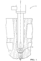
- Figure 1 sketches a high frequency resonator 10 placed in a cylinder head.
- the resonator extends along a longitudinal axis A and connects the spark plug 20 of the cylinder head.
- the high frequency resonator 10 comprises an external shield inside of which is placed a dielectric pre-form 40, itself containing a single layer coil 50, the gap between the coil 50 and the pre-form 40 being filled with a fluid 60.
- a cap 70 seals the assembly at the top.
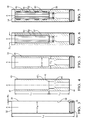
- a process to manufacture the resonator 10 is represented by the series of Figure 3 to 7 .
- the initial step of the method as per the invention consists in providing the individual components.
- the shield 30 ( Fig. 3 ) is a metallic tube open at both extremities, longitudinally extending from a top extremity 32 to a distant bottom extremity 34.
- the shield 30 is open at both extremities 32, 34, and is further provided at its bottom extremity 34 with an internal annular restriction forming a step 36 inwardly extending. From a material stand point, the shield 30 being a return path for the current has to be highly conductive at least on its inner surface 38. Copper is a preferred material to achieve this necessary high conductivity.
- Dimensionally the shield 30 should have a wall thickness 1 to 5 time the skin depth of the copper conductive portion. The skin depth is defined as the depth below the surface of the conductor at which the current density decays to 1/e of the current density at the surface.
- the shield 30 can be extruded or rolled or any other conventional process.
- copper is designated as a preferred material, alternative choices are possible provided the necessary conductivity property of the material.
- the pre-form 40 ( Fig. 4 ) is made of a dielectric material such as the commonly utilized for this type of application polytetrafluoroethylene [PTFE] or perfluoroalkoxy [PFA].
- the dielectric property is required to prevent shorts between the coil (50) and the shield (30) the electrical high frequency current travelling through the coil (50) while the shield (30) is a return path to the ground, as the coil (50) will be placed inside the pre-form (40).
- a dielectric loss factor tan ( ⁇ ) inferior to 10- 2 is preferred.
- the pre-form 40 is a tube open at both ends, longitudinally extending from a top end 42 to a bottom end 44.
- the pre-form 40 is open at both ends 42, 44, and radially limited by a wall 46.
- the pre-form 40 is a cylinder of revolution that is just slightly smaller than the shield 30 internal section.
- the pre-form 40 comprises two contiguous and coaxial hollow sections, a cylindrical upper section 46U and a lower section 46L which second diameter D2 is smaller than the first diameter D1 of the upper section 46U. Consequently, a radial step 48 inwardly extends at the intersection of the upper 46U and lower 46L sections.
- a pre-form 40 made of PTFE can be hot pressed, sintered and machined and, if made of PFA, it can be injection moulded to the final required shape. Alternatively, other materials having similar dielectric properties may be used and processed accordingly.
- the coil 50 ( Fig. 6 and Fig. 8 ) is a single layer coil with turns rolled around a non conductive core 52.
- a wire 53 commonly utilized for the purpose is of copper.
- the coil length is substantially equal to the length L1 of the upper section 46U and the coil diameter Dc is smaller than the first diameter D1 of said upper section 46U.
- the coil diameter Dc is understood to be the diameter measured over the wire 53 turns. It is then equal to the diameter of the core 52 augmented of two times the wire diameter. In a preferred embodiment two consecutive turns are not in contact with each other ( Fig. 8 ) thus leaving a minor void 59 between the turns of the wire 53.
- the minor void 59 is also continuous and helicoidally formed about the core 52.
- other material may be chosen for the wire 53 provided it has sufficient electrical conductivity properties.
- a coil wound with in-contact adjacent turns is possible.
- the coil 50 receives an upper terminal 54 and a lower terminal 56.
- the consecutive step consists in assembling the pre-form 40 inside the shield 30 ( Fig. 5 ).
- the pre-form 40 is inserted by presenting its bottom end 44 to the top extremity 32 of the shield 30 than, by axially engaging along the axis A, the pre-form 40 in the shield 30 until said bottom end 44 abuts against the internal step 36 formed at the bottom extremity 34 of the shield 30.
- the pre-form 40 is entirely inside the shield 30 and is ready to receive the coil 50.
- the pre-form 40 may have been made slightly larger that the internal section of the shield 30, thus the insertion requires to holding the shield 30 while the pre-form 40 is axially press-fitted into it. Once in place no additional feature is required to hold the pre-form 40 inside the shield 30.
- the pre-form 40 may be made smaller than the inner section of the shield 30, thus requiring fixing features (not represented) to maintain the pre-form 40 in place inside the shield 30.
- fixing features not represented
- pressing screws, crimping or an annular element that internally fits the pre-form 40 and externally fits the shield 30 could maintain the pre-form 40 in the shield 30.
- the shield (30) and the pre-form (40) are coaxial to the longitudinal axis A.
- the coil 50 is axially fully inserted into the upper section 46U of the pre-form 40 ( Fig. 6 ).
- a gap 57 remains between said components.
- the gap 57 comprises a main void 58 that is the annular volume comprised between the coil diameter Dc and the upper section diameter D1, as well as the minor void 59, both voids 58, 59, being in full fluid connection with each other.
- the lower part of the coil 50 When inside the upper section 46U and against the radial step 48, the lower part of the coil 50 slightly engages with a little press fit the lower section 46L of the pre-form, so the coil 50 is maintained coaxial to the pre-form 40 during the assembly process.
- this press-fit other feature holding the coil 50 coaxially to the pre-form 40 are possible.
- the next step of the process consists in filling the gap 57 with a fluid having physical properties enabling the resonator 10 to perform.
- a fluid having physical properties enabling the resonator 10 to perform.
- the viscosity of the fluid 60 has to be low enough to enable the fluid 60 to flow in every little area of the main void 58 and inside the minor void 59.
- the fluid 60 has to have low dielectric properties in order not to transmit electrical current under high frequency that would distort the coil 50 performance.
- a fluid having a dielectric loss factor inferior to 10 -2 is preferred.
- the elements of the resonator submitted to the underhood environment will thermally expand.
- the fluid 60 must be able to compensate for the differential thermal expansion of the core 52, the wire 53 and the pre-form 40. Provided this compensation, undesirable voids would create around the wire 53.
- Silicone gel or silicone oil ( Fig. 7 , Fig. 8 ) have the required properties and can be utilized for the purpose. Other choices are possible.
- Preventing the fluid 60 from accidentally exiting the pre-form 40 is important and an adequate sealing solution needs to be put in place depending on the fluid 60 chosen.
- silicone gel gets UV cured and/or heat cured at elevated temperature and it transforms into tacky gel. So, if used, the press-fit coil 50-to-pre-form 40 is sufficient to seal the assembly and, after curing the gel, no further protection is needed and the cured gel stays in the gap 57.
- silicone oil remains liquid so to prevent from dropping out a cover (not represented) or seal is required to be added.
- the cap 70 is placed at the top and seals the upper extremity 32 of the shield 30.
- the cap is made of electrically conductive material such as copper. Additionally to locking the assembly it provides electrical continuity for the shield 30.
- the cap 70 can be permanently fixed to the shield 30 thanks to welding, clamping or crimping or any other process providing sealing and electrical connection.
- a standard O-ring 80 is placed at the bottom of the resonator ( Fig. 2 ) and provides sealing between the dielectric insulation pre-form 40 and the ceramic shaft of the spark plug 20.
- the O-ring 80 aims at overcoming gaps from dimensional differences of the ceramic shaft at avoiding electrical surface discharges along the ceramic shaft to ground.
- An annular groove into the pre-form 40 helps to positioning and retaining the O-ring 80.
- the necessary quantity of fluid 60 may be poured in the pre-form 40 prior to engaging the coil 50 inside said pre-form 40.
- An adequate sealing device placed by the radial step 48 is to be provided.
Landscapes
- Engineering & Computer Science (AREA)
- Manufacturing & Machinery (AREA)
- Ignition Installations For Internal Combustion Engines (AREA)
Abstract
The invention discloses a method to manufacture a high frequency electrical resonator for the ignition system of an internal combustion engine, the method comprising the steps of:
providing a coil (50) and a tubular electrically conductive shield (30),
manufacturing a tubular encapsulation pre-form (40) having outer and inner dimensions such that the coil (50) freely enters the pre-form (40) which can itself fit inside the shield (30),
inserting the pre-form (40) inside the shield (30),
placing the coil (50) inside the pre-form (40) and,
filling the gap between the coil (50) and the pre-form (40) with a dielectric fluid (60) having a viscosity enabling to entirely fill the gap.
providing a coil (50) and a tubular electrically conductive shield (30),
manufacturing a tubular encapsulation pre-form (40) having outer and inner dimensions such that the coil (50) freely enters the pre-form (40) which can itself fit inside the shield (30),
inserting the pre-form (40) inside the shield (30),
placing the coil (50) inside the pre-form (40) and,
filling the gap between the coil (50) and the pre-form (40) with a dielectric fluid (60) having a viscosity enabling to entirely fill the gap.
Description
- The present invention relates to a method for manufacturing a high frequency ignition resonator and to the resonator made with the method disclosed.
- Ignition coils providing controlled ignition for automotive gasoline engines are built using a typical transformer like concepts. This implies to have a dense packaged primary and secondary winding which are tightly encapsulated. An alternative method to deliverer ignition energy to the combustion process is to use resonance structures. In this case, a single inductor and capacitor is tuned such that under resonance condition very high voltages are delivered. Such resonance structures are described too by capacitive loaded quarter-wave transmission lines. In both cases a very simple coil is needed.
- These resonances have extremely well defined geometric structures. The ignition current is typically conducted though the coil and the current return path is well defined by a conductive outer coaxial return.
- Between the simple coil and the coaxial return path very high voltages are built-up such that a suitable encapsulation is needed to provide high dielectric strength superior to 40 kV.mm-1, low parasitic capacitance tending to favor design with thick layer, and low dielectric loss - tan (δ) - inferior to 10-4. The dielectric loss factor - tan (δ) where δ is the lag angle between the current and voltage originated by dielectric losses - is a measure of the weak conductivity of a dielectric material. It provides an indicator of how much real power gets pushed through an insulator and can be calculated as the ratio of the real power applied to the dielectric over the reactive power that gets through the dielectric. The dielectric loss factor gives a good value to express the generated heat in relation to the stored energy of a specific dielectric material: lower tan (δ) less heat, less loss.
- Due to requirement of providing very high voltages, a particular attention of how to encapsulate these coils is needed.
- Conventional encapsulation methods are using vacuum potting method of the ignition coil using a material of very high dielectric strength. The insulation thicknesses between the winding layers are well experimentally proven and typically much less than 1mm.
- Unfortunately these materials have an intrinsic disadvantage of high dielectric losses at elevated frequencies (f> 1MHz). Materials with a high dielectric loss factor (tan(δ) > 10-2) are not suitable for the encapsulation of high frequency resonance structure. Such high dielectric loss will ultimately increase the primary electrical power requirement, furthermore physical size of such power generator hinder any automotive on-board operation.
- Alternative materials are any materials with low dielectric loss and usable at harsh under-hood temperature condition. Furthermore, such materials and a suitable process will have to provide encapsulated coils inside the before mentioned coaxial current return path with no electrical break down under the generated AC-voltages at all the environmental conditions.
- The materials of choice are all materials similar to polytetrafluoroethylene PTFE, or perfluoroalkoxy PFA and Silicon-Types. Unfortunately, these materials are difficult to process and expensive to purchase. Furthermore, this choice of material has a consequence on the material of the wire. Indeed the high processing temperatures, superior to 400 °C for PTFE or FPA, forbids the classical use of enameled copper winding to build the coil.
- Because of the differential voltages between the individual turns of the winding particular attention is needed for a most void free encapsulation.
- The thermal expansion of mentioned materials are high tending to generate voids and cracks within the encapsulation material by just leaving processing temperature (400 °C) and reaching operational temperature (about 100 °C). High stress is introduced which may lead to encapsulation cracks and dielectric failures. Even if these problems are solved, than normal thermal cycling still provokes stresses in the materials and therefore tends for cracks and or voids.
- Furthermore, the section between such subassembly coil spool and the encapsulation tend not to chemically bond using these materials and it can be demonstrated that at any case a certain amount of voids will remain. The solution to this behavior is to expand the pitch between the winding itself such that at any circumstance no corona alike behavior is blocking the resonance.
- There is a need for a method to encapsulate an enameled copper coil, still using the proposed materials while reducing the risk of non desired side effects such as voids and thermally provoked electric stress failures.
- Accordingly, it is an object of the present invention to provide a method which enables to manufacture an encapsulated ignition resonator free of the above mentioned problems.
- In carrying out the above object and other objects, features, and advantages, the present invention provides a method according to claim 1.
- In particular, the present invention discloses a method to manufacture a high frequency electrical resonator for the ignition system of an internal combustion engine. The method comprising the steps of providing a cylindrical core around which is wound a conductive wire for making a coil; providing a tubular electrically conductive shield; the method further comprises the steps of manufacturing a tubular encapsulation pre-form having outer and inner dimensions such that the coil freely enters the pre-form which can itself fit inside the shield. Once the components available the method consists in assembling said components in inserting the pre-form inside the shield; placing the coil inside the pre-form, thus creating an annular gap between the coil and the pre-form; providing a dielectric fluid and filling the gap with said dielectric fluid, the fluid having a viscosity enabling to entirely fill the gap. The fluid advantageously entirely fills the gap leaving the assembly free of voids. Furthermore, in operation the fluid permanently compensates the thermal expansion differences between the components. In particular the gap may comprise a main void between the diameter of the coil, measured over the wire turns, and the internal diameter of the pre-form, the main void being between 0.1 mm to 10 mm. Also, the wire may be wound so the turns are not contacting each other leaving a minor void between consecutive wire turns, the minor void being in fluid connection with the main void, the fluid filling the minor void. A preferred solution is to use a silicone based fluid which has the required dielectric properties and which is economically affordable. In particular the fluid may be an oil, a gel, a polyethelene (LDPE) or a polymethylpentene. More precisely, the fluid should have dielectric loss factor inferior to 10-2. The pre-form should also have a dielectric loss factor inferior to 10-2. To achieve this the material of the pre-form can be polytetrafluoroethylene (PTFE) or perfluoroalkoxy (PFA). The method further comprises the step of providing a cap, and installing said cap such that the pre-form, the coil and the fluid are advantageously retained inside the shield.
- The invention is also about a high frequency resonator for an internal combustion engine comprising a tubular shield surrounding a tubular dielectric pre-form in which is placed a single layer coil, the voids between the coil and the pre-form being filled by a dielectric fluid. The coil may have non contacting consecutive turns, the dielectric fluid filling the minor void between the turns of the wire, the dielectric fluid being silicone gel or silicone oil.
- The present invention is now described by way of example with reference to the accompanying drawings in which:
-
Figure 1 is a general view of a high frequency resonator in place in a cylinder head of an internal combustion engine. -
Figure 2 is a section of the resonator ofFigure 1 comprising an external shield, a pre-form and a coil. -
Figures 3 to 7 details in five consecutive steps the method as per the invention: -
Fig. 3 is a section of the external shield; -
Fig 4 is a section of the pre-form; -
Fig. 5 is the assembly of the pre-form into the shield. -
Fig. 6 is a section of the assembly ofFig. 3.3 where is further placed the coil inside the pre-form. -
Fig 7 is a section of the resonator after potting a fluid between the coil and the pre-form. -
Figure 8 is a magnified section of the assembly ofFigure 7 detailing wire turns of the coil. - In the following description for clarity purpose a bottom-top orientation is used as in
Figure 1 . The terms "bottom", "top" "over" "under" "above" "below" will ease the description without any intent to limit the scope of the invention. - In a motor vehicle,
Figure 1 sketches ahigh frequency resonator 10 placed in a cylinder head. The resonator extends along a longitudinal axis A and connects thespark plug 20 of the cylinder head. As perFigure 2 , thehigh frequency resonator 10 comprises an external shield inside of which is placed adielectric pre-form 40, itself containing asingle layer coil 50, the gap between thecoil 50 and the pre-form 40 being filled with a fluid 60. Acap 70 seals the assembly at the top. - A process to manufacture the
resonator 10 is represented by the series ofFigure 3 to 7 . - The initial step of the method as per the invention consists in providing the individual components.
- The shield 30 (
Fig. 3 ) is a metallic tube open at both extremities, longitudinally extending from atop extremity 32 to a distantbottom extremity 34. Theshield 30 is open at bothextremities bottom extremity 34 with an internal annular restriction forming astep 36 inwardly extending. From a material stand point, theshield 30 being a return path for the current has to be highly conductive at least on itsinner surface 38. Copper is a preferred material to achieve this necessary high conductivity. Dimensionally theshield 30 should have a wall thickness 1 to 5 time the skin depth of the copper conductive portion. The skin depth is defined as the depth below the surface of the conductor at which the current density decays to 1/e of the current density at the surface. It can be calculated as: d = (2p / ωµ)1/2.
where ρ = resistivity of conductor [Ωm].
ω = angular frequency of current = 2π x frequency.
µ= absolute magnetic permeability of conductor [Hm-1]. - From manufacturing stand point the
shield 30 can be extruded or rolled or any other conventional process. Although copper is designated as a preferred material, alternative choices are possible provided the necessary conductivity property of the material. - The pre-form 40 (
Fig. 4 ) is made of a dielectric material such as the commonly utilized for this type of application polytetrafluoroethylene [PTFE] or perfluoroalkoxy [PFA]. The dielectric property is required to prevent shorts between the coil (50) and the shield (30) the electrical high frequency current travelling through the coil (50) while the shield (30) is a return path to the ground, as the coil (50) will be placed inside the pre-form (40). A dielectric loss factor tan (δ) inferior to 10-2 is preferred. The pre-form 40 is a tube open at both ends, longitudinally extending from atop end 42 to abottom end 44. The pre-form 40 is open at both ends 42, 44, and radially limited by awall 46. Externally, the pre-form 40 is a cylinder of revolution that is just slightly smaller than theshield 30 internal section. Internally, the pre-form 40 comprises two contiguous and coaxial hollow sections, a cylindrical upper section 46U and a lower section 46L which second diameter D2 is smaller than the first diameter D1 of the upper section 46U. Consequently, aradial step 48 inwardly extends at the intersection of the upper 46U and lower 46L sections. From a manufacturing stand point, a pre-form 40 made of PTFE can be hot pressed, sintered and machined and, if made of PFA, it can be injection moulded to the final required shape. Alternatively, other materials having similar dielectric properties may be used and processed accordingly. - The coil 50 (
Fig. 6 andFig. 8 ) is a single layer coil with turns rolled around a nonconductive core 52. Awire 53 commonly utilized for the purpose is of copper. The coil length is substantially equal to the length L1 of the upper section 46U and the coil diameter Dc is smaller than the first diameter D1 of said upper section 46U. The coil diameter Dc is understood to be the diameter measured over thewire 53 turns. It is then equal to the diameter of the core 52 augmented of two times the wire diameter. In a preferred embodiment two consecutive turns are not in contact with each other (Fig. 8 ) thus leaving aminor void 59 between the turns of thewire 53. As thewire 53 is continuous and helicoidally wound around thecore 52, theminor void 59 is also continuous and helicoidally formed about thecore 52. Alternatively to copper, other material may be chosen for thewire 53 provided it has sufficient electrical conductivity properties. Also, a coil wound with in-contact adjacent turns is possible. - For electrical connection purposes, the
coil 50 receives anupper terminal 54 and alower terminal 56. - Once provided the
shield 30 and the pre-form 40, the consecutive step consists in assembling the pre-form 40 inside the shield 30 (Fig. 5 ). The pre-form 40 is inserted by presenting itsbottom end 44 to thetop extremity 32 of theshield 30 than, by axially engaging along the axis A, the pre-form 40 in theshield 30 until saidbottom end 44 abuts against theinternal step 36 formed at thebottom extremity 34 of theshield 30. When in abutment, the pre-form 40 is entirely inside theshield 30 and is ready to receive thecoil 50. - It is to be noted that the pre-form 40 may have been made slightly larger that the internal section of the
shield 30, thus the insertion requires to holding theshield 30 while the pre-form 40 is axially press-fitted into it. Once in place no additional feature is required to hold the pre-form 40 inside theshield 30. - Alternatively, the pre-form 40 may be made smaller than the inner section of the
shield 30, thus requiring fixing features (not represented) to maintain the pre-form 40 in place inside theshield 30. As non limiting examples pressing screws, crimping or an annular element that internally fits the pre-form 40 and externally fits theshield 30 could maintain the pre-form 40 in theshield 30. In place, the shield (30) and the pre-form (40) are coaxial to the longitudinal axis A. - Afterward, the
coil 50 is axially fully inserted into the upper section 46U of the pre-form 40 (Fig. 6 ). As the coil diameter Dc is smaller than the diameter D1 of the upper section 46U, agap 57 remains between said components. Thegap 57 comprises amain void 58 that is the annular volume comprised between the coil diameter Dc and the upper section diameter D1, as well as theminor void 59, bothvoids - When inside the upper section 46U and against the
radial step 48, the lower part of thecoil 50 slightly engages with a little press fit the lower section 46L of the pre-form, so thecoil 50 is maintained coaxial to the pre-form 40 during the assembly process. Alternatively to this press-fit, other feature holding thecoil 50 coaxially to the pre-form 40 are possible. - The next step of the process consists in filling the
gap 57 with a fluid having physical properties enabling theresonator 10 to perform. In particular the viscosity of the fluid 60 has to be low enough to enable the fluid 60 to flow in every little area of themain void 58 and inside theminor void 59. Also, the fluid 60 has to have low dielectric properties in order not to transmit electrical current under high frequency that would distort thecoil 50 performance. A fluid having a dielectric loss factor inferior to 10-2 is preferred. Furthermore, when in operation the elements of the resonator submitted to the underhood environment will thermally expand. The fluid 60 must be able to compensate for the differential thermal expansion of the core 52, thewire 53 and the pre-form 40. Provided this compensation, undesirable voids would create around thewire 53. Silicone gel or silicone oil (Fig. 7 ,Fig. 8 ) have the required properties and can be utilized for the purpose. Other choices are possible. - Preventing the fluid 60 from accidentally exiting the pre-form 40 is important and an adequate sealing solution needs to be put in place depending on the fluid 60 chosen. For instance, silicone gel gets UV cured and/or heat cured at elevated temperature and it transforms into tacky gel. So, if used, the press-fit coil 50-to-
pre-form 40 is sufficient to seal the assembly and, after curing the gel, no further protection is needed and the cured gel stays in thegap 57. - Alternatively to the gel, silicone oil remains liquid so to prevent from dropping out a cover (not represented) or seal is required to be added.
- The
cap 70 is placed at the top and seals theupper extremity 32 of theshield 30. The cap is made of electrically conductive material such as copper. Additionally to locking the assembly it provides electrical continuity for theshield 30. Thecap 70 can be permanently fixed to theshield 30 thanks to welding, clamping or crimping or any other process providing sealing and electrical connection. - A standard O-
ring 80 is placed at the bottom of the resonator (Fig. 2 ) and provides sealing between thedielectric insulation pre-form 40 and the ceramic shaft of thespark plug 20. The O-ring 80 aims at overcoming gaps from dimensional differences of the ceramic shaft at avoiding electrical surface discharges along the ceramic shaft to ground. An annular groove into the pre-form 40 helps to positioning and retaining the O-ring 80. - Alternatively to the above described sequence steps for the assembly, the necessary quantity of
fluid 60 may be poured in the pre-form 40 prior to engaging thecoil 50 inside saidpre-form 40. An adequate sealing device placed by theradial step 48 is to be provided.
Claims (15)
- Method to manufacture a high frequency electrical resonator (10) for the ignition system of an internal combustion engine, the method comprising the steps of:providing a cylindrical core (52) around which is wound a conductive wire (53) for making a coil (50),providing a tubular electrically conductive shield (30),the method being characterized in that is further comprises the steps ofmanufacturing a tubular encapsulation pre-form (40) having outer and inner dimensions such that the coil (50) freely enters the pre-form (40) which can itself fit inside the shield (30),inserting the pre-form (40) inside the shield (30),placing the coil (50) inside the pre-form (40), thus creating an annular gap (57) between the coil (50) and the pre-form (40),providing a dielectric fluid (60) and,filling the gap (57) with said dielectric fluid (60), the fluid (60) having a viscosity enabling to entirely fill the gap (57).
- A method as set in claim 1 wherein the gap (57) comprises a main void (58) that is between the diameter of the coil (Dc), measured over the wire turns, and the internal diameter (D1) of the pre-form (40), the main void (58) being between 0.1 mm to 10 mm.
- The method as set in any of the preceding claim wherein the wire (53) is wound so the turns are not contacting each other leaving a minor void (59) between consecutive wire turns, the minor void (59) being in fluid connection with the main void (58), the fluid (60) filling the minor void (59).
- A method as set in any of the preceding claim wherein the fluid (60) is silicone based.
- A method as set in any of the preceding claim wherein the fluid (60) is oil or a gel.
- A method as set in any of the claim 1 to 3 wherein the fluid (60) is polyethelene (LDPE).
- A method as set in any of the claim 1 to 3 wherein the fluid (60) is polymethylpentene.
- The method as set in any of the preceding claim wherein the fluid (60) has dielectric loss factor inferior to 10-2.
- A method a set in any of the preceding claim wherein the pre-form (40) has a dielectric loss factor inferior to 10-2.
- A method as set in any of the preceding claim wherein the material of the pre-form (40) is made of polytetrafluoroethylene (PTFE).
- A method as set in any of the claim 1 to 9 wherein the material of the pre-form (40) is made of perfluoroalkoxy (PFA).
- A method as set in any of the preceding claim further comprising the step of:providing a cap (70), and installing said cap (70) over the shield (30) such that the pre-form (40), the coil (50) and the fluid (60) are retained inside the shield (30).
- A high frequency resonator (10) for an internal combustion engine comprising a tubular shield (30) surrounding a tubular dielectric pre-form (40) in which is placed a single layer coil (50), the voids (58, 59) between the coil (50) and the pre-form (40) being filled by a dielectric fluid (60).
- A resonator as set in claim 13 wherein the coil (50) has non contacting consecutive turns, the dielectric fluid (60) filling the minor void (59) between the turns of the wire (53).
- A resonator as set in any of the claim 13 or 14 wherein the dielectric fluid (60) is silicone gel or silicone oil.
Priority Applications (1)
| Application Number | Priority Date | Filing Date | Title |
|---|---|---|---|
| EP10192210A EP2456027A1 (en) | 2010-11-23 | 2010-11-23 | Encapsulation of a high frequency resonator for the ignition system of an internal combustion engine |
Applications Claiming Priority (1)
| Application Number | Priority Date | Filing Date | Title |
|---|---|---|---|
| EP10192210A EP2456027A1 (en) | 2010-11-23 | 2010-11-23 | Encapsulation of a high frequency resonator for the ignition system of an internal combustion engine |
Publications (1)
| Publication Number | Publication Date |
|---|---|
| EP2456027A1 true EP2456027A1 (en) | 2012-05-23 |
Family
ID=44065438
Family Applications (1)
| Application Number | Title | Priority Date | Filing Date |
|---|---|---|---|
| EP10192210A Withdrawn EP2456027A1 (en) | 2010-11-23 | 2010-11-23 | Encapsulation of a high frequency resonator for the ignition system of an internal combustion engine |
Country Status (1)
| Country | Link |
|---|---|
| EP (1) | EP2456027A1 (en) |
Cited By (1)
| Publication number | Priority date | Publication date | Assignee | Title |
|---|---|---|---|---|
| CN103726972A (en) * | 2012-10-12 | 2014-04-16 | 博格华纳贝鲁系统股份有限公司 | Corona igniter with gas-tight hf plug connector |
Citations (2)
| Publication number | Priority date | Publication date | Assignee | Title |
|---|---|---|---|---|
| EP1662626A1 (en) * | 2004-11-29 | 2006-05-31 | Renault | New mounting method of a spark plug and bobbin assembly using a transmission of the tightning couple through the bobbin housing |
| WO2010043544A1 (en) * | 2008-10-13 | 2010-04-22 | Delphi Technologies, Inc. | Sparkplug with integrated coil |
-
2010
- 2010-11-23 EP EP10192210A patent/EP2456027A1/en not_active Withdrawn
Patent Citations (2)
| Publication number | Priority date | Publication date | Assignee | Title |
|---|---|---|---|---|
| EP1662626A1 (en) * | 2004-11-29 | 2006-05-31 | Renault | New mounting method of a spark plug and bobbin assembly using a transmission of the tightning couple through the bobbin housing |
| WO2010043544A1 (en) * | 2008-10-13 | 2010-04-22 | Delphi Technologies, Inc. | Sparkplug with integrated coil |
Cited By (4)
| Publication number | Priority date | Publication date | Assignee | Title |
|---|---|---|---|---|
| CN103726972A (en) * | 2012-10-12 | 2014-04-16 | 博格华纳贝鲁系统股份有限公司 | Corona igniter with gas-tight hf plug connector |
| WO2014056826A1 (en) * | 2012-10-12 | 2014-04-17 | Borgwarner Beru Systems Gmbh | Corona igniter with gas-tight hf plug connector |
| CN103726972B (en) * | 2012-10-12 | 2017-06-30 | 博格华纳贝鲁系统股份有限公司 | Corona ignition device with airtight high frequency plug-in connector |
| US9698575B2 (en) | 2012-10-12 | 2017-07-04 | Borgwarner Ludwigsburg Gmbh | Corona ignition device with gas-tight HF plug connector |
Similar Documents
| Publication | Publication Date | Title |
|---|---|---|
| US7071804B2 (en) | Stick-type ignition coil having improved structure against crack or dielectric discharge | |
| US9097232B2 (en) | Ignition coil assembly | |
| KR101835624B1 (en) | Corona igniter including ignition coil with improved isolation | |
| CA1078939A (en) | Electrical connector with adaptor for paper-insulated lead jacketed electrical cables and method | |
| US6216679B1 (en) | Ignition coil for an internal combustion engine | |
| US3394455A (en) | Method of constructing cast electrical bushings | |
| US8388359B1 (en) | Ignition terminal apparatus and method for forming a temperature-resistant insulating housing | |
| US7068135B1 (en) | Stick-type ignition coil having improved structure against crack or dielectric discharge | |
| CN114097052A (en) | Mutual inductor and method for isolating parts | |
| EP1351355B1 (en) | Ignition device for an internal combustion engine and a manufacturing method therefor | |
| US4174510A (en) | RF transformer | |
| EP1229619A2 (en) | Ignition coil with primary winding release | |
| EP3155625B1 (en) | Ignition coil | |
| US20030058077A1 (en) | Ignition coil and method of making | |
| JP5695900B2 (en) | Resonant circuit | |
| JP2005183995A (en) | Ignition coil for use in an Otto engine and method for manufacturing the ignition coil | |
| JPS62139308A (en) | Ignition coil for internal combustion engine | |
| CN103967683B (en) | Corona ignition device | |
| JPS588645B2 (en) | Kiki Kannoren Ketsubo Sen | |
| US20090066464A1 (en) | Ignition apparatus having bonded steel wire central core | |
| JPH04340311A (en) | Cable termination treatment method | |
| Doepken | UHV AC and DC gas-insulated bushings |
Legal Events
| Date | Code | Title | Description |
|---|---|---|---|
| PUAI | Public reference made under article 153(3) epc to a published international application that has entered the european phase |
Free format text: ORIGINAL CODE: 0009012 |
|
| AK | Designated contracting states |
Kind code of ref document: A1 Designated state(s): AL AT BE BG CH CY CZ DE DK EE ES FI FR GB GR HR HU IE IS IT LI LT LU LV MC MK MT NL NO PL PT RO RS SE SI SK SM TR |
|
| AX | Request for extension of the european patent |
Extension state: BA ME |
|
| 17P | Request for examination filed |
Effective date: 20121123 |
|
| 17Q | First examination report despatched |
Effective date: 20140414 |
|
| STAA | Information on the status of an ep patent application or granted ep patent |
Free format text: STATUS: THE APPLICATION IS DEEMED TO BE WITHDRAWN |
|
| 18D | Application deemed to be withdrawn |
Effective date: 20140826 |